JP2017535237A - 電動式過電流保護部を有するコンバイナボックス - Google Patents
電動式過電流保護部を有するコンバイナボックス Download PDFInfo
- Publication number
- JP2017535237A JP2017535237A JP2017520469A JP2017520469A JP2017535237A JP 2017535237 A JP2017535237 A JP 2017535237A JP 2017520469 A JP2017520469 A JP 2017520469A JP 2017520469 A JP2017520469 A JP 2017520469A JP 2017535237 A JP2017535237 A JP 2017535237A
- Authority
- JP
- Japan
- Prior art keywords
- combiner box
- inverter
- combiner
- rows
- switching
- Prior art date
- Legal status (The legal status is an assumption and is not a legal conclusion. Google has not performed a legal analysis and makes no representation as to the accuracy of the status listed.)
- Granted
Links
Images
Classifications
-
- H—ELECTRICITY
- H02—GENERATION; CONVERSION OR DISTRIBUTION OF ELECTRIC POWER
- H02H—EMERGENCY PROTECTIVE CIRCUIT ARRANGEMENTS
- H02H3/00—Emergency protective circuit arrangements for automatic disconnection directly responsive to an undesired change from normal electric working condition with or without subsequent reconnection ; integrated protection
- H02H3/08—Emergency protective circuit arrangements for automatic disconnection directly responsive to an undesired change from normal electric working condition with or without subsequent reconnection ; integrated protection responsive to excess current
-
- H—ELECTRICITY
- H02—GENERATION; CONVERSION OR DISTRIBUTION OF ELECTRIC POWER
- H02H—EMERGENCY PROTECTIVE CIRCUIT ARRANGEMENTS
- H02H7/00—Emergency protective circuit arrangements specially adapted for specific types of electric machines or apparatus or for sectionalised protection of cable or line systems, and effecting automatic switching in the event of an undesired change from normal working conditions
- H02H7/20—Emergency protective circuit arrangements specially adapted for specific types of electric machines or apparatus or for sectionalised protection of cable or line systems, and effecting automatic switching in the event of an undesired change from normal working conditions for electronic equipment
-
- H—ELECTRICITY
- H02—GENERATION; CONVERSION OR DISTRIBUTION OF ELECTRIC POWER
- H02S—GENERATION OF ELECTRIC POWER BY CONVERSION OF INFRARED RADIATION, VISIBLE LIGHT OR ULTRAVIOLET LIGHT, e.g. USING PHOTOVOLTAIC [PV] MODULES
- H02S40/00—Components or accessories in combination with PV modules, not provided for in groups H02S10/00 - H02S30/00
- H02S40/30—Electrical components
- H02S40/32—Electrical components comprising DC/AC inverter means associated with the PV module itself, e.g. AC modules
-
- H—ELECTRICITY
- H02—GENERATION; CONVERSION OR DISTRIBUTION OF ELECTRIC POWER
- H02S—GENERATION OF ELECTRIC POWER BY CONVERSION OF INFRARED RADIATION, VISIBLE LIGHT OR ULTRAVIOLET LIGHT, e.g. USING PHOTOVOLTAIC [PV] MODULES
- H02S40/00—Components or accessories in combination with PV modules, not provided for in groups H02S10/00 - H02S30/00
- H02S40/30—Electrical components
- H02S40/36—Electrical components characterised by special electrical interconnection means between two or more PV modules, e.g. electrical module-to-module connection
-
- H—ELECTRICITY
- H02—GENERATION; CONVERSION OR DISTRIBUTION OF ELECTRIC POWER
- H02S—GENERATION OF ELECTRIC POWER BY CONVERSION OF INFRARED RADIATION, VISIBLE LIGHT OR ULTRAVIOLET LIGHT, e.g. USING PHOTOVOLTAIC [PV] MODULES
- H02S50/00—Monitoring or testing of PV systems, e.g. load balancing or fault identification
- H02S50/10—Testing of PV devices, e.g. of PV modules or single PV cells
-
- Y—GENERAL TAGGING OF NEW TECHNOLOGICAL DEVELOPMENTS; GENERAL TAGGING OF CROSS-SECTIONAL TECHNOLOGIES SPANNING OVER SEVERAL SECTIONS OF THE IPC; TECHNICAL SUBJECTS COVERED BY FORMER USPC CROSS-REFERENCE ART COLLECTIONS [XRACs] AND DIGESTS
- Y02—TECHNOLOGIES OR APPLICATIONS FOR MITIGATION OR ADAPTATION AGAINST CLIMATE CHANGE
- Y02E—REDUCTION OF GREENHOUSE GAS [GHG] EMISSIONS, RELATED TO ENERGY GENERATION, TRANSMISSION OR DISTRIBUTION
- Y02E10/00—Energy generation through renewable energy sources
- Y02E10/50—Photovoltaic [PV] energy
Landscapes
- Engineering & Computer Science (AREA)
- Power Engineering (AREA)
- Inverter Devices (AREA)
- Supply And Distribution Of Alternating Current (AREA)
- Direct Current Feeding And Distribution (AREA)
- Photovoltaic Devices (AREA)
- Emergency Protection Circuit Devices (AREA)
- Protection Of Static Devices (AREA)
Abstract
Description
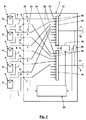
2 入力コネクタ
3 入力コネクタ
4 出力コネクタ
5 出力コネクタ
6 列線
7 列線
8 列
9 太陽電池モジュール
10 出力線
11 出力線
12 切替装置
13 切替接点
14 切替接点
15 切替接点
16 切替接点
17 接触子
18 接触子
19 モータ駆動部
20 過電流保護装置
21 電流センサ
22 接続線
23 インターフェース
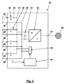
24 インバータ
25 入力コネクタ
26 入力コネクタ
27 バスバー
28 バスバー
29 接続線
30 電流センサ
31 入力リンク回路
32 DC/AC変換器
33 出力接続部
34 ACグリッド
35 過電流保護装置
36 インターフェース
Claims (15)
- −複数列(8)の太陽電池モジュール(9)からの列線(6、7)の入力コネクタ(2、3)と、
−インバータ(24)への一対の出力線(10、11)の出力コネクタ(4、5)と、
−前記列(8)を前記インバータ(24)へ接続するために使用され得る切替装置(12)であって、出力側切替接点(15、16)と、前記列(8)毎にまたは前記コンバイナボックス(1)内に恒久的に並列に接続される少なくとも前記列(8)の対毎に少なくとも1つの別個の入力側切替接点(13、14)とを含む切替装置(12)と、
−前記列(8)のそれぞれからまたはそれに発生する過電流、または少なくとも前記コンバイナボックス(1)内に恒久的に並列に接続された前記列(8)の前記対それぞれからまたはそれに発生する過電流を遮断する過電流保護装置(20)と、を含むコンバイナボックス(1)において、
−前記切替装置(12)は、前記列(8)を前記インバータ(24)から切り離すために作動され得る切替接点駆動部を有し、
−前記過電流保護装置(20)は、前記列(8)のそれぞれからまたはそれへ流れる電流、または少なくとも前記コンバイナボックス(1)内に恒久的に並列に接続された前記列(8)の前記対のそれぞれからまたはそれへ流れる電流を測定する電流センサ(21)を含み、前記過電流保護装置(20)はさらに、測定電流が過電流限界を越えると前記過電流限界を越える電流が流れ出るまたは流れ込む少なくとも前記列(8)または前記列(8)の前記対を前記インバータ(24)から切り離すために切替接点駆動部を作動させるように構成され、
前記切替接点駆動部は複数列(8)に関連付けられたまたは前記コンバイナボックス(1)内に恒久的に並列に接続された複数対の列(8)に関連付けられた複数切替接点(13〜16)の共通移動駆動部を有することを特徴とするコンバイナボックス(1)。 - 請求項1に記載のコンバイナボックス(1)において、前記複数列(8)の数、または前記コンバイナボックス(1)内に恒久的に並列に接続された前記複数対列(8)の数は少なくとも5、好適には少なくとも10である、ことを特徴とするコンバイナボックス(1)。
- 請求項1または2に記載のコンバイナボックス(1)において、前記共通移動駆動部は、前記複数列(8)に関連付けられたまたは前記コンバイナボックス(1)内に恒久的に並列に接続された前記複数対の列(8)に関連付けられた同極のすべての入力側切替接点(13、14)の出力側切替接点(15、16)を含む共通接触要素(17、18)を移動させる、ことを特徴とするコンバイナボックス(1)。
- 請求項3に記載のコンバイナボックス(1)において、前記共通移動駆動部は、前記列(8)、または前記コンバイナボックス(1)内に恒久的に並列に接続された前記対の列(8)のすべての同極個別入力側切替接点(13、14)の出力側切替接点(15、16)を有する共通接触要素(17、18)を移動させる、ことを特徴とするコンバイナボックス(1)。
- 請求項1乃至4の何れか一項に記載のコンバイナボックス(1)において、前記コンバイナボックス(1)内に配置されるとともに前記列線(6、7)と前記出力線(4、5)の中にまたはその間に接続される前記過電流保護装置(20)の一部は前記電流センサ(21)と前記切替接点(13〜16)で構成される、ことを特徴とするコンバイナボックス(1)。
- 請求項1乃至5の何れか一項に記載のコンバイナボックス(1)において、前記切替装置(12)は、前記列(8)のそれぞれのすべての極、または少なくとも前記コンバイナボックス(1)内に恒久的に並列に接続された列(8)の各対のすべての極を前記インバータ(24)から切り離す、ことを特徴とするコンバイナボックス(1)。
- 請求項1乃至6の何れか一項に記載のコンバイナボックス(1)において、前記電流センサ(21)は前記列(8)のそれぞれから流れる電流を測定する、ことを特徴とするコンバイナボックス(1)。
- 請求項1乃至7の何れか一項に記載のコンバイナボックス(1)において、前記切替装置(12)はノーマルオンタイプである、ことを特徴とするコンバイナボックス(1)。
- 請求項1乃至7の何れか一項に記載のコンバイナボックス(1)において、前記共通移動駆動部はばね駆動部を含む、ことを特徴とするコンバイナボックス(1)。
- 請求項1乃至9の何れか一項に記載のコンバイナボックス(1)において、前記共通移動駆動部は、前記関連列(8)を前記インバータ(24)へ接続するために作動され得るモータ駆動部(19)を含む、ことを特徴とするコンバイナボックス(1)。
- 請求項10に記載のコンバイナボックス(1)において、前記インバータ(24)からの接続信号の信号入力部が存在し、前記切替装置(12)は、前記接続信号を受信した後に前記列(8)を前記インバータ(24)へ接続するために各共通駆動部を作動させるように構成される、ことを特徴とするコンバイナボックス(1)。
- 請求項1乃至11の何れか一項に記載のコンバイナボックス(1)において、前記インバータ(24)からの切り離し信号の信号入力部が存在し、前記切替装置(12)は前記切り離し信号を受信した後に前記列(8)を前記インバータ(24)から切り離すために各共通移動駆動部を作動させるように構成される、ことを特徴とするコンバイナボックス(1)。
- 請求項11または12に記載のコンバイナボックス(1)において、前記信号入力部は、前記出力線(10、11)上に変調される有線の電力線通信信号または無線信号用のインターフェース(23)である、ことを特徴とするコンバイナボックス(1)。
- インバータ(24)を含む太陽電池装置において、
少なくとも1つのコンバイナボックス(1)を介し並列に接続された複数列(8)の太陽電池モジュール(9)と、
前記コンバイナボックス(1)のそれぞれから流れる電流を前記インバータ(24)内で測定するために使用される電流センサ(30)をさらに含み、
前記コンバイナボックス(1)のそれぞれは請求項13に記載のように構成されることと、第2の過電流限界を越える測定電流の場合、前記インバータ(24)は前記切り離し信号を、前記第2の過電流限界を越える電流が流れる出る前記コンバイナボックス(1)へ少なくとも出力することとを特徴とする太陽電池装置。 - 請求項14に記載の太陽電池装置において、前記コンバイナボックス(1)のそれぞれの前記過電流保護装置(20)を含むDC側全過電流安全装置の一部であって前記インバータ内に配置され各コンバイナボックスの前記出力線(10、11)内にまたはその間に接続される一部は前記電流センサ(30)で構成されることを特徴とする太陽電池装置。
Applications Claiming Priority (3)
| Application Number | Priority Date | Filing Date | Title |
|---|---|---|---|
| DE102014115601.3A DE102014115601B3 (de) | 2014-10-27 | 2014-10-27 | Combinerbox mit motorischer Überstromsicherung |
| DE102014115601.3 | 2014-10-27 | ||
| PCT/EP2015/073816 WO2016066429A1 (de) | 2014-10-27 | 2015-10-14 | Combinerbox mit motorischer überstromsicherung |
Publications (2)
| Publication Number | Publication Date |
|---|---|
| JP2017535237A true JP2017535237A (ja) | 2017-11-24 |
| JP6434138B2 JP6434138B2 (ja) | 2018-12-05 |
Family
ID=54324982
Family Applications (1)
| Application Number | Title | Priority Date | Filing Date |
|---|---|---|---|
| JP2017520469A Expired - Fee Related JP6434138B2 (ja) | 2014-10-27 | 2015-10-14 | 電動式過電流保護部を有するコンバイナボックス |
Country Status (6)
| Country | Link |
|---|---|
| US (1) | US10084303B2 (ja) |
| EP (1) | EP3213407B1 (ja) |
| JP (1) | JP6434138B2 (ja) |
| CN (1) | CN107078692B (ja) |
| DE (1) | DE102014115601B3 (ja) |
| WO (1) | WO2016066429A1 (ja) |
Cited By (2)
| Publication number | Priority date | Publication date | Assignee | Title |
|---|---|---|---|---|
| WO2022208809A1 (ja) * | 2021-03-31 | 2022-10-06 | 東芝三菱電機産業システム株式会社 | 電力変換システム |
| JP2024040384A (ja) * | 2020-04-13 | 2024-03-25 | 華為数字能源技術有限公司 | 光発電システムの保護装置及び保護方法並びに光発電システム |
Families Citing this family (9)
| Publication number | Priority date | Publication date | Assignee | Title |
|---|---|---|---|---|
| ITUA20163443A1 (it) * | 2016-04-26 | 2017-10-26 | Edoardo Sbaraglia | Sistema di monitoraggio dell'efficienza di ogni singolo modulo fotovoltaico facente parte di una stringa di moduli fotovoltaici in un impianto fotovoltaico. |
| EP3462607A1 (en) * | 2017-10-02 | 2019-04-03 | Nederlandse Organisatie voor toegepast- natuurwetenschappelijk onderzoek TNO | Insulation piercing cable connection system |
| JP7129008B2 (ja) | 2018-11-29 | 2022-09-01 | トヨタ自動車株式会社 | 電源システム |
| JP7025716B2 (ja) * | 2018-11-29 | 2022-02-25 | トヨタ自動車株式会社 | 電源システム |
| US11175318B2 (en) * | 2019-08-28 | 2021-11-16 | Novatek Microelectronics Corp. | Overcurrent detector for a multi-channel level shifter module |
| US11146210B2 (en) * | 2019-12-06 | 2021-10-12 | Sma Solar Technology Ag | Method of repowering a photovoltaic plant |
| CN116615851A (zh) | 2021-02-20 | 2023-08-18 | 华为数字能源技术有限公司 | 一种光伏系统、直流汇流箱及故障隔离方法 |
| KR102550720B1 (ko) * | 2023-03-07 | 2023-07-03 | 주식회사 더케이코리아 | 태양광 멀티스트링 12채널 접속함 |
| CN118041227B (zh) * | 2024-04-12 | 2024-06-21 | 浑源县源阳新能源发电有限公司 | 一种用于光伏发电汇流箱的温度过载保护装置 |
Citations (6)
| Publication number | Priority date | Publication date | Assignee | Title |
|---|---|---|---|---|
| JPS4963439U (ja) * | 1972-09-13 | 1974-06-04 | ||
| US20070107767A1 (en) * | 2005-11-16 | 2007-05-17 | Arizona Public Service Company | DC power-generation system and integral control apparatus therefor |
| JP2008527749A (ja) * | 2005-01-18 | 2008-07-24 | ソーラー セントリー コーポレーション | 光発電システムの監視システム及びその方法 |
| DE102008008505A1 (de) * | 2008-02-11 | 2009-08-13 | Siemens Aktiengesellschaft | PV-Teilgenerator-Anschlusskasten für eine PV-Anlage sowie PV-Anlage mit einer Vielzahl derartiger PV-Teilgenerator-Anschlusskästen |
| JP2013501497A (ja) * | 2009-08-06 | 2013-01-10 | エスエムエー ソーラー テクノロジー アーゲー | 複数のストリングの光起電モジュールから電力グリッドに電気エネルギーを供給するための装置 |
| WO2014015947A2 (de) * | 2012-07-26 | 2014-01-30 | Ellenberger & Poensgen Gmbh | Vorrichtung zum sicheren schalten einer photovoltaikanlage |
Family Cites Families (12)
| Publication number | Priority date | Publication date | Assignee | Title |
|---|---|---|---|---|
| US20060237058A1 (en) * | 2005-04-25 | 2006-10-26 | Mcclintock Ronald B | Direct current combiner box with power monitoring, ground fault detection and communications interface |
| EP1946418A2 (en) * | 2005-10-24 | 2008-07-23 | Conergy AG | Switch-fuse with control management for solar cells |
| CN201352713Y (zh) * | 2009-02-05 | 2009-11-25 | 合肥阳光电源有限公司 | 一种光伏阵列汇流箱 |
| US8217534B2 (en) * | 2009-05-20 | 2012-07-10 | General Electric Company | Power generator distributed inverter |
| WO2011057255A2 (en) * | 2009-11-09 | 2011-05-12 | Solarbos, Inc. | System for combining direct current power from multiple inputs |
| US8218274B2 (en) * | 2009-12-15 | 2012-07-10 | Eaton Corporation | Direct current arc fault circuit interrupter, direct current arc fault detector, noise blanking circuit for a direct current arc fault circuit interrupter, and method of detecting arc faults |
| US8837097B2 (en) * | 2010-06-07 | 2014-09-16 | Eaton Corporation | Protection, monitoring or indication apparatus for a direct current electrical generating apparatus or a plurality of strings |
| US20120024337A1 (en) * | 2010-07-29 | 2012-02-02 | John Bellacicco | Apparatus facilitating wiring of multiple solar panels |
| US8687348B2 (en) * | 2011-08-31 | 2014-04-01 | Bentek Corporation | Integrated safety disconnects for power systems |
| US9397235B2 (en) * | 2011-12-02 | 2016-07-19 | Schneider Elelctric Usa, Inc. | Photovoltaic string combiner with disconnect having provision for converting between grounded and ungrounded systems |
| US8587906B2 (en) * | 2012-04-05 | 2013-11-19 | Eaton Corporation | Photovotaic system including hybrid bi-directional DC contactors and method of detection and isolation of faults therein |
| US9589752B2 (en) * | 2013-05-03 | 2017-03-07 | Shoals Technologies Group, Llc | Disconnect cabinet with wireless monitoring capability |
-
2014
- 2014-10-27 DE DE102014115601.3A patent/DE102014115601B3/de not_active Expired - Fee Related
-
2015
- 2015-10-14 EP EP15780872.6A patent/EP3213407B1/de not_active Not-in-force
- 2015-10-14 JP JP2017520469A patent/JP6434138B2/ja not_active Expired - Fee Related
- 2015-10-14 WO PCT/EP2015/073816 patent/WO2016066429A1/de not_active Ceased
- 2015-10-14 CN CN201580058379.4A patent/CN107078692B/zh not_active Expired - Fee Related
-
2017
- 2017-04-26 US US15/497,673 patent/US10084303B2/en not_active Expired - Fee Related
Patent Citations (6)
| Publication number | Priority date | Publication date | Assignee | Title |
|---|---|---|---|---|
| JPS4963439U (ja) * | 1972-09-13 | 1974-06-04 | ||
| JP2008527749A (ja) * | 2005-01-18 | 2008-07-24 | ソーラー セントリー コーポレーション | 光発電システムの監視システム及びその方法 |
| US20070107767A1 (en) * | 2005-11-16 | 2007-05-17 | Arizona Public Service Company | DC power-generation system and integral control apparatus therefor |
| DE102008008505A1 (de) * | 2008-02-11 | 2009-08-13 | Siemens Aktiengesellschaft | PV-Teilgenerator-Anschlusskasten für eine PV-Anlage sowie PV-Anlage mit einer Vielzahl derartiger PV-Teilgenerator-Anschlusskästen |
| JP2013501497A (ja) * | 2009-08-06 | 2013-01-10 | エスエムエー ソーラー テクノロジー アーゲー | 複数のストリングの光起電モジュールから電力グリッドに電気エネルギーを供給するための装置 |
| WO2014015947A2 (de) * | 2012-07-26 | 2014-01-30 | Ellenberger & Poensgen Gmbh | Vorrichtung zum sicheren schalten einer photovoltaikanlage |
Cited By (3)
| Publication number | Priority date | Publication date | Assignee | Title |
|---|---|---|---|---|
| JP2024040384A (ja) * | 2020-04-13 | 2024-03-25 | 華為数字能源技術有限公司 | 光発電システムの保護装置及び保護方法並びに光発電システム |
| JP7648819B2 (ja) | 2020-04-13 | 2025-03-18 | 華為数字能源技術有限公司 | 光発電システムの保護装置及び保護方法並びに光発電システム |
| WO2022208809A1 (ja) * | 2021-03-31 | 2022-10-06 | 東芝三菱電機産業システム株式会社 | 電力変換システム |
Also Published As
| Publication number | Publication date |
|---|---|
| EP3213407A1 (de) | 2017-09-06 |
| CN107078692A (zh) | 2017-08-18 |
| CN107078692B (zh) | 2019-04-05 |
| WO2016066429A1 (de) | 2016-05-06 |
| US20170229856A1 (en) | 2017-08-10 |
| US10084303B2 (en) | 2018-09-25 |
| JP6434138B2 (ja) | 2018-12-05 |
| EP3213407B1 (de) | 2018-03-21 |
| DE102014115601B3 (de) | 2016-01-07 |
Similar Documents
| Publication | Publication Date | Title |
|---|---|---|
| JP6434138B2 (ja) | 電動式過電流保護部を有するコンバイナボックス | |
| US11677232B2 (en) | Quick battery disconnect system for high current circuits | |
| CN105493397B (zh) | 用于断路器放电的光伏逆变器的电路布置和该电路布置的应用 | |
| AU2009268165B2 (en) | High-speed circuit breaker for a high-performance battery in an isolated direct current network | |
| US8570713B2 (en) | Electrical distribution system including micro electro-mechanical switch (MEMS) devices | |
| JP6101283B2 (ja) | スイッチング部材の接点ギャップにわたって発生するアークを抑圧するための回路装置 | |
| CA2705918C (en) | Short-circuit limiting apparatus in a low-voltage installation | |
| CN113039718B (zh) | 具有保护功能的光伏串汇流箱 | |
| CN113875111B (zh) | 一种分断装置及逆变器系统 | |
| JP6581799B2 (ja) | 保護システム、及び保護方法 | |
| CN110892600A (zh) | 充电系统 | |
| CN104781898A (zh) | 用于控制连接在下游的电机的能量供给的开关设备 | |
| AU2015316569B2 (en) | Current management device | |
| EP3050117B1 (en) | Combiner box of a dc part of a pv plant | |
| JP6391993B2 (ja) | 直流遮断装置 | |
| CN102844955B (zh) | 分离电能量源与负载的关断设备和具有关断设备的电路系统 | |
| RU2335059C1 (ru) | Способ контроля отказа срабатывания пункта автоматического включения резерва в кольцевой сети, питающейся от разных шин двухтрансформаторной подстанции | |
| KR20100009047A (ko) | 컴팩트 배전반 용 접지개폐기 및 이를 갖는 캠팩트 배전반 | |
| CN205992731U (zh) | 一种具有选择性跳闸功能的弧光保护系统 | |
| RU113869U1 (ru) | Устройство поперечной емкостной компенсации в тяговой сети переменного тока | |
| SU919005A1 (ru) | Высоковольтное распределительное устройство | |
| JP6331612B2 (ja) | 配電系統保護装置及び変電設備 | |
| GB2574038A (en) | Two-stage switching mechanism for use in a DC circuit | |
| PL224590B1 (pl) | Wyłącznik hybrydowy prądu stałego |
Legal Events
| Date | Code | Title | Description |
|---|---|---|---|
| A621 | Written request for application examination |
Free format text: JAPANESE INTERMEDIATE CODE: A621 Effective date: 20181012 |
|
| A871 | Explanation of circumstances concerning accelerated examination |
Free format text: JAPANESE INTERMEDIATE CODE: A871 Effective date: 20181012 |
|
| A975 | Report on accelerated examination |
Free format text: JAPANESE INTERMEDIATE CODE: A971005 Effective date: 20181019 |
|
| TRDD | Decision of grant or rejection written | ||
| A01 | Written decision to grant a patent or to grant a registration (utility model) |
Free format text: JAPANESE INTERMEDIATE CODE: A01 Effective date: 20181030 |
|
| A61 | First payment of annual fees (during grant procedure) |
Free format text: JAPANESE INTERMEDIATE CODE: A61 Effective date: 20181107 |
|
| R150 | Certificate of patent or registration of utility model |
Ref document number: 6434138 Country of ref document: JP Free format text: JAPANESE INTERMEDIATE CODE: R150 |
|
| R250 | Receipt of annual fees |
Free format text: JAPANESE INTERMEDIATE CODE: R250 |
|
| LAPS | Cancellation because of no payment of annual fees |