JP2017536663A - Lighting component with switchable diffuser - Google Patents
Lighting component with switchable diffuser Download PDFInfo
- Publication number
- JP2017536663A JP2017536663A JP2017524022A JP2017524022A JP2017536663A JP 2017536663 A JP2017536663 A JP 2017536663A JP 2017524022 A JP2017524022 A JP 2017524022A JP 2017524022 A JP2017524022 A JP 2017524022A JP 2017536663 A JP2017536663 A JP 2017536663A
- Authority
- JP
- Japan
- Prior art keywords
- reflective
- switchable diffuser
- major surface
- state
- optical
- Prior art date
- Legal status (The legal status is an assumption and is not a legal conclusion. Google has not performed a legal analysis and makes no representation as to the accuracy of the status listed.)
- Pending
Links
Images

















Classifications
-
- F—MECHANICAL ENGINEERING; LIGHTING; HEATING; WEAPONS; BLASTING
- F21—LIGHTING
- F21V—FUNCTIONAL FEATURES OR DETAILS OF LIGHTING DEVICES OR SYSTEMS THEREOF; STRUCTURAL COMBINATIONS OF LIGHTING DEVICES WITH OTHER ARTICLES, NOT OTHERWISE PROVIDED FOR
- F21V14/00—Controlling the distribution of the light emitted by adjustment of elements
- F21V14/003—Controlling the distribution of the light emitted by adjustment of elements by interposition of elements with electrically controlled variable light transmissivity, e.g. liquid crystal elements or electrochromic devices
-
- F—MECHANICAL ENGINEERING; LIGHTING; HEATING; WEAPONS; BLASTING
- F21—LIGHTING
- F21K—NON-ELECTRIC LIGHT SOURCES USING LUMINESCENCE; LIGHT SOURCES USING ELECTROCHEMILUMINESCENCE; LIGHT SOURCES USING CHARGES OF COMBUSTIBLE MATERIAL; LIGHT SOURCES USING SEMICONDUCTOR DEVICES AS LIGHT-GENERATING ELEMENTS; LIGHT SOURCES NOT OTHERWISE PROVIDED FOR
- F21K9/00—Light sources using semiconductor devices as light-generating elements, e.g. using light-emitting diodes [LED] or lasers
- F21K9/60—Optical arrangements integrated in the light source, e.g. for improving the colour rendering index or the light extraction
- F21K9/69—Details of refractors forming part of the light source
-
- F—MECHANICAL ENGINEERING; LIGHTING; HEATING; WEAPONS; BLASTING
- F21—LIGHTING
- F21V—FUNCTIONAL FEATURES OR DETAILS OF LIGHTING DEVICES OR SYSTEMS THEREOF; STRUCTURAL COMBINATIONS OF LIGHTING DEVICES WITH OTHER ARTICLES, NOT OTHERWISE PROVIDED FOR
- F21V3/00—Globes; Bowls; Cover glasses
-
- F—MECHANICAL ENGINEERING; LIGHTING; HEATING; WEAPONS; BLASTING
- F21—LIGHTING
- F21V—FUNCTIONAL FEATURES OR DETAILS OF LIGHTING DEVICES OR SYSTEMS THEREOF; STRUCTURAL COMBINATIONS OF LIGHTING DEVICES WITH OTHER ARTICLES, NOT OTHERWISE PROVIDED FOR
- F21V7/00—Reflectors for light sources
- F21V7/22—Reflectors for light sources characterised by materials, surface treatments or coatings, e.g. dichroic reflectors
-
- F—MECHANICAL ENGINEERING; LIGHTING; HEATING; WEAPONS; BLASTING
- F21—LIGHTING
- F21Y—INDEXING SCHEME ASSOCIATED WITH SUBCLASSES F21K, F21L, F21S and F21V, RELATING TO THE FORM OR THE KIND OF THE LIGHT SOURCES OR OF THE COLOUR OF THE LIGHT EMITTED
- F21Y2115/00—Light-generating elements of semiconductor light sources
- F21Y2115/10—Light-emitting diodes [LED]
Landscapes
- Engineering & Computer Science (AREA)
- General Engineering & Computer Science (AREA)
- Chemical & Material Sciences (AREA)
- Crystallography & Structural Chemistry (AREA)
- Microelectronics & Electronic Packaging (AREA)
- Optics & Photonics (AREA)
- Physics & Mathematics (AREA)
- Optical Elements Other Than Lenses (AREA)
- Circuit Arrangement For Electric Light Sources In General (AREA)
- Liquid Crystal (AREA)
- Radiation-Therapy Devices (AREA)
- Arrangement Of Elements, Cooling, Sealing, Or The Like Of Lighting Devices (AREA)
- Planar Illumination Modules (AREA)
Abstract
光学容積と、その中に少なくとも部分的に配設された切り替え可能な拡散体と、を含む照明構成要素が説明される。この光学容積は、光注入領域と、少なくとも1つの反射性又は半透過性の外側主面と、出力主面と、を備えている。この少なくとも1つの反射性又は半透過性の外側主面は、光学容積の対向する境界を画定する。出力主面は、少なくとも1つの反射性又は半透過性の外側主面の1つ以上の遠位端部に隣接している。この切り替え可能な拡散体は、少なくとも第1の状態と第2の状態とを有する。切り替え可能な拡散体は、光学容積の光軸に平行ではない面法線を有することができる。少なくとも1つの反射性又は半透過性の外側主面は、空間的に変化する反射特性を有してもよい。Illumination components are described that include an optical volume and a switchable diffuser disposed at least partially therein. The optical volume includes a light injection region, at least one reflective or semi-transmissive outer main surface, and an output main surface. The at least one reflective or translucent outer major surface defines opposing boundaries of the optical volume. The output major surface is adjacent to one or more distal ends of at least one reflective or semi-transmissive outer major surface. The switchable diffuser has at least a first state and a second state. The switchable diffuser can have a surface normal that is not parallel to the optical axis of the optical volume. At least one reflective or translucent outer major surface may have spatially varying reflective properties.
Description
照明構成要素は、その光出力を方向付けるための反射体を含むことができる。また、光出力の一様性を向上させるために、拡散体を含めることもできる。いくつかの場合には、照明構成要素からの光出力を電気的に調整できることが望ましい場合がある。 The illumination component can include a reflector for directing its light output. A diffuser can also be included to improve the uniformity of the light output. In some cases, it may be desirable to be able to electrically adjust the light output from the lighting components.
本明細書のいくつかの態様では、光学容積(optical volume)と、その中に少なくとも部分的に配設された切り替え可能な拡散体とを含む照明構成要素が提示される。この光学容積は、光注入領域、少なくとも1つの反射性又は半透過性の外側主面、及び出力主面を備えている。出力主面は、少なくとも1つの反射性又は半透過性の外側主面の1つ以上の遠位端部に隣接している。切り替え可能な拡散体は、少なくとも第1の状態と第2の状態とを有し、第1の状態は第1のヘイズによって特徴付けられ、第2の状態は第1のヘイズとは異なる第2のヘイズによって特徴付けられる。第1の切り替え可能な拡散体の少なくとも一部は、光学容積の光軸に平行でない面法線を有する。当該少なくとも1つの反射性又は半透過性の外側主面は、光学容積の対向する境界を画定する。 In some aspects herein, an illumination component is presented that includes an optical volume and a switchable diffuser disposed at least partially therein. The optical volume includes a light injection region, at least one reflective or translucent outer major surface, and an output major surface. The output major surface is adjacent to one or more distal ends of at least one reflective or semi-transmissive outer major surface. The switchable diffuser has at least a first state and a second state, wherein the first state is characterized by a first haze and the second state is a second different from the first haze. Characterized by haze. At least a portion of the first switchable diffuser has a surface normal that is not parallel to the optical axis of the optical volume. The at least one reflective or translucent outer major surface defines opposing boundaries of the optical volume.
本明細書のいくつかの態様では、光学容積と、その中に少なくとも部分的に配設された切り替え可能な拡散体とを含む照明構成要素が提示される。光学容積は、少なくとも1つの反射性又は半透過性の外側主面と、これに隣接する光注入領域と、光注入領域の反対側の遠位面と、を備えている。切り替え可能な拡散体は、少なくとも第1の状態と第2の状態とを有し、第1の状態は第1のヘイズによって特徴付けられ、第2の状態は第1のヘイズとは異なる第2のヘイズによって特徴付けられる。少なくとも1つの反射性又は半透過性の外側主面は、空間的に変化する反射の特性を有し、この少なくとも1つの反射性又は半透過性の外側主面は、光学容積の対向する境界を画定する。 In some aspects herein, an illumination component is presented that includes an optical volume and a switchable diffuser disposed at least partially therein. The optical volume includes at least one reflective or translucent outer major surface, a light injection region adjacent thereto, and a distal surface opposite the light injection region. The switchable diffuser has at least a first state and a second state, wherein the first state is characterized by a first haze and the second state is a second different from the first haze. Characterized by haze. At least one reflective or semi-transmissive outer major surface has a spatially varying reflection characteristic, and the at least one reflective or semi-transmissive outer major surface defines an opposing boundary of the optical volume. Define.
本明細書のいくつかの態様では、光学容積と、その中に少なくとも部分的に配設された切り替え可能な拡散体とを含む照明構成要素が提示される。光学容積は、少なくとも1つの反射性又は半透過性の外側主面と、これに隣接する光注入領域と、光注入領域の反対側の遠位面と、を備えている。切り替え可能な拡散体は、少なくとも第1の状態と第2の状態とを有し、第1の状態は第1のヘイズによって特徴付けられ、第2の状態は第1のヘイズとは異なる第2のヘイズによって特徴付けられる。少なくとも1つの反射性又は半透過性の外側主面は、光注入領域から出力主面まで延在する1つ以上の面を含み、光注入領域の反対側の出力主面に近接して配設された追加の面を含む。 In some aspects herein, an illumination component is presented that includes an optical volume and a switchable diffuser disposed at least partially therein. The optical volume includes at least one reflective or translucent outer major surface, a light injection region adjacent thereto, and a distal surface opposite the light injection region. The switchable diffuser has at least a first state and a second state, wherein the first state is characterized by a first haze and the second state is a second different from the first haze. Characterized by haze. The at least one reflective or translucent outer major surface includes one or more surfaces extending from the light injection region to the output major surface and is disposed proximate to the output major surface opposite the light injection region. Include additional faces.
本明細書のいくつかの態様では、少なくとも1つの傾斜主面を有する一体型で光学的に透明な構成要素と、少なくとも1つの傾斜主面の少なくとも一部に取り付けられ、それを覆う少なくとも1つの拡散体と、を含む照明構成要素が提示される。一体型で光学的に透明な構成要素は、少なくとも1つの傾斜主面に隣接する入力面と、少なくとも1つの傾斜主面に隣接し、かつ入力面の反対側の出力面と、を含む。少なくとも1つの拡散体は、少なくとも第1の状態と、第1の状態とは異なる第2の状態と、を有する第1の切り替え可能な拡散体を備える。少なくとも1つの傾斜主面は、入力面から出力面まで実質的に収束するか又は広がるが、その両方ではない。 In some aspects of the specification, an integral optically transparent component having at least one inclined major surface and at least one attached to and covering at least a portion of the at least one inclined major surface And a lighting component including a diffuser. The integral optically transparent component includes an input surface adjacent to the at least one inclined major surface and an output surface adjacent to the at least one inclined major surface and opposite the input surface. The at least one diffuser comprises a first switchable diffuser having at least a first state and a second state different from the first state. At least one inclined principal surface substantially converges or extends from the input surface to the output surface, but not both.
本明細書のいくつかの態様では、少なくとも1つの主面と、それに隣接する入力面と、入力面の反対側の出力面と、を有する光ガイドを備えた照明構成要素が提示されている。出力面は、少なくとも1つの主面に隣接している。第1の切り替え可能な拡散体は、出力面の反対側の入力面に隣接して配設されている。第1の切り替え可能な拡散体は、少なくとも第1の状態と、第1の状態とは異なる第2の状態と、を有する。 In some aspects herein, an illumination component is provided that includes a light guide having at least one major surface, an input surface adjacent thereto, and an output surface opposite the input surface. The output surface is adjacent to at least one major surface. The first switchable diffuser is disposed adjacent to the input surface opposite the output surface. The first switchable diffuser has at least a first state and a second state that is different from the first state.
本明細書のいくつかの態様では、少なくとも1つの反射性又は半透過性の外側主面と、それに隣接する光注入領域と、光注入領域の反対側の遠位面と、を有する光学容積と、光学容積内に少なくとも部分的に配設された切り替え可能な拡散体と、を備えた照明構成要素が提示されている。切り替え可能な拡散体は、少なくとも第1の状態と第2の状態とを有し、第1の状態は第1のヘイズによって特徴付けられ、第2の状態は第1のヘイズとは異なる第2のヘイズによって特徴付けられる。少なくとも1つの反射性又は半透過性の外側主面は、光学容積の対向する境界を画定する。この対向する境界は、光注入領域から遠位面まで、実質的に収束する。 In some aspects herein, an optical volume having at least one reflective or translucent outer major surface, a light injection region adjacent thereto, and a distal surface opposite the light injection region; And a switchable diffuser at least partially disposed within the optical volume. The switchable diffuser has at least a first state and a second state, wherein the first state is characterized by a first haze and the second state is a second different from the first haze. Characterized by haze. At least one reflective or semi-transmissive outer major surface defines opposing boundaries of the optical volume. This opposing boundary substantially converges from the light injection region to the distal surface.
以下の説明において、本明細書の説明の一部を構成し、特定の実施形態が例示として示される添付の一連の図面を参照する。これらの図の縮尺は、必ずしも一定の比率ではない。別途記載のない限り、一実施形態の同様の特徴は、同じ材料を含み、同じ属性を有し、他の実施形態の同様の特徴と同じ又は同様の機能を果たすものである。一実施形態について記載される追加又は任意の特徴は、明確に述べられていなくても、好適な場合は、他の実施形態に対する追加又は任意の特徴でもあり得る。他の実施形態が意図され、本明細書の範囲又は趣旨から逸脱することなく行われ得ることを理解されたい。したがって、以下の詳細な説明は、限定的な意味で理解されるべきではない。 In the following description, reference is made to the accompanying series of drawings, which form a part hereof, and in which are shown by way of illustration specific embodiments. The scales of these figures are not necessarily a fixed ratio. Unless otherwise noted, similar features in one embodiment include the same material, have the same attributes, and perform the same or similar functions as similar features in other embodiments. Additional or optional features described for one embodiment may not be explicitly stated, but may be additional or optional features for other embodiments where appropriate. It should be understood that other embodiments are contemplated and can be made without departing from the scope or spirit of the specification. The following detailed description is, therefore, not to be taken in a limiting sense.
「下側」、「上側」、「下」、「下方」、「上方」、及び「〜の上」などを含むがこれらに限定されない空間に関する用語は、本明細書において用いられる場合、ある要素と別の要素との空間的関係を述べる説明を容易にする目的で用いられる。かかる空間に関する用語は、図面に示され本明細書に説明される特定の向きに加えて、使用中又は動作中の装置の異なる向きを包含するものである。例えば、図面に示される物体が反転又は裏返された場合、その前の時点で、他の要素の下方又はその下にあるとして説明されていた部分は、したがって、これらの他の要素の上方になるであろう。 As used herein, terms relating to space including, but not limited to, “lower”, “upper”, “lower”, “lower”, “upper”, “upper”, etc. It is used for the purpose of facilitating the explanation of the spatial relationship between and other elements. The terminology for such spaces is intended to encompass different orientations of the device in use or in operation in addition to the particular orientation shown in the drawings and described herein. For example, if an object shown in the drawing is flipped or flipped, the portion that was previously described below or below other elements will therefore be above these other elements. Will.
本明細書で使用されるとき、層、構成要素、又は要素は、互いに隣接しているものとして説明することができる。層、構成要素又は要素は、直接的に接触することにより、1つ以上の他の構成要素を介して接続することにより、又は互いに隣り合った状態若しくは互いに付着し合った状態を維持することにより、相互に隣接し得る。直接接触している層、構成要素、又は要素は、じかに隣接しているとして説明することができる。 As used herein, a layer, component, or element can be described as being adjacent to one another. Layers, components or elements may be in direct contact, connected through one or more other components, or maintained adjacent to each other or attached to each other , Can be adjacent to each other. A directly contacting layer, component, or element can be described as being directly adjacent.
照明器具などの照明構成要素は、一般的な周囲照明又は作業照明のために使用されてもよい。いくつかの用途では、異なるタイプの照明出力をリアルタイムで切り替えできることが望ましい場合がある。即ち、照明器具を分解、再構成、再組み立てしたり、ランプを物理的に操作したり、あるいは、追加の構成要素を取り付けて設置したりすることを要しないということである。照明構成要素の光出力は、光路に拡散体を配設することによって変更することができる。拡散体が電気的に切り替え可能な拡散体である場合、その状態を電子的に変更することによって、照明構成要素の出力を変更することができる。少なくとも1つの光路が、切り替え可能な拡散体を通過する複数の経路を構成するように光学容積に切り替え可能な拡散体を配設することにより、光が切り替え可能な拡散体を1回だけ通過する構成と比較して、照明構成要素の出力分布を変更する改良された性能が得られることが分かった。これによって、比較的低いヘイズ状態を有する切り替え可能な拡散体が、光源の出力分布及び/又は光出力の位置若しくは方向に重要な影響を及ぼすことができる。光学容積は、入力面、入力面の反対側の遠位面、及び少なくとも1つの反射性又は半透過性の外側主面、を有し得る。少なくとも1つの反射性又は半透過性の外側主面を好適に構築することによって、かつ、切り替え可能な拡散体を光学容積内に好適に配設することによって、光出力の角度分布、スペクトル分布、及び/又は偏光分布は切り替え可能な拡散体の状態に応じて変更できる。 Lighting components such as luminaires may be used for general ambient lighting or work lighting. In some applications, it may be desirable to be able to switch between different types of lighting outputs in real time. That is, it is not necessary to disassemble, reconfigure, reassemble the luminaire, physically operate the lamp, or install and install additional components. The light output of the illumination component can be changed by providing a diffuser in the optical path. If the diffuser is an electrically switchable diffuser, the output of the lighting component can be changed by electronically changing its state. By disposing a switchable diffuser in the optical volume so that at least one optical path forms a plurality of paths through the switchable diffuser, the light passes through the switchable diffuser only once. It has been found that improved performance is obtained to change the power distribution of the lighting components compared to the configuration. Thereby, a switchable diffuser having a relatively low haze state can have an important influence on the output distribution of the light source and / or the position or direction of the light output. The optical volume can have an input surface, a distal surface opposite the input surface, and at least one reflective or translucent outer major surface. By suitably constructing at least one reflective or semi-transparent outer major surface and suitably disposing a switchable diffuser in the optical volume, the angular distribution of light output, And / or the polarization distribution can be changed depending on the state of the switchable diffuser.
いくつかの実施形態では、切り替え可能な拡散体は、光学容積の光軸に平行ではない面法線(即ち、切り替え可能な拡散体の主面に対する法線ベクトル)を有するように傾斜している。本明細書で使用されるとき、光注入領域及び出力面を有する光学容積の光軸とは、光注入領域の中心と出力面の中心との間の線を言う。光注入領域、出力面及び光学容積は、いかなる特定の対称性を有しても、有しなくてもよい。光注入領域の中心は、光注入領域の面心(容積又は面の幾何学的中心)として定義することができ、出力面の中心は、出力面の面心として定義することができる。このようにして、光学容積が対称軸を持たない場合であっても、光学容積に関して光軸を定義することができる。いくつかの実施形態では、光軸は光学容積の対称軸である。いくつかの実施形態では、切り替え可能な拡散体は、それが第1の状態にある場合の平均光出力の方向に平行でない面法線を有するように傾斜している。第1の状態は、実質的に空間的に一様な状態であってもよく、実質的に透明な状態であってもよい。いくつかの実施形態では、切り替え可能な拡散体は、第1の切り替え可能な拡散体が第1の状態にある場合に、光学容積の光軸に平行ではなく、かつ/又は、光学容積の平均光出力方向に平行でない面法線を少なくともいくつかの部分において有するように、湾曲している。面法線と光軸との間の角度、又は面法線と平均光出力の方向との間の角度は、切り替え可能な拡散体の少なくともいくつかの部分で、10度より大きくてもよく、又は20度より大きくてもよく、又は30度より大きくてもよく、かつ、90度以下であってもよい。光軸及び/又は平均光出力方向に平行でない面法線を有すれば、出力光の拡散を助けることが分かっており、1つ以上の照明構成要素に関連する高輝度領域(即ち、「ホットスポット」)を軟化又は広げることができる。光源が異なる色の発光ダイオード(LED)を含む実施形態では、かかる切り替え可能な拡散体の幾何学的形状が、異なる色の混合を助けることが分かっている。 In some embodiments, the switchable diffuser is tilted to have a surface normal that is not parallel to the optical axis of the optical volume (ie, a normal vector relative to the major surface of the switchable diffuser). . As used herein, the optical axis of an optical volume having a light injection region and an output surface refers to a line between the center of the light injection region and the center of the output surface. The light injection region, output surface and optical volume may or may not have any particular symmetry. The center of the light injection region can be defined as the face center of the light injection region (volume or geometric center of the surface), and the center of the output surface can be defined as the face center of the output surface. In this way, the optical axis can be defined with respect to the optical volume even when the optical volume does not have a symmetry axis. In some embodiments, the optical axis is the axis of symmetry of the optical volume. In some embodiments, the switchable diffuser is tilted to have a surface normal that is not parallel to the direction of average light output when it is in the first state. The first state may be a substantially spatially uniform state or a substantially transparent state. In some embodiments, the switchable diffuser is not parallel to the optical axis of the optical volume and / or the average of the optical volume when the first switchable diffuser is in the first state. Curved so as to have surface normals in at least some portions that are not parallel to the light output direction. The angle between the surface normal and the optical axis, or the angle between the surface normal and the direction of the average light output may be greater than 10 degrees in at least some parts of the switchable diffuser, Alternatively, it may be greater than 20 degrees, or may be greater than 30 degrees, and may be 90 degrees or less. Having surface normals that are not parallel to the optical axis and / or the average light output direction has been found to help diffuse the output light and is associated with a high intensity region (ie, “hot” associated with one or more illumination components. Spot ") can be softened or widened. In embodiments where the light source includes light emitting diodes (LEDs) of different colors, it has been found that such switchable diffuser geometry helps to mix different colors.
いくつかの実施形態では、光学容積の少なくとも1つの反射性又は半透過性の外側主面は、反射率、又は透過率に対する反射率の比率、又は鏡面反射率に対する拡散反射率の比率、又は本明細書に記載の他の反射特性などの、空間的に変化する反射特性を有することができる。少なくとも1つの反射性又は半透過性の外側主面の反射率を調整することにより、照明構成要素の出力を望ましく調整することができる。いくつかの実施形態では、切り替え可能な拡散体は、複数の独立してアドレス可能な領域を有する。いくつかの実施形態では、少なくとも1つの反射性又は半透過性の外側主面が、ゾーンごとに変化する反射特性を有する複数のゾーンを含んでいる。いくつかの実施形態では、この複数のゾーンは、当該複数の独立してアドレス可能な領域に対応する。例えば、切り替え可能な拡散体の特定の領域に入射する光は、少なくとも1つの反射性又は半透過性の外側主面の特定のゾーンに主に入射する可能性がある。複数の領域及びゾーンを対応させることにより、照明構成要素の光出力に対する高度の微調整性が可能になる。 In some embodiments, the at least one reflective or semi-transmissive outer major surface of the optical volume has a reflectance, or a ratio of reflectance to transmittance, or a ratio of diffuse reflectance to specular reflectance, or book It can have spatially varying reflection characteristics, such as other reflection characteristics described in the specification. By adjusting the reflectivity of the at least one reflective or translucent outer major surface, the output of the lighting component can be desirably adjusted. In some embodiments, the switchable diffuser has a plurality of independently addressable regions. In some embodiments, the at least one reflective or translucent outer major surface includes a plurality of zones having reflective properties that vary from zone to zone. In some embodiments, the plurality of zones correspond to the plurality of independently addressable regions. For example, light incident on a particular area of the switchable diffuser may be primarily incident on a particular zone of at least one reflective or semi-transmissive outer major surface. By associating multiple regions and zones, a high degree of fine adjustment to the light output of the lighting components is possible.
いくつかの実施形態では、光学容積は、切り替え可能な拡散体と、レンズ及び追加の拡散体などの任意の光学素子を除いて、実質的に中空又は実質的に一体型にする(例えば一体型で光学的に透明な固体)ことができる。いくつかの実施形態では、光学容積内に配設されるすべての構成要素は低吸収性である。本明細書で使用されるとき、「低吸収性」フィルム又は構成要素とは、ランバート角分布を有する標準光源Eからの入力光の光束の約20%未満しか吸収しないフィルム又は構成要素である。標準光源Eは、可視波長範囲(380nm〜780nm)にわたって一定であるスペクトルパワー分布を有する等しいエネルギーの光源である。 In some embodiments, the optical volume is substantially hollow or substantially integral (eg, integral) with the exception of the switchable diffuser and any optical elements such as lenses and additional diffusers. An optically transparent solid). In some embodiments, all components disposed within the optical volume are poorly absorbent. As used herein, a “low absorption” film or component is a film or component that absorbs less than about 20% of the flux of input light from a standard light source E having a Lambertian angular distribution. Standard light source E is a light source of equal energy with a spectral power distribution that is constant over the visible wavelength range (380 nm to 780 nm).
本明細書で使用されるとき、切り替え可能な拡散体とは、少なくとも第1の状態と、第1の状態とは異なる第2の状態と、を有する電気的に切り替え可能な拡散体のことを言う。かかる拡散体は、典型的には、スメクチックA液晶又はポリマー分散液晶(PDLC)などの材料を含み、これらの材料は、切り替え可能な拡散体が、材料が第1の状態にある場合に、第1のヘイズを有し、材料が第1の状態とは異なる第2の状態にある場合に、第1のヘイズとは異なる第2のヘイズを有するように、状態が変化するように構成されている。いくつかの実施形態では、切り替え可能な拡散体は、約5ミクロン〜約20ミクロンの範囲の厚さを有するスメクチックA材料の層を含んでいる。スメクチックA液晶を含む切り替え可能な拡散体は、それが実質的に透明な状態にある場合に、約3%以下の軸上ヘイズを有し得る。いくつかの場合には、軸上ヘイズは1%程度と低いことがある。これに対して、PDLC拡散体は、最も透明な状態にある場合、5%より大きい軸上ヘイズを有する。PDLC拡散体の軸外れヘイズは、透明な状態である場合には5%よりもかなり高いのに対して、スメクチックA拡散体の軸外れヘイズは、透明な状態において、低いままである。切り替え可能な拡散体は、任意の数の異なる状態にあることができる。いくつかの実施形態では、切り替え可能な拡散体(又は切り替え可能な拡散体の各々独立して切り替え可能な領域)は、それぞれ第1、第2又は第3のヘイズ(第1、第2、及び第3のヘイズの各々は異なる)によって特徴付けられる互いに異なる第1、第2又は第3の状態にあることができる。 As used herein, a switchable diffuser is an electrically switchable diffuser that has at least a first state and a second state that is different from the first state. say. Such diffusers typically include materials such as smectic A liquid crystals or polymer dispersed liquid crystals (PDLC), which are switchable diffusers when the material is in a first state. Having a haze of 1 and configured to change state to have a second haze different from the first haze when the material is in a second state different from the first state Yes. In some embodiments, the switchable diffuser includes a layer of smectic A material having a thickness in the range of about 5 microns to about 20 microns. A switchable diffuser that includes a smectic A liquid crystal can have an on-axis haze of about 3% or less when it is in a substantially transparent state. In some cases, the on-axis haze can be as low as 1%. In contrast, PDLC diffusers have an on-axis haze greater than 5% when in the most transparent state. The off-axis haze of the PDLC diffuser is much higher than 5% when in the transparent state, whereas the off-axis haze of the smectic A diffuser remains low in the transparent state. The switchable diffuser can be in any number of different states. In some embodiments, the switchable diffuser (or each independently switchable region of the switchable diffuser) is a first, second, or third haze (first, second, and third), respectively. Each of the third hazes can be in different first, second or third states characterized by different).
ヘイズは、ASTM D1003−13「透明プラスチックのヘイズ及び視感透過率の標準的試験方法」に規定されているように、その方向が入射ビームの方向から2.5度を超えて逸脱するように散乱される透過光のパーセントとして定義することができる。ヘイズは、ASTM D1003−13規格に従うと言われるBYK−Gardner Inc.(メリーランド州のSilver Springs)から入手可能なHAZE−GARD PLUSメーターを用いて、測定することができる。 The haze is such that its direction deviates more than 2.5 degrees from the direction of the incident beam as specified in ASTM D1003-13 “Standard Test Method for Haze and Luminous Transmittance of Transparent Plastics”. It can be defined as the percentage of transmitted light that is scattered. Hayes is available from BYK-Gardner Inc., which is said to conform to the ASTM D1003-13 standard. It can be measured using a HAZE-GARD PLUS meter available from (Silver Springs, Maryland).
本明細書で使用されるとき、「双安定」の切り替え可能な拡散体とは、各領域が実質的に安定な2つ以上の状態を有する1つ以上の領域を備えた電気的に切り替え可能な拡散体である。「実質的に安定」とは、切り替え可能な拡散体にわたって電圧を印加することなく、状態を数時間又は数日などの期間にわたって維持することを意味する。いくつかの実施形態では、切り替え可能な拡散体は、双安定であるスメクチックA液晶を含んでいる。スメクチックA液晶を使用する電気的に切り替え可能な拡散体は、実質的に安定した実質的に透明な状態と、さまざまなヘイズ状態でのヘイズ値によって特徴付けることができる複数の実質的に安定したヘイズ状態を有している。本明細書に記載の照明構成要素のいずれも、複数の独立してアドレス可能な領域を有する切り替え可能な拡散体を含むことができ、各領域は複数の状態にあり得る。各々独立してアドレス可能な領域は、少なくとも第1の状態又は第2の状態にあり得る。切り替え可能な拡散体のすべての領域が第1の状態にある場合、切り替え可能な拡散体は第1の状態にあると説明することができる。同様に、切り替え可能な拡散体のすべての領域が第2の状態にある場合、切り替え可能な拡散体は第2の状態にあると説明することができる。切り替え可能な拡散体は、そのすべての領域が実質的に同じ状態にある場合、実質的に空間的に一様な状態にあると説明することができる。 As used herein, a “bistable” switchable diffuser is an electrically switchable with one or more regions, each region having two or more states that are substantially stable. Is a diffuser. “Substantially stable” means maintaining the state for a period of time, such as hours or days, without applying a voltage across the switchable diffuser. In some embodiments, the switchable diffuser includes a smectic A liquid crystal that is bistable. An electrically switchable diffuser using smectic A liquid crystals has a substantially stable substantially transparent state and a plurality of substantially stable hazes that can be characterized by haze values in various haze states. Have a state. Any of the lighting components described herein can include a switchable diffuser having a plurality of independently addressable regions, where each region can be in a plurality of states. Each independently addressable region can be in at least a first state or a second state. If all regions of the switchable diffuser are in the first state, it can be described that the switchable diffuser is in the first state. Similarly, if all regions of the switchable diffuser are in the second state, it can be described that the switchable diffuser is in the second state. A switchable diffuser can be described as being substantially spatially uniform if all of its regions are in substantially the same state.
拡散体の状態を変更するために、切り替え可能な拡散体に電圧波形を印加することができる。スメクチックA材料、又は他の切り替え可能な拡散体材料に状態を変化させるために必要な電圧波形は、当技術分野で周知である。好適な波形は、例えば、米国特許第4,893,117号(Blomleyら)に記載されている。いくつかの実施形態では、低周波波形が、領域を透明な状態からヘイズ状態に切り替えるために印加され、高周波波形が、領域をヘイズ状態から透明な状態に切り替えるために使用される。いくつかの実施形態では、低周波波形は、約10Hz〜約100Hz(例えば、約50Hz)の範囲の周波数を有する。いくつかの実施形態では、高周波波形は、約0.5kHz〜約4kHz(例えば、約1kHz)の範囲の周波数を有する。 To change the state of the diffuser, a voltage waveform can be applied to the switchable diffuser. The voltage waveform required to change state to a smectic A material or other switchable diffuser material is well known in the art. Suitable waveforms are described, for example, in US Pat. No. 4,893,117 (Blomley et al.). In some embodiments, a low frequency waveform is applied to switch the region from a transparent state to a haze state, and a high frequency waveform is used to switch the region from a haze state to a transparent state. In some embodiments, the low frequency waveform has a frequency in the range of about 10 Hz to about 100 Hz (eg, about 50 Hz). In some embodiments, the high frequency waveform has a frequency in the range of about 0.5 kHz to about 4 kHz (eg, about 1 kHz).
ヘイズ状態は、透明な状態の切り替え可能な拡散体に電圧波形が印加される時間によって、調整することができる。例えば、第1の時間にわたって、実質的に透明な状態で切り替え可能な拡散体に印加される低周波波形は、第1のヘイズを有する第1のヘイズ状態をもたらすことができ、第2の時間にわたって、実質的に透明な状態で切り替え可能な拡散体に印加される低周波波形は、第1のヘイズとは異なる第2のヘイズを有する第2のヘイズ状態をもたらすことができる。例えば、第1の時間は800msであり、第2の時間は400msとすることができ、結果として、第1のヘイズは第2のヘイズよりも高くなり得る。 The haze state can be adjusted by the time during which the voltage waveform is applied to the transparent switchable diffuser. For example, a low frequency waveform applied to a switchable diffuser in a substantially transparent state over a first time can result in a first haze state having a first haze and a second time. Over time, the low frequency waveform applied to the switchable diffuser in a substantially transparent state can result in a second haze state having a second haze that is different from the first haze. For example, the first time can be 800 ms and the second time can be 400 ms, and as a result, the first haze can be higher than the second haze.
複数の独立してアドレス可能な領域を使用することによって、切り替え可能な拡散体は、光源の出力を修正して所望の出力分布を生成することができる。例えば、ある光源の出力分布が分かっていて、それが所望の出力分布と異なる場合、出力分布が所望の分布に変更されるように、切り替え可能な拡散体を調整することができる。例えば、光源の出力が第1の領域ではあまりにも多くの光を生成し、第2の領域ではあまりにも少ない光しか生成しない場合、第1の領域から第2の領域に光を拡散させるように、切り替え可能な拡散体を調整することができる。出力分布は、角度、距離若しくは位置の分布、周波数分布、偏光分布、又はそれらの組み合わせを指すことができる。 By using multiple independently addressable regions, the switchable diffuser can modify the output of the light source to produce the desired output distribution. For example, if the output distribution of a light source is known and is different from the desired output distribution, the switchable diffuser can be adjusted so that the output distribution is changed to the desired distribution. For example, if the output of the light source generates too much light in the first region and generates too little light in the second region, the light is diffused from the first region to the second region. The switchable diffuser can be adjusted. The output distribution can refer to an angle, distance or position distribution, a frequency distribution, a polarization distribution, or a combination thereof.
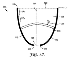
図1A及び図1Bは、反射性又は半透過性の外側主面110を含む照明構成要素100の断面図及び上面図をそれぞれ示しており、この外側主面は、遠位端部113及び近位端部116、出力主面120、光注入領域123、光学容積126、及び光学容積126内に配設された切り替え可能な拡散体130を有している。切り替え可能な拡散体130は、面法線131を有する。本明細書で使用されるとき、遠位及び近位という用語は、光注入領域に対する位置を指す。出力主面120は、反射性又は半透過性の外側主面110の遠位端部113に隣接する遠位面である。光注入領域123は、反射性又は半透過性の外側主面110の近位端部116に隣接している。図示の実施形態では、光注入領域123は、光学容積の入力面である。他の実施形態では、光注入領域123は、光源(単数又は複数)、及び/又はレンズ(単数又は複数)などの光学素子を含む、近位端部116に隣接する容積である。光源は、1つ以上の発光ダイオード(LED)を含んでもよく、光学容積126内に延在することができる。図示の実施形態では、切り替え可能な拡散体130は、完全に光学容積126内に配設されている。他の実施形態では、切り替え可能な拡散体は、光学容積内に部分的にのみ配設されてもよい。出力主面120は、遠位端部113によって画定された平面とすることができる。例えば、出力主面120は、遠位端部113によって囲まれた平面領域であってもよい。同様に、光注入領域123は、近位端部116によって画定された平面とすることができる。例えば、光注入領域123は、近位端部116によって囲まれた平面領域であってもよい。
1A and 1B show a cross-sectional view and a top view, respectively, of a
照明構成要素100は、平均光出力の方向と一致し得る光軸189を有する。いくつかの実施形態では、平均光出力の方向は、照明構成要素100の対称軸によって決定される。いくつかの実施形態では、切り替え可能な拡散体130及び/又は反射性又は半透過性の外側主面110は非対称であり、平均光出力の方向は切り替え可能な拡散体130の状態に左右され得る。いくつかの実施形態では、光学容積126の遠位面である出力主面120は、切り替え可能な拡散体130が実質的に空間的に一様な状態(実質的に透明な状態であってもよい)にある場合、光学容積126の平均光出力の方向に対して実質的に直交している。いくつかの実施形態では、出力主面120は、光軸189に対して実質的に直交している。いくつかの実施形態では、切り替え可能な拡散体130は、その少なくとも一部において、光軸189に平行ではない面法線131を含んでいる。これは、切り替え可能な拡散体が図1Aに例示するような湾曲形状を有する場合、あるいは、光軸189に対して角度αで照明構成要素100内に配設された平坦な切り替え可能な拡散体を用いると、起こり得るものである。面法線131と光学容積126の光軸189との間の角度αは、切り替え可能な拡散体の少なくともいくつかの部分で、10度より大きくてもよく、又は20度より大きくてもよく、又は30度より大きくてもよく、かつ、90度以下であってもよい。90度を超える角度は、90度未満の余角に相当するので、0度から90度までの角度だけを考慮すればよい。
The
いくつかの実施形態では、反射性又は半透過性の外側主面110は、一様又は実質的に一様な反射率及び/又は透過率を有してもよく、他の実施形態では、反射性又は半透過性の外側主面110は、面に沿って変化する反射及び/又は透過の特性を有してもよい。この変化は、実質的に連続的とすることができ、あるいは、別個の領域は、異なる反射及び/又は透過の特性を有することができる。例えば、領域110a及び領域110bは、異なる反射及び/又は透過の特性を有してもよい。かかる特性は、異なる全体的な反射率及び/又は透過率、及び/又は異なる波長依存性の反射率及び/又は透過率、及び/又は異なる偏光依存性の反射率及び/又は透過率、を含み得る。例えば、透過率に対する反射率の比率は、空間的に変化することがある。反射率及び/又は透過率は、可視光線、近赤外光又は紫外線光に適用してもよい。反射性又は半透過性の外側主面110の形状及び/又は反射及び/又は透過の特性は、切り替え可能な拡散体を第1の状態から第2の状態に切り替えることによって、照明構成要素100からの光出力の角度分布及び/又はスペクトル分布及び/又は偏光分布を変化させるように、選択することができる。この形状は、例えば、可変の面法線を有する分割された面又は切子面を提供することによって、調整してもよい。かかる切子面は、別の所で更に説明する。反射性又は半透過性の外側主面110の反射及び/又は透過の特性はまた、表面のテクスチャを変化させることによって、調整することができる。例えば、反射性又は半透過性の外側主面110は、空間的に変化する拡散の反射率又は透過率を提供する空間的に変化するテクスチャを有することができる。例えば、いくつかの実施形態では、反射性又は半透過性の外側主面110は、空間的に変化する、鏡面反射率に対する拡散反射率の比率を提供する。
In some embodiments, the reflective or translucent outer
本明細書の任意の実施形態では、反射性又は半透過性の外側主面は、反射性又は半透過性のフィルムを使用して形成することができる。好適な反射性又は半透過性のフィルムは、米国特許第5,882,774号(Jonzaら)、同第6,179,948号(Merrillら)及び同第6,783,349号(Neavinら)に記載されているような複数の交互複屈折ポリマー層を含む、多層光学フィルム(MOF)を備えている。異なる反射及び/又は透過の特性は、MOFであり得る有孔の反射性又は半透過性のフィルムを使用することによって、実現することができ、有孔密度は、反射性又は半透過性の外側主面に沿って変化する。例えば、反射性又は半透過性の外側主面110は、領域110a及び110bにおいて異なる有孔密度を有する有孔の反射性又は半透過性のフィルムを備えることができる。有孔の反射性又は半透過性のフィルムは、例えば、有孔反射体フィルム又は有孔反射型偏光子であってもよい。有孔反射体フィルムは、「Enhanced Specular Reflector」(3M社から入手可能)などの広帯域反射体であってもよく、あるいは、反射特性が波長に依存するように、いくつかの波長帯域でのみ反射してもよい。好適な反射型偏光子としては、DBEF(3M社から入手可能)が挙げられる。他の好適な反射性又は半透過性のフィルムには、Transflective Display Film(3M社から入手可能)が含まれる。
In any embodiment herein, the reflective or translucent outer major surface can be formed using a reflective or translucent film. Suitable reflective or translucent films are described in US Pat. Nos. 5,882,774 (Jonza et al.), 6,179,948 (Merrill et al.), And 6,783,349 (Neavin et al.). A multilayer optical film (MOF) comprising a plurality of alternating birefringent polymer layers as described in 1). Different reflective and / or transmissive properties can be achieved by using a perforated reflective or semi-transparent film, which can be MOF, and the perforated density is outside of the reflective or semi-transmissive It changes along the main surface. For example, the reflective or translucent outer
いくつかの実施形態では、基板に取り付けられた1つ以上のMOF層を有する透明基板を使用して、反射性又は半透過性の外側主面110が形成される。いくつかの実施形態では、1つ以上のMOF層を2つの基板の間に配設することができる。かかる実施形態では、MOF層は、光学容積の外側境界を画定するものとして理解され、2つの基板層のうちの1つは、MOF層によって確立された光学容積の外にあると考えられ得る。領域110a及び110bは、異なるMOF層を備えることができる。MOF層としては、広帯域反射体、波長依存反射体、反射型偏光子、非対称反射体(第1の偏光に直交する第2の偏光より多くの第1の偏光を反射する反射体)、又はそれらの組み合わせを挙げることができる。
In some embodiments, a reflective or semi-transparent outer
他の反射体又は半透過反射体としては、金属(例えば、アルミニウム)の反射体又は半透過反射体、物理蒸着によって作られた反射体又は半透過反射体、マトリックス中に粒子(例えば、ポリマーマトリックス中の反射粒子)を有する反射体又は半透過反射体、孔質反射体又は半透過反射体(例えば、拡散反射体を提供するために空隙を含むポリマーマトリックス中の反射粒子)、あるいは、全反射(TIR)を提供する反射体又は半透過反射体、を挙げることができるが、これらに限定されるものではない。ポリエステルマトリックス中に粒子を含む好適な孔質反射体は、例えば、米国特許第7,273,640号(Laneyら)に記載されている。 Other reflectors or transflective reflectors include metal (eg, aluminum) reflectors or transflective reflectors, reflectors or transflective reflectors made by physical vapor deposition, particles in a matrix (eg, polymer matrix) Reflector or semi-transparent reflector with a reflective particle in it), a porous reflector or a semi-transparent reflector (eg, a reflective particle in a polymer matrix containing voids to provide a diffuse reflector), or total reflection Non-limiting examples include reflectors or transflective reflectors that provide (TIR). Suitable porous reflectors containing particles in a polyester matrix are described, for example, in US Pat. No. 7,273,640 (Laney et al.).
本明細書に記載された照明構成要素のいずれも、空間的に変化する反射特性を有する反射性又は半透過性の外側主面を備えることができる。例えば、透過率に対する反射率の比率は、空間的に変化してもよい。いくつかの実施形態では、空間的に変化する反射特性としては、対象の波長帯域内の非偏光の1つ以上の反射性、この波長帯域における第1の偏光状態を有する偏光の反射性、この波長帯域における非偏光の拡散反射率、及び、この波長帯域における第1の偏光状態を有する偏光の拡散反射率、が挙げられる。対象のこの波長帯域は、可視波長帯域(例えば、380nm〜780nmの範囲の波長)であってもよいし、あるいは、近赤外線(IR)若しくは紫外(UV)帯域であってもよいし、あるいは、可視、IR及びUVの範囲のうちの1つ以上と重なる帯域であってもよい。近赤外線は、例えば、780nm〜2000nmの範囲の波長を指し得る。 Any of the lighting components described herein can comprise a reflective or translucent outer major surface with spatially varying reflective properties. For example, the ratio of reflectance to transmittance may vary spatially. In some embodiments, the spatially varying reflection characteristics include one or more non-polarized reflectivity within the wavelength band of interest, the reflectivity of polarized light having a first polarization state in this wavelength band, Non-polarized diffuse reflectance in the wavelength band, and diffuse reflectance of polarized light having the first polarization state in this wavelength band. This wavelength band of interest may be a visible wavelength band (e.g., a wavelength in the range of 380 nm to 780 nm), or may be a near infrared (IR) or ultraviolet (UV) band, or It may be a band that overlaps one or more of the visible, IR and UV ranges. Near-infrared can refer to wavelengths in the range of 780 nm to 2000 nm, for example.
本明細書に記載の照明構成要素のいずれかからの光出力は、切り替え可能な拡散体が、第1の状態から、第1の状態とは異なる第2の状態に変化した場合に、異なる出力角度分布、異なる出力スペクトル分布(例えば、異なる色出力)、異なる偏光出力分布、又はこれらの組み合わせ、を有することができる。 The light output from any of the lighting components described herein is different when the switchable diffuser changes from a first state to a second state that is different from the first state. It can have an angular distribution, a different output spectral distribution (eg, different color output), a different polarization output distribution, or a combination thereof.
いくつかの実施形態では、照明構成要素100は、切り替え可能な拡散体130を除いて実質的に中空である。いくつかの実施形態では、照明構成要素100は、切り替え可能な拡散体130を除いて、実質的に一体型である。本明細書の照明構成要素のいずれも、切り替え可能な拡散体、任意の追加の拡散体、光注入領域内の任意の光学素子(例えば、レンズ若しくはLED)を除いて、実質的に中空又は実質的に一体型とすることができる。
In some embodiments, the
いくつかの実施形態では、光学容積は、例えば、円錐を生成するように単一の方向に湾曲し得る単一の反射性又は半透過性の外側主面を含むか、あるいは、図1A及び図1Bに示すように、例えば、軸の周りに回転曲面を生成するために2つの方向に湾曲していてもよい。いくつかの実施形態では、回転曲面は複合曲線であり、例えば、軸周りの複数の曲線の回転によって生成することができる。いくつかの実施形態では、光学容積は、2つ以上の反射性又は半透過性の外側主面を備えることができる。少なくとも1つの反射性又は半透過性の外側主面は、共通平面内にすべてではない2つ以上の平面を含んでもよいし、あるいは、一方向に湾曲した、若しくは2方向に湾曲した1つ以上の面を含んでもよい。 In some embodiments, the optical volume includes a single reflective or semi-transparent outer major surface that can be curved in a single direction, for example, to create a cone, or FIG. 1A and FIG. As shown in 1B, for example, it may be curved in two directions to generate a rotating curved surface around the axis. In some embodiments, the rotating surface is a compound curve and can be generated, for example, by rotation of multiple curves about an axis. In some embodiments, the optical volume can comprise two or more reflective or semi-transmissive outer major surfaces. The at least one reflective or translucent outer major surface may include two or more, but not all, planes in a common plane, or one or more curved in one direction or curved in two directions May be included.
光注入領域から光学容積内に注入され、ある面に入射する、対象とする波長帯域の光エネルギーの大部分をその面が反射する場合、その表面は反射性として説明することができる。例えば、ある反射面は、その面に入射して光注入領域から光学容積に注入される光エネルギーの少なくとも約70パーセント、又は少なくとも約80パーセント、又は少なくとも約90パーセントを反射することができる。別の所で説明するように、対象の波長帯域は、可視、IR及び/又はUVの範囲の光を含んでもよい。光注入領域から光学容積内に注入され、ある表面に入射する、対象の波長帯域の光エネルギーの一部を反射して一部を透過させる場合、その表面は半透過性として説明することができる。例えば、半透過面は、その面に入射して光注入領域から光学容積に注入される光エネルギーの10%〜90%の範囲で反射し、その面に入射して光注入領域から光学容積に注入される光エネルギーの10%〜90%の範囲で透過させてもよい。半透過面は、その面に入射して、光注入領域から光学容積に注入される光エネルギーの相当の部分を、別の所で説明するような全反射の機能(TIR)によって、反射することができる。 If the surface reflects most of the light energy in the wavelength band of interest that is injected into the optical volume from the light injection region and incident on a surface, the surface can be described as reflective. For example, a reflective surface can reflect at least about 70 percent, or at least about 80 percent, or at least about 90 percent of the light energy incident on the surface and injected from the light injection region into the optical volume. As described elsewhere, the wavelength band of interest may include light in the visible, IR and / or UV range. A surface can be described as semi-transmissive if it reflects a portion of the light energy in the wavelength band of interest that is injected into the optical volume from the light injection region and incident on the surface and transmits a portion of it. . For example, the semi-transmissive surface is reflected in the range of 10% to 90% of the light energy incident on the surface and injected from the light injection region into the optical volume, and is incident on the surface to enter the optical volume from the light injection region. You may permeate | transmit in the range of 10%-90% of the light energy injected. A transflective surface is incident on that surface and reflects a substantial portion of the light energy injected from the light injection region into the optical volume by a total internal reflection function (TIR) as described elsewhere. Can do.
本明細書で使用されるとき、光学容積の主面は、光学容積の境界の総面積の少なくとも約5パーセント(又は少なくとも約7パーセント、又は少なくとも約10パーセント、又は少なくとも約15パーセント、又は少なくとも約20パーセント)を構成する面であるか、あるいは、光学容積の光注入領域に光を注入すると、光学容積から出力される光エネルギー(可視光、近赤外線及び紫外光のエネルギーのうちの1つ以上を含んでもよい)の少なくとも約5%(又は少なくとも約7パーセント、又は少なくとも約10パーセント、又は少なくとも約15パーセント、又は少なくとも約20パーセント)がその面を通って出力されるように、光学容積の主面は配設される。いくつかの場合には、光学容積の境界は、フィルムの縁部を含むことができる。かかる縁部は、境界の総面積の2又は3パーセント未満を構成し、小さな光出力(例えば、光学容積から出力される光エネルギーの2又は3パーセント未満)を提供することができる。かかる面は、副次的な面であり、主面ではないと考えられる。いくつかの実施形態では、照明構成要素は、出力主面を備え、照明構成要素の光学容積内に少なくとも部分的に配設された切り替え可能な拡散体が第1の状態にある場合、光学容積から出力される光エネルギーの少なくとも約40パーセント、又は少なくとも約50パーセント、又は少なくとも約60パーセント、又は少なくとも約70パーセントが、出力主面を通して出力される。 As used herein, the major surface of the optical volume is at least about 5 percent (or at least about 7 percent, or at least about 10 percent, or at least about 15 percent, or at least about the total area of the boundary of the optical volume. 20%), or when light is injected into the light injection region of the optical volume, one or more of light energy (visible light, near infrared light, and ultraviolet light energy) output from the optical volume Of the optical volume such that at least about 5% (or at least about 7 percent, or at least about 10 percent, or at least about 15 percent, or at least about 20 percent) is output through the surface. The main surface is disposed. In some cases, the optical volume boundary may include the edge of the film. Such an edge may constitute less than 2 or 3 percent of the total area of the boundary and provide a small light output (eg, less than 2 or 3 percent of the light energy output from the optical volume). This aspect is a secondary aspect and not a main aspect. In some embodiments, the illumination component comprises an output volume when the switchable diffuser comprises an output major surface and is disposed at least partially within the optical volume of the illumination component in a first state. At least about 40 percent, or at least about 50 percent, or at least about 60 percent, or at least about 70 percent of the light energy output from is output through the output major surface.
本明細書の照明構成要素に使用される切り替え可能な拡散体は、構造化表面を有してもよく、あるいは、切り替え可能な拡散体に取り付けられた構造化層を含んでもよい。かかる場合、切り替え可能な拡散体の面法線は、構造化層の形状の法線ベクトルではなく、切り替え可能な拡散体の全体的形状の法線ベクトルを指している。切り替え可能な拡散体が液晶層を含む実施形態では、面法線は、液晶層の面に適用され、例えば、液晶層に隣接する層に形成され得る任意の微細構造面には適用されない。 The switchable diffuser used in the lighting components herein may have a structured surface or may include a structured layer attached to the switchable diffuser. In such a case, the surface normal of the switchable diffuser refers to the normal vector of the overall shape of the switchable diffuser, not the normal vector of the structured layer shape. In embodiments where the switchable diffuser includes a liquid crystal layer, the surface normal is applied to the surface of the liquid crystal layer, and not to any microstructured surface that can be formed in a layer adjacent to the liquid crystal layer, for example.
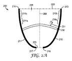
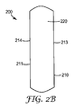
図2A及び図2Bは、第1及び第2の反射性又は半透過性の外側主面210及び211を含む照明構成要素200の断面図及び上面図をそれぞれ示す。第1の反射性又は半透過性の外側主面210は、第1の遠位端部213及び第1の近位端部216を備え、第2の反射性又は半透過性の外側主面211は、第2の遠位端部214及び第2の近位端部217を備えている。照明構成要素200はまた、出力主面220、光注入領域223、光学容積226、及び光学容積226内に配設された切り替え可能な拡散体230を備えている。切り替え可能な拡散体230は面法線231を有する。照明構成要素200は、光軸289を有し、切り替え可能な拡散体230の少なくとも一部は、光軸289に平行ではない面法線231を有する。面法線231と光軸289との間の角度αは、切り替え可能な拡散体230の少なくともいくつかの部分で、10度より大きくてもよく、20度より大きくてもよく、又は30度より大きくてもよく、かつ、90度以下であってもよい。出力主面220は、第1の遠位端部213及び第2の遠位端部214に隣接する遠位面である。光注入領域223は、第1の近位端部216及び第2の近位端部217に隣接している。図示の実施形態では、光注入領域223は光学容積の入力面である。他の実施形態では、光注入領域223は、光源、及び/又はレンズ若しくはLEDなどの光学素子、を含む第1及び第2の近位端部216及び217に隣接する容積である。図示の実施形態では、切り替え可能な拡散体230は、完全に光学容積226内に配設されている。他の実施形態では、切り替え可能な拡散体は、光学容積内に部分的にのみ配設されてもよい。第1及び第2の反射性又は半透過性の外側主面210及び211は、一方向に湾曲し、直交方向に実質的に平坦である。
2A and 2B show a cross-sectional view and a top view, respectively, of a
出力主面220は、第1及び第2の遠位端部213及び214によって画定された平面にすることができる。例えば、出力主面220は、第1及び第2の遠位端部213及び214によって実質的に囲まれた平面領域であってもよい。同様に、光注入領域223は、第1及び第2の近位端部216及び217によって画定された平面であってもよい。例えば、光注入領域223は、第1及び第2の近位端部216及び217によって実質的に囲まれた平面領域であってもよい。
The output
いくつかの実施形態では、第1及び第2の反射性又は半透過性の外側主面210及び211は、一様な又は実質的に一様な反射率及び/又は透過率を有することができ、他の実施形態では、第1及び第2の反射性又は半透過性の外側主面210及び211は、面に沿って変化する反射及び/又は透過の特性を有することができる。この変化は、実質的に連続的とすることができるか、あるいは、別個の領域が異なる反射及び/又は透過の特性を有することができる。例えば、領域210a、210b、211a、及び/又は211bは、異なる反射及び/又は透過の特性を有することができる。異なる反射及び/又は透過の特性は、例えば、別の所で説明するようなMOFフィルムを使用して、実現することができる。第1及び第2の反射性又は半透過性の外側主面210及び211の形状及び/又は反射及び/又は透過の特性は、切り替え可能な拡散体230を第1の状態から第2の状態に切り替えることによって、照明構成要素200からの光出力の角度分布及び/又はスペクトル分布及び/又は偏光分布を変化させるように、選択することができる。
In some embodiments, the first and second reflective or semi-transmissive outer
いくつかの実施形態では、照明構成要素200は、切り替え可能な拡散体230を除いて、実質的に中空である。いくつかの実施形態では、照明構成要素200は、切り替え可能な拡散体230を除いて、実質的に一体型である。
In some embodiments, the
いくつかの実施形態では、光軸289は、照明構成要素200の対称方向により決定される。いくつかの実施形態では、平均光出力の方向は、光軸289と一致する。いくつかの実施形態では、切り替え可能な拡散体230及び/又は反射性又は半透過性の外側主面210及び/又は211は、非対称であり、平均光出力の方向は切り替え可能な拡散体230の状態に左右され得る。いくつかの実施形態では、光学容積226の遠位面である出力主面220は、切り替え可能な拡散体230が第1の状態(実質的に透明な状態であってもよい)にある場合、光軸289に対して実質的に直交しており、及び/又は、光学容積226の平均光出力の方向に対して実質的に直交している。
In some embodiments, the
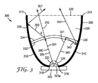
図3は、少なくとも1つの遠位端部313と少なくとも1つの近位端部316とを有する少なくとも1つの反射性又は半透過性の外側主面310、出力主面320、光注入領域323、レンズ構成要素324、光源325、光学容積326、及び光学容積326内に配設された切り替え可能な拡散体330、を含む照明構成要素300の断面図を示す。光源325は、1つ以上の個別の照明素子(例えば、1つ以上のLED)を含み、光学容積326内に延在することができる。切り替え可能な拡散体330は、第1主面332及び第2主面334を備える。出力主面320は、少なくとも1つの反射性又は半透過性の外側主面310の少なくとも1つの遠位端部313に隣接する遠位面である。光注入領域323は、少なくとも1つの反射性又は半透過性の外側主面310の少なくとも1つの近位端部316に隣接している。図示の実施形態では、光注入領域323は、レンズ構成要素324を含む容積である。光注入領域323は、入力面323aを含むことができる。いくつかの実施形態では、光注入領域323は、少なくとも1つの近位端部316に隣接する入力面323aであり、レンズ構成要素324は、光学容積326の外側に配置されている。図示の実施形態では、切り替え可能な拡散体330は、完全に光学容積326内に配設されている。他の実施形態では、切り替え可能な拡散体は、光学容積内に部分的にのみ配設されてもよい。切り替え可能な拡散体330は、切り替え可能な拡散体330の一部に、光軸に平行ではなく、かつ/又は照明構成要素300の対称軸であり得る光出力の平均方向に平行ではない、面法線を有する。出力主面320は、少なくとも1つの遠位端部313によって画定された平面とすることができる。例えば、出力主面320は、少なくとも1つの遠位端部313によって囲まれた平面領域であってもよい。同様に、入力面323aは、少なくとも1つの近位端部316によって画定される平面であってもよい。例えば、入力面323aは、少なくとも1つの近位端部316によって囲まれた平面領域であってもよい。
FIG. 3 illustrates at least one reflective or translucent outer
少なくとも1つの反射性又は半透過性の外側主面310は、切り替え可能な拡散体330を挟んで光注入領域323の反対側の部分336を含む。部分336は、切り替え可能な拡散体330から少なくとも1つの遠位端部313まで延在している。いくつかの実施形態では、少なくとも1つの反射性又は半透過性の外側主面310は単一の面(図1A及び図1Bの面110に対応する)であり、いくつかの実施形態では、少なくとも1つの反射性又は半透過性の外側主面310は、2つの面(図2A及び図2Bの面210及び211に対応する)である。他の実施形態では、少なくとも1つの反射性又は半透過性の外側主面310は、3つ以上の面を含む。部分336は、単一の面、2つの面、又は3つ以上の面であってもよい。
The at least one reflective or translucent outer
照明構成要素300は、第1、第2及び第3のセグメント341、342及び343を含む光路340を備えている。第1のセグメント341は、光注入領域323から第1主面332を通って第2主面334まで延在し、そこで、第2のセグメント342として反射される。第2のセグメント342は、第1主面332を通過して戻り、少なくとも1つの反射性又は半透過性の外側主面310から第3のセグメント343として反射し、出力主面320を通って光学容積326を出て行く。光路340は、光注入領域323から出力主面320まで延在し、切り替え可能な拡散体330を通る複数の経路を含む。光路340は、出力主面320からのいかなる反射も含まず、光学容積326の外側の領域から光学容積326に入るいかなる部分又はセグメントも含まない。いくつかの実施形態では、光学容積326は、実質的に光学的に透明な材料で充填される。かかる実施形態では、別の光路は、出力主面320からの反射を含むことができる。いくつかの実施形態では、光学容積326の外側に配置された物体は、照明構成要素300から出力された光を、出力主面320を通して、照明構成要素300の中に反射して戻すことができる。かかる実施形態では、照明構成要素300は、光注入領域323から、切り替え可能な拡散体330を通る複数の経路を含む出力主面320までの光路340をなお含み、この光路は出力主面320からの反射を含まず、出力主面320を通って光学容積326に入るいかなる部分も含まない。
The
照明構成要素300はまた、第1及び第2のセグメント351及び352を含む光路350を備え、第1のセグメント351を含んで第2のセグメント356及び第3のセグメント357を含む光路355を備えている。光路350は、光注入領域323から始まり、出力主面320を通って延在する。光路350は、出力主面320からのいかなる反射も含まず、光学容積326の外側の領域から出力主面320を通って光学容積326に入るいかなる部分又はセグメントも含まず、切り替え可能な拡散体330からの後方散乱も含まない。第1のセグメント351は、光注入領域323から開始し、切り替え可能な拡散体330で終了する。光注入領域が入力面であり、光源が入力面を通って光を注入するように構成されている実施形態では、第1のセグメントは、光源から開始し、入力面を通って延在すると理解することができる。光路350の場合、第1のセグメント351は、実質的に散乱することなく、第2のセグメント352として、切り替え可能な拡散体を透過する。これは、例えば、切り替え可能な拡散体が、第1のヘイズによって特徴付けることができる第1の状態にある場合に発生し得る。いくつかの実施形態では、第1の状態は実質的に透明な状態であり、第1のヘイズは実質的にゼロである。光路355の場合、第1のセグメント351は、それが切り替え可能な拡散体330を透過するときに散乱角θで散乱されて第2のセグメント356になり、少なくとも1つの反射性又は半透過性の外側主面310から、第3のセグメント357として反射される。切り替え可能な拡散体330による光路355の散乱は、例えば、切り替え可能な拡散体が、第1のヘイズとは異なる第2のヘイズによって特徴付けられ得る第2の状態にある場合に、生じる可能性がある。例えば、第2のヘイズは、第1のヘイズよりも著しく大きくすることができる。光路は、切り替え可能な拡散体によって90度より大きい角度θで散乱される場合、切り替え可能な拡散体330からの後方散乱を含むと言うことができる。光路355は後方散乱を含まないが、他の光路は後方散乱を含み得る。
The
いくつかの実施形態では、少なくとも1つの反射性又は半透過性の外側主面310は、一様又は実質的に一様な反射率及び/又は透過率を有することができ、他の実施形態では、少なくとも1つの反射性又は半透過性の外側主面310は、面に沿って変化する反射及び/又は透過の特性を有することができる。この変化は、別の所で説明するように、実質的に連続的とすることができるか、あるいは、別個の領域が異なる反射及び/又は透過の特性を有することができる。少なくとも1つの反射性又は半透過性の外側主面310の形状及び/又は反射及び/又は透過の特性は、切り替え可能な拡散体330を第1の状態から第2の状態に切り替えることによって、照明構成要素300からの光出力の角度分布及び/又はスペクトル分布及び/又は偏光分布を変化させるように、選択することができる。
In some embodiments, at least one reflective or translucent outer
図4は、少なくとも1つの遠位端部413と少なくとも1つの近位端部416とを有する少なくとも1つの反射性又は半透過性の外側主面410、出力主面420、光注入領域423、レンズ構成要素424、光源425、光学容積426、及び光学容積426内に少なくとも部分的に配設された切り替え可能な拡散体430、を含む照明構成要素400の断面図を示す。切り替え可能な拡散体430は、第1主面432及び第2主面434を備える。出力主面420は、少なくとも1つの反射性又は半透過性の外側主面410の少なくとも1つの遠位端部413に隣接する遠位面である。光注入領域423は、反射性又は半透過性の外側主面410の少なくとも1つの近位端部416に隣接している。図示の実施形態では、光注入領域423は、レンズ構成要素424を含む容積である。光注入領域423は、入力面423aを含むことができる。いくつかの実施形態では、光注入領域423は、少なくとも1つの近位端部416に隣接する入力面423aであり、光源425及びレンズ構成要素424は、光学容積426の外側に配置されている。いくつかの実施形態では、光源425は、1つ以上の個別の照明素子(例えば、1つ以上のLED)を含み、光学容積426内に延在することができる。図示の実施形態では、切り替え可能な拡散体430は、光学容積426内に部分的に配設される。他の実施形態では、切り替え可能な拡散体を光学容積内に完全に配設することができる。出力主面420は、少なくとも1つの遠位端部413によって画定された平面であってもよく、入力面423aは、少なくとも1つの近位端部416によって画定される平面であってもよい。
FIG. 4 shows at least one reflective or translucent outer
切り替え可能な拡散体430を実質的に垂直に配設することによって、その面法線431は、切り替え可能な拡散体430が実質的に透明な状態にある場合の平均光出力の方向にあり得る光軸489に対して、実質的に垂直となる。他の実施形態では、切り替え可能な拡散体430は、光軸489に対してあるスキュー角(即ち、0度又は90度以外のある角度)で配設してもよい。
By arranging the
いくつかの実施形態では、少なくとも1つの反射性又は半透過性の外側主面410は単一の面(図1A及び図1Bの面110に対応する)であり、いくつかの実施形態では、少なくとも1つの反射性又は半透過性の外側主面410は、2つの面(図2A及び図2Bの面210及び211に対応する)である。他の実施形態では、少なくとも1つの反射性又は半透過性の外側主面410は、3つ以上の面を含む。
In some embodiments, the at least one reflective or translucent outer
図4に示すように、照明構成要素400は、第1及び第2のセグメント441及び442を含む光路440を備えている。第1のセグメント441は、光注入領域423から第1主面432及び第2主面434を通って、少なくとも1つの反射性又は半透過性の外側主面410まで延在し、そこで、第2のセグメント442として反射される。第2のセグメント442は、第2主面434及び第1主面432を通過し、続いて、出力主面420を透過する。光路440は、光注入領域423から出力主面420まで延在し、切り替え可能な拡散体430を通る複数(この場合は2つ)の経路を含んでいる。光路440は、出力主面420からのいかなる反射も含まず、光学容積426の外側の領域から光学容積426に入るいかなる部分又はセグメントも含まない。光路440は、切り替え可能な拡散体430からのフレネル表面反射を含まない。いくつかの実施形態では、光学容積426は、実質的に光学的に透明な材料で充填される。かかる実施形態では、別の光路は、出力主面420からの反射を含むことができる。いくつかの実施形態では、光学容積426の外側に配置された物体は、照明構成要素400から出力された光を、出力主面420を通して、照明構成要素400の中に反射して戻すことができる。かかる実施形態では、照明構成要素400は、光注入領域423から、切り替え可能な拡散体430を通る複数の経路を含む出力主面420までの光路440をなお含み、この光路は出力主面420からのいかなる反射も含まず、出力主面420を通って光学容積426に入るいかなる部分も含まない。
As shown in FIG. 4, the
いくつかの実施形態では、少なくとも1つの反射性又は半透過性の外側主面410は、一様又は実質的に一様な反射率及び/又は透過率を有することができ、他の実施形態では、少なくとも1つの反射性又は半透過性の外側主面410は、別の所で説明するように、面に沿って変化する反射及び/又は透過の特性を有することができる。少なくとも1つの反射性又は半透過性の外側主面410の形状及び/又は反射及び/又は透過の特性は、切り替え可能な拡散体430を第1の状態から第2の状態に切り替えることによって、照明構成要素400からの光出力の角度分布及び/又はスペクトル分布及び/又は偏光分布を変化させるように、選択することができる。
In some embodiments, the at least one reflective or translucent outer
いくつかの実施形態では、照明構成要素400は、切り替え可能な拡散体430及びレンズ構成要素424を除いて、実質的に中空である。いくつかの実施形態では、照明構成要素400は、切り替え可能な拡散体430及びレンズ構成要素424を除いて実質的に一体型である。
In some embodiments, the
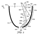
図5は、少なくとも1つの遠位端部513と少なくとも1つの近位端部516とを有する少なくとも1つの反射性又は半透過性の外側主面510、出力主面520、光注入領域523、光学容積526、及び光学容積526内に少なくとも部分的に配設された切り替え可能な拡散体530、を含む照明構成要素500の断面図を示す。切り替え可能な拡散体530は、第1主面532及び対向する第2主面534を備える。出力主面520は、少なくとも1つの反射性又は半透過性の外側主面510の少なくとも1つの遠位端部513に隣接する遠位面である。光注入領域523は、反射性又は半透過性の外側主面510の少なくとも1つの近位端部516に隣接している。図示の実施形態では、光注入領域523は入力面である。他の実施形態では、光注入領域は、別の所で説明するように、レンズ構成要素を含むことができる容積である。出力主面520は、少なくとも1つの遠位端部513によって画定された平面であってもよく、光注入領域523は、少なくとも1つの近位端部516によって画定される平面であってもよい。
FIG. 5 illustrates at least one reflective or translucent outer
いくつかの実施形態では、少なくとも1つの反射性又は半透過性の外側主面510は単一の面(図1A及び図1Bの面110に対応する)であり、いくつかの実施形態では、少なくとも1つの反射性又は半透過性の外側主面510は、2つの面(図2A及び図2Bの面210及び211に対応する)である。他の実施形態では、少なくとも1つの反射性又は半透過性の外側主面510は、3つ以上の面を含む。
In some embodiments, the at least one reflective or translucent outer
光線550は、光注入領域523に注入され、切り替え可能な拡散体530の第1の領域530aを通過し、少なくとも1つの反射性又は半透過性の外側主面510のゾーン510aから反射し、切り替え可能な拡散体530の第3の領域530cを透過し、出力主面520を通って照明構成要素500を出て行く。光線555は、光注入領域523に注入され、切り替え可能な拡散体530の第2の領域530bを通過し、少なくとも1つの反射性又は半透過性の外側主面510のゾーン510bから反射し、切り替え可能な拡散体530の第4の領域530dを透過し、出力主面520を通って照明構成要素500を出て行く。
いくつかの実施形態では、少なくとも1つの反射性又は半透過性の外側主面510は、一様又は実質的に一様な反射率及び/又は透過率を有することができ、他の実施形態では、少なくとも1つの反射性又は半透過性の外側主面510は、別の所で説明するように、面に沿って変化する反射及び/又は透過の特性を有することができる。この変化は、実質的に連続的とすることができるか、あるいは、別個のゾーンが異なる反射及び/又は透過の特性を有することができる。例えば、ゾーン510a、ゾーン510b、及びゾーン510cは、異なる反射及び/又は透過の特性を有することができる。かかる特性は、光(可視光、UV光及び/又はIR光であってもよい)の異なる全体的な反射率及び/又は透過率を含んでもよいし、あるいは、異なる波長依存の反射率及び/又は透過率を含んでもよいし、あるいは、異なる拡散反射度又は透過度(例えば、異なる表面散乱)を含んでもよい。この拡散反射度は、実質的に拡散反射成分を伴わない鏡面反射から、実質的に鏡面反射成分を伴わない拡散反射(例えば、ランバート反射)まで変化し、部分的に拡散し、部分的に鏡面であると記述できる半鏡面反射を含み得る。少なくとも1つの反射性又は半透過性の外側主面510の形状及び/又は反射及び/又は透過の特性は、切り替え可能な拡散体530の状態を切り替えることによって、照明構成要素500からの光出力の角度分布及び/又はスペクトル分布及び/又は偏光分布を変化させるように、選択することができる。
In some embodiments, at least one reflective or translucent outer
切り替え可能な拡散体530は、第1〜第4の独立してアドレス可能な領域530a〜530dを含む。切り替え可能な拡散体の領域を好適に選択することによって、及び/又は少なくとも1つの反射性又は半透過性の外側主面の幾何学的形状及び/又は反射及び/又は透過の特性を選択することによって、照明構成要素500の光出力は、有用に調節可能な光出力を備えることができる。光出力の角度分布、スペクトル分布、及び偏光分布のいずれか又はすべては、切り替え可能な拡散体530の各々独立してアドレス可能な領域の状態を変更することによって、調整することができる。
切り替え可能な拡散体530は、任意の数の独立してアドレス可能な領域を有してもよく、少なくとも1つの反射性又は半透過性の外側主面510は、任意の数のゾーンを有してもよい。いくつかの実施形態では、切り替え可能な拡散体530の独立してアドレス可能な領域及び少なくとも1つの反射性又は半透過性の外側主面510のゾーンは対応していてもよい。即ち、切り替え可能な拡散体530の領域を通って注入された光は、少なくとも1つの反射性又は半透過性の外側主面510のあるゾーンに主に入射することができる。例えば、領域530aを通って注入された光は、主にゾーン510aに入射する。領域530bを通って注入された光は主にゾーン510bに入射する。そして、領域530cを通って注入された光は主にゾーン510cに入射する。ゾーンは必ずしも1対1の対応を持たない領域に対応していてもよい。例えば、領域530dを通って注入された光は、実質的に少なくとも1つの反射性又は半透過性の外側主面510と相互作用することなく、照明構成要素500を出て行く可能性がある。いくつかの実施形態では、ゾーンは領域と1対1で対応し、他の実施形態では、複数のゾーンは単一の領域に対応してもよく、複数の領域は単一のゾーンに対応してもよい。
The
いくつかの実施形態では、切り替え可能な拡散体530が低ヘイズ又は実質的に透明な状態にある場合、少なくとも1つの反射性又は半透過性の外側主面510は、ゾーン510a、510b及び510cが、光注入領域523からの光を第1、第2及び第3の平均方向に反射するように、形づくることができる。ヘイズ状態に置くために切り替え可能な拡散体530の領域を選択することによって、いくつかの方向の光出力分布を変化させることができ、他の方向の光出力分布は実質的に変化しないか又は僅かにしか変化しない。例えば、第1領域530aがヘイズ状態に置かれた場合、第1の平均方向に向けられた光出力分布は変化する可能性があり、第1の平均方向に向けられたであろう一部の光が第3の平均方向に散乱され得る点を除いて、第3の平均方向の出力はほとんど影響を受けない。ゾーン510a、510b及び510cが異なる波長依存反射性を有する場合、切り替え可能な拡散体530の独立してアドレス可能な領域の状態を選択することによって、いくつかの方向のスペクトル分布又は出力分布の色を変更することができる。同様に、ゾーン510a、510b及び510cが異なる偏光依存反射性を有する場合、切り替え可能な拡散体530の独立してアドレス可能な領域の状態を選択することによって、いくつかの方向の光出力の偏光分布を変更することができる。
In some embodiments, when the
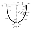
図6は、少なくとも1つの遠位端部613と少なくとも1つの近位端部616とを有する少なくとも1つの反射性又は半透過性の外側主面610、出力主面620、光注入領域623、光学容積626、及び光学容積626内に配設された切り替え可能な拡散体630、を含む照明構成要素600の断面図を示す。出力主面620は、少なくとも1つの反射性又は半透過性の外側主面610の少なくとも1つの遠位端部613に隣接する遠位面である。光注入領域623は、少なくとも1つの反射性又は半透過性の外側主面610の少なくとも1つの近位端部616に隣接している。図示の実施形態では、光注入領域623は入力面である。他の実施形態では、光注入領域容積は、レンズ構成要素、及び/又は、LEDなどの照明素子の一部を備えてもよい。切り替え可能な拡散体630は、その一部に光軸689に平行ではない面法線631を有し、この光軸は、照明構成要素600の対称軸であってもよく、切り替え可能な拡散体630が実質的に透明な状態にある場合に、平均光出力の方向であってもよい。出力主面620は、少なくとも1つの遠位端部613によって画定された平面にすることができる。例えば、出力主面620は、少なくとも1つの遠位端部613によって囲まれた平面領域であってもよい。同様に、光注入領域623は、少なくとも1つの近位端部616によって画定された平面であり得る入力面であってもよい。例えば、入力面は、少なくとも1つの近位端部616によって囲まれた平面領域であってもよい。
FIG. 6 illustrates at least one reflective or translucent outer
少なくとも1つの反射性又は半透過性の外側主面610は、ゾーン610a、610b、611a及び611bを含んでいる。各ゾーンは、照明構成要素600の切子面に対応することができる。各切子面は類似していてもよいし、異なる反射特性を有していてもよい。例えば、さまざまな切子面は、異なる反射率、透過率に対する反射率の異なる比率、異なる拡散反射度、反射率に対する異なる波長依存性、及び/又は反射率に対する異なる偏光依存性を提供することができる。切子面のサイズ、形状、分布、及び/又は、反射率若しくは透過率の特性を好適に選択することによって、切り替え可能な拡散体630を第1の状態から第2の状態に切り替えることにより、照明構成要素600からの光出力の角度分布及び/又はスペクトル分布及び/又は偏光分布を変更することができる。図示の実施形態では、照明構成要素600は、単一の切り替え可能な拡散体630を備える。他の実施形態では、2つ以上の切り替え可能な拡散体が含まれる。
At least one reflective or translucent outer
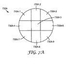
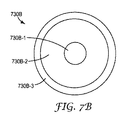
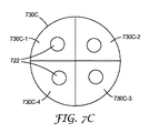
本明細書の切り替え可能な拡散体のいずれも、複数の独立してアドレス可能な領域を備えることができる。図7Aは、第1〜第9の独立してアドレス可能な領域730A−1〜730A−9を有する切り替え可能な拡散体730Aの上面図である。図7Bは、第1〜第3の独立してアドレス可能な領域730B−1〜730B−3を有する切り替え可能な拡散体730Bの上面図である。図7Cは、第1〜第4の独立してアドレス可能な領域730C−1〜730C−4を有する切り替え可能な拡散体730Cの上面図である。切り替え可能な拡散体730Cは、領域722において、この拡散体730C上に光を生成する4つのLEDを有する光源の上に配設される。それぞれ独立してアドレス可能な領域は1つのLEDに対応する。かかる配置によって、照明構成要素の光出力の有用な調整度が可能になる。LEDは、異なるスペクトルパワー分布関数を有することができる(例えば、LEDは異なる色のLEDであってもよい)か、あるいは、それらはすべて実質的に同じスペクトルパワー分布関数(例えば、すべてのLEDが白色であり得る同じ色を有してもよい)を有してもよい。LEDが異なる色のLEDである場合、異なる方向に異なる色の光出力を生成することができるさまざまな色の出力分布を制御するために、切り替え可能な拡散体730Cを使用することができる。これは、例えば、舞台照明などのさまざまな照明用途において、有用であり得る。4つのLED及び4つのアドレス可能な領域が図7Cに示されているが、任意の数のLED及び任意の数の独立してアドレス可能な領域を使用することができる。いくつかの実施形態では、切り替え可能な拡散体は、複数のLEDと位置合わせされてもよいが、LEDの数と、切り替え可能な拡散体の数又はアドレス可能な領域とに、1対1の対応があってもなくてもよい。例えば、切り替え可能な拡散体の単一の領域に対応する2つ以上のLEDがあってもよい。
Any of the switchable diffusers herein can include a plurality of independently addressable regions. FIG. 7A is a top view of a
セグメント化された層などの付加的な光学層は、別の所で更に説明するように、切り替え可能な拡散体に隣接して配設することができる。いくつかの実施形態では、セグメント化された層は、切り替え可能な拡散体に隣接して配設され、切り替え可能な拡散体の独立してアドレス可能な領域と位置合わせされている。セグメント化された層は、それぞれが光学効果を生成する複数のセグメントを有することができる。いくつかの実施形態では、切り替え可能な拡散体及びセグメント化された層は、LEDと位置合わせされて(例えば、図7Cのように)、各セグメントがその対応するLEDからの光出力を調整する。例えば、切り替え可能な拡散体の対応する領域が実質的に透明な状態にある場合に、セグメント化された層を通過した後の(切り替え可能な拡散体に平行な平面内の)第1のLEDの出力分布は、実質的に円形の分布を有することができ、切り替え可能な拡散体の対応する領域が実質的に透明な状態にある場合に、セグメント化された層を通過した後の(切り替え可能な拡散体に平行な平面内の)第2のLEDの出力分布は、楕円形の分布を有することができる。セグメント化された層は、層の異なるセグメントにおいて変化する複製されたパターン(例えば、マイクロ複製されたパターン)を有することができる。セグメント化された層に使用することができる好適な材料としては、例えば、表面レリーフホログラムを利用し得るLuminit、LLC(カリフォルニア州のTorrance)から入手可能な拡散体が挙げられる。切り替え可能な拡散体と、その独立してアドレス可能な領域がセグメント化された層と位置合わせされ、かつ、複数のLEDと位置合わせされているセグメント化された層と、の組み合わせにより、照明構成要素の光出力に対して、高度の調整が可能となる。 Additional optical layers, such as segmented layers, can be disposed adjacent to the switchable diffuser, as further described elsewhere. In some embodiments, the segmented layer is disposed adjacent to the switchable diffuser and is aligned with an independently addressable region of the switchable diffuser. A segmented layer can have a plurality of segments each producing an optical effect. In some embodiments, the switchable diffuser and segmented layer are aligned with an LED (eg, as in FIG. 7C), and each segment modulates the light output from its corresponding LED. . For example, the first LED (in a plane parallel to the switchable diffuser) after passing through the segmented layer if the corresponding region of the switchable diffuser is in a substantially transparent state The output distribution of the switch can have a substantially circular distribution and after switching through the segmented layer when the corresponding region of the switchable diffuser is in a substantially transparent state (switch The power distribution of the second LED (in a plane parallel to the possible diffuser) can have an elliptical distribution. A segmented layer can have a replicated pattern (eg, a microreplicated pattern) that varies in different segments of the layer. Suitable materials that can be used for the segmented layer include, for example, diffusers available from Luminit, LLC (Torrance, Calif.) That can utilize surface relief holograms. A combination of a switchable diffuser and a segmented layer whose independently addressable region is aligned with a segmented layer and aligned with a plurality of LEDs A high degree of adjustment is possible for the light output of the element.
9個、3個及び4個の独立してアドレス可能な領域が図7A〜図7Cに示されているが、任意の数の独立してアドレス可能な領域を使用することができる。例えば、切り替え可能な拡散体は、少なくとも10個、又は少なくとも100個の独立してアドレス可能な領域を含む、独立してアドレス可能な領域のx−yグリッドを有することができる。これは、x−yグリッド内の位置を通過する光注入領域からの光が特定の方向に反射されるような少なくとも1つの反射又は半透過の面の形状を有する実施形態に有用であり得る。独立してアドレス可能な領域のx−yグリッドを有することにより、照明構成要素からの角度、スペクトル、及び/又は偏光の出力分布に対して、高度の調整が可能になる。 Nine, three, and four independently addressable regions are shown in FIGS. 7A-7C, although any number of independently addressable regions can be used. For example, the switchable diffuser can have an xy grid of independently addressable areas, including at least 10, or at least 100 independently addressable areas. This can be useful for embodiments having the shape of at least one reflective or transflective surface such that light from a light injection region passing through a location in the xy grid is reflected in a particular direction. Having an independently addressable area xy grid allows a high degree of adjustment to the output distribution of angle, spectrum, and / or polarization from the illumination components.
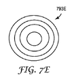
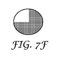
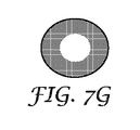
複数の独立してアドレス可能な領域を有する切り替え可能な拡散体を構成するために使用され得る電極は、図7D〜図7Eに示されている。電極793Dは、8個のくさび形の独立してアドレス可能な部分を含み、電極793Eは、同心円パターンで配置された4個の独立してアドレス可能な部分を備えている。電極793E又は793Dの各々は、例えば、パターン化されていない電極と組み合わせて、液晶ベースの切り替え可能な拡散体で使用してもよく、あるいは、パターン化された電極と組み合わせて使用してもよい。例えば、電極793E及び793Dは、図7F〜図7Hに示されるようなさまざまなヘイズパターンを生成するために、切り替え可能な拡散体内の対向する電極として使用してもよい。図7I又は図7Jに示すヘイズパターンを生成するために、別の電極の幾何学的形状を使用することができる。図7F〜図7Jは、任意の特定の時刻に発生させることができるヘイズパターンを例示する。切り替え可能な拡散体によって生成されるヘイズパターンは、ヘイズ状態のシーケンスを生成するように動的に変更することができる。例えば、切り替え可能な拡散体は、状態を順次変更して、所望の時間依存光出力を生成することができる。
The electrodes that can be used to construct a switchable diffuser having a plurality of independently addressable regions are shown in FIGS. 7D-7E.
いくつかの実施形態では、切り替え可能な拡散体は、別の所で説明するような双安定液晶を使用する。これによって、例えば、図7Jに示す蛇行したヘイズ状態が、「オフ」状態、即ち、電力が印加されていない場合に安定した状態であることが可能になる。これは、例えば、切り替え可能な拡散体がオフ状態にある場合に、会社ロゴなどのしるしを生成する照明構成要素において使用することができる。意図する用途に応じて、このしるしを生成するヘイズ状態は、低いヘイズ状態であって、そのしるしが僅かにしか生成されないか、あるいは、より強いコントラストを有するしるしを生成するより高いヘイズ状態であり得る。 In some embodiments, the switchable diffuser uses a bistable liquid crystal as described elsewhere. This allows, for example, the meandering haze state shown in FIG. 7J to be an “off” state, ie, a stable state when no power is applied. This can be used, for example, in lighting components that generate indicia such as company logos when the switchable diffuser is in the off state. Depending on the intended use, the haze state that produces this indicia is a low haze state that produces little indicia or a higher haze state that produces indicia with stronger contrast. obtain.
図7A〜図7Jに例示された切り替え可能な拡散体及び電極は、平面の幾何学的形状を有するものとして示されている。湾曲した幾何学的形状を含む他の幾何学的形状も可能であることを理解されたい。いくつかの実施形態では、切り替え可能な拡散体の断面が閉曲線となるように、切り替え可能な拡散体が湾曲している。例えば、切り替え可能な拡散体は、円筒形状を有してもよい。これは図7Kに示され、実質的に円筒形の形状を有し、かつ、さまざまな状態の領域を有する切り替え可能な拡散体730Kを示している。切り替え可能な拡散体は、水平又は垂直のストライプ状にパターン化することができ、あるいは、任意の他のパターン化を使用することができる。他の実施形態では、切り替え可能な拡散体は、例えば、ドーム形状などの複合曲線形状を有してもよい。
The switchable diffusers and electrodes illustrated in FIGS. 7A-7J are shown as having a planar geometry. It should be understood that other geometric shapes are possible, including curved geometric shapes. In some embodiments, the switchable diffuser is curved so that the cross-section of the switchable diffuser is a closed curve. For example, the switchable diffuser may have a cylindrical shape. This is shown in FIG. 7K and shows a
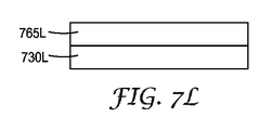
照明構成要素の光出力を調整するための切り替え可能な拡散体に加えて、追加の拡散体などの追加の光学素子を使用することが望ましい場合がある。いくつかの実施形態では、追加の光学素子(単数又は複数)を光学容積に含めることができ、切り替え可能な拡散体に隣接して配設することができる。これは図7Lに示されており、第1の切り替え可能な拡散体730Lに隣接して配設された追加の光学素子765Lが示され、図7Mには、第1の切り替え可能な拡散体730Mに隣接する追加の光学素子765M及び766Mが示されている。追加の素子は、光方向変換素子、スペクトル選択吸収器、偏光子(反射性又は吸収性)、又は静的拡散体などの静的(切り替え不可能な)素子であってもよい。これらの素子は、切り替え可能な拡散体の前(即ち、光注入領域に面して)及び/又は後(即ち、光注入領域と反対側)に配置することができる。例えば、第1の偏光子を切り替え可能な拡散体の前に配置し、第2の偏光子を切り替え可能な拡散体の後に配置することができる。追加の素子(単数又は複数)はまた、第2の切り替え可能な拡散体であってもよい。2つの切り替え可能な拡散体が使用される場合、第1及び第2の切り替え可能な拡散体は、それぞれ独立してアドレス可能な領域について、類似の又は異なる幾何学的形状を有することができる。2つの拡散体の拡散領域の重なりは、完全又は実質的に完全であるか、部分的であるか、又は全くないか、又は実質的にないとすることができる。2つの切り替え可能な拡散体は、位置合わせされていても、位置合わせされていなくてもよい。いくつかの実施形態では、第1の切り替え可能な拡散体730Lは、複数の独立してアドレス可能な領域を有し、付加的な光学素子765Lは、空間的な変化(例えば、分割されていてもよい)を有してかつ第1の切り替え可能な拡散体730Lと位置合わせされている、静的光学素子である。いくつかの実施形態では、追加の光学素子765M及び766Mのうちの1方は静的素子であり、他方は第2の切り替え可能な拡散体である。切り替え可能な拡散体の一方又は双方は、独立してアドレス可能な領域を有してもよく、当該静的素子は、空間的な変化を有してもよく、切り替え可能な拡散体の一方又は双方と位置合わせされてもよい。
In addition to the switchable diffuser to adjust the light output of the illumination component, it may be desirable to use additional optical elements such as additional diffusers. In some embodiments, additional optical element (s) can be included in the optical volume and can be disposed adjacent to the switchable diffuser. This is illustrated in FIG. 7L, where an additional
いくつかの実施形態では、第1の切り替え可能な拡散体(730L又は730M)は、例えば図7Cに示すように、個々のLEDと位置合わせされているが、他の実施形態では、第1の切り替え可能な拡散体は、LEDと位置合わせされていない。いくつかの実施形態では、第1の切り替え可能な拡散体(730L又は730M)は、例えば図7Cに示すように個々のLEDと位置合わせされ、少なくとも1つの追加の光学素子(例えば、追加の光学素子765L、765M又は766M)は、第1の切り替え可能な拡散体及び個々のLEDと位置合わせされた複数のセグメントを有する静的光学素子である。少なくとも1つの追加の光学素子は、別の所で更に説明するように、異なるセグメントに異なる微細構造を有するセグメント化された層であってもよい。
In some embodiments, the first switchable diffuser (730L or 730M) is aligned with individual LEDs, eg, as shown in FIG. 7C, while in other embodiments, the first switch The switchable diffuser is not aligned with the LED. In some embodiments, the first switchable diffuser (730L or 730M) is aligned with an individual LED, eg, as shown in FIG. 7C, and at least one additional optical element (eg, an additional optical element).
本明細書に記載された実施形態のいずれにおいても、追加の拡散体などの追加の光学素子は、光学容積内に少なくとも部分的に配設されてもよい。追加の拡散体は、切り替え可能な拡散体であってもよいし、切り替え不可能な拡散体であってもよい。いくつかの実施形態では、切り替え不可能な拡散体を、切り替え可能な拡散体に隣接して配設することができる。いくつかの実施形態では、切り替え不可能な拡散体などの付加的な光学素子を、切り替え可能な拡散体から離して、及び/又は切り替え可能な拡散体とは異なる向きで、光学容積内に配設してもよい。いくつかの実施形態では、複数の切り替え可能な拡散体が、少なくとも部分的に光学容積内に配設される。いくつかの実施形態では、追加の拡散体などの追加の光学素子を、光学容積の外側に配設することができる。 In any of the embodiments described herein, additional optical elements, such as additional diffusers, may be at least partially disposed within the optical volume. The additional diffuser may be a switchable diffuser or a non-switchable diffuser. In some embodiments, the non-switchable diffuser can be disposed adjacent to the switchable diffuser. In some embodiments, additional optical elements, such as non-switchable diffusers, are placed in the optical volume away from the switchable diffuser and / or in a different orientation than the switchable diffuser. You may set up. In some embodiments, a plurality of switchable diffusers is disposed at least partially within the optical volume. In some embodiments, additional optical elements such as additional diffusers can be disposed outside the optical volume.
図8は、少なくとも1つの遠位端部813と少なくとも1つの近位端部816とを有する少なくとも1つの反射性又は半透過性の外側主面810、出力主面820、光注入領域823、レンズ構成要素824、光源825、光学容積826、及び光学容積826内に配設された第1の切り替え可能な拡散体830、を含む照明構成要素800の断面図を示す。第1の切り替え可能な拡散体830は、第1主面832と第2主面834とを含む。照明構成要素800はまた、第1主面867及び対向する第2主面869を有する追加の光学素子865を含んでいる。出力主面820は、少なくとも1つの反射性又は半透過性の外側主面810の少なくとも1つの遠位端部813に隣接する遠位面である。図示の実施形態では、追加の光学素子865は、第2主面869が少なくとも1つの遠位端部813と同一平面にあり、第2主面869が出力主面820を形成するように配設される。他の実施形態では、追加の光学素子865は、出力主面820が第2主面869の上にあるように、少なくとも1つの遠位端部813の下に配置される。更に他の実施形態では、追加の拡散体は、少なくとも1つの遠位端部813を超えて延在してもよい。
FIG. 8 illustrates at least one reflective or translucent outer
追加の光学素子865は、光方向変換素子、スペクトル選択吸収器、偏光子、又は切り替え不可能な拡散体などの静的素子であってもよい。追加の光学素子865は、第2の切り替え可能な拡散体であってもよい。第1の切り替え可能な拡散体830は、複数の独立してアドレス可能な領域を含むことができる。追加の光学素子865は、複数の独立してアドレス可能な領域を含む第2の切り替え可能な拡散体であってもよい。追加の光学素子865は、空間的に変化し得るか、あるいは実質的に一様であり得るヘイズを有する切り替え不可能な拡散体であってもよい。第1の切り替え可能な拡散体830は、別の所で説明するように、少なくともいくつかの部分において、光学容積826の光軸に平行ではない面法線を有することができる。
The additional
光注入領域823は、少なくとも1つの反射性又は半透過性の外側主面810の少なくとも1つの近位端部816に隣接している。図示の実施形態では、光注入領域823は、レンズ構成要素824を含む容積である。光注入領域823は、入力面823aを含んでいる。いくつかの実施形態では、光注入領域823は、少なくとも1つの近位端部816に隣接する入力面823aであり、光源825及びレンズ構成要素824は、光学容積826の外側に配置されている。いくつかの実施形態では、光源825は、1つ以上の個別の照明素子(例えば、1つ以上のLED)を含み、光学容積826内に延在することができる。
少なくとも1つの反射性又は半透過性の外側主面810は、切り替え可能な拡散体830を挟んで光注入領域823の反対側の部分836を含む。部分836は、切り替え可能な拡散体830から少なくとも1つの遠位端部813まで延在している。いくつかの実施形態では、少なくとも1つの反射性又は半透過性の外側主面810は単一の面(図1A及び図1Bの面110に対応する)であり、いくつかの実施形態では、少なくとも1つの反射性又は半透過性の外側主面810は、2つの面(図2A及び図2Bの面210及び211に対応する)である。他の実施形態では、少なくとも1つの反射性又は半透過性の外側主面810は、3つ以上の面を含んでいる。部分836はまた、単一の面、2つの面、又は3つ以上の面であってもよい。少なくとも1つの反射性又は半透過性の外側主面810は、別の所で説明するように、空間的に変化する反射特性を有することができる。
The at least one reflective or translucent outer
照明構成要素800は、光注入領域823から出力主面820まで延在し、第1の切り替え可能な拡散体830を通る複数の経路を含む光路840を備えている。光路840は、第1の切り替え可能な拡散体830を通過し、追加の光学素子865の第1主面867から反射し、第1の切り替え可能な拡散体830を再び通過し、少なくとも1つの反射性又は半透過性の外側主面810から反射し、第1の切り替え可能な拡散体830を再び通過し、少なくとも1つの反射性又は半透過性の外側主面810から再び反射し、追加の光学素子865を通過し、出力主面820を通って出て行く。光路840は、出力主面820からのいかなる反射も含まず、光学容積826の外側の領域から光学容積826に入るいかなる部分又はセグメントも含んでいない。光路840は、第1の切り替え可能な拡散体830からのフレネル表面反射を含まない。
The
いくつかの実施形態では、照明構成要素800は、光注入領域823の光学素子、第1の切り替え可能な拡散体830、及び追加の光学素子865を除いて、実質的に中空である。いくつかの実施形態では、照明構成要素800は、光注入領域823の光学素子、第1の切り替え可能な拡散体830、及び追加の光学素子865を除いて、実質的に一体型である。
In some embodiments, the
図9は、少なくとも1つの遠位端部913と少なくとも1つの近位端部916とを有する少なくとも1つの反射性又は半透過性の外側主面910、出力主面920、光注入領域923、レンズ構成要素924、光源925、光学容積926、及び光学容積926内に配設された第1の切り替え可能な拡散体930、を含む照明構成要素900の断面図を示す。第1の切り替え可能な拡散体930は、第1主面932と第2主面934とを含む。照明構成要素900はまた、第1主面967及び対向する第2主面969を有する追加の光学素子965を含む。出力主面920は、少なくとも1つの反射性又は半透過性の外側主面910の少なくとも1つの遠位端部913に隣接する遠位面である。図示の実施形態では、追加の光学素子965は、第2主面969が少なくとも1つの遠位端部913と同一平面にあって、第2主面969が出力主面920を形成するように、配設される。他の実施形態では、追加の光学素子965は、出力主面920が第2主面969の上にあるように、少なくとも1つの遠位端部913の下に配置される。更に他の実施形態では、追加の拡散体は、少なくとも1つの遠位端部913を超えて延在してもよい。
FIG. 9 illustrates at least one reflective or translucent outer
追加の光学素子965は、光方向変換素子、スペクトル選択吸収器、偏光子、又は切り替え不可能な拡散体などの静的素子であってもよい。追加の光学素子965はまた、第2の切り替え可能な拡散体であってもよい。第1の切り替え可能な拡散体930は、複数の独立してアドレス可能な領域を含むことができる。追加の光学素子965は、複数の独立してアドレス可能な領域を含む第2の切り替え可能な拡散体であってもよい。追加の光学素子965は、空間的に変化し得るか、あるいは実質的に一様であり得るヘイズを有する切り替え不可能な拡散体であってもよい。
The additional
光注入領域923は、少なくとも1つの反射性又は半透過性の外側主面910の少なくとも1つの近位端部916に隣接している。図示の実施形態では、光注入領域923は、レンズ構成要素924を含む容積である。光注入領域923は、入力面923aを含んでいる。いくつかの実施形態では、光注入領域923は、少なくとも1つの近位端部916に隣接する入力面923aであり、光源及びレンズは、光学容積926の外側に配置されている。いくつかの実施形態では、光源925は、1つ以上の個別の照明素子(例えば、1つ以上のLED)を含み、光学容積926内に延在することができる。
いくつかの実施形態では、少なくとも1つの反射性又は半透過性の外側主面910は単一の面(図1A及び図1Bの面110に対応する)であり、いくつかの実施形態では、少なくとも1つの反射性又は半透過性の外側主面910は、2つの面(図2A及び図2Bの面210及び211に対応する)である。他の実施形態では、少なくとも1つの反射性又は半透過性の外側主面910は、3つ以上の面を含んでいる。他の実施形態では、少なくとも1つの反射性又は半透過性の外側主面910は、別の所で説明するように、空間的に変化する反射特性を有する。
In some embodiments, at least one reflective or translucent outer
照明構成要素900は、第1、第2及び第3のセグメント951、952及び953を含む光路950を備え、第1のセグメント951を含んで第2、第3及び第4のセグメント956、957及び958を含む光路955を備えている。光路950は、光注入領域923から始まり、出力主面920を通って延在する。光路950は、出力主面920からのいかなる反射も含まず、光学容積926の外側の領域から出力主面920を通って光学容積926に入るいかなる部分又はセグメントも含まず、第1の切り替え可能な拡散体930からの後方散乱も含まない。第1のセグメント951は、光注入領域923から開始し、第1の切り替え可能な拡散体930で終了する。光路950の場合、第1のセグメント951は、実質的に散乱することなく、第2のセグメント952として、切り替え可能な拡散体を通って透過する。これは、例えば、切り替え可能な拡散体が、第1のヘイズによって特徴付けることができる第1の状態にある場合に発生し得る。いくつかの実施形態では、第1の状態は実質的に透明な状態であり、第1のヘイズは実質的にゼロである。第2のセグメント952は、第3のセグメント953として少なくとも1つの反射性又は半透過性の外側主面910から反射し、追加の光学素子965を通過し、出力主面920を通って光学容積926を出て行く。
The
光路955の場合、第1のセグメント951は、それが第1の切り替え可能な拡散体930を透過するときに90度未満の散乱角θで散乱されて第2のセグメント956になり、少なくとも1つの反射性又は半透過性の外側主面910から、第3のセグメント957として反射される。第3のセグメントは、第1の切り替え可能な拡散体930を通過し、追加の光学素子965を通過するときに散乱して第4のセグメント958となる。第4のセグメント958は、出力主面920を通って光学容積926を出て行く。第1の切り替え可能な拡散体930による光路955の散乱は、例えば、切り替え可能な拡散体が、第1のヘイズとは異なる第2のヘイズに特徴付けられ得る第2の状態にある場合に、生じる可能性がある。例えば、第2のヘイズは、第1のヘイズよりも著しく大きくすることができる。光路955は、第1の切り替え可能な拡散体930からの後方散乱を含まず、第1の切り替え可能な拡散体930からのフレネル表面反射を含まないが、他の光路は、後方散乱又はフレネル表面反射を含んでもよい。光路955は、第1の切り替え可能な拡散体930を通る2つの経路を含む。
In the case of the
少なくとも1つの反射又は半透過の面は、直線状若しくは湾曲状であってもよく、あるいは、直線状の部分及び湾曲した部分を有してもよい。有用な形状には、円錐、放物線、又は不規則な形状が含まれ得る。いくつかの実施形態では、少なくとも1つの反射又は半透過の面が、光学容積の対向する境界を画定する。いくつかの実施形態では、切り替え可能な拡散体が、少なくとも1つの反射又は半透過の面に対して任意の向きで光学容積内に配設されてもよい。 At least one reflective or translucent surface may be straight or curved, or may have a straight portion and a curved portion. Useful shapes can include cones, parabolas, or irregular shapes. In some embodiments, at least one reflective or transflective surface defines opposing boundaries of the optical volume. In some embodiments, a switchable diffuser may be disposed in the optical volume in any orientation with respect to at least one reflective or transflective surface.
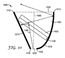
図10は、少なくとも1つの遠位端部1013及び少なくとも1つの近位端部1016を有する少なくとも1つの反射性又は半透過性の外側主面1010と、出力主面である遠位面1020と、照明構成要素1000に関する光注入領域である入力面1023と、を備えた照明構成要素1000を示す。少なくとも1つの反射又は半透過の面1010が、光学容積1026の対向する境界を画定する。光学容積1026は、入力面1023の面心から遠位面1020の面心まで延在する光軸1089を有する。第1の切り替え可能な拡散体1030は、光学容積1026内に配設される。照明構成要素1000はまた、第1の切り替え可能な拡散体1030に隣接して(この場合はじかに隣接する)配設された追加の光学素子1065を含む。図示の実施形態では、追加の光学素子1065は、第1の切り替え可能な拡散体1030の上にある。他の実施形態では、追加の光学素子1065は、第1の切り替え可能な拡散体1030の下に配設される。照明構成要素1000は、入力面1023から遠位面1020まで延在する光路1040を含んでいる。光路1040は、第1の切り替え可能な拡散体1030を通過する2つの経路を含む。追加の光学素子1065は、別の所で説明するように、静的又は切り替え可能な光学素子のいずれであってもよい。
FIG. 10 illustrates at least one reflective or translucent outer
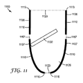
いくつかの実施形態では、少なくとも1つの反射性又は半透過性の外側主面は、単一の連続的な面(例えば、円錐形状)である。いくつかの実施形態では、少なくとも1つの反射性又は半透過性の外側主面は、2つの面の各々が単一の連続的な面(例えば、互いに分離された2つの平面)である2つの対向する面である。いくつかの実施形態では、少なくとも1つの反射又は半透過の面は、図11に示すように分離された部分を含む光学容積の対向する境界を画定する。 In some embodiments, the at least one reflective or translucent outer major surface is a single continuous surface (eg, a conical shape). In some embodiments, the at least one reflective or translucent outer major surface includes two surfaces, each of the two surfaces being a single continuous surface (eg, two planes separated from each other). It is an opposing surface. In some embodiments, the at least one reflective or transflective surface defines an opposing boundary of the optical volume that includes separated portions as shown in FIG.
図11は、少なくとも1つの遠位端部1113及び少なくとも1つの近位端部1116を有する少なくとも1つの反射性又は半透過性の外側主面1110と、出力主面である遠位面1120と、照明構成要素1100に関する光注入領域である入力面1123と、を備えた照明構成要素1100を示している。少なくとも1つの反射性又は半透過性の外側主面1110が、光学容積1126の対向する境界を画定する。切り替え可能な拡散体1130は、光学容積1126内に配設される。少なくとも1つの反射性又は半透過性の外側主面1110は、切り替え可能な拡散体1130を挟んで入力面1123の反対側の部分1136を含み、切り替え可能な拡散体1130と入力面1123との間の部分1137を含んでいる。部分1136は、(例えば、照明構成要素1100が図2Bのものと同様の上面図を有する場合)複数のセグメントを含むことができ、あるいは、単一のセグメントを含むことができる(例えば、照明構成要素1100が図1Bのものと同様の上面図を有する場合)。同様に、部分1037は、(例えば、照明構成要素1100が図2Bのものと同様の上面図を有する場合)複数のセグメントを含むことができ、あるいは、単一のセグメントを含むことができる(例えば、照明構成要素1100が図1Bのものと同様の上面図を有する場合)。光学容積1126の境界の1つ以上のセグメント1167は、(例えば、照明構成要素1100が図2Bのものと同様の上面図を有する場合)平面のセグメントとすることができ、あるいは、円錐形のセグメントとすることができる(例えば、照明構成要素1100が図2Bのものと同様の上面図を有する場合)。部分1136及び部分1137などの別個の部分を使用することは、照明構成要素1100を構成するのに有用であり得る。最終的なアセンブリでは、部分1136及び1137が接触又はほぼ接触するように、セグメント1167は図11に示すよりも小さくすることができる。いくつかの実施形態では、切り替え可能な拡散体1130は、少なくともそのいくつかの部分において、光学容積1126の光軸に平行ではない面法線を有する。
FIG. 11 illustrates at least one reflective or translucent outer
いくつかの実施形態では、反射性又は半透過性の外側主面1110は、一様又は実質的に一様な反射率及び/又は透過率を有することができ、他の実施形態では、少なくとも1つの反射性又は半透過性の外側主面1110は、面に沿って変化する反射率及び/又は透過率の特性を有することができる。この変化は、実質的に連続的とすることができるか、あるいは、別個のゾーンが異なる反射率及び/又は透過率の特性を有することができる。反射性又は半透過性の外側主面1110の形状及び/又は反射率及び/又は透過率の特性は、切り替え可能な拡散体を第1の状態から第2の状態に切り替えることによって、照明構成要素1100からの光出力の角度分布及び/又はスペクトル分布及び/又は偏光分布を変化させるように、選択することができる。切り替え可能な拡散体1130は、複数の独立してアドレス可能な領域を有することができる。切り替え可能な拡散体1130の複数の独立してアドレス可能な領域は、別の所で説明するように、反射性又は半透過性の外側主面1110のゾーンに対応することができる。
In some embodiments, the reflective or translucent outer
図12Aは、少なくとも1つの遠位端部1213及び少なくとも1つの近位端部1216を有する少なくとも1つの反射性又は半透過性の外側主面1210と、出力主面である遠位面1220と、光注入領域1223と、を備えた照明構成要素1200の断面図を示す。光注入領域1223は、入力面1223a及びレンズ構成要素1224を含む。光源1225は、光を入力面1223aに入射するように配設される。いくつかの実施形態では、光源1225は、1つ以上の個別の照明素子(例えば、1つ以上のLED)を含み、光学容積1226内に延在することができる。少なくとも1つの反射性又は半透過性の外側主面1210が、光学容積1226の対向する境界を画定する。切り替え可能な拡散体1230は、光学容積1226内に配置され、内側主面1232及び外側主面1234を含んでいる。遠位面1220は、外側主面1234の一部を含む。
FIG. 12A illustrates at least one reflective or translucent outer
照明構成要素1200は、光注入領域1223から遠位面1220まで延在する光路1240を含んでいる。光路1240は、切り替え可能な拡散体1230を通る3つの経路を含む。
The
少なくとも1つの反射性又は半透過性の外側主面1210は、切り替え可能な拡散体1230を挟んで入力面1223aの反対側の部分1236を含み、切り替え可能な拡散体1230と入力面1223aとの間の部分1237を含んでいる。部分1236は部分1237から物理的に離れている。部分1237は、(例えば、照明構成要素1200が図12Bの照明構成要素1200Bのものに類似するくさび形状を有する場合)複数のセグメントを含むことができるか、あるいは、単一のセグメントを含むことができる(例えば、照明構成要素1200が、図12Cの照明構成要素1200Cのものと類似する円筒形又は軸対称の形状を有する場合)。
At least one reflective or semi-transmissive outer
いくつかの実施形態では、遠位面1220は、部分1236の各側に別個のセグメントを含む。これは、少なくとも1つの反射性又は半透過性の外側主面1210Bの部分1236Bの各側に別個のセグメント(この場合、実質的に矩形である)を含む遠位面1220Bを有する照明構成要素1200Bの上面図を示す図12Bに表されている。照明構成要素1200Bは、図12Aのそれに対応する断面図を有する。照明構成要素1200Bは、光注入領域から遠位面1220Bまで延在する第1の面(図12Aの部分1237の左側に対応する)と、光注入領域から遠位面1220Bまで延在する対向する第2の面(図12Aの部分1237の右側に対応する)と、光注入領域の反対側の遠位面1220Bに隣接して配設された部分1236Bに対応する第3の面と、を含む少なくとも1つの反射性又は半透過性の外側主面1210Bを有するものとして説明することができる。
In some embodiments, the
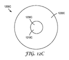
いくつかの実施形態では、遠位面1220は、部分1236を囲む単一セグメントを含んでいる。これは、少なくとも1つの反射性又は半透過性の外側主面1210Cの部分1236Cを囲む実質的に環状である遠位面1220Cを有する照明構成要素1200Cの上面図を示す図12Cに表されている。照明構成要素1200Cは、図12Aのそれに対応する断面図を有する。照明構成要素1200Cは、光注入領域から遠位面1220Cまで延在する第1の軸対称面(図12Aの部分1237に対応する)を含む少なくとも1つの反射性又は半透過性の外側主面1210Cを有するものとして説明することができる。他の実施形態では、部分1237は、光注入領域から遠位面1220Cまで延在する軸対称ではなく非対称の面を形成する。
In some embodiments, the
少なくとも1つの反射性又は半透過性の外側主面1210は、別の所で説明するように、異なる反射特性を有するゾーンを備えることができる。例えば、部分1236及び1237は、異なる反射性を有してもよいし、あるいは、異なる表面散乱を提供してもよい。切り替え可能な拡散体1230は、複数の独立してアドレス可能な領域を含むことができる。切り替え可能な拡散体1230の複数の独立してアドレス可能な領域は、別の所で説明するように、反射性又は半透過性の外側主面1210のゾーンに対応することができる。
The at least one reflective or translucent outer
本明細書で使用されるとき、反射又は半透過の面の形状とは、面の全体的な形状を指し、面の全体的な曲率半径と比較して小さい反射又は半透過の面に包含される形体のことを指さない。かかる形体は、面の全体的な形状の曲率半径の10パーセント未満、又は5パーセント未満、又は2パーセント未満の高さ又は中心間間隔を有するならば、小さいとみなすことができる。例えば、図13Aの構造化表面1312Aは、形体サイズhが曲率半径Rと比較して小さいので、図13Bの面1312Bの全体的な形状を有するものとして説明することができる。本明細書の照明構成要素の反射又は半透過の面は、構造化表面1312Aに対応する形状を有することができる。これは、図13Cの照明構成要素1300に示されている。照明構成要素1300は、構造化表面1312Aに対応する部分を含む少なくとも1つの反射性又は半透過性の外側主面1310を備えている。照明構成要素1300はまた、遠位面1320、入力面1323、及び切り替え可能な拡散体1330を含んでいる。少なくとも1つの反射性又は半透過性の外側主面1310は、入力面1323から、出力主面であり得る遠位面1320まで、実質的に単調に広がると言うことができる。いくつかの実施形態では、少なくとも1つの反射性又は半透過性の外側主面1312Cは、光注入領域(入力面1323を含み得る)から遠位面1320まで、実質的に収束するか又は広がるがその両方ではない光学容積1326の対向する境界を画定する。
As used herein, the shape of a reflective or translucent surface refers to the overall shape of the surface and is encompassed by a reflective or translucent surface that is small compared to the overall radius of curvature of the surface. Do not refer to any form. Such a feature can be considered small if it has a height or center-to-center spacing of less than 10 percent, or less than 5 percent, or less than 2 percent of the radius of curvature of the overall shape of the surface. For example, the
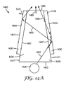
図14Aは、少なくとも1つの反射性又は半透過性の外側主面1410、任意の1つ以上の追加の面1411、出力主面とすることができる遠位面1420、照明構成要素1400の光注入領域である入力面1423、光源1425、光学容積1426、透明な光学物体1429、少なくとも1つの外側主面1434を有する少なくとも1つの拡散体1430、第1のセグメント1451を含む光路1450、及び第1のセグメント1451をまた含む光路1455、を含む照明構成要素1400の断面図を示している。照明構成要素1400は、透明な光学物体1429の少なくとも1つの傾斜主面1497に少なくとも1つの拡散体1430を取り付けることによって製作することができる。
FIG. 14A illustrates at least one reflective or translucent outer
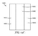
透明な光学物体1429は、実質的に円筒対称又は軸対称であってもよく、その場合、少なくとも1つの拡散体1430は、透明な光学物体1429の周りを包み込むか、実質的に包み込む単一の拡散体であってもよい。少なくとも1つの反射性又は半透過性の外側主面1410は、透明な光学物体1429の断面を取り囲む連続的な面を含むことができ、少なくとも1つの拡散体1430は、連続的な面を実質的に覆う切り替え可能な拡散体を含むことができる。これは、照明構成要素1400に対応して、かつ、遠位面1420B、透明な光学物体1429B、及び外側主面1434Bを有する拡散体1430B、を含む、照明構成要素1400Bの上面図を表す図14Bに示されている。照明構成要素1400Bは、照明構成要素1400のものと実質的に等しい断面図を有する。あるいは、透明な光学物体1429はくさび形物体とすることができ、少なくとも1つの拡散体1430は、透明な光学物体1429を挟んで両側に2つの別個の拡散体を含むことができる。これは、図14Cに示されており、この図には、照明構成要素1400に対応して、かつ、遠位面1420C、透明な光学物体1429C、及び少なくとも1つの外側主面を有する少なくとも1つの拡散体、を含む、照明構成要素1400Cの上面図が表されている。少なくとも1つの拡散体は、それぞれ、第1及び第2の外側主面1434C及び1435Cを有する第1及び第2の拡散体1430C及び1431Cを備えている。照明構成要素1400Cは、照明構成要素1400と実質的に等しい断面図を有する。
The transparent
照明構成要素1400は、少なくとも1つの拡散体1430の少なくとも1つの外面を含む少なくとも1つの反射性又は半透過性の外側主面1410を含んでいる。照明構成要素1400の幾何学的形状及び少なくとも1つの拡散体1430の屈折率は、入力面1423に注入された光の少なくとも一部が全反射(TIR)によって少なくとも1つの拡散体1430の外面から反射されるように、選択される。照明構成要素1400は、少なくとも1つの拡散体1430によって覆われていない透明な光学物体1429の側面(単数又は複数)の一部であり得る任意の1つ以上の追加の面1411を含んでもよい。いくつかの場合には、任意の1つ以上の付加的な面1411は、反射性又は半透過性の主面である。かかる場合、1つ以上の反射性又は半透過性の外側主面1410は、任意の1つ以上の追加の面1411を含むことができる。いくつかの実施形態では、少なくとも1つの拡散体1430は、入力面1423及び遠位面1420及びあり得る副次的な面、以外の透明な光学物体1429の表面を覆うか、又は実質的に覆うものである。かかる実施形態では、任意の1つ以上の追加の面1411は存在しなくてもよいか、又は、副次的な面だけを含んでもよい。
The
少なくとも1つの拡散体1430は、照明構成要素1400Bにおけるように、単一の切り替え可能な拡散体であり得る少なくとも1つの切り替え可能な拡散体を含むか、あるいは、第1の切り替え可能な拡散体、及び、切り替え可能若しくは切り替え不可能な第2の拡散体とすることができる。例えば、第1の拡散体1430Cは、第1の切り替え可能な拡散体であってもよく、第2の拡散体1431Cは、第2の切り替え可能な拡散体であってもよいし、あるいは、切り替え不可能な拡散体であってもよい。少なくとも1つの拡散体1430は、複数の独立して切り替え可能な領域を含むことができる。少なくとも1つの切り替え可能な拡散体が、実質的に透明な状態などの空間的に一様な状態にある場合、少なくとも1つの拡散体1430は、光学容積1426の光軸に平行ではなくて、及び/又は平均光出力1489の方向に平行ではない、面法線1431を有することができる。少なくとも1つの切り替え可能な拡散体が、実質的に透明な状態などの空間的に一様な状態にある場合の平均光出力1489の方向は、光学容積1426の光軸に一致してもよい。
The at least one
照明構成要素1400は、入力面1423から遠位面1420まで延在する光路1450を含む。光路1450は、光源1425と透明な光学物体1429の少なくとも1つの傾斜主面1497との間の第1のセグメント1451を含んでいる。光路1450は、遠位面1420から出る前に、少なくとも1つの反射性又は半透過性の外側主面1410から2回反射される。光路1450は、実質的に散乱することなく、少なくとも1つの拡散体1430を通過する4つの経路(各側に2つ)を作成する。これは、少なくとも1つの拡散体1430が、実質的に透明な状態であり得る第1の状態にある場合に、発生する可能性がある。光路1455は、少なくとも1つの拡散体1430がヘイズ状態であり得る第2の状態にある場合に、発生する可能性がある。光路1455は、第1のセグメント1451を含み、少なくとも1つの拡散体1430によって散乱され、少なくとも1つの反射性又は半透過性の外側主面1410から反射し、少なくとも1つの拡散体1430によって再び散乱され、遠位面1420を通って出て行く。光路1455は、光学容積1426を出る前に、少なくとも1つの反射性又は半透過性の外側主面1410からの1回の反射だけを含み、光路1450は、光学容積1426を出る前に少なくとも1つの反射性又は半透過性の外側主面1410からの2回の反射を含んでいる。光路1450及び1455は、光源1425から開始し、入力面1423を通過し、遠位面1420を通って延在する。光路1450及び1455は、遠位面1420からのいかなる反射も含まず、光学容積1426の外側の領域から外側主面420を通って光学容積426に入るいかなる部分又はセグメントも含まない。
The
他の光路は、少なくとも1つの外側主面1434を通って、又は任意の1つ以上の追加の面1411を通って、光学容積1426を出てもよい。遠位面1420を通って光学容積1426を出る光の割合は、少なくとも1つの拡散体1430の状態を変更することによって、変更することができる。照明構成要素1400からの光出力は、少なくとも1つの拡散体1430が第1の状態にある場合には、第1の出力分布を有することができ、少なくとも1つの拡散体1430が第2の状態にある場合には、第1の出力分布とは異なる第2の出力分布を有することができる。
Other optical paths may exit the
少なくとも1つの反射性又は半透過性の外側主面1410は、空間的に変化する反射及び/又は透過の特性を有することができる。かかる特性は、異なる可視光の全体的な反射率及び/又は透過率、及び/又は異なる波長依存性の反射率及び/又は透過率、及び/又は異なる偏光依存性の反射率及び/又は透過率を含み得る。異なる反射及び/又は透過の特性は、別の所で説明するようなさまざまなMOFフィルムを使用して、実現することができる。例えば、可変の有孔密度を有する有孔反射体フィルム又は有孔反射型偏光子が、少なくとも1つの拡散体1430の少なくとも1つの外側主面1434に隣接して配置されてもよい。このフィルム(単数又は複数)は、光学的に透明な接着剤を使用して取り付けてもよく、又は空気間隙が少なくとも1つの外側主面1434からフィルムを分離してもよい。追加の反射層又は半透過層が外側主面に隣接して配置される実施形態は、別の所で更に説明する。
The at least one reflective or translucent outer
透明な光学物体1429は、実質的に一体型な光学的に透明な構成要素であってもよく、光学容積1426は、少なくとも1つの拡散体1430を除いて、実質的に一体型であってもよい。透明な光学物体1429は、入力面1423から遠位面1420まで、実質的に収束するか又は広がるがその両方ではない少なくとも1つの傾斜主面1497を備えることができる。
The transparent
図15は、少なくとも1つの反射性又は半透過性の外側主面1510、出力主面であり得る遠位面1520、照明構成要素1500の光注入領域である入力面1523、光源1525、光学容積1526、少なくとも1つの透明な光学物体1529、切り替え可能な拡散体1530、第1のセグメント1551を有する光路1550、及び、第1のセグメント1551もまた含む光路1555、を含む照明構成要素1500の断面図を示す。いくつかの実施形態では、照明構成要素1500は、照明構成要素1400Bに類似した実質的に円筒対称又は軸対称の形状を有することができる。かかる実施形態では、切り替え可能な拡散体1530は、少なくとも1つの透明な光学物体1529(単一の透明な光学的固体であり得る)のくり抜かれた領域内に配設されてもよい。いくつかの実施形態では、照明構成要素1500は、照明構成要素1400Cに類似した実質的にくさび形の形状を有することができる。これらの実施形態では、少なくとも1つの透明な光学物体1529は、切り替え可能な拡散体1530の対向する表面に取り付けられた2つの別個のくさびを含むことができる。少なくとも1つの反射性又は半透過性の外側主面1510は、少なくとも1つの透明な光学物体1529の少なくとも1つの主面を含む。少なくとも1つの透明な光学物体1529は、実質的に一体型であってもよく、あるいは、複数の実質的に一体型な構成要素を含んでもよい。光学容積1526は、切り替え可能な拡散体1530を除いて、実質的に一体型にすることができる。
FIG. 15 illustrates at least one reflective or translucent outer
切り替え可能な拡散体1530は、複数の独立してアドレス可能な領域を含むことができる。別の所で説明するように、これによって、光出力分布の調整度を改善することができる。切り替え可能な拡散体1530は、実質的に透明な状態にある場合の平均光出力の方向に平行ではない面法線を有することができる。切り替え可能な拡散体1530は、実質的に透明な状態にある場合、光学容積1526の光軸に直交又は実質的に直交する、及び/若しくは、平均光出力の方向に直交する、面法線を有することができる。
The
照明構成要素1500は、第1のセグメント1551を含んで、かつ、遠位面1520を通って光学容積1526を出る前に、少なくとも1つの反射性又は半透過性の外側主面1510からのTIRを2回受ける、光路1550を含んでいる。第1のセグメント1551は、光源1525から、少なくとも1つの反射性又は半透過性の外側主面1510からの第1の反射まで延在する。光路1550は、実質的に散乱することなく、切り替え可能な拡散体1530を透過し、切り替え可能な拡散体1530が低ヘイズ状態又は実質的に透明な状態であり得る第1の状態にある場合に、発生し得る。光路1555は、第1のセグメント1551を含み、少なくとも1つの反射性又は半透過性の外側主面1510からの反射を含むが、切り替え可能な拡散器1530を透過するときに散乱され、その後、少なくとも1つの反射性又は半透過性の外側主面1510にTIRの臨界角未満の入射角で入射し、光路1550は、少なくとも1つの反射性又は半透過性の外側主面1510を通って光学容積1526を出て行く。光路1555は、少なくとも1つの反射性又は半透過性の外側主面1510からの1回の反射だけを含み、光路1550は2回のかかる反射を含んでいる。
遠位面1520を通って光学容積1526を出る光の割合は、切り替え可能な拡散体1530の状態を変更することによって、変更することができる。照明構成要素1500からの光出力は、切り替え可能な拡散体1530が第1の状態にある場合に、第1の出力分布を有することができ、切り替え可能な拡散体1530が第2の状態にある場合には、第1の出力分布とは異なる第2の出力分布を有することができる。切り替え可能な拡散体が実質的に透明な状態である場合、遠位面を通って光学容積を出る光の割合は、少なくとも1つの反射性又は半透過性の外側主面1510のテーパを減少させることによって増加させることができる。少なくとも1つの反射性又は半透過性の外側主面1510は、光注入領域1523から遠位面1520に実質的に収束する光学容積1526の対向する境界を画定することができる。
The percentage of light exiting the
いくつかの実施形態では、光源1525と光学容積1526との間に追加の切り替え可能な拡散体が配設される。追加の切り替え可能な拡散体が実質的に透明な状態にある場合、光源1525からの光は、光の実質的な部分が光学容積を透過し、遠位面1520を通って光学容積1526を出て行くような角度分布で光学容積1526に入る。この光の少なくとも一部は、少なくとも1つの反射性又は半透過性の外側主面1510から、TIRによって、遠位面1520に向けられてもよい。追加の切り替え可能な拡散体がヘイズ状態にある場合、光源1525からの光は、光注入領域1523に到達する前に拡散される。この拡散された光の第1の部分は、光学容積1526に入らないように、追加の切り替え可能な拡散体によって散乱させることができる。拡散された光の第2の部分は、少なくとも1つの反射性又は半透過性の外側主面1510からTIRを生じないような角度で光学容積1526に入ることができる。拡散された光の第3の部分は、光学容積1526を伝搬して遠位面1520を通って出て行くことができるような角度で、光学容積1526に入ることができる。したがって、追加の切り替え可能な拡散体によって、光出力の分布の追加の制御度が提供される。別の実施形態では、切り替え可能な拡散体1530は光学容積1526の中に含まれず、光源1525と光学容積1526との間に配設された切り替え可能な拡散体によって光出力の分布が調整される。
In some embodiments, an additional switchable diffuser is disposed between the
図16は、少なくとも1つの反射性又は半透過性の外側主面1610、出力主面1620、照明構成要素1600の光注入領域である入力面1623、光源1625、光学容積1626、少なくとも1つの透明な光学物体1629、切り替え可能な拡散体1630、第1のセグメント1651を有する光路1650、第1のセグメント1651もまた含む光路1655a、第1のセグメント1651もまた含む光路1655b、を備えた照明構成要素1600の断面図を示す。いくつかの実施形態では、照明構成要素1600は、照明構成要素1400Bに類似した実質的に円筒形又は軸対称の形状を有することができる。これらの実施形態では、切り替え可能な拡散体1630は、少なくとも1つの透明な光学物体1629(単一の透明な光学的固体であり得る)のくり抜かれた領域内に配設されてもよい。いくつかの実施形態では、照明構成要素1600は、照明構成要素1400Cに類似した実質的に矩形(又は直方体)の形状を有することができる。これらの実施形態では、少なくとも1つの透明な光学物体1629は、切り替え可能な拡散体1630の対向する面に取り付けられた2つの別個のくさびを含むことができる。少なくとも1つの反射性又は半透過性の外側主面1610は、少なくとも1つの透明な光学物体1629の少なくとも1つの主面を含む。
FIG. 16 illustrates at least one reflective or translucent outer
光路1650は、光源1625から開始し、光注入領域(入力面1623)を通って光を注入するように配設され、出力主面1620を通って延在する。光路1650は、少なくとも1つの反射性又は半透過性の外側主面1610からの2回の反射を含み、切り替え可能な拡散体1630を通る2つの経路を含んでいる。光路1650は、実質的に散乱することなく、切り替え可能な拡散体1630を透過する。これは、切り替え可能な拡散体が、実質的に透明な状態であり得る第1の状態にある(即ち、第1の状態は実質的にゼロである第1のヘイズを有することができる)場合に、生じる可能性がある。第1のセグメント1651は、光源1625から開始し、少なくとも1つの反射性又は半透過性の外側主面1610からの光路1650の第1の反射で終了する。
The
光路1655aは、第1のセグメント1651を含むが、切り替え可能な拡散体1630を通過するときに散乱され、少なくとも1つの反射性又は半透過性の外側主面1610から更に2回反射し、次いで出力主面1620を通って光学容積1626を出て行く。光路1655aは、切り替え可能な拡散体が、第1のヘイズよりも高い第2のヘイズを有し得る第2の状態にある場合に、生じる可能性がある。光路1655bは、第1のセグメント1651を含むが、切り替え可能な拡散体1630を通過するときに散乱され、少なくとも1つの反射性又は半透過性の外側主面1610から更に反射することなく、出力主面1620を通って光学容積1626を出て行く。光路1655bは、切り替え可能な拡散体が、第2のヘイズよりも高い第3のヘイズを有し得る第3の状態にある場合に、生じる可能性がある。
The optical path 1655a includes a
光路1650、1655a及び1655bは、光源1625から開始し、入力面1623を通過し、出力主面1620を通って延在する。光路1650、1655a及び1655bは、出力主面1620からのいかなる反射も含まず、光学容積1626の外側の領域から出力主面1620を通って光学容積1626に入るいかなる部分又はセグメントも含まず、切り替え可能な拡散体1630からのフレネル表面反射を含まず、切り替え可能な拡散体1630からの後方散乱を含まない。
The
光路1650は、少なくとも1つの反射性又は半透過性の外側主面1610からの第1の数(2)の反射を含み、光路1655aは、少なくとも1つの反射性又は半透過性の外側主面1610からの第2の数(3)の反射を含み、光路1655bは、少なくとも1つの反射性又は半透過性の外側主面1610からの第3の数(1)の反射を含む。
The
切り替え可能な拡散体1630は、複数の独立してアドレス可能な領域を含むことができる。別の所で説明するように、これによって、光出力分布の調整度を改善することができる。第1の切り替え可能な拡散体1630は、光学容積1626の光軸に平行ではない面法線を有することができる。切り替え可能な拡散体1630は、光学容積1626の光軸に直交するか又は実質的に直交する面法線を有することができる。光学容積1626の光軸は、切り替え可能な拡散体1630が実質的に透明な状態にある場合の平均光出力の方向に平行であってもよい。
The
いくつかの実施形態では、切り替え可能な拡散体1630は、光学容積1626の全長にわたって延在していなくてもよく、及び/又は光学容積1626の実質的に中心に位置しなくてもよい。かかる実施形態の一例を図17に示す。
In some embodiments, the
図17は、少なくとも1つの反射性又は半透過性の外側主面1710、出力主面1720、照明構成要素1700の光注入領域である入力面1723、光源1725、光学容積1726、透明な光学物体1729、切り替え可能な拡散体1730、第1のセグメント1751を有する光路1750、及び、第1のセグメント1751もまた含む光路1755、を含む照明構成要素1700の断面図を示す。いくつかの実施形態では、照明構成要素1700は、照明構成要素1400Bに類似した実質的に円筒形又は軸対称の形状を有することができる。いくつかの実施形態では、照明構成要素1700は、照明構成要素1400Cに類似した実質的に直方体の形状を有することができる。切り替え可能な拡散体1730は、単一の光学的固体であり得る透明な光学物体1729のくり抜かれた領域内に配設されてもよく、又は光学的固体の屈折率に一致した1つ以上の光学的に透明な接着剤によって、一緒に切り替え可能な拡散体1730に取り付けられる複数の光学固体を含んでもよい。
FIG. 17 shows at least one reflective or translucent outer
光路1750は、光源1725から、少なくとも1つの反射性又は半透過性の外側主面1710まで延在する第1のセグメント1751を含んでいる。光路1750は、少なくとも1つの反射性又は半透過性の外側主面1710から反射し、切り替え可能な拡散体1730を通過し、切り替え可能な拡散体1730の面から反射し、切り替え可能な拡散体を通って戻り、出力主面1720を通って照明構成要素1700を出て行く。光路1750は、切り替え可能な拡散体1730を通る2つの経路を含んでいる。光路1750は、切り替え可能な拡散体1730を通過するときに実質的に散乱されない。これは、切り替え可能な拡散体が、実質的に透明な状態であり得る第1の状態にある場合に、生じる可能性がある。光路1755は、第1のセグメント1751もまた含み、少なくとも1つの反射性又は半透過性の外側主面1710から切り替え可能な拡散体1730の方にまた反射される。光路1755は、切り替え可能な拡散体1730を通過するときに散乱し、少なくとも1つの反射性又は半透過性の外側主面1710からの第2の反射を含み、再び散乱する切り替え可能な拡散体1730を通る第2の経路を含み、続いて、光路1755は、出力主面1720を通って照明構成要素1700を出て行く。光路1750及び1755は、出力主面1720からのいかなる反射も含まず、光学容積1726の外側の領域から出力主面1720を通って光学容積1726に入るいかなる部分又はセグメントも含まず、切り替え可能な拡散体1730からの後方散乱を含まない。
The
切り替え可能な拡散体1730は、複数の独立してアドレス可能な領域を含むことができる。別の所で説明するように、これによって、光出力分布の調整度を改善することができる。切り替え可能な拡散体1730は、光学容積1726の光軸に平行ではない面法線を有することができる。切り替え可能な拡散体1730は、光学容積1726の光軸に直交するか、あるいは実質的に直交するか、あるいは傾斜した角度を有する、面法線を備えることができる。光学容積1726の光軸は、切り替え可能な拡散体が実質的に透明な状態にある場合の平均光出力の方向に平行であってもよい。
The
図14A〜図17に示す実施形態のいずれも、光学容積の少なくとも1つの反射性又は半透過性の外側主面に隣接する追加の反射層又は半透過層を更に含むことができる。付加反射層又は半透過層を有さない照明構成要素は、第1の光学容積を有すると理解され、追加の反射層又は半透過層の追加は、第1の光学容積を含み、かつ、第1の光学容積と追加の反射層又は半透過層の外面との間に追加の容積を含む、第2の光学容積を画定すると理解される。かかる実施形態の一例を図18に示す。 Any of the embodiments shown in FIGS. 14A-17 may further include an additional reflective or semi-transmissive layer adjacent to at least one reflective or semi-transmissive outer major surface of the optical volume. An illumination component that does not have an additional reflective or transflective layer is understood to have a first optical volume, the addition of an additional reflective or transflective layer includes the first optical volume, and It is understood that a second optical volume is defined that includes an additional volume between one optical volume and the outer surface of the additional reflective or transflective layer. An example of such an embodiment is shown in FIG.
図18は、少なくとも1つの反射性又は半透過性の外側主面1810a、出力主面1820、光注入領域1823、レンズ1824、光源1825、光学容積1826a、透明な光学物体1829、切り替え可能な拡散体1830、少なくとも1つの追加の反射性又は半透過性の層1810b、光学容積1826aを含み、かつ、少なくとも1つの反射性又は半透過性の外側主面1810aと少なくとも1つの追加の反射性又は半透過性の層1810bとの間の空間を含む、光学容積1826b、を含む照明構成要素1800の断面図を示す。この空間は空気間隙であってもよいし、あるいは、光学的に透明な接着剤で充填されていてもよい。照明構成要素1800は、任意の幾何学的形状を有することができ、別の所で説明するように、実質的に円筒形対称若しくは軸対称の幾何学的形状を有することができるか、あるいは、別の所で説明するように、実質的にくさびの幾何学的形状若しくは実質的に直方体の幾何学的形状を有することができる。切り替え可能な拡散体1830は、光学容積1826aの中心若しくはその近くに配設されてもよいし、あるいは、中心からずれていてもよい。少なくとも1つの追加の反射性又は半透過性の層1810bは、TIRの臨界角未満の入射角で少なくとも1つの反射性又は半透過性の外側主面1810aに入射する光が、少なくとも1つの反射性又は半透過性の外側主面1810aを透過し、続いて、少なくとも1つの追加の反射性又は半透過性の層1810bから反射されて光学容積1826aに戻る。
FIG. 18 shows at least one reflective or translucent outer
光路1840は、光注入領域1823から開始し、出力主面1820を通って照明構成要素1800を出て行く。光路1840は、切り替え可能な拡散体1830を通る3つの経路を含んでいる。
The
切り替え可能な拡散体1830は、複数の独立してアドレス可能な領域を含むことができる。少なくとも1つの追加の反射性又は半透過性の層1810bは、別の所で説明するように、空間的に変化する反射及び/又は透過の特性を有することができる。異なる反射及び/又は透過の特性は、例えば、別の所で説明するようなさまざまなMOFフィルムを使用して実現することができる。少なくとも1つの追加の反射性又は半透過性の層1810bは、別の所で説明するように、異なる反射又は透過の特性を有する複数のゾーンを備えることができる。このゾーンは、切り替え可能な拡散体1830の独立してアドレス可能な領域に対応することができる。少なくとも1つの追加の反射性又は半透過性の層1810bの反射及び/又は透過の特性を好適に選択することによって、照明構成要素1800の光出力は、切り替え可能な拡散体1830が、第1の状態から、第1の状態とは異なる第2の状態に変化した場合に、異なる出力角度分布、異なる出力スペクトル分布(即ち、異なる色出力)、又はこれらの組み合わせを有することができる。
The
図19A〜図19Cは、反射性又は半透過性の外側主面1910、任意の付加的な面1911及び1912、出力主面となり得る遠位面1920、照明構成要素1900の光注入領域である入力面1923、光学容積1926、透明な光学物体1929、端部1931及び外側主面1934を有する切り替え可能な拡散体1930、及び光路1940、を含む照明構成要素1900を示している。透明な光学物体1929は、外面1998を含む。照明構成要素1900の幾何学的形状は、図19Aに示すように、軸線1999まわりの回転対象に関して、説明することができる。軸1999は、光学容積1926の光軸であってもよく、切り替え可能な拡散体1930が第1の状態にある場合、光学容積の平均光出力の方向に平行であってもよい。遠位面1920は軸1999と直交している。照明構成要素1900の断面図が図19Bに提示され、照明構成要素1900の上面図が図19Cに提示されている。切り替え可能な拡散体1930が、実質的に透明な状態であり得る第1の状態にある場合、照明構成要素1900からの光出力は、軸対称であってもよい。
19A-19C are a reflective or translucent outer
照明構成要素1900は、切り替え可能な拡散体1930によって覆われていない透明な光学物体1929の外面1998の一部であってもよい任意の追加の面1911及び/又は1912を含むことができる。いくつかの場合には、任意の付加的な面1911及び/又は1912は、反射性又は半透過性の主面である。かかる場合、反射性又は半透過性の外側主面1910は、任意の追加の面1911及び/又は1912を含むことができる。いくつかの実施形態では、切り替え可能な拡散体1930は、透明な光学物体1929の外面1998を覆うか、又は実質的に覆う。かかる実施形態では、任意の追加の面1411及び/又は1412は存在しなくてもよい。
The
光源は、入力面1923に隣接して配設することができる。光源は、円形に配置されて入力面1923に面する複数のLEDを備えてもよいし、あるいは、コンパクトな蛍光円形電球などの他の円形光源を備えてもよいし、あるいは、非円形光入力から円形又はほぼ円形の出力を生成するように構成された円形光ガイドを備えてもよい。あるいは、光源は、意図的に非円形であり、円対称又は軸対称ではない所望の出力分布を生成してもよい。
The light source can be disposed adjacent to the
光路1940(図19B参照)は、入力面1923を通過し、切り替え可能な拡散体1930を通過し、反射性又は半透過性の外側主面1910から反射し、切り替え可能な拡散体を通って戻り、透明な光学物体1929を通過してそれを出て行き、透明な光学物体1929に戻ってそれを通過し、切り替え可能な拡散体1930を再び通過し、反射性又は半透過性の外側主面1910から再び反射し、端部1931を通って切り替え可能な拡散体1930を出て行き、透明な光学物体1929に戻ってこれを通過し、遠位面1920を通って光学容積1926を出て行く。
The optical path 1940 (see FIG. 19B) passes through the
切り替え可能な拡散体1930は、複数の独立してアドレス可能な領域を含むことができる。別の所で説明する照明構成要素1800と同様に、追加の反射性又は半透過性の層を切り替え可能な拡散体1930の外側に備えることができる。追加の反射又は半透過の層は、空間的に変化する反射及び/又は透過の特性を有してもよく、別の所で説明する異なる反射及び/又は透過の特性を有するゾーンを有してもよい。このゾーンは、切り替え可能な拡散体1930の独立してアドレス可能な領域に対応することができる。照明構成要素1900からの光出力は、切り替え可能な拡散体1930が、第1の状態から、第1の状態とは異なる第2の状態に変化した場合、異なる出力角度分布、異なる出力スペクトル分布(即ち、異なる色出力)、又はこれらの組み合わせを有することができる。
The
照明構成要素1900は軸対称である。別の照明構成要素は、照明構成要素1900と同様に得られるが、変更された幾何学的形状を有し得る。例えば、別の照明構成要素の上面図は、図19Cに示すような円形ではなく、楕円形又は正方形又は長方形とすることができる。
The
図20は、少なくとも1つの反射性又は半透過性の外側主面2010、出力主面2020、入力面2023、光源2025、光学容積2026、透明な光学物体2029、切り替え可能な拡散体2030、第1のセグメント2051を含む光路2050、第1のセグメント2051をまた含む光路2055、及び任意の光学的に透明な接着剤2088、を含む照明構成要素2000の断面図を示している。
FIG. 20 shows at least one reflective or translucent outer
光路2050は、第1のセグメント2051を含み、少なくとも1つの反射性又は半透過性の外側主面2010からのTIRによって2回反射し、出力主面2020を通って光学容積2026を出て行く。光路2050は、実質的に透明な状態であり得る第1の状態にある切り替え可能な拡散体に対応し得る切り替え可能な拡散体2030によっては、実質的に散乱されない。光路2055は、第1のセグメント2051を含み、切り替え可能な拡散体2030を通過するときに散乱し、少なくとも1つの反射性又は半透過性の外側主面2010を通って光学容積2026を出て行く。光路2055は、切り替え可能な拡散体がヘイズ状態にあることに対応することができる。切り替え可能な拡散体2030の状態は、透明な光学物体2029に入射する光の分布を制御して、ヘイズ状態によって、TIRが弱まり、より広い角度の出力分布が得られるような角度により多くの光を向けるように、調整することができる。いくつかの実施形態では、切り替え可能な拡散体230は、光源2025と透明な光学物体2029との間に配設され、切り替え可能な拡散体がヘイズ状態にある場合、光源からの光の一部は、透明な光学物体2029に入射しないように拡散される。
The
透明な光学物体2029は、光学的に透明な固体であってもよい。いくつかの実施形態では、透明な光学物体2029は、円筒形又は軸対称の幾何学的形状を有する。かかる実施形態では、少なくとも1つの反射性又は半透過性の外側主面2010は、単一の面であってもよい。いくつかの実施形態では、透明な光学物体2029は、実質的に平行六面体(例えば、立方体又は直方体)の幾何学的形状を有する。かかる実施形態では、少なくとも1つの反射性又は半透過性の外側主面2010は、2つの対向する面であってもよい。光学容積2026は、透明な光学物体2029の容積に、光学的に透明な接着剤2088の容積と、切り替え可能な拡散体2030の容積と、を加えたものと考えることができる。
The transparent
いくつかの実施形態では、透明な光学物体2029は一体型で固体の光ガイドである。他の実施形態では、透明な光学物体2029は、少なくとも1つの反射性又は半透過性の外側主面2010を提供する中空の光ガイドで置き換えられる。いくつかの実施形態では、この中空の光ガイドは、TIRを提供するフィルムから形成されてもよく、あるいは、有孔であり得るMOFフィルムから形成されてもよい。
In some embodiments, the transparent
光源2025は、切り替え可能な拡散体2030に入力される光の分布を制御する光学素子を含むことができる。例えば、光源2025は、屈折素子又はコリメートレンズを含むことができる。いくつかの実施形態では、光学的に透明な接着剤2088の反対側の切り替え可能な拡散体2030に隣接して、屈折素子が組み込まれる。この屈折素子は、入力光が、少なくとも1つの反射性又は半透過性の外側主面2010からのTIRに好適な角度分布を有するように組み込むことができる。この屈折素子は、光学的に透明な接着剤を用いて、切り替え可能な拡散体2030に取り付けることができる。
The
切り替え可能な拡散体2030は、複数の独立してアドレス可能な領域を含むことができる。別の所で説明する照明構成要素1800と同様に、少なくとも1つの反射性又は半透過性の外側主面2010の外側に、追加の反射性又は半透過性の層を組み込むことができる。追加の反射性又は半透過性の層は、別の所で説明するように、空間的に変化する反射及び/又は透過の特性(例えば、異なる反射特性を有するゾーン)を有してもよい。照明構成要素2000からの光出力は、切り替え可能な拡散体2030が、第1の状態から、第1の状態とは異なる第2の状態に変化した場合に、異なる出力角度分布、異なる出力スペクトル分布(即ち、異なる色出力)、異なる偏光出力分布、又はこれらの組み合わせを有することができる。
The
光源2025と切り替え可能な拡散体2030を分離する空気間隙を有する切り替え可能な拡散体2030に隣接して、光源2025を配設することができる。あるいは、光源2025は、低屈折率接着剤であり得る光学的に透明な接着剤を用いて、切り替え可能な拡散体2030に取り付けてもよい。いくつかの実施形態では、任意の光学的に透明な接着剤2088は含まれておらず、空気間隙が、切り替え可能な拡散体2030を透明な光学物体2029から分離する。
A
本明細書の照明構成要素のいずれかに使用される光学的に透明な接着剤のいずれかは、低屈折率接着剤とすることができる。好適な低屈折率の光学的に透明な接着剤としては、Norland Optical Adhesives 1315、132、138、142、及び144(ニュージャージー州クランベリーのNorland Productsから入手可能)が挙げられ、この製造者によれば、これらは1.315〜1.44の範囲の屈折率を有する。いくつかの実施形態では、この低屈折率接着剤は、約1.3未満、又は約1.2未満、又は更に約1.15未満の屈折率を有する超低屈折率(ULI)材料である。好適なULI材料としては、米国特許出願公開第2012/0038990号(Haoら)に記載されているようなナノボイド材料が挙げられる。 Any of the optically clear adhesives used in any of the lighting components herein can be a low refractive index adhesive. Suitable low refractive index optically clear adhesives include Norland Optical Adhesives 1315, 132, 138, 142, and 144 (available from Norland Products, Cranberry, NJ), according to the manufacturer. These have a refractive index in the range of 1.315 to 1.44. In some embodiments, the low refractive index adhesive is an ultra low refractive index (ULI) material having a refractive index of less than about 1.3, or less than about 1.2, or even less than about 1.15. . Suitable ULI materials include nanovoided materials as described in US 2012/0038990 (Hao et al.).
いくつかの実施形態では、透明な光学物体2029は、中空であっても固体であってもよいテーパ状の光ガイドである。この光ガイドは、その対向する境界が入力面から出力面まで実質的に収束するようにテーパ状にすることができる。例えば、光ガイドは、図15の光学容積1526の形状を有することができる。
In some embodiments, the transparent
本明細書に記載された実施形態は、光学容積が、照明構成要素の少なくとも1つの反射性又は半透過性の外側主面及び/又は透明な光学物体によってどのように画定され得るかを例示する。いくつかの実施形態では、照明構成要素の光学容積は、少なくとも1つの反射又は半透過の面を含む最小の凸状容積(即ち、少なくとも1つの反射又は半透過の面の凸状殻)として、少なくとも1つの反射又は半透過の面に関して画定することができる。いくつかの実施形態では、出力主面とすることができる光学容積の遠位面は、最小の凸状容積の面として定義することができ、この凸状容積は、光学容積の光注入領域から遠位にある少なくとも1つの反射性又は半透過性の外側主面の1つ以上の端部に隣接している。同様に、いくつかの実施形態では、入力面は、光学容積の光注入領域に近接した少なくとも1つの反射性又は半透過性の外側主面の1つ以上の端部に隣接する最小の凸状容積の面として定義することができる。例えば、照明構成要素1100の光学容積1126は、少なくとも1つの反射性又は半透過性の外側主面1110の凸状殻であってもよく、遠位面1120及び入力面1123は、それぞれ、凸状殻の中の面とすることができ、この凸状殻は、少なくとも1つの遠位端部1113に隣接し、かつ、少なくとも1つの近位端部1116に隣接している。
The embodiments described herein illustrate how the optical volume can be defined by at least one reflective or translucent outer major surface of the illumination component and / or a transparent optical object. . In some embodiments, the optical volume of the illumination component is as a minimal convex volume including at least one reflective or transflective surface (ie, a convex shell of at least one reflective or transflective surface), It can be defined with respect to at least one reflective or translucent surface. In some embodiments, the distal surface of the optical volume, which can be the output major surface, can be defined as the surface of the smallest convex volume, which convex volume is from the light injection region of the optical volume. Adjacent to one or more ends of the distal at least one reflective or semi-transmissive outer major surface. Similarly, in some embodiments, the input surface is the smallest convex shape adjacent to one or more ends of the at least one reflective or translucent outer major surface proximate to the light injection region of the optical volume. It can be defined as a volumetric surface. For example, the
いくつかの実施形態では、入力面は、少なくとも1つの反射又は半透過の面の1つ以上の近位端部に隣接し、かつ、この近位端部によって少なくとも部分的に囲まれた平面として定義してもよい。同様に、いくつかの実施形態では、出力主面であり得る遠位面は、少なくとも1つの反射又は半透過の面の1つ以上の遠位端部に隣接し、かつ、この遠位端部によって少なくとも部分的に囲まれた平面として定義してもよい。いくつかの実施形態では、光学容積は、入力面、遠位面、及び少なくとも1つの反射又は半透過の面によって少なくとも部分的に囲まれた容積として定義してもよい。ある面が1つ以上の端部によって、完全ではないが部分的に囲まれている場合、その面の境界は、当該1つ以上の端部に対して、その面が当該1つ以上の端部によって囲まれていない領域における当該1つ以上の端部間に延在する直線セグメントを加えたものとして、定義することができる。同様に、ある容積が1つ以上の面によって、完全には囲まれていない場合、その容積の境界は、当該1つ以上の面に対して、その容積が当該1つ以上の面によって囲まれていない領域における当該1つ以上の面間に延在するセグメントを加えたものとして、定義することができる。このセグメントは、当該1つ以上の面間に延在する最小の領域とすることができる。例えば、照明構成要素1100の1つ以上のセグメント1167は、平面又は円錐形の領域であってもよい。
In some embodiments, the input surface is as a plane adjacent to and at least partially surrounded by one or more proximal ends of the at least one reflective or transflective surface. It may be defined. Similarly, in some embodiments, the distal surface, which can be the output major surface, is adjacent to and is one or more distal ends of the at least one reflective or translucent surface. May be defined as a plane at least partially enclosed by In some embodiments, an optical volume may be defined as a volume that is at least partially surrounded by an input surface, a distal surface, and at least one reflective or translucent surface. When a surface is partially but not completely surrounded by one or more edges, the boundary of the surface is relative to the one or more edges, where the surface is the one or more edges. It can be defined as the addition of a straight line segment extending between the one or more ends in a region not surrounded by a portion. Similarly, if a volume is not completely surrounded by one or more faces, the boundary of the volume is relative to the one or more faces, and the volume is surrounded by the one or more faces. Can be defined as a segment extending between the one or more faces in a non-existing region. This segment may be the smallest area extending between the one or more faces. For example, the one or
いくつかの実施形態では、光学容積を光学的に透明な材料で充填することができる。かかる実施形態では、光学容積は、光学的に透明な材料の容積、あるいは、光学的に透明な材料の容積に対して、光学的に透明な材料に隣接して配設された1つ以上の切り替え可能な拡散体の容積を加えたものであってもよい。入力面は、光学的に透明な材料の面であってもよく、出力主面であり得る光学容積の遠位面は、光学的に透明な材料の面であってもよい。 In some embodiments, the optical volume can be filled with an optically transparent material. In such embodiments, the optical volume is a volume of optically transparent material, or one or more disposed adjacent to the optically transparent material relative to the volume of optically transparent material. The volume of the switchable diffuser may be added. The input surface may be a surface of an optically transparent material, and the distal surface of the optical volume, which may be the output main surface, may be a surface of an optically transparent material.
いくつかの実施形態では、本明細書に記載される1つ以上の照明構成要素を備えたシステムが提示されている。本システム又は個々の照明構成要素は、少なくとも1つのセンサ及びコントローラを備えることができる。このセンサは、個々の照明構成要素に含まれてもよいし、あるいはそれに隣接してもよいし、あるいは任意の照明構成要素から空間的に分離されてもよい。このセンサは、部屋又は部屋の一部の照明があまりにも暗すぎるか又は明るすぎるときを検出する光センサとすることができ、かかる情報を含む信号をコントローラに提供することができる。いくつかの実施形態では、このセンサは、誰かが部屋又は部屋の一部にいるときを検出するか、あるいは、部屋又は部屋の一部にいる人数を検出する近接センサとすることができる。このコントローラは、少なくとも1つのセンサから情報を受信し、照明構成要素(単数又は複数)内の切り替え可能な拡散体(単数又は複数)の適切な状態を決定することができる。このコントローラは、状態変化が必要であると判断した場合に、制御信号を1つ以上の照明構成要素の1つ以上の切り替え可能な拡散体に送信することができる。コントローラはまた、1つ以上のセンサによって受信された信号に応答して、1つ以上の照明構成要素の1つ以上の光源を制御することができる。いくつかの実施形態では、コントローラは、対応する切り替え可能な拡散体の状態が変化されると、光源の出力レベルを変更することができる。これは、状態変化に関連する光学的効果をマスキングするのに役立つことができる。例えば、切り替え可能な拡散体が透明な状態からヘイズ状態に切り替えられると、コントローラは、光源の出力レベルを減光又は低下させてもよく、続いて、光源の出力レベルを、状態変化前のレベルに戻すか、又は異なるレベルに変更することができる。 In some embodiments, a system with one or more lighting components described herein is presented. The system or individual lighting components can comprise at least one sensor and controller. This sensor may be included in an individual lighting component, adjacent to it, or spatially separated from any lighting component. The sensor can be a light sensor that detects when the room or part of the room is too dark or too bright and can provide a signal containing such information to the controller. In some embodiments, the sensor may detect when someone is in a room or part of a room, or may be a proximity sensor that detects the number of people in a room or part of a room. The controller can receive information from at least one sensor and determine an appropriate state of the switchable diffuser (s) in the lighting component (s). If the controller determines that a state change is necessary, it can send a control signal to one or more switchable diffusers of one or more lighting components. The controller can also control one or more light sources of the one or more lighting components in response to signals received by the one or more sensors. In some embodiments, the controller can change the output level of the light source when the state of the corresponding switchable diffuser is changed. This can help mask optical effects associated with state changes. For example, when the switchable diffuser is switched from a transparent state to a haze state, the controller may dimm or reduce the output level of the light source, and then reduce the output level of the light source to the level before the state change. Or change to a different level.
図21は、切り替え可能な拡散体2130を含む照明構成要素2100を備えたシステム2101を概略的に例示する。切り替え可能な拡散体2130は、センサ2163に接続されたコントローラ2161に接続されている。切り替え可能な拡散体2130とコントローラ2161との間の接続は、有線接続又は無線接続であってもよい。同様に、コントローラ2161とセンサ2163との間の接続は、有線又は無線であってもよい。図示の実施形態では、1つの照明構成要素及び1つのセンサが提示されている。他の実施形態では、複数の照明構成要素及び/又は複数のセンサが提示されている。図示の実施形態では、センサ2163は、照明構成要素2100から分離されている。他の実施形態では、センサ2163は、照明構成要素2100に隣接するか、その中か、又は、その中で部分的に、配設されてもよい。
FIG. 21 schematically illustrates a
以下は、本明細書の例示的な実施形態のリストである。 The following is a list of exemplary embodiments herein.
項目1は、照明構成要素であって、
光注入領域と、少なくとも1つの反射性又は半透過性の外側主面と、当該少なくとも1つの反射性又は半透過性の外側主面の1つ以上の遠位端部に隣接する出力主面と、を含む光学容積と、
光学容積内に少なくとも部分的に配設され、かつ、少なくとも第1の状態及び第2の状態を有する第1の切り替え可能な拡散体と、を備え、第1の状態は第1のヘイズによって特徴付けられ、第2の状態は第1のヘイズとは異なる第2のヘイズによって特徴付けられ、
第1の切り替え可能な拡散体の少なくとも一部は、光学容積の光軸に平行ではない面法線を有し、
少なくとも1つの反射性又は半透過性の外側主面は、光学容積の対向する境界を画定する。
A light injection region, at least one reflective or semi-transmissive outer major surface, and an output major surface adjacent to one or more distal ends of the at least one reflective or semi-transmissive outer major surface Including an optical volume,
A first switchable diffuser at least partially disposed within the optical volume and having at least a first state and a second state, wherein the first state is characterized by a first haze. And the second state is characterized by a second haze that is different from the first haze,
At least a portion of the first switchable diffuser has a surface normal that is not parallel to the optical axis of the optical volume;
At least one reflective or semi-transmissive outer major surface defines opposing boundaries of the optical volume.
項目2は、照明構成要素であって、
光注入領域と、少なくとも1つの反射性又は半透過性の外側主面と、当該少なくとも1つの反射性又は半透過性の外側主面の1つ以上の遠位端部に隣接する出力主面と、を含む光学容積と、
光学容積内に少なくとも部分的に配設され、かつ、少なくとも第1の状態及び第2の状態を有する第1の切り替え可能な拡散体と、を備え、第1の状態は第1のヘイズによって特徴付けられ、第2の状態は第1のヘイズとは異なる第2のヘイズによって特徴付けられ、
少なくとも1つの反射性又は半透過性の外側主面は、空間的に変化する反射特性を有し、
少なくとも1つの反射性又は半透過性の外側主面は、光学容積の対向する境界を画定する。
A light injection region, at least one reflective or semi-transmissive outer major surface, and an output major surface adjacent to one or more distal ends of the at least one reflective or semi-transmissive outer major surface Including an optical volume,
A first switchable diffuser at least partially disposed within the optical volume and having at least a first state and a second state, wherein the first state is characterized by a first haze. And the second state is characterized by a second haze that is different from the first haze,
At least one reflective or translucent outer major surface has spatially varying reflective properties;
At least one reflective or semi-transmissive outer major surface defines opposing boundaries of the optical volume.
項目3は、空間的に変化する反射特性が、第1の波長帯域内における非偏光の1つ以上の反射性と、第1の波長帯域内における第1の偏光状態を有する偏光の反射性と、第1の波長帯域内における非偏光の拡散反射率と、第1の波長帯域内における第1の偏光状態を有する偏光の拡散反射率と、を含む、項目2に記載の照明構成要素である。
項目4は、照明構成要素であり、
光注入領域と、少なくとも1つの反射性又は半透過性の外側主面と、当該少なくとも1つの反射性又は半透過性の外側主面の1つ以上の遠位端部に隣接する出力主面と、を含む光学容積と、
光学容積内に少なくとも部分的に配設され、かつ、少なくとも第1の状態及び第2の状態を有する第1の切り替え可能な拡散体と、を備え、第1の状態は第1のヘイズによって特徴付けられ、第2の状態は第1のヘイズとは異なる第2のヘイズによって特徴付けられ、
少なくとも1つの反射性又は半透過性の外側主面は、光学容積の対向する境界を画定し、
少なくとも1つの反射性又は半透過性の外側主面は、光注入領域から出力主面まで延在する1つ以上の面を含み、光注入領域の反対側の出力主面に近接して配設された追加の面を含む。
A light injection region, at least one reflective or semi-transmissive outer major surface, and an output major surface adjacent to one or more distal ends of the at least one reflective or semi-transmissive outer major surface Including an optical volume,
A first switchable diffuser at least partially disposed within the optical volume and having at least a first state and a second state, wherein the first state is characterized by a first haze. And the second state is characterized by a second haze that is different from the first haze,
At least one reflective or semi-transmissive outer major surface defines opposing boundaries of the optical volume;
The at least one reflective or translucent outer major surface includes one or more surfaces extending from the light injection region to the output major surface and is disposed proximate to the output major surface opposite the light injection region. Include additional faces.
項目5は、第1の切り替え可能な拡散体が湾曲した形状を有する、項目1〜4のいずれか一項に記載の照明構成要素である。
項目6は、第1の切り替え可能な拡散体が実質的に平坦な形状を有する、項目1〜4のいずれか一項に記載の照明構成要素である。
項目7は、少なくとも1つの反射性又は半透過性の外側主面が少なくとも1つの湾曲部分を含む、項目1〜4のいずれか一項に記載の照明構成要素である。
項目8は、少なくとも1つの反射性又は半透過性の外側主面が少なくとも1つの平坦部分を含む、項目1〜4のいずれか一項に記載の照明構成要素である。
項目9は、少なくとも1つの反射性又は半透過性の外側主面が、共通平面内にすべてではない2つ以上の平面を含む、項目1〜4のいずれか一項に記載の照明構成要素である。
項目10は、第1の状態が実質的に透明な状態である、項目1〜4のいずれか一項に記載の照明構成要素である。
Item 10 is an illumination component according to any one of
項目11は、第1の切り替え可能な拡散体、任意の追加の拡散体、及び光注入領域の任意の光学素子を除いて、光学容積が実質的に中空又は実質的に一体型である、項目1〜4のいずれか一項に記載の照明構成要素である。 Item 11 is an item wherein the optical volume is substantially hollow or substantially integral, except for the first switchable diffuser, any additional diffuser, and any optical elements in the light injection region. It is an illumination component as described in any one of 1-4.
項目12は、光注入領域が、出力主面の反対側の、光学容積の入力面である、項目1〜4のいずれか一項に記載の照明構成要素である。
Item 12 is the illumination component according to any one of
項目13は、光学容積が、光注入領域から出力主面まで実質的に収束するか又は広がるがその両方ではない境界を有する、項目1〜4のいずれか一項に記載の照明構成要素である。
Item 13 is the illumination component according to any one of
項目14は、第1の切り替え可能な拡散体が、実質的に完全に光学容積内に配設されている、項目1〜4のいずれか一項に記載の照明構成要素である。
Item 14 is the illumination component according to any one of
項目15は、少なくとも部分的に光学容積内に配置された第2の切り替え可能な拡散体を更に備える、項目1〜4のいずれか一項に記載の照明構成要素である。 Item 15 is the illumination component of any one of items 1-4, further comprising a second switchable diffuser disposed at least partially within the optical volume.
項目16は、第1の切り替え可能な拡散体が、第1の状態とは異なり、かつ、第2の状態とは異なる、第3の状態を有する、項目1〜4のいずれか一項に記載の照明構成要素である。 Item 16 is any one of items 1-4, wherein the first switchable diffuser has a third state that is different from the first state and different from the second state. Lighting components.
項目17は、第1の切り替え可能な拡散体が、スメクチックA液晶を含む、項目1〜4のいずれか一項に記載の照明構成要素である。
Item 17 is the illumination component according to any one of
項目18は、第1の切り替え可能な拡散体が第1の状態にある場合、出力主面が光学容積の平均光出力の方向に実質的に直交する、項目1〜4のいずれか一項に記載の照明構成要素である。 Item 18 is any one of Items 1-4, wherein when the first switchable diffuser is in the first state, the output main surface is substantially orthogonal to the direction of the average light output of the optical volume. The lighting component described.
項目19は、第1の切り替え可能な拡散体が、複数の独立してアドレス可能な領域を含み、各領域が独立して第1の状態又は第2の状態にあり得る、項目1〜4のいずれか一項に記載の照明構成要素である。 Item 19 is that the first switchable diffuser includes a plurality of independently addressable regions, each region can be independently in a first state or a second state. It is an illumination component as described in any one.
項目20は、少なくとも1つの反射性又は半透過性の外側主面が、ゾーンごとに変化する反射特性を有する複数のゾーンを含む、項目19に記載の照明構成要素である。 Item 20 is the illumination component of item 19, wherein the at least one reflective or translucent outer major surface includes a plurality of zones having reflective properties that vary from zone to zone.
項目21は、当該ゾーンが当該領域に対応している、項目20に記載の照明構成要素である。 Item 21 is the lighting component according to item 20, wherein the zone corresponds to the region.
項目22は、反射特性が、ある波長帯域内における非偏光の1つ以上の反射性、当該波長帯域内における第1の偏光状態を有する偏光の反射性、当該波長帯域内における非偏光の拡散反射率、当該波長帯域内における第1の偏光状態を有する偏光の拡散反射率、を含んでいる、項目20に記載の照明構成要素である。 Item 22 is one or more reflection characteristics of non-polarized light within a wavelength band, reflection characteristics of polarized light having a first polarization state within the wavelength band, and non-polarized diffuse reflection within the wavelength band. 21. An illumination component according to item 20, comprising a rate, a diffuse reflectance of polarized light having a first polarization state in the wavelength band.
項目23は、複数のLEDを有する光源を更に備える、項目19に記載の照明構成要素である。 Item 23 is the illumination component of item 19, further comprising a light source having a plurality of LEDs.
項目24は、第1の切り替え可能拡散体の独立してアドレス可能な領域が複数のLEDと位置合わせされている、項目23に記載の照明構成要素である。 Item 24 is the illumination component of item 23, wherein the independently addressable region of the first switchable diffuser is aligned with a plurality of LEDs.
項目25は、第1の切り替え可能な拡散体に隣接するセグメント化された層を更に備え、セグメント化された層のセグメントは、第1の切り替え可能な拡散体の独立してアドレス可能な領域に位置合わせされている、項目19に記載の照明構成要素である。 Item 25 further comprises a segmented layer adjacent to the first switchable diffuser, the segment of the segmented layer being in an independently addressable region of the first switchable diffuser. Item 20. The lighting component of item 19, being aligned.
項目26は、光学容積内に少なくとも部分的に配設された切り替え不可能な拡散体を更に備える、項目1〜4のいずれか一項に記載の照明構成要素である。 Item 26 is the illumination component of any of items 1-4, further comprising a non-switchable diffuser disposed at least partially within the optical volume.
項目27は、切り替え不可能な拡散体が、第1の切り替え可能な拡散体に隣接している、項目26に記載の照明構成要素である。 Item 27 is the illumination component of item 26, wherein the non-switchable diffuser is adjacent to the first switchable diffuser.
項目28は、光が光注入領域に注入されて、第1の切り替え可能な拡散体が第1の状態にある場合、第1の光出力が生成され、光が光注入領域に注入されて、第1の切り替え可能な拡散体が第2の状態にある場合、第2の光出力が生成され、第1の光出力及び第2の光出力は、異なる出力角度分布、異なる出力スペクトル分布、異なる出力偏光分布、又はそれらの組み合わせを有する、項目1〜4のいずれか一項に記載の照明構成要素である。
Item 28 is that when light is injected into the light injection region and the first switchable diffuser is in the first state, a first light output is generated and light is injected into the light injection region. When the first switchable diffuser is in the second state, a second light output is generated and the first light output and the second light output are different output angle distributions, different output spectral distributions,
項目29は、少なくとも1つの反射性又は半透過性の外側主面が、光注入領域から出力主面まで延在する第1の軸対称面を含む、項目1〜3のいずれか一項に記載の照明構成要素である。
Item 29 is any one of
項目30は、少なくとも1つの反射性又は半透過性の外側主面が、第1の軸対称面から物理的に離れ、かつ、光注入領域の反対側の出力主面に隣接して配置された第2の軸対称面を含む、項目29に記載の照明構成要素である。 Item 30 is that at least one reflective or translucent outer major surface is disposed physically separated from the first axisymmetric surface and adjacent to the output major surface opposite the light injection region. 30. An illumination component according to item 29, comprising a second axisymmetric plane.
項目31は、少なくとも1つの反射性又は半透過性の外側主面が、光注入領域から出力主面まで延在する第1の面と、光注入領域から出力主面まで延在する対向する第2の面とを含み、光注入領域の反対側の出力主面に隣接して配置された第3の面を更に含む、項目1〜3のいずれか一項に記載の照明構成要素である。
項目32は、1つ以上の面が、光注入領域から出力主面まで延在する第1の軸対称面を含む、項目4に記載の照明構成要素である。
Item 32 is the illumination component of
項目33は、追加の面が、第1の軸対称面から物理的に離れ、かつ、光注入領域の反対側の出力主面に隣接して配設された第2の軸対称面を含む、項目32に記載の照明構成要素である。 Item 33 includes a second axisymmetric surface in which the additional surface is physically separated from the first axisymmetric surface and disposed adjacent to the output main surface opposite the light injection region. Item 33. The illumination component according to Item 32.
項目34は、1つ以上の面が、光注入領域から出力主面まで延在する第1の面と、光注入領域から出力主面まで延在する対向する第2の面とを含む、項目4に記載の照明構成要素である。 Item 34 includes one or more surfaces including a first surface extending from the light injection region to the output main surface and an opposing second surface extending from the light injection region to the output main surface. 4 is an illumination component.
項目35は、照明構成要素であり、
一体型で光学的に透明な構成要素であって、少なくとも1つの傾斜主面と、当該少なくとも1つの傾斜主面に隣接する入力面と、入力面の反対側の出力面と、を有し、出力面は当該少なくとも1つの傾斜主面に隣接する、一体型で光学的に透明な構成要素と、
少なくとも1つの傾斜主面の少なくとも一部に取り付けられ、かつ、当該少なくとも1つの傾斜主面の少なくとも一部を覆う少なくとも1つの拡散体と、を備え、
当該少なくとも1つの拡散体は、少なくとも第1の状態と、第1の状態とは異なる第2の状態とを有する第1の切り替え可能な拡散体を含み、
当該少なくとも1つの傾斜主面は、入力面から出力面まで実質的に収束するか又は広がるがその両方ではない。
Item 35 is a lighting component,
An integral optically transparent component having at least one inclined principal surface, an input surface adjacent to the at least one inclined principal surface, and an output surface opposite the input surface; The output surface is adjacent to the at least one inclined major surface and is an integral optically transparent component;
And at least one diffuser attached to at least a part of the at least one inclined main surface and covering at least a part of the at least one inclined main surface,
The at least one diffuser includes a first switchable diffuser having at least a first state and a second state different from the first state;
The at least one inclined principal surface substantially converges or extends from the input surface to the output surface, but not both.
項目36は、少なくとも1つの傾斜主面が、第1傾斜主面と、対向する第2傾斜主面とを含み、第1の切り替え可能な拡散体は、第1傾斜主面の少なくとも一部分に取り付けられ、かつ、第1傾斜主面の当該少なくとも一部分を覆う、項目35に記載の照明構成要素である。 Item 36 includes at least one inclined principal surface including a first inclined principal surface and an opposing second inclined principal surface, and the first switchable diffuser is attached to at least a portion of the first inclined principal surface. 36. The lighting component of item 35, wherein the lighting component covers at least a portion of the first inclined major surface.
項目37は、少なくとも1つの拡散体が、第2傾斜主面の少なくとも一部分に取り付けられ、かつ、第2傾斜主面の当該少なくとも一部分を覆う第2の切り替え可能な拡散体を含む、項目36に記載の照明構成要素である。 Item 37 corresponds to item 36, wherein the at least one diffuser includes a second switchable diffuser attached to at least a portion of the second inclined major surface and covering the at least a portion of the second inclined major surface. The lighting component described.
項目38は、少なくとも1つの傾斜主面が、一体型で光学的に透明な構成要素の断面を取り囲む連続的な面である、項目35に記載の照明構成要素である。 Item 38 is an illumination component according to item 35, wherein the at least one inclined major surface is a continuous surface surrounding a cross section of the integral, optically transparent component.
項目39は、第1の切り替え可能な拡散体が連続的な面を実質的に覆う、項目38に記載の照明構成要素である。 Item 39 is the lighting component of item 38, wherein the first switchable diffuser substantially covers the continuous surface.
項目40は、照明構成要素であり、
光ガイドであって、少なくとも1つの主面と、当該少なくとも1つの主面に隣接する入力面と、入力面の反対側の出力面と、を有し、出力面は当該少なくとも1つの主面に隣接する、光ガイドと、
出力面の反対側の入力面に隣接して配設された第1の切り替え可能な拡散体と、を備え、
第1の切り替え可能な拡散体は、少なくとも第1の状態と、第1の状態とは異なる第2の状態とを有する。
Item 40 is a lighting component;
A light guide having at least one main surface, an input surface adjacent to the at least one main surface, and an output surface opposite to the input surface, the output surface being on the at least one main surface With an adjacent light guide,
A first switchable diffuser disposed adjacent to the input surface opposite the output surface;
The first switchable diffuser has at least a first state and a second state different from the first state.
項目41は、第1の切り替え可能な拡散体が、光学的に透明な接着剤によって入力面に取り付けられている、項目40に記載の照明構成要素である。 Item 41 is the illumination component of item 40, wherein the first switchable diffuser is attached to the input surface with an optically transparent adhesive.
項目42は、空気間隙が第1の切り替え可能な拡散体と入力面とを分離する、項目40に記載の照明構成要素である。 Item 42 is the illumination component of item 40, wherein the air gap separates the first switchable diffuser from the input surface.
項目43は、入力面の反対側の第1の切り替え可能な拡散体に隣接して配設された光源を更に備える、項目40に記載の照明構成要素である。 Item 43 is the illumination component of item 40, further comprising a light source disposed adjacent to the first switchable diffuser opposite the input surface.
項目44は、当該少なくとも1つの主面が、入力面から出力面まで実質的に収束する、対向する境界を含む、項目40に記載の照明構成要素である。 Item 44 is an illumination component according to item 40, wherein the at least one major surface includes opposing boundaries that substantially converge from the input surface to the output surface.
項目45は、照明構成要素であって、
少なくとも1つの反射性又は半透過性の外側主面と、当該少なくとも1つの反射性又は半透過性の外側主面に隣接する光注入領域と、光注入領域の反対側の遠位面と、を有する光学容積と、
光学容積内に少なくとも部分的に配設され、かつ、少なくとも第1の状態及び第2の状態を有する第1の切り替え可能な拡散体と、を備え、第1の状態は第1のヘイズによって特徴付けられ、第2の状態は第1のヘイズとは異なる第2のヘイズによって特徴付けられ、
当該少なくとも1つの反射性又は半透過性の外側主面は、光学容積の対向する境界を画定し、当該対向する境界は光注入領域から遠位面まで実質的に収束する。
Item 45 is a lighting component,
At least one reflective or semi-transmissive outer major surface, a light injection region adjacent to the at least one reflective or semi-transmissive outer major surface, and a distal surface opposite the light injection region. An optical volume having;
A first switchable diffuser at least partially disposed within the optical volume and having at least a first state and a second state, wherein the first state is characterized by a first haze. And the second state is characterized by a second haze that is different from the first haze,
The at least one reflective or translucent outer major surface defines an opposing boundary of the optical volume, and the opposing boundary substantially converges from the light injection region to the distal surface.
項目46は、少なくとも1つのセンサとコントローラとを更に備え、当該コントローラは、少なくとも1つのセンサからの少なくとも1つの入力を受信し、第1の切り替え可能な拡散体に制御信号を提供するように構成されている、項目1〜4、及び35〜45のいずれか一項に記載の照明構成要素である。
Item 46 further comprises at least one sensor and a controller configured to receive at least one input from the at least one sensor and provide a control signal to the first switchable diffuser. 46. The illumination component according to any one of
項目47は、項目1〜4、及び35〜45のいずれか一項に記載の照明構成要素を複数備えるシステムである。
Item 47 is a system including a plurality of illumination components according to any one of
項目48は、少なくとも1つのセンサとコントローラとを更に備え、コントローラは、少なくとも1つのセンサからの少なくとも1つの入力を受信し、複数の照明構成要素の各々の第1の切り替え可能な拡散体に制御信号を提供するように構成されている、項目47に記載のシステムである。 Item 48 further comprises at least one sensor and a controller, wherein the controller receives at least one input from the at least one sensor and controls the first switchable diffuser of each of the plurality of lighting components. 48. The system of item 47, wherein the system is configured to provide a signal.
本明細書において具体的な実施形態を図示し説明したが、本開示の範囲を逸脱することなく、図示及び説明された具体的な実施形態を、さまざまな代替的かつ/又は均等な実現形態で置き換えることができることを、当業者であれば理解するであろう。本出願では、本明細書において説明した具体的な実施形態のいかなる適合例又は変形例も包含されることを意図している。したがって、本開示は、特許請求の範囲及びその均等物によってのみ限定されることが意図される。 While specific embodiments have been illustrated and described herein, the specific embodiments illustrated and described may be implemented in various alternative and / or equivalent implementations without departing from the scope of the disclosure. One skilled in the art will understand that this can be done. This application is intended to cover any adaptations or variations of the specific embodiments described herein. Therefore, it is intended that this disclosure be limited only by the claims and the equivalents thereof.
Claims (16)
光注入領域と、少なくとも1つの反射性又は半透過性の外側主面と、前記少なくとも1つの反射性又は半透過性の外側主面の1つ以上の遠位端部に隣接する出力主面と、を含む光学容積と、
前記光学容積内に少なくとも部分的に配設され、かつ、少なくとも第1の状態及び第2の状態を有する第1の切り替え可能な拡散体と、を備え、
前記第1の状態は第1のヘイズによって特徴付けられ、前記第2の状態は前記第1のヘイズとは異なる第2のヘイズによって特徴付けられ、
前記第1の切り替え可能な拡散体の少なくとも一部は、前記光学容積の光軸に平行ではない面法線を有し、
前記少なくとも1つの反射性又は半透過性の外側主面は、前記光学容積の対向する境界を画定する、照明構成要素。 A lighting component,
A light injection region, at least one reflective or translucent outer major surface, and an output major surface adjacent to one or more distal ends of the at least one reflective or translucent outer major surface Including an optical volume,
A first switchable diffuser at least partially disposed within the optical volume and having at least a first state and a second state;
The first state is characterized by a first haze, and the second state is characterized by a second haze that is different from the first haze;
At least a portion of the first switchable diffuser has a surface normal not parallel to the optical axis of the optical volume;
The illumination component, wherein the at least one reflective or translucent outer major surface defines opposing boundaries of the optical volume.
光注入領域と、少なくとも1つの反射性又は半透過性の外側主面と、前記少なくとも1つの反射性又は半透過性の外側主面の1つ以上の遠位端部に隣接する出力主面と、を含む光学容積と、
前記光学容積内に少なくとも部分的に配設され、かつ、少なくとも第1の状態及び第2の状態を有する第1の切り替え可能な拡散体と、を備え、
前記第1の状態は第1のヘイズによって特徴付けられ、前記第2の状態は前記第1のヘイズとは異なる第2のヘイズによって特徴付けられ、
前記少なくとも1つの反射性又は半透過性の外側主面は、空間的に変化する反射特性を有し、
前記少なくとも1つの反射性又は半透過性の外側主面は、前記光学容積の対向する境界を画定する、照明構成要素。 A lighting component,
A light injection region, at least one reflective or translucent outer major surface, and an output major surface adjacent to one or more distal ends of the at least one reflective or translucent outer major surface Including an optical volume,
A first switchable diffuser at least partially disposed within the optical volume and having at least a first state and a second state;
The first state is characterized by a first haze, and the second state is characterized by a second haze that is different from the first haze;
The at least one reflective or translucent outer major surface has spatially varying reflective properties;
The illumination component, wherein the at least one reflective or translucent outer major surface defines opposing boundaries of the optical volume.
光注入領域と、少なくとも1つの反射性又は半透過性の外側主面と、前記少なくとも1つの反射性又は半透過性の外側主面の1つ以上の遠位端部に隣接する出力主面と、を含む光学容積と、
前記光学容積内に少なくとも部分的に配設され、かつ、少なくとも第1の状態及び第2の状態を有する第1の切り替え可能な拡散体と、を備え、
前記第1の状態は第1のヘイズによって特徴付けられ、前記第2の状態は前記第1のヘイズとは異なる第2のヘイズによって特徴付けられ、
前記少なくとも1つの反射性又は半透過性の外側主面は、前記光学容積の対向する境界を画定し、
前記少なくとも1つの反射性又は半透過性の外側主面は、前記光注入領域から前記出力主面まで延在する1つ以上の面を含み、前記光注入領域の反対側の前記出力主面に近接して配設された追加の面を含む、照明構成要素。 A lighting component,
A light injection region, at least one reflective or translucent outer major surface, and an output major surface adjacent to one or more distal ends of the at least one reflective or translucent outer major surface Including an optical volume,
A first switchable diffuser at least partially disposed within the optical volume and having at least a first state and a second state;
The first state is characterized by a first haze, and the second state is characterized by a second haze that is different from the first haze;
The at least one reflective or translucent outer major surface defines opposing boundaries of the optical volume;
The at least one reflective or translucent outer main surface includes one or more surfaces extending from the light injection region to the output main surface, and the output main surface opposite to the light injection region. A lighting component that includes additional surfaces disposed in close proximity.
一体型で光学的に透明な構成要素であって、少なくとも1つの傾斜主面と、前記少なくとも1つの傾斜主面に隣接する入力面と、前記入力面の反対側の出力面と、を有し、前記出力面は前記少なくとも1つの傾斜主面に隣接する、一体型で光学的に透明な構成要素と、
少なくとも1つの傾斜主面の少なくとも一部に取り付けられ、かつ、前記少なくとも1つの傾斜主面の少なくとも一部を覆う少なくとも1つの拡散体と、を備え、
前記少なくとも1つの拡散体は、少なくとも第1の状態と、前記第1の状態とは異なる第2の状態とを有する第1の切り替え可能な拡散体を含み、
前記少なくとも1つの傾斜主面は、前記入力面から前記出力面まで実質的に収束するか又は広がるがその両方ではない、照明構成要素。 A lighting component,
An integral and optically transparent component having at least one inclined principal surface, an input surface adjacent to the at least one inclined principal surface, and an output surface opposite to the input surface The output surface is adjacent to the at least one inclined principal surface and is an integral optically transparent component;
And at least one diffuser attached to at least a part of at least one inclined main surface and covering at least a part of the at least one inclined main surface,
The at least one diffuser includes a first switchable diffuser having at least a first state and a second state different from the first state;
The at least one inclined principal surface substantially converges or extends from the input surface to the output surface, but not both.
光ガイドであって、少なくとも1つの主面と、前記少なくとも1つの主面に隣接する入力面と、前記入力面の反対側の出力面と、を有し、前記出力面は前記少なくとも1つの主面に隣接する、光ガイドと、
前記出力面の反対側の前記入力面に隣接して配設された第1の切り替え可能な拡散体と、を備え、
前記第1の切り替え可能な拡散体は、少なくとも第1の状態と、前記第1の状態とは異なる第2の状態とを有する、照明構成要素。 A lighting component,
A light guide, comprising: at least one main surface; an input surface adjacent to the at least one main surface; and an output surface opposite to the input surface, wherein the output surface is the at least one main surface. A light guide adjacent to the surface;
A first switchable diffuser disposed adjacent to the input surface opposite the output surface;
The first switchable diffuser is an illumination component having at least a first state and a second state different from the first state.
少なくとも1つの反射性又は半透過性の外側主面と、前記少なくとも1つの反射性又は半透過性の外側主面に隣接する光注入領域と、前記光注入領域の反対側の遠位面と、を有する光学容積と、
前記光学容積内に少なくとも部分的に配設され、かつ、少なくとも第1の状態及び第2の状態を有する第1の切り替え可能な拡散体と、を備え、前記第1の状態は第1のヘイズによって特徴付けられ、前記第2の状態は前記第1のヘイズとは異なる第2のヘイズによって特徴付けられ、
前記少なくとも1つの反射性又は半透過性の外側主面は、前記光学容積の対向する境界を画定し、前記対向する境界は前記光注入領域から前記遠位面まで実質的に収束する、照明構成要素。 A lighting component,
At least one reflective or semi-transmissive outer major surface, a light injection region adjacent to the at least one reflective or semi-transmissive outer major surface, and a distal surface opposite the light injection region; An optical volume having
A first switchable diffuser at least partially disposed within the optical volume and having at least a first state and a second state, wherein the first state is a first haze Wherein the second state is characterized by a second haze that is different from the first haze;
The at least one reflective or translucent outer major surface defines an opposing boundary of the optical volume, the opposing boundary substantially converging from the light injection region to the distal surface. element.
Applications Claiming Priority (3)
| Application Number | Priority Date | Filing Date | Title |
|---|---|---|---|
| US201462076946P | 2014-11-07 | 2014-11-07 | |
| US62/076,946 | 2014-11-07 | ||
| PCT/US2015/056806 WO2016073207A1 (en) | 2014-11-07 | 2015-10-22 | Lighting component including switchable diffuser |
Publications (2)
| Publication Number | Publication Date |
|---|---|
| JP2017536663A true JP2017536663A (en) | 2017-12-07 |
| JP2017536663A5 JP2017536663A5 (en) | 2018-11-29 |
Family
ID=55909621
Family Applications (1)
| Application Number | Title | Priority Date | Filing Date |
|---|---|---|---|
| JP2017524022A Pending JP2017536663A (en) | 2014-11-07 | 2015-10-22 | Lighting component with switchable diffuser |
Country Status (7)
| Country | Link |
|---|---|
| US (1) | US10598349B2 (en) |
| EP (1) | EP3215784B1 (en) |
| JP (1) | JP2017536663A (en) |
| KR (1) | KR20170078809A (en) |
| CN (1) | CN107076402A (en) |
| TW (1) | TW201634861A (en) |
| WO (1) | WO2016073207A1 (en) |
Cited By (1)
| Publication number | Priority date | Publication date | Assignee | Title |
|---|---|---|---|---|
| JP2023515724A (en) * | 2020-05-07 | 2023-04-13 | シグニファイ ホールディング ビー ヴィ | illumination device |
Families Citing this family (12)
| Publication number | Priority date | Publication date | Assignee | Title |
|---|---|---|---|---|
| US9894257B2 (en) * | 2015-05-13 | 2018-02-13 | Apple Inc. | Light source module with adjustable diffusion |
| US10501025B2 (en) * | 2016-03-04 | 2019-12-10 | Ford Global Technologies, Llc | Vehicle badge |
| US10006607B1 (en) * | 2016-09-20 | 2018-06-26 | Spl Industries Usa, Inc. | Modular multi-aperture reflector sheets for light distribution and control |
| US11125414B2 (en) * | 2017-11-15 | 2021-09-21 | Lite-On Electronics (Guangzhou) Limited | Light distribution module |
| CN109780506B (en) * | 2017-11-15 | 2022-01-25 | 光宝电子(广州)有限公司 | Light distribution module |
| US20190170327A1 (en) * | 2017-12-03 | 2019-06-06 | Lumus Ltd. | Optical illuminator device |
| JP7242686B2 (en) * | 2018-02-09 | 2023-03-20 | ソシエテ・デ・プロデュイ・ネスレ・エス・アー | Beverage preparation machine that recognizes capsules |
| DE102019118285A1 (en) * | 2019-07-05 | 2021-01-07 | Siteco Gmbh | Luminaire with adaptive LVK |
| US12478760B2 (en) | 2019-07-23 | 2025-11-25 | Into Technologies Inc. | Systems and methods for user entrainment |
| EP4010628A4 (en) * | 2019-08-07 | 2023-08-09 | LensVector Inc. | Light source having a variable asymmetric beam |
| EP4305341B1 (en) | 2021-03-11 | 2025-04-09 | Signify Holding B.V. | Illumination device, optical element and luminaire |
| JPWO2023157508A1 (en) * | 2022-02-18 | 2023-08-24 |
Citations (3)
| Publication number | Priority date | Publication date | Assignee | Title |
|---|---|---|---|---|
| JPH0255337A (en) * | 1988-08-19 | 1990-02-23 | Seiko Epson Corp | lcd light bulb |
| WO2011030578A1 (en) * | 2009-09-11 | 2011-03-17 | Kataoka Shoei | Led lighting device |
| JP2012503290A (en) * | 2008-09-23 | 2012-02-02 | コーニンクレッカ フィリップス エレクトロニクス エヌ ヴィ | Illumination device comprising an electrically variable scattering element |
Family Cites Families (29)
| Publication number | Priority date | Publication date | Assignee | Title |
|---|---|---|---|---|
| GB2194663B (en) | 1986-07-18 | 1990-06-20 | Stc Plc | Display device |
| JPH01244934A (en) * | 1988-03-28 | 1989-09-29 | Nissan Motor Co Ltd | Headlamp for vehicle |
| US5416318A (en) * | 1991-10-03 | 1995-05-16 | Hegyi; Dennis J. | Combined headlamp and climate control sensor having a light diffuser and a light modulator |
| US5882774A (en) | 1993-12-21 | 1999-03-16 | Minnesota Mining And Manufacturing Company | Optical film |
| US6179948B1 (en) | 1998-01-13 | 2001-01-30 | 3M Innovative Properties Company | Optical film and process for manufacture thereof |
| US6808658B2 (en) | 1998-01-13 | 2004-10-26 | 3M Innovative Properties Company | Method for making texture multilayer optical films |
| US6550943B2 (en) | 2001-05-25 | 2003-04-22 | Illume, L.L.C. | Lamp masking method and apparatus |
| GB2383641A (en) | 2001-12-21 | 2003-07-02 | Nokia Corp | Reflective displays |
| US6890642B2 (en) * | 2002-03-11 | 2005-05-10 | Eastman Kodak Company | Surface formed lenses on voided polymer light diffuser |
| US7114834B2 (en) * | 2002-09-23 | 2006-10-03 | Matrix Railway Corporation | LED lighting apparatus |
| US7040774B2 (en) * | 2003-05-23 | 2006-05-09 | Goldeneye, Inc. | Illumination systems utilizing multiple wavelength light recycling |
| CN1816769A (en) * | 2003-07-01 | 2006-08-09 | 皇家飞利浦电子股份有限公司 | Illumination system |
| US7273640B2 (en) | 2003-11-21 | 2007-09-25 | Rohm And Haas Denmark Finance A/S | Highly reflective optical element |
| US20060256244A1 (en) | 2004-02-25 | 2006-11-16 | Jak Martin J J | Display device and an illumination system therefor |
| US7349043B2 (en) | 2004-05-24 | 2008-03-25 | Nec Corporation | Light source, display device, portable terminal device, and ray direction switching element |
| JP2008517316A (en) | 2004-10-18 | 2008-05-22 | コーニンクレッカ フィリップス エレクトロニクス エヌ ヴィ | Beam shaper using electrically controllable scattering. |
| EP1979672B1 (en) * | 2006-01-16 | 2017-09-13 | Philips Lighting Holding B.V. | Lamp module and lighting device comprising such a lamp module |
| CN101784872B (en) * | 2007-08-13 | 2012-12-05 | 皇家飞利浦电子股份有限公司 | Lighting device with adaptable color |
| JP5140368B2 (en) * | 2007-10-01 | 2013-02-06 | ローム株式会社 | Lighting device |
| DE102007054206A1 (en) | 2007-10-15 | 2009-04-16 | Harald Hofmann | LED lamp with diffuser |
| WO2009102733A2 (en) | 2008-02-12 | 2009-08-20 | Qualcomm Mems Technologies, Inc. | Integrated front light diffuser for reflective displays |
| TWI491930B (en) | 2009-04-15 | 2015-07-11 | 3M新設資產公司 | Optical film |
| US8750671B1 (en) * | 2009-04-16 | 2014-06-10 | Fusion Optix, Inc | Light bulb with omnidirectional output |
| WO2011083392A2 (en) * | 2010-01-05 | 2011-07-14 | Koninklijke Philips Electronics N.V. | An illumination apparatus |
| JP2011197537A (en) | 2010-03-23 | 2011-10-06 | Nec Casio Mobile Communications Ltd | Terminal device and program |
| CN104246361B (en) * | 2012-04-20 | 2017-08-18 | 飞利浦照明控股有限公司 | Apparatus and method for the time division multiplexing switchable optical elements of controllable lighting |
| KR101906893B1 (en) * | 2012-04-27 | 2018-10-11 | 삼성전자주식회사 | Light emitting device |
| US20140132883A1 (en) * | 2012-11-13 | 2014-05-15 | 3M Innovative Properties Company | Optical stack including light extraction layer and polymer dispersed liquid crystal layer |
| US9841167B2 (en) * | 2014-09-25 | 2017-12-12 | GE Lighting Solutions, LLC | Lighting system with actively controllable optics and method |
-
2015
- 2015-10-22 JP JP2017524022A patent/JP2017536663A/en active Pending
- 2015-10-22 CN CN201580059457.2A patent/CN107076402A/en active Pending
- 2015-10-22 US US15/514,861 patent/US10598349B2/en not_active Expired - Fee Related
- 2015-10-22 WO PCT/US2015/056806 patent/WO2016073207A1/en not_active Ceased
- 2015-10-22 EP EP15858025.8A patent/EP3215784B1/en not_active Not-in-force
- 2015-10-22 KR KR1020177014998A patent/KR20170078809A/en not_active Withdrawn
- 2015-11-06 TW TW104136743A patent/TW201634861A/en unknown
Patent Citations (3)
| Publication number | Priority date | Publication date | Assignee | Title |
|---|---|---|---|---|
| JPH0255337A (en) * | 1988-08-19 | 1990-02-23 | Seiko Epson Corp | lcd light bulb |
| JP2012503290A (en) * | 2008-09-23 | 2012-02-02 | コーニンクレッカ フィリップス エレクトロニクス エヌ ヴィ | Illumination device comprising an electrically variable scattering element |
| WO2011030578A1 (en) * | 2009-09-11 | 2011-03-17 | Kataoka Shoei | Led lighting device |
Cited By (2)
| Publication number | Priority date | Publication date | Assignee | Title |
|---|---|---|---|---|
| JP2023515724A (en) * | 2020-05-07 | 2023-04-13 | シグニファイ ホールディング ビー ヴィ | illumination device |
| JP7266765B2 (en) | 2020-05-07 | 2023-04-28 | シグニファイ ホールディング ビー ヴィ | illumination device |
Also Published As
| Publication number | Publication date |
|---|---|
| US20170241622A1 (en) | 2017-08-24 |
| KR20170078809A (en) | 2017-07-07 |
| EP3215784A4 (en) | 2018-07-11 |
| EP3215784A1 (en) | 2017-09-13 |
| CN107076402A (en) | 2017-08-18 |
| US10598349B2 (en) | 2020-03-24 |
| TW201634861A (en) | 2016-10-01 |
| EP3215784B1 (en) | 2019-09-25 |
| WO2016073207A1 (en) | 2016-05-12 |
Similar Documents
| Publication | Publication Date | Title |
|---|---|---|
| JP2017536663A (en) | Lighting component with switchable diffuser | |
| US11708962B2 (en) | Optical system with switchable diffuser | |
| KR101613758B1 (en) | Reflective Film Combinations With Output Confinement in Both Polar and Azimuthal Directions and Related Constructions | |
| KR101696492B1 (en) | Multilayer Optical Film With Output Confinement in Both Polar and Azimuthal Directions and Related Constructions | |
| US11592609B2 (en) | Single edge lit lighting module with bi-lobed light distribution | |
| US10801699B2 (en) | Optical device switchable diffuser | |
| CN101395509B (en) | Polarizing turning film using total internal reflection | |
| US20140043847A1 (en) | Colorful diffractive luminaires providing white light illumination | |
| EP2153119A1 (en) | Lighting device | |
| KR20110086733A (en) | Brewster angle film for light management in lighting fixtures and other lighting systems | |
| CN109690173B (en) | Light emitting device | |
| CN207034987U (en) | A kind of light distribution element, light-emitting device and lighting apparatus | |
| CN104094143B (en) | Optical devices with sensor and production and preparation method thereof | |
| KR20020086522A (en) | Collimator lenses | |
| CN115823535A (en) | Lighting device |
Legal Events
| Date | Code | Title | Description |
|---|---|---|---|
| A521 | Request for written amendment filed |
Free format text: JAPANESE INTERMEDIATE CODE: A523 Effective date: 20181018 |
|
| A621 | Written request for application examination |
Free format text: JAPANESE INTERMEDIATE CODE: A621 Effective date: 20181018 |
|
| A977 | Report on retrieval |
Free format text: JAPANESE INTERMEDIATE CODE: A971007 Effective date: 20190730 |
|
| A131 | Notification of reasons for refusal |
Free format text: JAPANESE INTERMEDIATE CODE: A131 Effective date: 20190806 |
|
| A02 | Decision of refusal |
Free format text: JAPANESE INTERMEDIATE CODE: A02 Effective date: 20200303 |