JP2017536775A - Management information transmission method and system - Google Patents
Management information transmission method and system Download PDFInfo
- Publication number
- JP2017536775A JP2017536775A JP2017529320A JP2017529320A JP2017536775A JP 2017536775 A JP2017536775 A JP 2017536775A JP 2017529320 A JP2017529320 A JP 2017529320A JP 2017529320 A JP2017529320 A JP 2017529320A JP 2017536775 A JP2017536775 A JP 2017536775A
- Authority
- JP
- Japan
- Prior art keywords
- unit
- layer
- management information
- master control
- vlan channel
- Prior art date
- Legal status (The legal status is an assumption and is not a legal conclusion. Google has not performed a legal analysis and makes no representation as to the accuracy of the status listed.)
- Pending
Links
Images



Classifications
-
- H—ELECTRICITY
- H04—ELECTRIC COMMUNICATION TECHNIQUE
- H04L—TRANSMISSION OF DIGITAL INFORMATION, e.g. TELEGRAPHIC COMMUNICATION
- H04L41/00—Arrangements for maintenance, administration or management of data switching networks, e.g. of packet switching networks
- H04L41/02—Standardisation; Integration
- H04L41/0213—Standardised network management protocols, e.g. simple network management protocol [SNMP]
-
- H—ELECTRICITY
- H04—ELECTRIC COMMUNICATION TECHNIQUE
- H04L—TRANSMISSION OF DIGITAL INFORMATION, e.g. TELEGRAPHIC COMMUNICATION
- H04L12/00—Data switching networks
- H04L12/28—Data switching networks characterised by path configuration, e.g. LAN [Local Area Networks] or WAN [Wide Area Networks]
- H04L12/46—Interconnection of networks
- H04L12/4641—Virtual LANs, VLANs, e.g. virtual private networks [VPN]
-
- H—ELECTRICITY
- H04—ELECTRIC COMMUNICATION TECHNIQUE
- H04L—TRANSMISSION OF DIGITAL INFORMATION, e.g. TELEGRAPHIC COMMUNICATION
- H04L41/00—Arrangements for maintenance, administration or management of data switching networks, e.g. of packet switching networks
- H04L41/34—Signalling channels for network management communication
- H04L41/344—Out-of-band transfers
Landscapes
- Engineering & Computer Science (AREA)
- Computer Networks & Wireless Communication (AREA)
- Signal Processing (AREA)
- Computer Security & Cryptography (AREA)
- Data Exchanges In Wide-Area Networks (AREA)
Abstract
本発明は管理情報の伝送方法及びシステムを提供し、マスタ制御ユニットが、それとリンク確立ができた各非マスタ制御ユニットにVLANチャネルリソースを割り当て、割り当てたVLANチャネルリソースの情報を対応する非マスタ制御ユニットに送信し、非マスタ制御ユニットが、VLANチャネルリソースの情報に基づいて、VLANチャネルで伝送される管理情報の送信及び/又は受信を行う仮想ネットワークインターフェースを確立し、マスタ制御ユニットが、レイヤ2スイッチングユニットに対してVLANチャネルを確立するよう通知し、レイヤ2スイッチングユニットが、VLANチャネルを確立し、このVLANチャネルに対応するユニットの物理ポートをタグの形でVLANチャネルに加え、管理情報をVLANチャネルで伝送する構成となっている。特別なハードウェア又は新しい物理チャネルによるサポートが必要とされず、レイヤ2ネットワークにおけるVLANに基づく転送のみによって、ネットワーク全体の管理情報の伝送を実現することができ、構成フローを簡略化し、設計及びハードウェアを低コスト化し、複数種のシステムにおけるDCNネットワーキングのために簡便な方法を提供する。The present invention provides a management information transmission method and system, in which a master control unit allocates a VLAN channel resource to each non-master control unit that has established a link with the master control unit, and the information of the allocated VLAN channel resource corresponds to the non-master control. The non-master control unit establishes a virtual network interface that transmits and / or receives management information transmitted through the VLAN channel based on the VLAN channel resource information. The switching unit is notified to establish the VLAN channel, and the layer 2 switching unit establishes the VLAN channel, adds the physical port of the unit corresponding to this VLAN channel to the VLAN channel in the form of a tag, and sends management information to the VLAN. Cha And it has a configuration for transmitting Le. No special hardware or support by a new physical channel is required, and the transmission of management information of the entire network can be realized only by VLAN-based transfer in the layer 2 network, the configuration flow is simplified, the design and hardware The cost of the wear is reduced and a simple method is provided for DCN networking in multiple systems.
Description
本発明は通信分野に関し、特に、管理情報の伝送方法及びシステムに関する。 The present invention relates to the communication field, and more particularly, to a management information transmission method and system.
データ通信ネットワーク(Data Communication NetWork、単にDCNという)は、ネットワーク要素の管理のために通信チャネルを提供し、これにより、ネットワーク要素の遠隔管理及び保守を実現する。 A data communication network (Data Communication Network, simply DCN) provides a communication channel for management of network elements, thereby realizing remote management and maintenance of network elements.
DCNネットワークは、内部DCNと外部DCNに分けられ、内部DCNとは、ネットワーク要素の内部での通信を意味し、外部DCNとは、ネットワーク要素間の通信を意味する。 The DCN network is divided into an internal DCN and an external DCN. The internal DCN means communication inside a network element, and the external DCN means communication between network elements.
通信チャネルは、帯域外と帯域内の2種類に分けられ、帯域外チャネルとは、ネットワーク要素間の管理情報を伝送する専有の物理チャネルが設けられていることを意味し、帯域内チャネルとは、サービス基板のサービスチャネルによって管理情報を伝送することを意味する。 Communication channels are divided into two types, out-of-band and in-band. The out-of-band channel means that a dedicated physical channel for transmitting management information between network elements is provided. This means that management information is transmitted through the service channel of the service board.
DCNネットワークにおけるネットワーク要素が異なるユニットを備え、異なるユニット間のサービスチャネルはいずれも物理層のものであり、各チャネル間の物理チャネルが異なっているため、特別なハードウェア又は新しい物理チャネルによるサポートを確立することが必要とされ、設計及びハードウェアの高コスト化を招く。 Since the network elements in the DCN network have different units, the service channels between the different units are all physical layer, and the physical channels between each channel are different, so support by special hardware or new physical channels It is necessary to establish it, resulting in high design and hardware costs.
本発明の実施例は、関連技術において、管理情報の伝送には新しいハードウェア又は新しい物理チャネルの確立が必要とされ、設計及びハードウェアの高コスト化を招く問題を少なくとも解決する、管理情報の伝送方法及びシステムを提供する。 Embodiments of the present invention are related to management information transmission, which requires the establishment of new hardware or a new physical channel for transmission of management information in the related art, and at least solves the problem of increasing the cost of design and hardware. A transmission method and system are provided.
上記課題を解決するために、本発明の実施例では、
マスタ制御ユニットが、それとリンク確立ができた各非マスタ制御ユニットにVLANチャネルリソースを割り当て、割り当てたVLANチャネルリソースの情報を対応する非マスタ制御ユニットに送信することと、
前記非マスタ制御ユニットが、前記VLANチャネルリソースの情報に基づいて、VLANチャネルで伝送される管理情報の送信及び/又は受信を行うように構成される仮想ネットワークインターフェースを確立することと、
マスタ制御ユニットが、レイヤ2スイッチングユニットに対してVLANチャネルを確立するよう通知することと、
レイヤ2スイッチングユニットが、VLANチャネルを確立し、前記VLANチャネルに対応するユニットの物理ポートをタグの形で前記VLANチャネルに加えることと、
管理情報を前記VLANチャネルで伝送することと、
を含む管理情報の伝送方法が提供される。
In order to solve the above problems, in an embodiment of the present invention,
A master control unit assigns a VLAN channel resource to each non-master control unit that has established a link with the master control unit, and transmits information on the assigned VLAN channel resource to the corresponding non-master control unit;
Establishing a virtual network interface configured such that the non-master control unit is configured to transmit and / or receive management information transmitted on a VLAN channel based on the VLAN channel resource information;
The master control unit notifies the layer 2 switching unit to establish a VLAN channel;
A layer 2 switching unit establishes a VLAN channel and adds the physical port of the unit corresponding to the VLAN channel to the VLAN channel in the form of a tag;
Transmitting management information on the VLAN channel;
A method of transmitting management information including
前記非マスタ制御ユニットが、レイヤ3ルーティングユニットを備え、前記レイヤ2スイッチングユニットがVLANチャネルを確立することは、レイヤ2スイッチングユニットがレイヤ3ルーティングユニットとインタラクティブユニットとの間のVLANチャネルを確立することを含むようにしてもよい。 The non-master control unit comprises a layer 3 routing unit, and the layer 2 switching unit establishes a VLAN channel is that the layer 2 switching unit establishes a VLAN channel between the layer 3 routing unit and the interactive unit May be included.
前記インタラクティブユニットが、マスタ制御ユニットと、サービス伝送ユニットとを備え、レイヤ3ルーティングユニットとインタラクティブユニットとの間のVLANチャネルを確立することは、前記レイヤ3ルーティングユニットと前記サービス伝送ユニットとの間の第1のVLANチャネルを確立するとともに、前記レイヤ3ルーティングユニットと前記マスタ制御ユニットとの間の第2のVLANチャネルを確立することを含むようにしてもよい。 The interactive unit comprises a master control unit and a service transmission unit, and establishing a VLAN channel between the layer 3 routing unit and the interactive unit is between the layer 3 routing unit and the service transmission unit. Establishing a first VLAN channel and establishing a second VLAN channel between the layer 3 routing unit and the master control unit may be included.
前記インタラクティブユニットが、アクセスユニットをさらに備え、レイヤ3ルーティングユニットとインタラクティブユニットとの間のVLANチャネルを確立することは、前記レイヤ3ルーティングユニットとアクセスユニットとの間の第3のVLANチャネルを確立することをさらに含むようにしてもよい。 The interactive unit further comprises an access unit, and establishing a VLAN channel between the layer 3 routing unit and the interactive unit establishes a third VLAN channel between the layer 3 routing unit and the access unit. It may be further included.
管理情報を前記VLANチャネルで伝送することは、前記サービス伝送ユニットがサービスチャネルから管理情報を取得し、前記第1のVLANチャネルを介して前記レイヤ3ルーティングユニットに伝送することと、前記レイヤ3ルーティングユニットが前記管理情報を処理して、対応する前記VLANチャネルを選択して伝送することと、を含むようにしてもよい。 Transmitting management information on the VLAN channel means that the service transmission unit acquires management information from the service channel and transmits the management information to the layer 3 routing unit via the first VLAN channel; and the layer 3 routing A unit may process the management information to select and transmit the corresponding VLAN channel.
管理情報を前記VLANチャネルで伝送することは、
前記アクセスユニットがウェブマスター(ネットワーク管理)から管理情報を取得し、前記第3のVLANチャネルを介して前記レイヤ3ルーティングユニットに伝送することと、前記レイヤ3ルーティングユニットが前記管理情報を処理し、対応する前記VLANチャネルを選択して伝送すること、
及び/又は、
前記サービス伝送ユニットがサービスチャネルから管理情報を取得し、前記第1のVLANチャネルを介して前記レイヤ3ルーティングユニットに伝送することと、前記レイヤ3ルーティングユニットが前記管理情報を処理し、対応する前記VLANチャネルを選択して伝送すること、を含むようにしてもよい。
The management information is transmitted through the VLAN channel.
The access unit obtains management information from a webmaster (network management) and transmits it to the layer 3 routing unit via the third VLAN channel; the layer 3 routing unit processes the management information; Selecting and transmitting the corresponding VLAN channel;
And / or
The service transmission unit obtains management information from a service channel and transmits it to the layer 3 routing unit via the first VLAN channel; the layer 3 routing unit processes the management information; Selecting and transmitting a VLAN channel.
前記レイヤ3ルーティングユニットが前記管理情報を処理し、対応する前記VLANチャネルを選択して伝送することは、
前記レイヤ3ルーティングユニットが、前記管理情報のポートがローカルネットワーク要素であるか否かを判定することと、YESであれば、前記管理情報を前記第2のVLANチャネルで前記マスタ制御ユニットに伝送し、NOであれば、前記管理情報を前記第1のVLANチャネルで、前記管理情報をサービスチャネルで他のネットワーク要素に転送する前記サービス伝送ユニットに伝送することと、を含むようにしてもよい。
The layer 3 routing unit processes the management information and selects and transmits the corresponding VLAN channel,
If the layer 3 routing unit determines whether or not the management information port is a local network element, and if yes, the management information is transmitted to the master control unit over the second VLAN channel. If NO, the management information may be transmitted to the service transmission unit that transfers the management information on the first VLAN channel and the management information to another network element on the service channel.
上記課題を解決するために、本発明の実施例では、マスタ制御ユニットと、非マスタ制御ユニットと、レイヤ2スイッチングユニットと、を備え、
前記マスタ制御ユニットが、非マスタ制御ユニットのリンク要求を受信し、非マスタ制御ユニットとリンクを確立した後、リンク確立ができた各非マスタ制御ユニットにVLANチャネルリソースを割り当て、割り当てたVLANチャネルリソースの情報を対応する非マスタ制御ユニットに送信し、
前記非マスタ制御ユニットが、マスタ制御ユニットによって割り当てられたVLANチャネルリソースの情報を受信し、前記VLANチャネルリソースの情報に基づいて、VLANチャネルで伝送される管理情報の送信及び/又は受信を行うように構成される仮想ネットワークインターフェースを確立し、
前記マスタ制御ユニットが、前記レイヤ2スイッチングユニットに対して、VLANチャネルを確立する旨の通知情報を送信し、
前記レイヤ2スイッチングユニットが、前記通知情報を受信し、前記通知情報に基づいてVLANチャネルを確立し、前記VLANチャネルに対応するユニットの物理ポートをタグの形で、管理情報を伝送するように構成される前記VLANチャネルに加える、管理情報の伝送システムがさらに提供される。
In order to solve the above-described problem, the embodiment of the present invention includes a master control unit, a non-master control unit, and a layer 2 switching unit.
After the master control unit receives the link request of the non-master control unit and establishes a link with the non-master control unit, a VLAN channel resource is allocated to each non-master control unit that has established the link, and the assigned VLAN channel resource To the corresponding non-master control unit,
The non-master control unit receives information on the VLAN channel resource allocated by the master control unit, and transmits and / or receives management information transmitted on the VLAN channel based on the information on the VLAN channel resource. Establish a virtual network interface configured in
The master control unit sends notification information to the effect that the VLAN channel is established to the layer 2 switching unit,
The layer 2 switching unit is configured to receive the notification information, establish a VLAN channel based on the notification information, and transmit management information in the form of a tag to a physical port of the unit corresponding to the VLAN channel. A management information transmission system for adding to the VLAN channel is further provided.
前記非マスタ制御ユニットが、レイヤ3ルーティングユニットを備え、前記レイヤ2スイッチングユニットが、前記通知メッセージに基づいて、レイヤ3ルーティングユニットとインタラクティブユニットとの間のVLANチャネルを確立するようにしてもよい。 The non-master control unit may comprise a layer 3 routing unit, and the layer 2 switching unit may establish a VLAN channel between the layer 3 routing unit and the interactive unit based on the notification message.
前記インタラクティブユニットが、マスタ制御ユニットと、サービス伝送ユニットとを備え、前記レイヤ2スイッチングユニットは、さらに、前記レイヤ3ルーティングユニットと前記サービス伝送ユニットとの間の第1のVLANチャネルを確立するとともに、前記レイヤ3ルーティングユニットと前記マスタ制御ユニットとの間の第2のVLANチャネルを確立するように構成されるようにしてもよい。 The interactive unit comprises a master control unit and a service transmission unit; the layer 2 switching unit further establishes a first VLAN channel between the layer 3 routing unit and the service transmission unit; It may be configured to establish a second VLAN channel between the layer 3 routing unit and the master control unit.
前記インタラクティブユニットが、アクセスユニットをさらに備え、前記レイヤ2スイッチングユニットは、さらに、前記レイヤ3ルーティングユニットとアクセスユニットとの間の第3のVLANチャネルを確立するように構成されるようにしてもよい。 The interactive unit may further comprise an access unit, and the layer 2 switching unit may be further configured to establish a third VLAN channel between the layer 3 routing unit and the access unit. .
本発明は、以下の有益な効果を有する。 The present invention has the following beneficial effects.
本発明の実施例において管理情報の伝送方法及びシステムが提供され、本発明に係る管理情報の伝送方法は、具体的には、マスタ制御ユニットが、それとリンク確立ができた各非マスタ制御ユニットにVLANチャネルリソースを割り当て、割り当てたVLANチャネルリソースの情報を対応する非マスタ制御ユニットに送信し、非マスタ制御ユニットが、VLANチャネルリソースの情報に基づいて、VLANチャネルで伝送される管理情報の送信及び/又は受信を行う仮想ネットワークインターフェースを確立し、マスタ制御ユニットが、レイヤ2スイッチングユニットに対してVLANチャネルを確立するよう通知し、レイヤ2スイッチングユニットが、VLANチャネルを確立し、このVLANチャネルに対応するユニットの物理ポートをタグの形でVLANチャネルに加え、管理情報をVLANチャネルで伝送する構成となっている。従来技術に比べ、特別なハードウェア又は新しい物理チャネルによるサポートが必要とされず、レイヤ2ネットワークにおけるVLANに基づく転送のみによって、ネットワーク全体の管理情報の伝送を実現することができ、構成フローを簡略化し、設計及びハードウェアを低コスト化し、複数種のシステムにおけるDCNネットワーキングのために簡便な方法を提供する。 In the embodiment of the present invention, a management information transmission method and system are provided. Specifically, the management information transmission method according to the present invention is applied to each non-master control unit that can establish a link with the master control unit. The VLAN channel resource is allocated, information on the allocated VLAN channel resource is transmitted to the corresponding non-master control unit, and the non-master control unit transmits management information transmitted on the VLAN channel based on the VLAN channel resource information, and And / or establish a virtual network interface to receive, the master control unit notifies the layer 2 switching unit to establish a VLAN channel, and the layer 2 switching unit establishes the VLAN channel and supports this VLAN channel Unit physical port In addition to VLAN channel bets in the form of a tag, and has a configuration for transmitting the management information VLAN channel. Compared to the conventional technology, support by special hardware or new physical channel is not required, and management information transmission of the entire network can be realized only by transfer based on VLAN in the layer 2 network, and the configuration flow is simplified. Design, hardware costs, and a convenient method for DCN networking in multiple systems.
(実施例1)
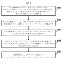
本実施例に係る管理情報の伝送方法は、図1に示すように、以下のステップS101〜ステップS105を含む。
Example 1
As shown in FIG. 1, the management information transmission method according to the present embodiment includes the following steps S101 to S105.
ステップS101:マスタ制御ユニットが、それとリンク確立ができた各非マスタ制御ユニットにVLANチャネルリソースを割り当て、割り当てたVLANチャネルリソースの情報を対応する非マスタ制御ユニットに送信する。 Step S101: The master control unit assigns a VLAN channel resource to each non-master control unit that has established a link with the master control unit, and transmits information on the assigned VLAN channel resource to the corresponding non-master control unit.
このステップにおいて、システムは、デフォルトで内部通信用VLANがあり、マスタ制御ユニットと他のユニットとがこのVLANを介して通信を行う。ネットワーク要素の内部において、マスタ制御ユニットと他のユニットとでC/Sアーキテクチャーがなされ、他のユニットがクライアントClientであって、積極的にマスタ制御ユニットとリンクを確立し、マスタ制御ユニットがサーバServerである。ここでいう他のユニットとは、他の非マスタ制御ユニットのことであり、非マスタ制御ユニットは、サービス伝送ユニット、レイヤ3ルーティングユニット及びアクセスユニットの少なくとも一方を含む。マスタ制御ユニットは、VLANチャネルリソースを割り当て、割り当てたVLANリソースの具体的な情報を、それとリンク確立ができた非マスタ制御ユニットに送信する。具体的には、マスタ制御ユニットがVLANチャネルリソースを割り当てることは、マスタ制御ユニット自身が予め設定したルールに従って行うことができるし、他の非マスタ制御ユニットとリンクを確立した後、他のユニットからのユニット情報を受け取り、該ユニット情報に基づいてVLANチャネルリソースを割り当てるようにすることもでき、VLANチャネルリソースの割り当ては、具体的には、どのようなユニットがどのチャネルに属するか、チャネルがどのぐらいあるか、等のように行われる。ここでいうユニット情報は、他のユニット自体の属性情報であり、好ましくは、該ユニット情報は、所在するカード基板のスロット番号、ユニットタイプ、必要とされるVLANチャネル数等の情報を含むことができ、ここでいうユニットタイプは、主として、該ユニットがどのようなユニットであるかを示し、具体的には、アクセスユニット、レイヤ3ルーティングユニット、レイヤ2スイッチングユニット、マスタ制御ユニット、サービス伝送ユニット等を含み、好ましくは、そのユニットタイプを具体的なシンボル又は数字で表すことができ、例えば、各ユニットのタイプを数字で表すと、1−アクセスユニット、2−レイヤ3ルーティングユニット、3−レイヤ2スイッチングユニット、4−マスタ制御ユニット、5−サービス伝送ユニットのように、アクセスユニットを1で表し、レイヤ3ルーティングユニットを2で表す等であり、もちろん、このような指示方式には限定されず、具体的な構成に基づいて指示することができる。このような必要とされるVLANチャネル数は、一般的には、サービス伝送ユニットの場合、サービス伝送ポート数によって決められ、それ以外のユニットの場合、デフォルトでは1つになる。例を挙げて説明すると、非マスタ制御ユニットがレイヤ3ルーティングユニット及びアクセスユニットであるとすれば、マスタ制御ユニットは、レイヤ3ルーティングユニットのユニット情報及びアクセスユニットのユニット情報を受け取った後、VLANチャネルをレイヤ3ルーティングユニット及びアクセスユニットに割り当てることになり、これにより、アクセスユニットからレイヤ3ルーティングユニットへの管理情報の伝送を実現する。
In this step, the system has an internal communication VLAN by default, and the master control unit communicates with other units via this VLAN. Within the network element, the master control unit and other units have a C / S architecture, the other unit is a client client, and actively establishes a link with the master control unit. Server. The other unit here is another non-master control unit, and the non-master control unit includes at least one of a service transmission unit, a layer 3 routing unit, and an access unit. The master control unit allocates VLAN channel resources and transmits specific information of the allocated VLAN resources to the non-master control unit that has established a link with it. Specifically, the master control unit can allocate the VLAN channel resource according to the rules set by the master control unit itself, or after establishing a link with another non-master control unit, It is also possible to receive VLAN unit resources and allocate VLAN channel resources based on the unit information. Specifically, VLAN channel resource allocation is based on what units belong to which channels and which channels It is done as if there is. The unit information here is attribute information of the other unit itself. Preferably, the unit information can include information such as the slot number of the card board where the card is located, the unit type, and the number of VLAN channels required. The unit type here mainly indicates what the unit is, and specifically includes an access unit, a layer 3 routing unit, a layer 2 switching unit, a master control unit, a service transmission unit, and the like. Preferably, the unit type can be represented by a specific symbol or number, for example, when each unit type is represented by a number, 1-access unit, 2-layer 3 routing unit, 3-layer 2 switching unit, 4-master control unit, 5-service transmission As in the knitted, it represents an
ステップS102:非マスタ制御ユニットが、割り当てたVLANチャネルリソースの情報に基づいて、VLANチャネルで伝送される管理情報の送信及び/又は受信を行うように構成される仮想ネットワークインターフェースを確立する。 Step S102: The non-master control unit establishes a virtual network interface configured to transmit and / or receive management information transmitted on the VLAN channel based on the information of the allocated VLAN channel resource.
このステップにおいて、非マスタ制御ユニットは、割り当てたVLANチャネルリソースの情報を受信して、対応する仮想ネットワークインターフェースを確立し、該ネットワークインターフェースは、VLANチャネルで伝送される管理情報の送信及び/又は受信を行う。ここでいうVLANチャネルリソースの情報は、該VLANチャネルのVLANid情報を含む。例えば、マスタ制御ユニットは、第3のVLANチャネルをアクセスユニット及びレイヤ3ルーティングユニットに割り当てることで、ネットワーク管理pcからレイヤ3ルーティングユニットへの伝送を実現し、この場合、マスタ制御ユニットは、VLANidをアクセスユニット及びレイヤ3ルーティングユニットに通知し、アクセスユニット及びレイヤ3ルーティングユニットがVLANidを受信した後、仮想ネットワークインターフェースを確立し、該仮想ネットワークインターフェースは、第3のVLANチャネルの伝送タグtag付き802.1Qメッセージ、即ち、802.1Qフォーマットでの管理情報のみを送受信する。レイヤ3ルーティングユニットについて、仮想ネットワークインターフェースが、さらに、ルーティングに対する出口ポートとして構成される。 In this step, the non-master control unit receives the allocated VLAN channel resource information and establishes a corresponding virtual network interface, which transmits and / or receives management information transmitted on the VLAN channel. I do. The VLAN channel resource information here includes VLANid information of the VLAN channel. For example, the master control unit realizes transmission from the network management pc to the layer 3 routing unit by assigning the third VLAN channel to the access unit and the layer 3 routing unit. In this case, the master control unit sets the VLANid to After notifying the access unit and the layer 3 routing unit and receiving the VLANid, the access unit and the layer 3 routing unit establish a virtual network interface, and the virtual network interface is attached with a transmission tag tag of the third VLAN channel. Only 1Q message, that is, management information in the 802.1Q format is transmitted and received. For the layer 3 routing unit, the virtual network interface is further configured as an egress port for routing.
ステップS103:マスタ制御ユニットが、レイヤ2スイッチングユニットに対してVLANチャネルを確立するよう通知する。 Step S103: The master control unit notifies the layer 2 switching unit to establish a VLAN channel.
このステップにおいて、マスタ制御ユニットは、VLANチャネルリソースを割り当てた後、レイヤ2スイッチングユニットに対して対応するVLANチャネルを確立するよう通知し、例えば、マスタ制御ユニットは、第1のVLANチャネル及び第2のVLANチャネルを割り当てると、レイヤ2スイッチングユニットに対して第1のVLANチャネル及び第2のVLANチャネルを確立するよう通知する。 In this step, after allocating the VLAN channel resource, the master control unit notifies the layer 2 switching unit to establish the corresponding VLAN channel. For example, the master control unit transmits the first VLAN channel and the second VLAN channel. When the first VLAN channel is assigned, the layer 2 switching unit is notified to establish the first VLAN channel and the second VLAN channel.
ステップS104:レイヤ2スイッチングユニットが、VLANチャネルを確立し、このVLANチャネルに対応するユニットの物理ポートをタグの形でVLANチャネルに加える。 Step S104: The layer 2 switching unit establishes a VLAN channel and adds the physical port of the unit corresponding to this VLAN channel to the VLAN channel in the form of a tag.
このステップにおいて、レイヤ2スイッチングユニットは、マスタ制御ユニットからの通知を受信した後、対応するVLANチャネルを確立し、該チャネルを開く。例えば、レイヤ2スイッチングユニットは、レイヤ3ルーティングユニットとアクセスユニットとの間の第3のVLANチャネルを確立し、ポートportA及びポートportBがレイヤ3ルーティングユニット及びアクセスユニットの物理ポートであり、すると、portA及びportBがタグtagの形で第3のVLANチャネルに加えられ、これにより、アクセスユニットとレイヤ3ルーティングユニットとの第3のVLANチャネルを開く。 In this step, after receiving the notification from the master control unit, the layer 2 switching unit establishes the corresponding VLAN channel and opens the channel. For example, the layer 2 switching unit establishes a third VLAN channel between the layer 3 routing unit and the access unit, and port port A and port port B are physical ports of the layer 3 routing unit and access unit. And portB are added to the third VLAN channel in the form of a tag tag, thereby opening the third VLAN channel of the access unit and the layer 3 routing unit.
ステップS105:管理情報をVLANチャネルで伝送する。 Step S105: The management information is transmitted through the VLAN channel.
このステップにおいて、VLANチャネルを確立して開いた後、管理情報を該VLANチャネルで各ユニットに伝送することができ、各ユニット及び各ネットワーク要素間の通信及び管理を行うことができる。例えば、アクセスユニットが管理情報をレイヤ3ルーティングユニットに伝送しようとすれば、アクセスユニットは、該管理情報をレイヤ3ルーティングユニットとアクセスユニットとの間の第3のVLANチャネルでレイヤ3ルーティングユニットに伝送する。 In this step, after establishing and opening the VLAN channel, management information can be transmitted to each unit over the VLAN channel, and communication and management between each unit and each network element can be performed. For example, if the access unit attempts to transmit management information to the layer 3 routing unit, the access unit transmits the management information to the layer 3 routing unit over a third VLAN channel between the layer 3 routing unit and the access unit. To do.
レイヤ3ルーティングユニットは、ipに基づくレイヤ3ルーティング機能を担い、その内部にルーティングプロトコルが実行され、ネットワーク全体のルーティングテーブルを計算するものであり、該ユニットは、ソフトウェアによって実現されることができるし、L3転送機能を持つスイッチチップによって実現されることもできる。VLANに基づく管理情報は、主にそのipポートに基づく情報であり、さらに、上記ステップS104において、主として、レイヤ3ルーティングユニットと他のインタラクティブユニットとの間のVLANチャネルを確立し、ここでいうインタラクティブユニットがマスタ制御ユニットであってもよいし、他の非マスタ制御ユニットであってもよい。具体的には、インタラクティブユニットがサービス伝送ユニットとマスタ制御ユニットとを備える場合、レイヤ3ルーティングユニットとインタラクティブユニットとの間のVLANチャネルを確立することは、レイヤ3ルーティングユニットとサービス伝送ユニットとの間の第1のVLANチャネルを確立することと、レイヤ3ルーティングユニットとマスタ制御ユニットとの間の第2のVLANチャネルを確立することと、を含む。インタラクティブユニットがアクセスユニットをさらに備え、この場合、レイヤ3ルーティングユニットとインタラクティブユニットとの間のVLANチャネルを確立することは、レイヤ3ルーティングユニットとアクセスユニットとの間の第3のVLANチャネルを確立することをさらに含む。なお、一般的に、アクセスユニットを備えるのはアクセスネットワーク要素であり、アクセスユニットがないのは非アクセスネットワーク要素である。 The layer 3 routing unit has a layer 3 routing function based on ip, a routing protocol is executed therein, and a routing table for the entire network is calculated. The unit can be realized by software. It can also be realized by a switch chip having an L3 transfer function. The management information based on the VLAN is mainly information based on the ip port. Furthermore, in step S104, the VLAN channel is mainly established between the layer 3 routing unit and the other interactive unit, and the interactive information referred to here is used. The unit may be a master control unit or another non-master control unit. Specifically, if the interactive unit comprises a service transmission unit and a master control unit, establishing a VLAN channel between the layer 3 routing unit and the interactive unit is between the layer 3 routing unit and the service transmission unit. Establishing a first VLAN channel and establishing a second VLAN channel between the layer 3 routing unit and the master control unit. The interactive unit further comprises an access unit, where establishing a VLAN channel between the layer 3 routing unit and the interactive unit establishes a third VLAN channel between the layer 3 routing unit and the access unit. In addition. In general, an access network element includes an access unit, and a non-access network element does not include an access unit.
さらに、上記ステップS105において、管理情報をVLANチャネルで伝送することは、サービス伝送ユニットがサービスチャネルから管理情報を取得し、第1のVLANチャネルを介してレイヤ3ルーティングユニットに伝送することと、レイヤ3ルーティングユニットが管理情報を処理して、対応するVLANチャネルを選択して伝送することと、を含む。管理情報をVLANチャネルで伝送することは、アクセスユニットがウェブマスター(ネットワーク管理)から管理情報を取得し、第3のVLANチャネルを介してレイヤ3ルーティングユニットに伝送することと、レイヤ3ルーティングユニットが管理情報を伝送すること、及び/又は、サービス伝送ユニットがサービスチャネルから管理情報を取得し、第1のVLANチャネルを介してレイヤ3ルーティングユニットに伝送することと、レイヤ3ルーティングユニットが管理情報を伝送すること、をさらに含む。さらに、レイヤ3ルーティングユニットが管理情報を処理して、対応するVLANチャネルを選択して伝送することは、レイヤ3ルーティングユニットが、管理情報のポートがローカルネットワーク要素であるか否かを判定することと、YESであれば、管理情報を第2のVLANチャネルでマスタ制御ユニットに伝送し、NOであれば、管理情報を第1のVLANチャネルで、管理情報をサービスチャネルで他のネットワーク要素に転送するサービス伝送ユニットに伝送することと、を含む。管理情報を具体的にどのユニットに伝送するかに基づいて、対応するVLANチャネルを選択して伝送することは、特別なハードウェア又は新しい物理チャネルによるサポートが必要とされず、レイヤ2ネットワークにおけるVLANに基づく転送のみによって、ネットワーク全体の管理を実現することができ、構成フローを簡略化し、設計及びハードウェアを低コスト化し、複数種のシステムにおけるDCNネットワーキングのために方法及びシステムを提供すると、理解されるべきである。 Furthermore, in step S105, transmitting the management information through the VLAN channel means that the service transmission unit acquires the management information from the service channel and transmits the management information to the layer 3 routing unit via the first VLAN channel. 3 routing units process the management information and select and transmit the corresponding VLAN channel. The management information is transmitted through the VLAN channel when the access unit acquires management information from the web master (network management) and transmits the management information to the layer 3 routing unit via the third VLAN channel. Transmitting the management information, and / or the service transmission unit obtaining the management information from the service channel and transmitting it to the layer 3 routing unit via the first VLAN channel, and the layer 3 routing unit transmitting the management information Transmitting further. Further, the layer 3 routing unit processes the management information and selects and transmits the corresponding VLAN channel, so that the layer 3 routing unit determines whether the management information port is a local network element. If YES, the management information is transmitted to the master control unit via the second VLAN channel, and if NO, the management information is transferred to the other network element via the first VLAN channel and the management information via the service channel. Transmitting to a service transmission unit. Based on the specific unit to which the management information is transmitted, selecting and transmitting the corresponding VLAN channel does not require support by special hardware or a new physical channel, and the VLAN in the layer 2 network It is understood that the entire network can be managed by only forwarding based on the network, simplifying the configuration flow, reducing design and hardware costs, and providing a method and system for DCN networking in multiple systems. It should be.
(実施例2)
本実施例に係る管理情報の伝送方法は、図2に示すように、VLANチャネルを確立するプロセスは、以下のステップS201〜ステップS205を含む。
(Example 2)
In the management information transmission method according to the present embodiment, as shown in FIG. 2, the process of establishing a VLAN channel includes the following steps S201 to S205.
ステップS201:非マスタ制御ユニットとマスタ制御ユニットとがリンクを確立する。 Step S201: The non-master control unit and the master control unit establish a link.
ステップS202:リンク確立に成功した後、マスタ制御ユニットが、VLANチャネルリソースを他のユニットに割り当てる。 Step S202: After successful link establishment, the master control unit allocates VLAN channel resources to other units.
ステップS203:他のユニットがVLANチャネルリソースを受け取った後、仮想ネットワークインターフェースを確立する。 Step S203: After the other unit receives the VLAN channel resource, the virtual network interface is established.
ステップS204:レイヤ2スイッチングユニットがVLANチャネルを確立し、ユニット間の通信リンクを開く。 Step S204: The layer 2 switching unit establishes a VLAN channel and opens a communication link between the units.
ステップS205:サービス伝送ユニットが無効化された後、マスタ制御ユニットが、VLANチャネルリソースを回収し、他のユニットに対してVLANチャネルを削除するよう通知する。 Step S205: After the service transmission unit is invalidated, the master control unit collects the VLAN channel resource and notifies other units to delete the VLAN channel.
(実施例3)
本発明をよりよく説明するために、以下、図3〜5及び具体的な実施例を結合しながら本発明を詳しく説明する。
(Example 3)
In order to better explain the present invention, the present invention will be described in detail below with reference to FIGS. 3 to 5 and specific examples.
アクセスユニット、マスタ制御ユニット、レイヤ3ルーティングユニット、サービス伝送ユニットが内部イーサネット(登録商標)バス又は操作システムの内部通信を介してレイヤ2スイッチングユニットと通信する。システムにおけるユニットはいずれもソフトウェアで実現されることができ、通常、カード基板エンティティに配置され、1つのカード基板には1つのユニットが配置されてもよいし、複数のユニットが配置されてもよい。カード基板エンティティは、ユニット間の通信のためにネットワークインターフェースやtcp/ipプロトコルスタック、操作システム等を提供し、各ユニットの管理メッセージをイーサネットメッセージとしてカプセル化して伝送するように構成される。各カード基板のmac及びipはスロット番号によって自動的に生成され、レイヤ2/3ネットワーク通信の識別子とされる。 The access unit, master control unit, layer 3 routing unit, and service transmission unit communicate with the layer 2 switching unit via the internal Ethernet bus or the internal communication of the operating system. All units in the system can be realized by software, and are usually arranged in a card board entity, and one unit may be arranged in one card board, or a plurality of units may be arranged. . The card board entity provides a network interface, a tcp / ip protocol stack, an operation system, etc. for communication between units, and is configured to encapsulate and transmit management messages of each unit as Ethernet messages. The “mac” and “ip” of each card board are automatically generated by the slot number and used as an identifier for layer 2/3 network communication.
図3に示すように、システムにおいて、デフォルトでは内部通信用VLANがあり、マスタ制御ユニットと他のユニットとがこのVLANを介して通信を行う。ネットワーク要素の内部において、マスタ制御ユニットと他のユニットとでC/Sアーキテクチャーがなされ、他のユニットがクライアントClientであって、積極的にマスタ制御ユニットとリンクを確立し、マスタ制御ユニットがサーバServerである。リンク確立に成功した後、他のユニットが自体の情報をマスタ制御ユニットに伝送する。その情報は、所在するカード基板のスロット番号、ユニットタイプ(1−アクセスユニット、2−レイヤ3ルーティングユニット、3−レイヤ2スイッチングユニット、4−マスタ制御ユニット、5−サービス伝送ユニット)、必要とされるVLANチャネル数(サービス伝送ユニットの場合、サービス伝送ポート数によって決められ、それ以外のユニットの場合、デフォルトでは1つになる)を含む。 As shown in FIG. 3, in the system, there is a VLAN for internal communication by default, and the master control unit and other units communicate via this VLAN. Within the network element, the master control unit and other units have a C / S architecture, the other unit is a client client, and actively establishes a link with the master control unit. Server. After successfully establishing the link, the other units transmit their information to the master control unit. The information is required slot number of card board, unit type (1-access unit, 2-layer 3 routing unit, 3-layer 2 switching unit, 4-master control unit, 5-service transmission unit). VLAN channel number (in the case of a service transmission unit, it is determined by the number of service transmission ports; in other units, it is one by default).
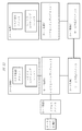
他のユニットから送信された情報を受け取った後、マスタ制御ユニットは、ユニット情報に基づいてVLANチャネルリソースを割り当て、他のユニットに対してVLANチャネルを確立するよう通知する。本実施例における第1のVLANチャネルをVLANCチャネルとし、第2のVLANチャネルをVLANBチャネルとし、第3のVLANチャネルをVLANAチャネルとすることを例にして説明する。図4に示すように、アクセスネットワーク要素は、VLANAがアクセスユニット及びレイヤ3ルーティングユニットに割り当てられることで、ネットワーク管理pcからレイヤ3ルーティングユニットへの伝送を実現し、この場合、マスタ制御ユニットは、VLANidをアクセスユニット及びレイヤ3ルーティングユニットに通知し、アクセスユニット及びレイヤ3ルーティングユニットがVLANidを受け取った後、仮想ネットワークインターフェースを確立し、該仮想ネットワークインターフェースは、VLANA tag付き802.1Qメッセージのみを送受信し、レイヤ3ルーティングユニットについて、仮想ネットワークインターフェースが、さらに、ルーティングに対する出口ポートとして構成される。同様に、VLANCがサービス伝送ユニット及びレイヤ3ルーティングユニットに割り当てられることで、ネットワーク要素間の情報伝送を実現し、VLANBがレイヤ3ルーティングユニット及びマスタ制御ユニットに割り当てられることで、レイヤ3ルーティングユニットからローカルネットワーク要素のマスタ制御ユニットへの情報伝送を実現する。最後に、マスタ制御ユニットは、レイヤ2スイッチングユニットに対してVLANチャネルを確立するよう通知し、対応するユニットの物理ポートをVLANに加え、レイヤ2スイッチングユニットがVLANAを確立し、portA及びportBをtagの形でVLANAに加え、これにより、アクセスユニットとレイヤ3ルーティングユニットとのVLANAチャネルが開かれる。そして、同様な方法により、portA及びportCをtagの形でVLANBに加え、VLANBチャネルを開くとともに、portA及びportDをtagの形でVLANCに加え、VLANCチャネルを開く。非アクセスネットワーク要素について、図5に示すように、具体的には、上述した通りVLANBチャネル及びVLANCチャネルを確立し、該VLANBチャネル及びVLANCチャネルを開く。 After receiving the information transmitted from the other unit, the master control unit allocates the VLAN channel resource based on the unit information and notifies the other unit to establish the VLAN channel. In this embodiment, the first VLAN channel is a VLANC channel, the second VLAN channel is a VLANB channel, and the third VLAN channel is a VLANA channel. As shown in FIG. 4, the access network element realizes transmission from the network management pc to the layer 3 routing unit by assigning VLANA to the access unit and the layer 3 routing unit. In this case, the master control unit The VLANid is notified to the access unit and the layer 3 routing unit, and after the access unit and the layer 3 routing unit receive the VLANid, a virtual network interface is established, and the virtual network interface transmits and receives only the 802.1Q message with VLANA tag. However, for the layer 3 routing unit, the virtual network interface is further configured as an egress port for routing. Similarly, the VLANC is assigned to the service transmission unit and the layer 3 routing unit to realize information transmission between network elements, and the VLANB is assigned to the layer 3 routing unit and the master control unit, so that the layer 3 routing unit Realizes information transmission to the master control unit of the local network element. Finally, the master control unit notifies the layer 2 switching unit to establish a VLAN channel, adds the physical port of the corresponding unit to the VLAN, the layer 2 switching unit establishes VLANA, and tag portA and portB. In addition to VLANA, this opens the VLANA channel between the access unit and the layer 3 routing unit. Then, by the same method, portA and portC are added to VLANB in the form of tag, VLANB channel is opened, and portA and portD are added to VLANC in the form of tag to open VLANC channel. For the non-access network element, as shown in FIG. 5, specifically, the VLANB channel and the VLANC channel are established as described above, and the VLANB channel and the VLANC channel are opened.
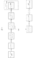
VLANチャネルが開かれた後、管理メッセージ、即ち管理情報の処理フローは、図6に示す通りであり、ネットワーク管理メッセージがPCからアクセスユニットを介してレイヤ2スイッチングユニットに伝送され、アクセスユニットが管理メッセージを802.1Q形式にカプセル化し、VLANid=VLANAになる。レイヤ2スイッチングユニットが802.1Qタグに基づいて、VLANAでレイヤ3ルーティングユニットに伝送する。そして、レイヤ3ルーティングユニットがdipによってルーティングテーブルからポートを見出し、ローカルネットワーク要素であれば、メッセージを直接VLANBにカプセル化してマスタ制御ユニットに伝送する。遠隔ネットワーク要素であれば、メッセージをVLANCにカプセル化してサービス伝送ユニットに伝送し、サービス伝送ユニットにおけるメッセージ処理論理によって802.1Qタグを取り外し、標準のイーサネットパケットに復元しサービスチャネル1にカプセル化して伝送する(サービスチャネルがOTNサービスであれば、GCCにカプセル化し、サービスチャネルがイーサネットサービスであれば、サービスVLANにカプセル化し、・・・)。さらに、図7には、非アクセスネットワーク要素の管理情報の処理フローを示し、相手側サービス伝送ユニットが、サービスチャネルからイーサネットメッセージを解析した後、802.1Qタグを付加し、VLANidがVLANC’になり、そしてレイヤ2スイッチングユニットに送信し、レイヤ2スイッチングユニットがVLANC’にてメッセージを転送し、ローカルネットワーク要素であれば、メッセージを直接VLANB’にカプセル化してマスタ制御ユニットに伝送する。遠隔ネットワーク要素であれば、メッセージをVLANC’にカプセル化してサービス伝送ユニットに伝送し、サービス伝送ユニットにおけるメッセージ処理論理によって802.1Qタグを取り外し、標準のイーサネットパケットに復元しサービスチャネル2にカプセル化して伝送する。 After the VLAN channel is opened, the processing flow of the management message, that is, management information is as shown in FIG. 6, and the network management message is transmitted from the PC to the layer 2 switching unit via the access unit. Encapsulate the message in 802.1Q format and VLANid = VLANA. The layer 2 switching unit transmits to the layer 3 routing unit by VLANA based on the 802.1Q tag. Then, the layer 3 routing unit finds the port from the routing table by dip, and if it is a local network element, the message is directly encapsulated in VLANB and transmitted to the master control unit. If it is a remote network element, the message is encapsulated in VLANC and transmitted to the service transmission unit, the 802.1Q tag is removed by the message processing logic in the service transmission unit, restored to a standard Ethernet packet, and encapsulated in service channel 1 (If the service channel is an OTN service, it is encapsulated in GCC, and if the service channel is an Ethernet service, it is encapsulated in a service VLAN.) Further, FIG. 7 shows a processing flow of management information of the non-access network element. After the partner service transmission unit analyzes the Ethernet message from the service channel, an 802.1Q tag is added, and VLANid is set to VLANC ′. Then, the message is transmitted to the layer 2 switching unit, and the layer 2 switching unit transfers the message by VLANC ′. If it is a local network element, the message is directly encapsulated in VLANB ′ and transmitted to the master control unit. If it is a remote network element, the message is encapsulated in VLANC 'and transmitted to the service transmission unit, the 802.1Q tag is removed by the message processing logic in the service transmission unit, restored to a standard Ethernet packet, and encapsulated in service channel 2 And transmit.
(実施例4)
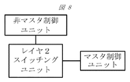
本実施例に係る管理情報の伝送システムは、図8に示すように、マスタ制御ユニットと、非マスタ制御ユニットと、レイヤ2スイッチングユニットと、を備える。マスタ制御ユニットが、非マスタ制御ユニットのリンク要求を受信し、非マスタ制御ユニットとリンクを確立した後、リンク確立ができた各非マスタ制御ユニットにVLANチャネルリソースを割り当て、割り当てたVLANチャネルリソースの情報を対応する非マスタ制御ユニットに送信する。非マスタ制御ユニットが、マスタ制御ユニットによって割り当てられたVLANチャネルリソースの情報を受信し、VLANチャネルリソースの情報に基づいて、VLANチャネルで伝送される管理情報の送信及び/又は受信を行う仮想ネットワークインターフェースを確立する。マスタ制御ユニットが、VLANチャネルを確立する旨の通知情報をレイヤ2スイッチングユニットへ送信する。レイヤ2スイッチングユニットが、通知情報を受信し、通知情報に基づいてVLANチャネルを確立し、VLANチャネルに対応するユニットの物理ポートをタグの形で、管理情報を伝送するように構成されるVLANチャネルに加える。
Example 4
As shown in FIG. 8, the management information transmission system according to the present embodiment includes a master control unit, a non-master control unit, and a layer 2 switching unit. After the master control unit receives the link request of the non-master control unit and establishes a link with the non-master control unit, a VLAN channel resource is allocated to each non-master control unit that has established the link, and the assigned VLAN channel resource Send information to the corresponding non-master control unit. A virtual network interface in which a non-master control unit receives information on VLAN channel resources allocated by the master control unit, and transmits and / or receives management information transmitted on the VLAN channel based on the information on VLAN channel resources Establish. The master control unit transmits notification information to the effect that the VLAN channel is established to the layer 2 switching unit. A VLAN channel configured such that the layer 2 switching unit receives notification information, establishes a VLAN channel based on the notification information, and transmits management information in the form of a tag to the physical port of the unit corresponding to the VLAN channel Add to.
さらに、非マスタ制御ユニットが、レイヤ3ルーティングユニットを備え、レイヤ2スイッチングユニットが、通知メッセージに基づいて、レイヤ3ルーティングユニットとインタラクティブユニットとの間のVLANチャネルを確立する。 Further, the non-master control unit comprises a layer 3 routing unit, and the layer 2 switching unit establishes a VLAN channel between the layer 3 routing unit and the interactive unit based on the notification message.
さらに、インタラクティブユニットが、マスタ制御ユニットとサービス伝送ユニットとを備え、レイヤ2スイッチングユニットは、さらに、レイヤ3ルーティングユニットとサービスチャネルとの間の第1のVLANチャネルを確立するとともに、レイヤ3ルーティングユニットとマスタ制御ユニットとの間の第2のVLANチャネルを確立するように構成される。 Further, the interactive unit comprises a master control unit and a service transmission unit, and the layer 2 switching unit further establishes a first VLAN channel between the layer 3 routing unit and the service channel, and the layer 3 routing unit And a second VLAN channel between the master control unit and the master control unit.
さらに、インタラクティブユニットが、アクセスユニットをさらに備え、レイヤ2スイッチングユニットは、さらに、レイヤ3ルーティングユニットとアクセスユニットとの間の第3のVLANチャネルを確立するように構成される。 Further, the interactive unit further comprises an access unit, and the layer 2 switching unit is further configured to establish a third VLAN channel between the layer 3 routing unit and the access unit.
さらに、サービス伝送ユニットが、サービスチャネルから管理情報を取得し、第1のVLANチャネルを介してレイヤ3ルーティングユニットに伝送し、レイヤ3ルーティングユニットが管理情報を受信・処理し、対応するVLANチャネルを選択して伝送する。 Further, the service transmission unit obtains management information from the service channel, transmits it to the layer 3 routing unit via the first VLAN channel, and the layer 3 routing unit receives and processes the management information, and sets the corresponding VLAN channel. Select and transmit.
さらに、アクセスユニットがウェブマスター(ネットワーク管理)から管理情報を取得し、第3のVLANチャネルを介してレイヤ3ルーティングユニットに伝送し、レイヤ3ルーティングユニットが管理情報を受信・処理し、対応するVLANチャネルを選択して伝送する、及び/又は、サービス伝送ユニットがサービスチャネルから管理情報を取得し、第1のVLANチャネルを介してレイヤ3ルーティングユニットに伝送し、レイヤ3ルーティングユニットが管理情報を受信・処理し、対応するVLANチャネルを選択して伝送する。 Further, the access unit obtains management information from the web master (network management) and transmits it to the layer 3 routing unit via the third VLAN channel. The layer 3 routing unit receives and processes the management information, and the corresponding VLAN. Select and transmit the channel, and / or the service transmission unit acquires management information from the service channel, transmits it to the layer 3 routing unit via the first VLAN channel, and the layer 3 routing unit receives the management information Process and select the corresponding VLAN channel for transmission.
さらに、レイヤ3ルーティングユニットが、管理情報のポートがローカルネットワーク要素であるか否かを判定し、YESであれば、管理情報を第2のVLANチャネルでマスタ制御ユニットに伝送し、NOであれば、管理情報を第1のVLANチャネルでサービス伝送ユニットに伝送し、サービス伝送ユニットは、さらに、管理情報をサービスチャネルで他のネットワーク要素に転送するように構成される。 Further, the layer 3 routing unit determines whether the management information port is a local network element. If YES, the management information is transmitted to the master control unit via the second VLAN channel. The management information is transmitted to the service transmission unit on the first VLAN channel, and the service transmission unit is further configured to transfer the management information to other network elements on the service channel.
本実施例におけるレイヤ2スイッチングユニットは、レイヤ2スイッチチップによってVLANに基づくレイヤ2転送機能を担うとともに、他のユニットのアクセスを提供する。レイヤ3ルーティングユニットは、ipに基づくレイヤ3ルーティング機能を担い、その内部にルーティングプロトコルが実行され、ネットワーク全体のルーティングテーブルを計算するものであり、該ユニットは、ソフトウェアによって実現されることができるし、L3転送機能を持つスイッチチップによって実現されることもできる。マスタ制御ユニットは、VLANチャネルリソースの管理及び各ユニットの管理を担い、ソフトウェアによって実現される。サービス伝送ユニットは、サービス伝送チャネルを提供し、チャネルポートのタイプは、OTN、PTN、SDH、イーサネット等を含むが、これには限定されず、該チャネルはさらにモニターリング情報を伝送するように構成され、内部FPGAによって、管理メッセージがサービス伝送チャネルに挿入され、OTNサービスがGCCに挿入され、PTNの場合単独のpwで行い、SDHが1つのタイムスロットに挿入され、イーサネットの場合単独のVLANで伝送される。アクセスユニットは、一般的には、アクセスネットワーク要素に用いられ、非アクセスネットワーク要素にとって必須ではなく、インターフェースからレイヤ2スイッチングユニットへのチャネルを提供することが要求され、ネットワーク管理pcがアクセスするように構成され、インターフェースタイプが限定されず、ネットワーク管理DCNのアクセスを提供することもできる。 The layer 2 switching unit in the present embodiment is responsible for the VLAN-based layer 2 forwarding function by the layer 2 switch chip and provides access to other units. The layer 3 routing unit has a layer 3 routing function based on ip, a routing protocol is executed therein, and a routing table for the entire network is calculated. The unit can be realized by software. It can also be realized by a switch chip having an L3 transfer function. The master control unit is responsible for managing VLAN channel resources and each unit, and is realized by software. The service transmission unit provides a service transmission channel, and channel port types include, but are not limited to, OTN, PTN, SDH, Ethernet, etc., and the channel is further configured to transmit monitoring information. The management message is inserted into the service transmission channel by the internal FPGA, the OTN service is inserted into the GCC, the PTN is performed with a single pw, the SDH is inserted into one time slot, and the Ethernet is a single VLAN. Is transmitted. Access units are generally used for access network elements and are not required for non-access network elements, but are required to provide a channel from the interface to the layer 2 switching unit, so that the network management pc can access them. It is configured, interface type is not limited, and network management DCN access can also be provided.
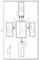
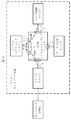
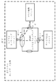
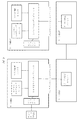
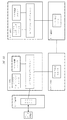
さらに、本実施例における各ユニットを自由に様々に組み合わせることができ、例えば、図9に示すように、アクセスユニット、レイヤ2スイッチングユニット、レイヤ3ルーティングユニット、マスタ制御ユニットがカード基板1に配置され、サービス伝送ユニットがカード基板2に配置され、同様に、相手側ネットワーク要素についても、マスタ制御ユニットがカード基板1’に配置され、サービス伝送ユニットがカード基板2’に配置される。また、図10に示すように、アクセスユニットがカード基板1に配置され、レイヤ2スイッチングユニット、レイヤ3ルーティングユニット、マスタ制御ユニットがカード基板2に配置され、サービス伝送ユニットがカード基板3に配置される。また、図11に示すように、アクセスユニット、レイヤ2スイッチングユニット、レイヤ3ルーティングユニット、マスタ制御ユニット、サービス伝送ユニットがそれぞれ1つのカード基板に配置され、即ち、アクセスユニットがカード基板1に配置され、レイヤ2スイッチングユニットがカード基板2に配置され、レイヤ3ルーティングユニットがカード基板3に配置され、マスタ制御ユニットがカード基板4に配置され、サービス伝送ユニットがカード基板5に配置され、対応する接続されるネットワーク要素のアクセスユニットがカード基板1’に配置され、レイヤ2スイッチングユニットがカード基板2’に配置され、レイヤ3ルーティングユニットがカード基板3’に配置され、マスタ制御ユニットがカード基板4’に配置され、サービス伝送ユニットがカード基板5’に配置される。さらに、図12に示すように、レイヤ3ルーティングユニット、マスタ制御ユニットが同一のカード基板に配置される一方、他のユニットがそれぞれ1つのカード基板に配置され、即ち、レイヤ3ルーティングユニット、マスタ制御ユニットがカード基板3に配置され、レイヤ2スイッチングユニットがカード基板4に配置され、アクセスユニットがカード基板1に配置され、サービス伝送ユニットがカード基板5に配置され、相手側の接続されるネットワーク要素のレイヤ3ルーティングユニット、マスタ制御ユニットがカード基板3’に配置され、レイヤ2スイッチングユニットがカード基板4’に配置され、サービス伝送ユニットがカード基板5’に配置される。もちろん、上記具体的な配置はこれには限定されず、具体的な状況に応じて具体的に配置することができる。
Furthermore, each unit in the present embodiment can be freely combined in various ways. For example, as shown in FIG. 9, an access unit, a layer 2 switching unit, a layer 3 routing unit, and a master control unit are arranged on the
当業者にとって、上述の本発明の各モジュール又は各ステップは汎用の計算装置によって実現することができ、単独の計算装置に集成させることができれば、複数の計算装置から構成されるネットワークに分布させることもでき、さらに計算装置で実行可能なプログラムのコードによって実現することもできるので、それらを記憶装置に格納して計算装置によって実行することができ、そして場合によって、示した又は説明したステップを上述と異なる手順で実行することができ、それぞれ集積回路モジュールに製作したり、これらのうち複数のモジュール又はステップを単独の集積回路モジュールに製作したりして実現することができることは、明らかなことである。このように、本発明は、如何なる特定のハードウェアとソフトウェアの結合に限定されない。 For those skilled in the art, each module or each step of the present invention described above can be realized by a general-purpose computing device, and if it can be assembled into a single computing device, it can be distributed over a network composed of a plurality of computing devices. Can also be implemented by code of a program executable on a computing device, so that they can be stored in a storage device and executed by the computing device, and optionally the steps shown or described are described above. Obviously, it can be executed by different procedures, and each can be manufactured in an integrated circuit module, or a plurality of modules or steps can be manufactured in a single integrated circuit module. is there. Thus, the present invention is not limited to any particular combination of hardware and software.
以上は、本発明の好適な実施例に過ぎず、本発明を限定することは意図していない。当業者であれば、本発明に様々な変更や変形が可能である。本発明の思想や原則内の如何なる修正、均等の置き換え、改良なども、本発明の保護範囲内に含まれるべきである。 The above are only preferred embodiments of the present invention and are not intended to limit the present invention. A person skilled in the art can make various changes and modifications to the present invention. Any modifications, equivalent replacements, improvements, etc. within the spirit and principle of the present invention should be included in the protection scope of the present invention.
上述したように、本発明の実施例に提供される管理情報の伝送方法及びシステムは、特別なハードウェア又は新しい物理チャネルによるサポートが必要とされず、レイヤ2ネットワークにおけるVLANに基づく転送のみによって、ネットワーク全体の管理情報の伝送を実現することができ、構成フローを簡略化し、設計及びハードウェアを低コスト化し、複数種のシステムにおけるDCNネットワーキングのために簡便な方法を提供するという有益な効果を有する。
As described above, the management information transmission method and system provided in the embodiments of the present invention does not require special hardware or support by a new physical channel, but only by VLAN-based forwarding in a layer 2 network. It is possible to realize the transmission of management information of the entire network, simplify the configuration flow, reduce the cost of design and hardware, and provide the beneficial effect of providing a simple method for DCN networking in multiple types of systems. Have.
Claims (11)
前記非マスタ制御ユニットが、前記VLANチャネルリソースの情報に基づいて、VLANチャネルで伝送される管理情報の送信及び/又は受信を行うように構成される仮想ネットワークインターフェースを確立することと、
マスタ制御ユニットが、レイヤ2スイッチングユニットに対してVLANチャネルを確立するよう通知することと、
レイヤ2スイッチングユニットが、VLANチャネルを確立し、前記VLANチャネルに対応するユニットの物理ポートをタグの形で前記VLANチャネルに加えることと、
管理情報を前記VLANチャネルで伝送することと、
を含む管理情報の伝送方法。 A master control unit assigns a VLAN channel resource to each non-master control unit that has established a link with the master control unit, and transmits information on the assigned VLAN channel resource to the corresponding non-master control unit;
Establishing a virtual network interface configured such that the non-master control unit is configured to transmit and / or receive management information transmitted on a VLAN channel based on the VLAN channel resource information;
The master control unit notifies the layer 2 switching unit to establish a VLAN channel;
A layer 2 switching unit establishes a VLAN channel and adds the physical port of the unit corresponding to the VLAN channel to the VLAN channel in the form of a tag;
Transmitting management information on the VLAN channel;
Management information transmission method.
前記レイヤ2スイッチングユニットがVLANチャネルを確立することは、レイヤ2スイッチングユニットによって、レイヤ3ルーティングユニットとインタラクティブユニットとの間のVLANチャネルを確立することを含む、請求項1に記載の管理情報の伝送方法。 The non-master control unit comprises a layer 3 routing unit;
The transmission of management information according to claim 1, wherein establishing the VLAN channel by the layer 2 switching unit comprises establishing a VLAN channel between the layer 3 routing unit and the interactive unit by the layer 2 switching unit. Method.
レイヤ3ルーティングユニットとインタラクティブユニットとの間のVLANチャネルを確立することは、前記レイヤ3ルーティングユニットと前記サービス伝送ユニットとの間の第1のVLANチャネルを確立するとともに、前記レイヤ3ルーティングユニットと前記マスタ制御ユニットとの間の第2のVLANチャネルを確立することを含む、請求項2に記載の管理情報の伝送方法。 The interactive unit includes a master control unit and a service transmission unit,
Establishing a VLAN channel between the layer 3 routing unit and the interactive unit establishes a first VLAN channel between the layer 3 routing unit and the service transmission unit, and the layer 3 routing unit and the interactive unit The method for transmitting management information according to claim 2, comprising establishing a second VLAN channel with the master control unit.
レイヤ3ルーティングユニットとインタラクティブユニットとの間のVLANチャネルを確立することは、前記レイヤ3ルーティングユニットとアクセスユニットとの間の第3のVLANチャネルを確立することをさらに含む、請求項3に記載の管理情報の伝送方法。 The interactive unit further comprises an access unit;
The establishing a VLAN channel between a layer 3 routing unit and an interactive unit further comprises establishing a third VLAN channel between the layer 3 routing unit and an access unit. Management information transmission method.
前記サービス伝送ユニットがサービスチャネルから管理情報を取得し、前記第1のVLANチャネルを介して前記レイヤ3ルーティングユニットに伝送することと、
前記レイヤ3ルーティングユニットが前記管理情報を処理し、対応する前記VLANチャネルを選択して伝送することと、を含む、請求項3に記載の管理情報の伝送方法。 The management information is transmitted through the VLAN channel.
The service transmission unit acquires management information from a service channel and transmits the management information to the layer 3 routing unit via the first VLAN channel;
The management information transmission method according to claim 3, comprising: the layer 3 routing unit processing the management information, and selecting and transmitting the corresponding VLAN channel.
前記アクセスユニットがウェブマスターから管理情報を取得し、前記第3のVLANチャネルを介して前記レイヤ3ルーティングユニットに伝送することと、前記レイヤ3ルーティングユニットが前記管理情報を処理して、対応する前記VLANチャネルを選択して伝送すること、
及び/又は、
前記サービス伝送ユニットがサービスチャネルから管理情報を取得し、前記第1のVLANチャネルを介して前記レイヤ3ルーティングユニットに伝送することと、前記レイヤ3ルーティングユニットが前記管理情報を処理して、対応する前記VLANチャネルを選択して伝送すること、を含む、請求項4に記載の管理情報の伝送方法。 The management information is transmitted through the VLAN channel.
The access unit obtains management information from a webmaster and transmits the management information to the layer 3 routing unit via the third VLAN channel; the layer 3 routing unit processes the management information; Selecting a VLAN channel for transmission;
And / or
The service transmission unit acquires management information from a service channel and transmits the management information to the layer 3 routing unit via the first VLAN channel; the layer 3 routing unit processes the management information and The management information transmission method according to claim 4, further comprising: selecting and transmitting the VLAN channel.
前記レイヤ3ルーティングユニットが、前記管理情報のポートがローカルネットワーク要素であるか否かを判定することと、
YESであれば、前記管理情報を前記第2のVLANチャネルで前記マスタ制御ユニットに伝送し、NOであれば、前記管理情報を前記第1のVLANチャネルで、前記管理情報をサービスチャネルで他のネットワーク要素に転送する前記サービス伝送ユニットに伝送することと、を含む、請求項5又は6に記載の管理情報の伝送方法。 The layer 3 routing unit processes the management information and selects and transmits the corresponding VLAN channel,
The layer 3 routing unit determines whether the port of the management information is a local network element;
If YES, the management information is transmitted to the master control unit over the second VLAN channel, and if NO, the management information is transmitted over the first VLAN channel and the management information is transmitted over the service channel. The management information transmission method according to claim 5, further comprising: transmitting to the service transmission unit to be transferred to a network element.
前記マスタ制御ユニットが、非マスタ制御ユニットのリンク要求を受信し、非マスタ制御ユニットとリンクを確立した後、リンク確立ができた各非マスタ制御ユニットにVLANチャネルリソースを割り当て、割り当てたVLANチャネルリソースの情報を対応する非マスタ制御ユニットに送信し、
前記非マスタ制御ユニットが、マスタ制御ユニットによって割り当てられたVLANチャネルリソースの情報を受信し、前記VLANチャネルリソースの情報に基づいて、VLANチャネルで伝送される管理情報の送信及び/又は受信を行うように構成される仮想ネットワークインターフェースを確立し、
前記マスタ制御ユニットが、前記レイヤ2スイッチングユニットに対して、VLANチャネルを確立する旨の通知情報を送信し、
前記レイヤ2スイッチングユニットが、前記通知情報を受信し、前記通知情報に基づいてVLANチャネルを確立し、前記VLANチャネルに対応するユニットの物理ポートをタグの形で、管理情報を伝送するように構成される前記VLANチャネルに加える、管理情報の伝送システム。 A master control unit, a non-master control unit, and a layer 2 switching unit;
After the master control unit receives the link request of the non-master control unit and establishes a link with the non-master control unit, a VLAN channel resource is allocated to each non-master control unit that has established the link, and the assigned VLAN channel resource To the corresponding non-master control unit,
The non-master control unit receives information on the VLAN channel resource allocated by the master control unit, and transmits and / or receives management information transmitted on the VLAN channel based on the information on the VLAN channel resource. Establish a virtual network interface configured in
The master control unit sends notification information to the effect that the VLAN channel is established to the layer 2 switching unit,
The layer 2 switching unit is configured to receive the notification information, establish a VLAN channel based on the notification information, and transmit management information in the form of a tag to a physical port of the unit corresponding to the VLAN channel. A management information transmission system to be added to the VLAN channel.
前記レイヤ2スイッチングユニットが、前記通知メッセージに基づいて、レイヤ3ルーティングユニットとインタラクティブユニットとの間のVLANチャネルを確立する、請求項8に記載の管理情報の伝送システム。 The non-master control unit comprises a layer 3 routing unit;
9. The management information transmission system according to claim 8, wherein the layer 2 switching unit establishes a VLAN channel between a layer 3 routing unit and an interactive unit based on the notification message.
前記レイヤ2スイッチングユニットは、さらに、前記レイヤ3ルーティングユニットと前記サービス伝送ユニットとの間の第1のVLANチャネルを確立するとともに、前記レイヤ3ルーティングユニットと前記マスタ制御ユニットとの間の第2のVLANチャネルを確立する、請求項9に記載の管理情報の伝送システム。 The interactive unit includes a master control unit and a service transmission unit,
The layer 2 switching unit further establishes a first VLAN channel between the layer 3 routing unit and the service transmission unit, and a second between the layer 3 routing unit and the master control unit. The management information transmission system according to claim 9, wherein a VLAN channel is established.
前記レイヤ2スイッチングユニットは、さらに、前記レイヤ3ルーティングユニットとアクセスユニットとの間の第3のVLANチャネルを確立するように構成される、請求項10に記載の管理情報の伝送システム。
The interactive unit further comprises an access unit;
11. The management information transmission system according to claim 10, wherein the layer 2 switching unit is further configured to establish a third VLAN channel between the layer 3 routing unit and an access unit.
Applications Claiming Priority (3)
| Application Number | Priority Date | Filing Date | Title |
|---|---|---|---|
| CN201410728240.3 | 2014-12-03 | ||
| CN201410728240.3A CN105656746A (en) | 2014-12-03 | 2014-12-03 | Management information transmitting method and system |
| PCT/CN2015/090311 WO2016086707A1 (en) | 2014-12-03 | 2015-09-22 | Method and system for transmitting management information |
Publications (1)
| Publication Number | Publication Date |
|---|---|
| JP2017536775A true JP2017536775A (en) | 2017-12-07 |
Family
ID=56090969
Family Applications (1)
| Application Number | Title | Priority Date | Filing Date |
|---|---|---|---|
| JP2017529320A Pending JP2017536775A (en) | 2014-12-03 | 2015-09-22 | Management information transmission method and system |
Country Status (4)
| Country | Link |
|---|---|
| EP (1) | EP3229414B1 (en) |
| JP (1) | JP2017536775A (en) |
| CN (1) | CN105656746A (en) |
| WO (1) | WO2016086707A1 (en) |
Families Citing this family (1)
| Publication number | Priority date | Publication date | Assignee | Title |
|---|---|---|---|---|
| CN105933142A (en) * | 2016-04-08 | 2016-09-07 | 邦彦技术股份有限公司 | Network element management method and device |
Citations (5)
| Publication number | Priority date | Publication date | Assignee | Title |
|---|---|---|---|---|
| US20030188003A1 (en) * | 2001-05-04 | 2003-10-02 | Mikael Sylvest | Method and apparatus for the provision of unified systems and network management of aggregates of separate systems |
| US20080267072A1 (en) * | 2007-04-27 | 2008-10-30 | Futurewei Technologies, Inc. | Data Communications Network for the Management of an Ethernet Transport Network |
| US20080270588A1 (en) * | 2007-04-27 | 2008-10-30 | Futurewei Technologies, Inc. | Verifying Management Virtual Local Area Network Identifier Provisioning Consistency |
| WO2014104277A1 (en) * | 2012-12-28 | 2014-07-03 | 日本電気株式会社 | Control apparatus, communication system, communication node control method and program |
| WO2014133015A1 (en) * | 2013-02-27 | 2014-09-04 | 日本電気株式会社 | Control apparatus, communication system, switch control method and program |
Family Cites Families (5)
| Publication number | Priority date | Publication date | Assignee | Title |
|---|---|---|---|---|
| CN101115006B (en) * | 2007-08-21 | 2010-08-25 | 杭州华三通信技术有限公司 | Three-layer packet forwarding method and routing device and two-layer switch module |
| CN102045184B (en) * | 2009-10-22 | 2012-09-05 | 华为技术有限公司 | Automatic management method for customer edge equipment and PE equipment |
| CN101984581A (en) * | 2010-11-04 | 2011-03-09 | 中兴通讯股份有限公司 | Method and system for opening data communication network |
| WO2011113398A1 (en) * | 2011-04-28 | 2011-09-22 | 华为技术有限公司 | Method and node for constructing management and maintenance channels |
| US8995424B2 (en) * | 2012-05-23 | 2015-03-31 | Dell Products L.P. | Network infrastructure provisioning with automated channel assignment |
-
2014
- 2014-12-03 CN CN201410728240.3A patent/CN105656746A/en not_active Withdrawn
-
2015
- 2015-09-22 JP JP2017529320A patent/JP2017536775A/en active Pending
- 2015-09-22 EP EP15864495.5A patent/EP3229414B1/en active Active
- 2015-09-22 WO PCT/CN2015/090311 patent/WO2016086707A1/en not_active Ceased
Patent Citations (5)
| Publication number | Priority date | Publication date | Assignee | Title |
|---|---|---|---|---|
| US20030188003A1 (en) * | 2001-05-04 | 2003-10-02 | Mikael Sylvest | Method and apparatus for the provision of unified systems and network management of aggregates of separate systems |
| US20080267072A1 (en) * | 2007-04-27 | 2008-10-30 | Futurewei Technologies, Inc. | Data Communications Network for the Management of an Ethernet Transport Network |
| US20080270588A1 (en) * | 2007-04-27 | 2008-10-30 | Futurewei Technologies, Inc. | Verifying Management Virtual Local Area Network Identifier Provisioning Consistency |
| WO2014104277A1 (en) * | 2012-12-28 | 2014-07-03 | 日本電気株式会社 | Control apparatus, communication system, communication node control method and program |
| WO2014133015A1 (en) * | 2013-02-27 | 2014-09-04 | 日本電気株式会社 | Control apparatus, communication system, switch control method and program |
Also Published As
| Publication number | Publication date |
|---|---|
| EP3229414B1 (en) | 2019-06-12 |
| EP3229414A1 (en) | 2017-10-11 |
| WO2016086707A1 (en) | 2016-06-09 |
| EP3229414A4 (en) | 2017-11-15 |
| CN105656746A (en) | 2016-06-08 |
Similar Documents
| Publication | Publication Date | Title |
|---|---|---|
| US11689497B2 (en) | Auto deploying network for virtual private cloud with heterogenous workloads | |
| EP3677009B1 (en) | Unified security policies across virtual private clouds with overlapping ip address blocks | |
| US10063470B2 (en) | Data center network system based on software-defined network and packet forwarding method, address resolution method, routing controller thereof | |
| US11102074B2 (en) | Software defined access fabric without subnet restriction to a virtual network | |
| CN106411664B (en) | A Metropolitan Area Network System | |
| CN102308523B (en) | Data communication network configuration method, gateway network element and data communication system | |
| US12126494B2 (en) | Providing interface between network management and slice management | |
| EP3491835A1 (en) | Method and apparatus for controlling data forwarding in pon | |
| EP3201777B1 (en) | Providing functional requirements for a network connection from a local library | |
| Alimi et al. | Enhancement of network performance of an enterprises network with VLAN | |
| CN103580909B (en) | A kind of hardware resource method for customizing and device | |
| KR101786620B1 (en) | Method, apparatus and computer program for subnetting of software defined network | |
| CN108259633B (en) | Method, system and device for realizing management message three-layer communication | |
| CN108965091B (en) | Network element management method and system based on VXLAN tunnel | |
| JP6603312B2 (en) | Allocating capacity for network connections to data streams based on type | |
| JP2017536775A (en) | Management information transmission method and system | |
| KR101404491B1 (en) | System and Method for dynamic bandwidth setting of subnet based on OpenFlow network | |
| US11916731B2 (en) | Identification of nodes included in a disaggregated system | |
| EP3228048B1 (en) | Method and apparatus for routing data to cellular network | |
| CN105391704A (en) | Configuration port isolation exchange equipment based on service type and application method | |
| CN121814455A (en) | VXLAN networking isolation method and system based on port identification | |
| CN115913443A (en) | Business processing method, network device, and computer-readable storage medium | |
| CN103580961A (en) | VLAN allocation method and device | |
| HK1241484B (en) | Providing functional requirements for a network connection from a local library |
Legal Events
| Date | Code | Title | Description |
|---|---|---|---|
| A621 | Written request for application examination |
Free format text: JAPANESE INTERMEDIATE CODE: A621 Effective date: 20180912 |
|
| A977 | Report on retrieval |
Free format text: JAPANESE INTERMEDIATE CODE: A971007 Effective date: 20190515 |
|
| A131 | Notification of reasons for refusal |
Free format text: JAPANESE INTERMEDIATE CODE: A131 Effective date: 20190521 |
|
| A02 | Decision of refusal |
Free format text: JAPANESE INTERMEDIATE CODE: A02 Effective date: 20191210 |