JP2017538111A - 検出器装置 - Google Patents
検出器装置 Download PDFInfo
- Publication number
- JP2017538111A JP2017538111A JP2017522033A JP2017522033A JP2017538111A JP 2017538111 A JP2017538111 A JP 2017538111A JP 2017522033 A JP2017522033 A JP 2017522033A JP 2017522033 A JP2017522033 A JP 2017522033A JP 2017538111 A JP2017538111 A JP 2017538111A
- Authority
- JP
- Japan
- Prior art keywords
- detector
- housing
- detector device
- heat
- spring
- Prior art date
- Legal status (The legal status is an assumption and is not a legal conclusion. Google has not performed a legal analysis and makes no representation as to the accuracy of the status listed.)
- Granted
Links
Images




Classifications
-
- G—PHYSICS
- G02—OPTICS
- G02B—OPTICAL ELEMENTS, SYSTEMS OR APPARATUS
- G02B21/00—Microscopes
- G02B21/24—Base structure
- G02B21/28—Base structure with cooling device
-
- G—PHYSICS
- G01—MEASURING; TESTING
- G01J—MEASUREMENT OF INTENSITY, VELOCITY, SPECTRAL CONTENT, POLARISATION, PHASE OR PULSE CHARACTERISTICS OF INFRARED, VISIBLE OR ULTRAVIOLET LIGHT; COLORIMETRY; RADIATION PYROMETRY
- G01J1/00—Photometry, e.g. photographic exposure meter
- G01J1/02—Details
- G01J1/0252—Constructional arrangements for compensating for fluctuations caused by, e.g. temperature, or using cooling or temperature stabilization of parts of the device; Controlling the atmosphere inside a photometer; Purge systems, cleaning devices
-
- G—PHYSICS
- G01—MEASURING; TESTING
- G01J—MEASUREMENT OF INTENSITY, VELOCITY, SPECTRAL CONTENT, POLARISATION, PHASE OR PULSE CHARACTERISTICS OF INFRARED, VISIBLE OR ULTRAVIOLET LIGHT; COLORIMETRY; RADIATION PYROMETRY
- G01J1/00—Photometry, e.g. photographic exposure meter
- G01J1/02—Details
- G01J1/0271—Housings; Attachments or accessories for photometers
-
- G—PHYSICS
- G01—MEASURING; TESTING
- G01J—MEASUREMENT OF INTENSITY, VELOCITY, SPECTRAL CONTENT, POLARISATION, PHASE OR PULSE CHARACTERISTICS OF INFRARED, VISIBLE OR ULTRAVIOLET LIGHT; COLORIMETRY; RADIATION PYROMETRY
- G01J1/00—Photometry, e.g. photographic exposure meter
- G01J1/02—Details
- G01J1/04—Optical or mechanical part supplementary adjustable parts
- G01J1/0403—Mechanical elements; Supports for optical elements; Scanning arrangements
-
- G—PHYSICS
- G01—MEASURING; TESTING
- G01J—MEASUREMENT OF INTENSITY, VELOCITY, SPECTRAL CONTENT, POLARISATION, PHASE OR PULSE CHARACTERISTICS OF INFRARED, VISIBLE OR ULTRAVIOLET LIGHT; COLORIMETRY; RADIATION PYROMETRY
- G01J1/00—Photometry, e.g. photographic exposure meter
- G01J1/02—Details
- G01J1/04—Optical or mechanical part supplementary adjustable parts
- G01J1/0407—Optical elements not provided otherwise, e.g. manifolds, windows, holograms, gratings
- G01J1/0448—Adjustable, e.g. focussing
-
- G—PHYSICS
- G02—OPTICS
- G02B—OPTICAL ELEMENTS, SYSTEMS OR APPARATUS
- G02B21/00—Microscopes
- G02B21/0004—Microscopes specially adapted for specific applications
- G02B21/002—Scanning microscopes
- G02B21/0024—Confocal scanning microscopes (CSOMs) or confocal "macroscopes"; Accessories which are not restricted to use with CSOMs, e.g. sample holders
- G02B21/008—Details of detection or image processing, including general computer control
-
- G—PHYSICS
- G02—OPTICS
- G02B—OPTICAL ELEMENTS, SYSTEMS OR APPARATUS
- G02B21/00—Microscopes
- G02B21/0096—Microscopes with photometer devices
-
- G—PHYSICS
- G02—OPTICS
- G02B—OPTICAL ELEMENTS, SYSTEMS OR APPARATUS
- G02B21/00—Microscopes
- G02B21/0004—Microscopes specially adapted for specific applications
- G02B21/002—Scanning microscopes
- G02B21/0024—Confocal scanning microscopes (CSOMs) or confocal "macroscopes"; Accessories which are not restricted to use with CSOMs, e.g. sample holders
- G02B21/0032—Optical details of illumination, e.g. light-sources, pinholes, beam splitters, slits, fibers
Landscapes
- Physics & Mathematics (AREA)
- General Physics & Mathematics (AREA)
- Spectroscopy & Molecular Physics (AREA)
- Optics & Photonics (AREA)
- Chemical & Material Sciences (AREA)
- Analytical Chemistry (AREA)
- Electromagnetism (AREA)
- Engineering & Computer Science (AREA)
- Computer Vision & Pattern Recognition (AREA)
- General Engineering & Computer Science (AREA)
- Studio Devices (AREA)
- Microscoopes, Condenser (AREA)
- Cameras Adapted For Combination With Other Photographic Or Optical Apparatuses (AREA)
- Accessories Of Cameras (AREA)
- Photometry And Measurement Of Optical Pulse Characteristics (AREA)
Abstract
Description
Claims (17)
- 光を受信して電気信号を形成するように構成されており、かつ、
検出器(3)と前記検出器(3)用のハウジング(4)とを備えている、
検出器装置において、
前記検出器(3)は、少なくとも部分的に前記ハウジング(4)内に、かつ、前記ハウジング(4)に対して相対的に可動に、配置されている、
ことを特徴とする検出器装置。 - 前記検出器(3)は、複数の検出器部品を有する、及び/又は、
前記検出器(3)は、個別に取り扱い可能な検出器モジュールとして構成されている、
請求項1に記載の検出器装置。 - 前記複数の検出器部品のうち1つは、放熱素子(13)又は能動冷却素子又はフォトカソード(10)又は光学部品又はレンズ(7,9)又は鏡(8)又は加速段である、
請求項2に記載の検出器装置。 - 前記検出器(3)は、特に線形のシフト方向(5)に沿ってガイドされて可動に配置されている、及び/又は、
前記ハウジング(4)は、特に線形のシフト方向(5)を定める、前記検出器(3)のガイド部を形成している、
請求項1から3までのいずれか1項に記載の検出器装置。 - a.前記検出器(3)は、ばね装置(15)の力に対して前記ハウジング(4)内に可動に配置されている、及び/又は、
b.前記検出器(3)の放熱素子(13)を検出器装置外の吸熱部(14)に押しつけるように構成及び設計されたばね装置(15)が設けられている、及び/又は、
c.前記検出器の放熱素子(13)を検出器装置外の吸熱部(14)に押しつけるばね装置(15)が設けられている、
請求項1から4までのいずれか1項に記載の検出器装置。 - 前記ばね装置(15)は、選択的に、前記ばね装置(15)が前記検出器(3)に力を作用させる押圧位置へ、又は、前記ばね装置(15)が前記検出器(3)に力を作用させない解放位置へ、移行可能である、
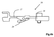
請求項5に記載の検出器装置。 - a.前記ばね装置(15)は、少なくとも1つのばね弾性を有する押圧レバー(16)を有する、及び/又は、
b.前記ばね装置(15)は、前記ハウジング(4)のねじ山に係合する締付ボルト(22)を有する、及び/又は、
c.前記ばね装置(15)は、ばね弾性を有する押圧レバー(16)の自由端部を前記ハウジング(4)に対する押圧位置へ到達させるために回動可能にし、かつ、前記ハウジング(4)に固定可能にする、締付ボルト(22)を有する、
請求項5又は6に記載の検出器装置。 - a.前記ばね弾性を有する押圧レバー(16)は、相互に枢動可能に連結された2つのレバー部材(17,18)を有する、及び/又は、
b.前記ばね弾性を有する押圧レバー(16)は、2つのレバー部材(17,18)を有し、前記2つのレバー部材(17,18)の一方が少なくとも前記押圧位置で前記検出器(3)に接する押圧カム(24)を有する、及び/又は、
c.前記ばね弾性を有する押圧レバー(16)は、前記自由端部に、前記締付ボルト(22)のボルトヘッド(21)に対する受容部を有する、及び/又は、
d.前記ばね弾性を有する押圧レバー(16)は、相互に枢動可能に連結された2つのレバー部材(17,18)を有しており、連結部は、前記押圧位置では、連結部ストッパに接するように伸展する、及び/又は、
e.前記ばね弾性を有する押圧レバー(16)は、相互に枢動可能に連結された2つのレバー部材(17,18)を有しており、連結部は、前記解放位置で屈曲する、及び/又は、前記押圧位置から前記解放位置への移行の際に自動的に屈曲する、
請求項7に記載の検出器装置。 - a.前記ハウジング(4)は、前記検出器の放熱素子(13)から検出器装置外の吸熱部(14)へ熱を放出可能な少なくとも1つの放熱開口(32)を有する、及び/又は、
b.前記ハウジング(4)は、前記検出器(3)の放熱素子(13)が貫通して突出する少なくとも1つの放熱開口(32)、又は、検出器装置外の吸熱部(14)が貫通して突出する少なくとも1つの放熱開口(32)、又は、前記検出器の放熱素子(13)を検出器装置外の吸熱部(14)に接触させる少なくとも1つの放熱開口(32)を有する、
請求項1から8までのいずれか1項に記載の検出器装置。 - 前記検出器(3)は、少なくとも1つのペルチエ素子(12)を有しており、前記放熱素子(13)は、前記ペルチエ素子(12)の高温側に熱伝導接触している、
請求項5から9までのいずれか1項に記載の検出器装置。 - 前記ハウジング(4)は、入射してくる検出すべき光(2)の光軸が貫通して延在する少なくとも1つの光入射開口を有する、
請求項1から10までのいずれか1項に記載の検出器装置。 - 前記光軸は、前記シフト方向(5)とは異なる配向を有する、及び/又は、
前記光軸と前記シフト方向(5)とは、相互に垂直に配置されている、
請求項11に記載の検出器装置。 - 前記ハウジング(4)は、前記ハウジングの内部を周状に延在する凸部(29)と、前記ハウジング(4)内へ突入する縁(31)を有するハウジングカバー(30)と、を有しており、
電子回路板(27)は、前記凸部(29)と前記縁(31)との間で、特には専ら、クランプによって保持されている、
請求項1から12までのいずれか1項に記載の検出器装置。 - 請求項1から13までのいずれか1項に記載の検出器装置(1)を少なくとも1つと、
前記検出器装置(1)に対する受容部(38)を有する検出器結合モジュール(37)と、
を備えた検出器システム。 - 前記検出器結合モジュール(37)は、吸熱部(14)を有する、
請求項14に記載の検出器システム。 - 請求項1から13までのいずれか1項に記載の検出器装置(1)のそれぞれに対する受容部(38)を複数備えている、
請求項14又は15に記載の検出器システム。 - 請求項1から13までのいずれか1項に記載の検出器装置(1)、及び/又は、
請求項14から16までのいずれか1項に記載の検出器システム(36)
を備えた顕微鏡、特に走査型顕微鏡又は共焦点走査型顕微鏡。
Applications Claiming Priority (3)
| Application Number | Priority Date | Filing Date | Title |
|---|---|---|---|
| LU92583A LU92583B1 (de) | 2014-10-22 | 2014-10-22 | Detektorvorrichtung |
| LULU92583 | 2014-10-22 | ||
| PCT/EP2015/074454 WO2016062798A1 (de) | 2014-10-22 | 2015-10-22 | Detektorvorrichtung |
Publications (2)
| Publication Number | Publication Date |
|---|---|
| JP2017538111A true JP2017538111A (ja) | 2017-12-21 |
| JP6714588B2 JP6714588B2 (ja) | 2020-06-24 |
Family
ID=51982729
Family Applications (1)
| Application Number | Title | Priority Date | Filing Date |
|---|---|---|---|
| JP2017522033A Active JP6714588B2 (ja) | 2014-10-22 | 2015-10-22 | 検出器装置 |
Country Status (4)
| Country | Link |
|---|---|
| US (1) | US10649193B2 (ja) |
| JP (1) | JP6714588B2 (ja) |
| LU (1) | LU92583B1 (ja) |
| WO (1) | WO2016062798A1 (ja) |
Families Citing this family (3)
| Publication number | Priority date | Publication date | Assignee | Title |
|---|---|---|---|---|
| USD1117392S1 (en) * | 2021-04-06 | 2026-03-10 | Leica Microsystems Cms Gmbh | Combination of accessories for a microscope |
| USD1064023S1 (en) * | 2021-10-05 | 2025-02-25 | Leica Microsystems Cms Gmbh | Accessory for a microscope |
| CN118089928B (zh) * | 2024-04-18 | 2024-07-09 | 青岛利恩迪电子科技发展有限公司 | 一种led灯可见光强度检测装置及使用方法 |
Citations (6)
| Publication number | Priority date | Publication date | Assignee | Title |
|---|---|---|---|---|
| JPH1041490A (ja) * | 1996-07-23 | 1998-02-13 | Hamamatsu Photonics Kk | 光検出装置 |
| JP2004163272A (ja) * | 2002-11-13 | 2004-06-10 | Hamamatsu Photonics Kk | 冷却式光検出装置 |
| JP2004279067A (ja) * | 2003-03-13 | 2004-10-07 | Toshiba Lighting & Technology Corp | センサユニットおよびセンサ装置 |
| JP2006112870A (ja) * | 2004-10-13 | 2006-04-27 | Hamamatsu Photonics Kk | 光検出装置 |
| US20100271695A1 (en) * | 2007-10-05 | 2010-10-28 | Leica Microsystems Cms Gmbh | Arrangement for analyzing microscopic and macroscopic preparations |
| JP2013040938A (ja) * | 2011-08-16 | 2013-02-28 | Leica Microsystems Cms Gmbh | 検出装置 |
Family Cites Families (8)
| Publication number | Priority date | Publication date | Assignee | Title |
|---|---|---|---|---|
| DE365388C (de) * | 1921-09-20 | 1922-12-14 | Pfeiffer Arthur | Hochvakuum-Spektrograph |
| US3999403A (en) * | 1974-12-06 | 1976-12-28 | Texas Instruments Incorporated | Thermal interface for cryogen coolers |
| JPS56147024A (en) * | 1980-04-16 | 1981-11-14 | Mitsubishi Electric Corp | Adjuster for mounting position of detector |
| US5124549A (en) * | 1990-10-15 | 1992-06-23 | Lectron Products, Inc. | Automatic headlamp dimmer with optical baffle |
| US6707028B2 (en) * | 2001-02-14 | 2004-03-16 | Spacesaver Corporation | Rotating light source system for detecting an obstruction in a space, for use in a mobile storage system |
| DE102009036066A1 (de) | 2009-08-04 | 2011-02-10 | Carl Zeiss Microimaging Gmbh | Optoelektronischer Detektor und Betriebsverfahren für einen solchen |
| DE202011109809U1 (de) * | 2011-08-16 | 2012-03-16 | Leica Microsystems Cms Gmbh | Detektorvorrichtung |
| JP5906068B2 (ja) * | 2011-11-25 | 2016-04-20 | キヤノン株式会社 | 読取装置およびプリント装置 |
-
2014
- 2014-10-22 LU LU92583A patent/LU92583B1/xx active
-
2015
- 2015-10-22 JP JP2017522033A patent/JP6714588B2/ja active Active
- 2015-10-22 US US15/520,854 patent/US10649193B2/en active Active
- 2015-10-22 WO PCT/EP2015/074454 patent/WO2016062798A1/de not_active Ceased
Patent Citations (6)
| Publication number | Priority date | Publication date | Assignee | Title |
|---|---|---|---|---|
| JPH1041490A (ja) * | 1996-07-23 | 1998-02-13 | Hamamatsu Photonics Kk | 光検出装置 |
| JP2004163272A (ja) * | 2002-11-13 | 2004-06-10 | Hamamatsu Photonics Kk | 冷却式光検出装置 |
| JP2004279067A (ja) * | 2003-03-13 | 2004-10-07 | Toshiba Lighting & Technology Corp | センサユニットおよびセンサ装置 |
| JP2006112870A (ja) * | 2004-10-13 | 2006-04-27 | Hamamatsu Photonics Kk | 光検出装置 |
| US20100271695A1 (en) * | 2007-10-05 | 2010-10-28 | Leica Microsystems Cms Gmbh | Arrangement for analyzing microscopic and macroscopic preparations |
| JP2013040938A (ja) * | 2011-08-16 | 2013-02-28 | Leica Microsystems Cms Gmbh | 検出装置 |
Also Published As
| Publication number | Publication date |
|---|---|
| US20180039057A1 (en) | 2018-02-08 |
| WO2016062798A1 (de) | 2016-04-28 |
| LU92583B1 (de) | 2016-04-25 |
| US10649193B2 (en) | 2020-05-12 |
| JP6714588B2 (ja) | 2020-06-24 |
Similar Documents
| Publication | Publication Date | Title |
|---|---|---|
| JP6423997B2 (ja) | 光源用熱処理装置及び光源装置 | |
| US7646419B2 (en) | Multiband camera system | |
| CN102954809B (zh) | 检测器设备 | |
| JP6714588B2 (ja) | 検出器装置 | |
| KR101602833B1 (ko) | 적외선 led 감시카메라 | |
| CN110035238B (zh) | 用于汽车安全和驾驶系统的紧凑型红外相机 | |
| US8128557B2 (en) | Endoscope with heat dissipating handle | |
| US8562176B2 (en) | Light diode with cooling body | |
| US10312050B2 (en) | Holder device for electron microscope | |
| JP2014016531A5 (ja) | ||
| CN107895684B (zh) | 离子源及质谱仪 | |
| US8303125B2 (en) | Focus apparatus of image measuring system | |
| US9297993B2 (en) | Ring illumination device for a microscope objective, and microscope objective | |
| JP2013229496A (ja) | 検査装置 | |
| CN104296873A (zh) | 一种光谱二向性测量系统 | |
| AU2018353833A1 (en) | Alignment assembly and method for multi-spectral optical systems | |
| KR102666965B1 (ko) | 카메라 모듈 및 차량 | |
| CN109029929A (zh) | 拍瓦级高功率激光系统靶面焦点精确定位的方法 | |
| JP5866173B2 (ja) | 防水形押込みカメラヘッド | |
| US9548586B2 (en) | Energy integrating device for split semiconductor laser diodes | |
| JP7079257B2 (ja) | ランプ挿入体を備えるモジュール式広帯域光源及びその使用方法 | |
| JP2004045192A (ja) | 照明装置 | |
| Barbis et al. | MAJIS/JUICE optical head: characterization campaign and derived performance test results | |
| US20150316244A1 (en) | Light-emitting means, in particular led module | |
| KR101490629B1 (ko) | 태양광 집광 모듈 |
Legal Events
| Date | Code | Title | Description |
|---|---|---|---|
| A621 | Written request for application examination |
Free format text: JAPANESE INTERMEDIATE CODE: A621 Effective date: 20181016 |
|
| A977 | Report on retrieval |
Free format text: JAPANESE INTERMEDIATE CODE: A971007 Effective date: 20190830 |
|
| A131 | Notification of reasons for refusal |
Free format text: JAPANESE INTERMEDIATE CODE: A131 Effective date: 20190930 |
|
| A601 | Written request for extension of time |
Free format text: JAPANESE INTERMEDIATE CODE: A601 Effective date: 20191220 |
|
| A521 | Request for written amendment filed |
Free format text: JAPANESE INTERMEDIATE CODE: A523 Effective date: 20200227 |
|
| TRDD | Decision of grant or rejection written | ||
| A01 | Written decision to grant a patent or to grant a registration (utility model) |
Free format text: JAPANESE INTERMEDIATE CODE: A01 Effective date: 20200507 |
|
| A61 | First payment of annual fees (during grant procedure) |
Free format text: JAPANESE INTERMEDIATE CODE: A61 Effective date: 20200605 |
|
| R150 | Certificate of patent or registration of utility model |
Ref document number: 6714588 Country of ref document: JP Free format text: JAPANESE INTERMEDIATE CODE: R150 |
|
| R250 | Receipt of annual fees |
Free format text: JAPANESE INTERMEDIATE CODE: R250 |
|
| R250 | Receipt of annual fees |
Free format text: JAPANESE INTERMEDIATE CODE: R250 |
|
| R250 | Receipt of annual fees |
Free format text: JAPANESE INTERMEDIATE CODE: R250 |