JP2018024006A - Additional processing head and processing machine - Google Patents
Additional processing head and processing machine Download PDFInfo
- Publication number
- JP2018024006A JP2018024006A JP2016158402A JP2016158402A JP2018024006A JP 2018024006 A JP2018024006 A JP 2018024006A JP 2016158402 A JP2016158402 A JP 2016158402A JP 2016158402 A JP2016158402 A JP 2016158402A JP 2018024006 A JP2018024006 A JP 2018024006A
- Authority
- JP
- Japan
- Prior art keywords
- additional processing
- nozzle
- tube
- workpiece
- processing head
- Prior art date
- Legal status (The legal status is an assumption and is not a legal conclusion. Google has not performed a legal analysis and makes no representation as to the accuracy of the status listed.)
- Granted
Links
Images


Landscapes
- Laser Beam Processing (AREA)
- Powder Metallurgy (AREA)
Abstract
【課題】周方向に移動するノズルに材料を供給する機構を、簡易な構成により実現するとともに、ノズルの移動に伴ってワークへの材料の供給量が変動することを抑制する付加加工用ヘッド、および、そのような付加加工用ヘッドを備える加工機械、を提供する。【解決手段】付加加工用ヘッドは、材料粉末が導入される連結部52と、ワークに向けて照射されるレーザ光311の周りで周方向に移動可能に設けられ、材料粉末を吐出するノズル78と、連結部52およびノズル78の間に設けられ、連結部52に導入された材料粉末をノズル78に向けて供給するチューブ81とを備える。チューブ81は、可撓性を有し、レーザ光311の周りで周回するように設けられる。【選択図】図5PROBLEM TO BE SOLVED: To realize a mechanism for supplying a material to a nozzle moving in the circumferential direction by a simple configuration, and to suppress fluctuation of the amount of material supplied to a work with the movement of the nozzle, an additional processing head. And a processing machine provided with such an additional processing head. SOLUTION: The additional processing head is provided so as to be movable in the circumferential direction around a connecting portion 52 into which the material powder is introduced and a laser beam 311 irradiated toward the work, and a nozzle 78 for discharging the material powder. And a tube 81 provided between the connecting portion 52 and the nozzle 78 and supplying the material powder introduced into the connecting portion 52 toward the nozzle 78. The tube 81 is flexible and is provided so as to orbit around the laser beam 311. [Selection diagram] FIG. 5
Description
この発明は、付加加工用ヘッドおよび加工機械に関する。 The present invention relates to an additional processing head and a processing machine.
付加加工を実施するための従来の装置として、たとえば、特開平11−775号公報には、レーザ照射部の位置がどのように変化しても、同一量の粉末を安定して供給することを目的とした、レーザクラッディング装置が開示されている(特許文献1)。 As a conventional apparatus for performing additional processing, for example, Japanese Patent Laid-Open No. 11-775 discloses that the same amount of powder is stably supplied regardless of how the position of the laser irradiation unit changes. An intended laser cladding apparatus is disclosed (Patent Document 1).
特許文献1に開示されたレーザクラッディング装置は、材料上に、金属、高分子材料またはセラミックス等の粉末を供給し、この粉末をレーザビームにより加熱溶融することによって、クラッド層を形成する。このようなレーザクラッディング装置において、材料上に供給する粉末の粉末供給管が複数、設けられるとともに、これらの粉末供給管の先端部が、ホルダの旋回収束溝に連結される。 The laser cladding apparatus disclosed in Patent Document 1 supplies a powder of metal, polymer material, ceramics, or the like on a material, and heats and melts this powder with a laser beam to form a cladding layer. In such a laser cladding apparatus, a plurality of powder supply pipes for powder to be supplied onto the material are provided, and the tip portions of these powder supply pipes are connected to the turning convergence grooves of the holder.
材料を付着することによってワークに3次元形状を作成するものとして、付加加工法(Additive manufacturing)がある。付加加工では、加工前後でワークの質量が増加する。このような付加加工を用いたワークの加工工程では、ワークおよび付加加工用ヘッドを相対移動させながら、付加加工用ヘッドからワークに向けて、材料を吐出するとともにレーザ光や電子ビーム等のエネルギー線を照射する。この際、ワークおよび付加加工用ヘッドの相対移動方向と、ワークに対する材料の吐出方向との間には、ワークへの材料の付着効率が良好となる最適な角度関係が存在する。 As a method for creating a three-dimensional shape on a workpiece by attaching a material, there is an additive manufacturing method. In additional machining, the workpiece mass increases before and after machining. In the workpiece machining process using such additional machining, while the workpiece and the additional machining head are moved relative to each other, the material is discharged from the additional machining head toward the workpiece and energy rays such as a laser beam and an electron beam are used. Irradiate. At this time, there exists an optimum angular relationship between the relative movement direction of the workpiece and the additional processing head and the discharge direction of the material with respect to the workpiece so that the efficiency of material adhesion to the workpiece is good.
一方、ワークおよび付加加工用ヘッドの相対移動方向は、加工の進行とともに変化する。このため、ワークおよび付加加工用ヘッドの相対移動方向と、ワークに対する材料の吐出方向との間で最適な角度関係を保つには、材料を吐出するノズルをエネルギー線の周りで周方向に移動させる必要がある。 On the other hand, the relative movement direction of the workpiece and the additional machining head changes as the machining progresses. For this reason, in order to maintain an optimal angular relationship between the relative movement direction of the workpiece and the additional processing head and the material discharge direction with respect to the workpiece, the nozzle that discharges the material is moved in the circumferential direction around the energy line. There is a need.
しかしながら、ノズルがエネルギー線の周りで周方向に移動する付加加工用ヘッドにおいては、ノズルに材料を供給するための機構を簡易な構成とすることが困難である。また、付加加工の加工精度を高く維持するため、ノズルの移動に伴う材料の供給量の変動を抑制することが求められる。 However, in the additional processing head in which the nozzle moves in the circumferential direction around the energy line, it is difficult to simplify the structure for supplying the material to the nozzle. In addition, in order to maintain high processing accuracy of the additional processing, it is required to suppress fluctuations in the amount of material supply accompanying the movement of the nozzle.
そこでこの発明の目的は、上記の課題を解決することであり、周方向に移動するノズルに材料を供給する機構を、簡易な構成により実現するとともに、ノズルの移動に伴ってワークへの材料の供給量が変動することを抑制する付加加工用ヘッド、および、そのような付加加工用ヘッドを備える加工機械を提供することである。 SUMMARY OF THE INVENTION Accordingly, an object of the present invention is to solve the above-described problem, and a mechanism for supplying a material to a nozzle that moves in the circumferential direction is realized with a simple configuration, and the material to the workpiece is moved as the nozzle moves. An additional processing head that suppresses fluctuations in the supply amount, and a processing machine including such an additional processing head.
この発明に従った付加加工用ヘッドは、ワークに対して材料を吐出するとともにエネルギー線を照射しながら相対移動可能な付加加工用ヘッドである。付加加工用ヘッドは、材料が導入される導入部と、ワークに向けて照射されるエネルギー線の周りで周方向に移動可能に設けられ、材料を吐出するノズルと、導入部およびノズルの間に設けられ、導入部に導入された材料をノズルに向けて供給する管部材とを備える。管部材は、可撓性を有し、エネルギー線の周りで周回するように設けられる。 The additional processing head according to the present invention is an additional processing head that is capable of relative movement while ejecting a material onto a workpiece and irradiating an energy beam. The additional processing head is provided so as to be movable in the circumferential direction around the energy line irradiated toward the workpiece, and between the introduction part and the nozzle. And a pipe member that supplies the material introduced into the introduction portion toward the nozzle. The tube member has flexibility and is provided so as to circulate around the energy ray.
このように構成された付加加工用ヘッドによれば、ノズルの周方向における移動に伴って、エネルギー線の周りで周回する管部材が変形することにより、導入部およびノズル間の相対的な位置関係の変化を吸収することができる。これにより、周方向に移動するノズルに材料を供給する機構を、簡易な構成により実現することができる。また、ノズルの周方向における移動に伴って、管部材の管路長が変化することがない。このため、ワークへの材料の供給量が変動することを抑制できる。 According to the additional processing head configured as described above, the relative positional relationship between the introduction portion and the nozzle is caused by the deformation of the tube member that circulates around the energy line as the nozzle moves in the circumferential direction. Can absorb changes. Thereby, the mechanism which supplies material to the nozzle which moves to the circumferential direction is realizable by simple structure. Further, the pipe length of the pipe member does not change with the movement of the nozzle in the circumferential direction. For this reason, it can suppress that the supply amount of the material to a workpiece | work fluctuates.
また好ましくは、付加加工用ヘッドは、管部材を、エネルギー線の周りで周回する形態に保持する保持部をさらに備える。 Preferably, the additional processing head further includes a holding unit that holds the tube member in a form of circling around the energy beam.
このように構成された付加加工用ヘッドによれば、ノズルの周方向における移動に伴って、管部材をエネルギー線の周りでより円滑に変形させることができる。 According to the additional processing head configured as described above, the tube member can be more smoothly deformed around the energy beam as the nozzle moves in the circumferential direction.
また好ましくは、管部材は、導入部およびノズルの間に着脱可能に設けられる。
このように構成された付加加工用ヘッドによれば、管部材の交換が容易になる。これにより、付加加工用ヘッドのメンテナンス性を向上させることができる。
Preferably, the pipe member is detachably provided between the introduction portion and the nozzle.
According to the additional processing head configured as described above, the replacement of the pipe member is facilitated. Thereby, the maintainability of the additional processing head can be improved.
また好ましくは、管部材は、エネルギー線の周りで複数回、周回するように設けられる。 Preferably, the tube member is provided so as to circulate a plurality of times around the energy ray.
このように構成された付加加工用ヘッドによれば、ノズルの周方向における移動に伴う管部材の変形量が小さく抑えられる。これにより、付加加工用ヘッドをコンパクトに構成することができる。 According to the additional processing head configured as described above, the deformation amount of the pipe member accompanying the movement of the nozzle in the circumferential direction can be suppressed to a small value. Thereby, the head for additional processing can be comprised compactly.
また好ましくは、管部材は、エネルギー線の軸方向に沿って螺旋状に設けられる。
このように構成された付加加工用ヘッドによれば、エネルギー線の軸中心に対する半径方向において、付加加工用ヘッドをコンパクトに構成することができる。
Preferably, the tube member is provided in a spiral shape along the axial direction of the energy beam.
According to the additional processing head configured as described above, the additional processing head can be configured compactly in the radial direction with respect to the axis center of the energy beam.
また好ましくは、付加加工用ヘッドは、ノズルが接続され、ノズルをエネルギー線の周りで周方向に移動させるように、±A°の範囲で回転する回転部材と、エネルギー線が通される中空部を有し、回転部材の回転軸方向において回転部材と連設される固定部材とをさらに備える。管部材は、固定部材の周りで周回するように設けられる。回転部材が0°の位相位置にある時の管部材の周回径を基準にして、回転部材が0°から+A°の位相位置に向けて回転する間、管部材は、その周回径が大きくなるように変形し、回転部材が0°から−A°の位相位置に向けて回転する間、管部材は、その周回径が小さくなるように変形する。 Preferably, the additional processing head includes a rotating member that rotates in a range of ± A ° so that the nozzle is connected and moves the nozzle in the circumferential direction around the energy line, and a hollow part through which the energy line passes. And a fixing member provided continuously with the rotating member in the rotation axis direction of the rotating member. The tube member is provided so as to go around the fixing member. While the rotating member rotates from 0 ° toward the phase position of + A ° with reference to the circumference of the tube member when the rotating member is at the 0 ° phase position, the circumference of the tube member increases. The tube member is deformed so that its circular diameter is reduced while the rotating member rotates from 0 ° toward the phase position of −A °.
このように構成された付加加工用ヘッドによれば、管部材が、固定部材の周りにおける周回径が変化するように変形することにより、導入部およびノズル間の相対的な位置関係の変化を吸収することができる。 According to the additional processing head configured as described above, the tube member is deformed so that the circumference diameter around the fixed member changes, thereby absorbing the change in the relative positional relationship between the introduction portion and the nozzle. can do.
また好ましくは、回転部材が−A°の位相位置にある時、管部材は、固定部材と接触する。 Also preferably, when the rotating member is at a phase position of -A °, the tube member contacts the fixed member.
このように構成された付加加工用ヘッドによれば、エネルギー線の軸中心に対する半径方向において、付加加工用ヘッドをコンパクトに構成することができる。 According to the additional processing head configured as described above, the additional processing head can be configured compactly in the radial direction with respect to the axis center of the energy beam.
この発明に従った加工機械は、ワークの除去加工および付加加工が可能な加工機械である。加工機械は、上述のいずれかに記載の付加加工用ヘッドと、ワークを保持するワーク保持部と、ワークの除去加工のための工具を保持する工具保持部とを備える。 The processing machine according to the present invention is a processing machine capable of removing and adding a workpiece. A processing machine includes the additional processing head described in any of the above, a workpiece holding unit that holds a workpiece, and a tool holding unit that holds a tool for workpiece removal processing.
このように構成された加工機械によれば、ワークの除去加工および付加加工が可能な加工機械が備える付加加工用ヘッドにおいて、周方向に移動するノズルに材料を供給する機構を、簡易な構成により実現するとともに、ノズルの周方向における移動に伴ってワークへの材料の供給量が変動することを抑制できる。 According to the processing machine configured as described above, the mechanism for supplying the material to the nozzle moving in the circumferential direction in the additional processing head provided in the processing machine capable of removing and adding the workpiece can be easily configured. As a result, the supply amount of the material to the workpiece can be prevented from changing as the nozzle moves in the circumferential direction.
以上に説明したように、この発明に従えば、周方向に移動するノズルに材料を供給する機構を、簡易な構成により実現するとともに、ノズルの移動に伴ってワークへの材料の供給量が変動することを抑制する付加加工用ヘッド、および、そのような付加加工用ヘッドを備える加工機械を提供することができる。 As described above, according to the present invention, the mechanism for supplying the material to the nozzle moving in the circumferential direction is realized with a simple configuration, and the supply amount of the material to the workpiece varies as the nozzle moves. It is possible to provide a head for additional processing that suppresses this, and a processing machine including such a head for additional processing.
この発明の実施の形態について、図面を参照して説明する。なお、以下で参照する図面では、同一またはそれに相当する部材には、同じ番号が付されている。 Embodiments of the present invention will be described with reference to the drawings. In the drawings referred to below, the same or corresponding members are denoted by the same reference numerals.
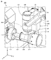
図1は、この発明の実施の形態における付加加工用ヘッドを備える加工機械を示す斜視図である。図1中には、加工機械の加工エリア内の様子が示されている。 FIG. 1 is a perspective view showing a processing machine including an additional processing head according to an embodiment of the present invention. FIG. 1 shows a state in the processing area of the processing machine.
図1を参照して、加工機械100は、ワークの付加加工(AM(Additive manufacturing)加工)と、ワークの除去加工(SM(Subtractive manufacturing)加工)とが可能なAM/SMハイブリッド加工機である。加工機械100は、SM加工の機能として、固定工具を用いた旋削機能と、回転工具を用いたミーリング機能とを有する。
Referring to FIG. 1, a
加工機械100の全体構造について説明すると、加工機械100は、第1主軸台111と、第2主軸台(不図示)と、工具主軸121と、下刃物台(不図示)とを有する。第1主軸台111、第2主軸台、工具主軸121および下刃物台は、スプラッシュガード206により囲われた加工エリア200内に設けられている。
The overall structure of the
第1主軸台111は、固定工具を用いた旋削加工時にワークを回転させるための主軸112を有する。主軸112は、水平方向に延びるZ軸に平行な中心軸201を中心に回転可能に設けられている。主軸112には、ワークを着脱可能に保持するためのチャック機構が設けられている。第2主軸台(不図示)は、第1主軸台111と同様の構造を有し、Z軸方向において第1主軸台111と対向して設けられている。
The
工具主軸(上刃物台)121は、回転工具を用いたミーリング加工時に回転工具を回転させる。工具主軸121は、鉛直方向に延びるX軸に平行な中心軸203を中心に回転可能に設けられている。工具主軸121には、回転工具を着脱可能に保持するためのクランプ機構が設けられている。
The tool spindle (upper tool rest) 121 rotates the rotary tool during milling using the rotary tool. The
工具主軸121は、図示しないコラム等によりベッド上に支持されている。工具主軸121は、コラム等に設けられた各種の送り機構や案内機構、サーボモータなどにより、X軸方向、水平方向に延び、Z軸方向に直交するY軸方向、およびZ軸方向に移動可能に設けられている。工具主軸121がX軸方向、Y軸方向およびZ軸方向に移動することによって、工具主軸121に装着された回転工具による加工位置は、3次元的に変位する。工具主軸121は、さらに、Y軸に平行な中心軸204を中心に旋回可能に設けられている。
The
下刃物台(不図示)は、旋削加工のための複数の固定工具を装着する。下刃物台は、いわゆるタレット形であり、複数の固定工具が放射状に取り付けられ、旋回割り出しを行なう。下刃物台は、図示しないサドル等によりベッド上に支持されている。下刃物台は、サドル等に設けられた各種の送り機構や案内機構、サーボモータなどにより、X軸方向およびZ軸方向に移動可能に設けられている。 A lower tool post (not shown) is equipped with a plurality of fixed tools for turning. The lower tool post has a so-called turret shape, and a plurality of fixed tools are attached in a radial manner to perform turning indexing. The lower tool rest is supported on the bed by a saddle or the like (not shown). The lower tool post is provided so as to be movable in the X-axis direction and the Z-axis direction by various feed mechanisms, guide mechanisms, servo motors, and the like provided in a saddle or the like.
加工機械100は、付加加工用ヘッド21を有する。付加加工用ヘッド21は、ワークに対して材料粉末を吐出するとともにエネルギー線を照射することにより付加加工を行なう(指向性エネルギー堆積法(Directed Energy Deposition))。エネルギー線としては、代表的に、レーザ光および電子ビームが挙げられる。本実施の形態では、付加加工にレーザ光が用いられる。
The
付加加工用ヘッド21は、工具主軸121に着脱可能に設けられている。付加加工時、付加加工用ヘッド21は、工具主軸121に装着される。工具主軸121が、X軸方向、Y軸方向およびZ軸方向に移動することによって、付加加工用ヘッド21による付加加工の加工位置が3次元的に変位する。さらに本実施の形態では、工具主軸121が中心軸204を中心に旋回することによって、付加加工用ヘッド21による付加加工の向き(ワークに対するレーザ光の照射方向)が変化する。除去加工時、付加加工用ヘッド21は、工具主軸121から離脱される。
The
なお、付加加工用ヘッド21を加工エリア200内で移動させるためのヘッド移動機構が、工具主軸121とは別に設けられてもよい。
In addition, a head moving mechanism for moving the
付加加工用ヘッド21は、ヘッド本体(本体部)22と、レーザツール(エネルギー線出射部)26と、ケーブル継手23とから構成されている。
The
ヘッド本体22には、レーザ光および材料粉末が導入される。付加加工用ヘッド21のうちヘッド本体22が、工具主軸121に着脱可能に設けられている。レーザツール26は、ワークに向けてレーザ光を出射するとともに、ワークにおけるレーザ光の照射領域を定める。
Laser light and material powder are introduced into the
なお、本実施の形態では、ワークにおけるレーザ光の照射領域を定める手段がレーザツール26に設けられる場合について説明するが、このような構成に限られず、レーザ光の照射領域を定める手段の全部または一部が、ヘッド本体22および/またはケーブル継手23に設けられてもよい。
In the present embodiment, the case where the
ケーブル継手23は、ケーブル24をヘッド本体22に接続するための継手として設けられている。ケーブル24は、加工エリア外に設置されたレーザ発振装置(不図示)から付加加工用ヘッド21に向けてレーザ光を導くための光ファイバと、加工エリア外に設置された材料粉末供給装置(不図示)から付加加工用ヘッド21に向けて材料粉末を導くための配管と、これらを収容する管部材とから構成されている。
The
なお、付加加工用ヘッド21を備える加工機械は、上記のAM/SMハイブリッド加工機械に限られない。たとえば、付加加工用ヘッド21を備える加工機械は、旋盤ベースのAM/SMハイブリッド加工機械であってもよいし、マシニングセンタベースのAM/SMハイブリッド加工機械であってもよい。マシニングセンタベースのAM/SMハイブリッド加工機械の場合、ワークを保持するワーク保持部としてテーブルが用いられる。また、付加加工用ヘッド21を備える加工機械は、付加加工のみ実行可能な加工機械であってもよい。
The processing machine including the
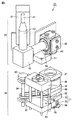
続いて、図1中の付加加工用ヘッドの構造についてより詳細に説明する。図2は、図1中の付加加工用ヘッドの内部構造を示す斜視図である。図3は、図1中の付加加工用ヘッドの内部構造を示す別の斜視図である。図中には、レーザツール26がヘッド本体22から分離された状態が示されている。
Next, the structure of the additional processing head in FIG. 1 will be described in more detail. FIG. 2 is a perspective view showing the internal structure of the additional processing head in FIG. FIG. 3 is another perspective view showing the internal structure of the additional processing head in FIG. In the drawing, the
図2および図3を参照して、まず、ヘッド本体22およびレーザツール26の連結機構について説明する。ヘッド本体22およびレーザツール26は、それぞれ、連結部51および連結部52を有する。連結部51および連結部52には、クランプ機構が内蔵されており、ヘッド本体22に対するレーザツール26の装着時、そのクランプ機構が作動することによって、連結部51および連結部52が互いに連結される。クランプ機構の一例として、バネ力によりクランプ状態を得て、油圧によりアンクランプ状態を得る機構が挙げられる。
With reference to FIG. 2 and FIG. 3, the connection mechanism of the head
次に、付加加工用ヘッド21においてワークに対してレーザ光を照射するための機構について説明する。ヘッド本体22は、光ファイバ41、レーザ光入射管42、レーザ光通路筐体43、レーザ光通路管44およびレーザ光通路筐体45を有する。
Next, a mechanism for irradiating the workpiece with laser light in the
光ファイバ41には、図1中のケーブル24からレーザ光が導かれる。光ファイバ41は、レーザ光入射管42に接続されている。レーザ光入射管42、レーザ光通路筐体43、レーザ光通路管44およびレーザ光通路筐体45は、挙げた順に連なって設けられている。レーザ光入射管42、レーザ光通路筐体43、レーザ光通路管44およびレーザ光通路筐体45は、ヘッド本体22におけるレーザ光の通路を形成している。
Laser light is guided to the
レーザツール26は、レーザ光通路筐体48およびレーザ光出射筐体49を有する。レーザ光通路筐体48およびレーザ光出射筐体49は、連なって設けられている。レーザ光通路筐体48およびレーザ光出射筐体49は、レーザツール26におけるレーザ光の通路を形成している。
The
ヘッド本体22およびレーザツール26は、それぞれ、接続部46および接続部47を有する。ヘッド本体22に対するレーザツール26の装着時、接続部46に接続部47が接続されることによって、ヘッド本体22およびレーザツール26間でレーザ光の通路が連通する。
The head
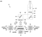
図4は、図1中の付加加工用ヘッドの光学系を模式的に表した図である。図2から図4を参照して、ヘッド本体22は、コリメーションレンズ61、反射鏡62、反射鏡63および保護ガラス64を有する。
FIG. 4 is a diagram schematically showing the optical system of the additional processing head in FIG. 2 to 4, the head
コリメーションレンズ61は、レーザ光入射管42に収容されている。コリメーションレンズ61は、光ファイバ41から入力されたレーザ光を平行光にして、反射鏡62および反射鏡63に向けて送る。反射鏡62および反射鏡63は、それぞれ、レーザ光通路筐体43およびレーザ光通路筐体45に収容されている。反射鏡62および反射鏡63は、コリメーションレンズ61からのレーザ光を反射させてレーザツール26に向けて送る。
The
保護ガラス64は、接続部46に設けられている。保護ガラス64は、ヘッド本体22に内蔵された光学部品を外部雰囲気から保護するために設けられている。
The
レーザツール26は、保護ガラス65、集光レンズ66および保護ガラス67を有する。集光レンズ66は、レーザ光通路筐体48に収容されている。集光レンズ66は、レーザ光をワーク上に集光するためのレンズであり、ワークにおけるレーザ光の照射領域を定める光学部品として設けられている。ワークにおけるレーザ光の照射領域を定める光学部品は、集光レンズ66に限られず、たとえば、ミラーであってもよい。
The
保護ガラス65および保護ガラス67は、それぞれ、接続部47およびレーザ光出射筐体49に設けられている。保護ガラス65および保護ガラス67は、レーザツール26に内蔵された光学部品を外部雰囲気から保護するために設けられている。
The
ヘッド本体22には、実行する付加加工の条件に合わせて、複数のレーザツール26(図4中では、レーザツール26A、レーザツール26Bおよびレーザツール26C)のうちいずれか1つのレーザツール26が選択的に装着される。複数のレーザツール26は、ワーク上に定められるレーザ光の照射領域の形状や大きさが互いに異なる。
For the
図4中に示す例でいえば、レーザツール26Aは、集光レンズ66Aを有し、この集光レンズ66Aによって、ワーク上に直径2mmの円形の照射領域を定める。レーザツール26Bは、ホモジナイザー68および集光レンズ66Bを有し、このホモジナイザー68および集光レンズ66Bによって、ワーク上に3mm×8mmの矩形の照射領域を定める。レーザツール26Cは、集光レンズ66Cを有し、この集光レンズ66Cによって、ワーク上に直径4mmの円形の照射領域を定める。
In the example shown in FIG. 4, the
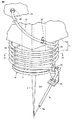
図5は、図1中の付加加工用ヘッドの先端部を示す斜視図である。図2から図5を参照して、次に、付加加工用ヘッド21においてワークに対して材料粉末を吐出するための機構について説明する。
FIG. 5 is a perspective view showing the tip of the additional processing head in FIG. Next, a mechanism for discharging material powder to the workpiece in the
レーザツール26は、固定部材71、回転部材76およびノズル78を有する(図2および図3中では、ノズル78の図示が省略されている)。
The
固定部材71は、レーザ光出射筐体49と隣り合って設けられている。固定部材71は、レーザ光出射筐体49に対して、レーザ光通路筐体48の反対側に設けられている。固定部材71は、レーザツール26を構成する他の部品に固定して設けられている。
The fixing
回転部材76は、中心軸221(図5を参照のこと)を中心に回転可能に設けられている。中心軸221は、レーザツール26からワークに向けて照射されるレーザ光311の光軸に沿った方向に延びる。本実施の形態では、中心軸221が、レーザ光311の光軸と重なる。回転部材76は、中心軸221の軸方向において、固定部材71と連設されている。すなわち、回転部材76および固定部材71は、中心軸221の軸方向において並んで設けられている。
The rotating
固定部材71には、中空部74が形成されている(図5を参照のこと)。回転部材76には、中空部77が形成されている(図3を参照のこと)。レーザ光311は、中空部74および中空部77を通り、レーザツール26からワークに向けて照射される。
The fixing
固定部材71および回転部材76の構造についてより具体的に説明すると、固定部材71は、基部72および円筒部73から構成されている。基部72は、レーザ光出射筐体49と隣り合って設けられている。円筒部73は、中空部74を備えた円筒形状を有する。円筒部73は、基部72からレーザ光311の光軸方向に沿って円筒状に延出するように設けられている。回転部材76は、基部72から円筒状に延出する円筒部73の先端に設けられている。回転部材76は、中空部77を備えた円板形状を有する。
More specifically, the structure of the fixing
ノズル78は、回転部材76に接続されている。ノズル78は、ワークに向けて材料粉末を吐出する。図1中のケーブル24から付加加工用ヘッド21に導かれた材料粉末は、後述するチューブ81を通じてノズル78に供給される。
The
ノズル78は、回転部材76からレーザ光311の光軸方向に沿って延出している。ノズル78は、中心軸221(レーザ光311の光軸)からその半径方向に離れた位置に設けられている。ノズル78は、回転部材76から延出する先端に、材料粉末を吐出する吐出口78jを有する。吐出口78jは、中心軸221(レーザ光311の光軸)からその半径方向に離れた位置で開口している。吐出口78jは、ワーク上に形成されるレーザ光311の照射領域(スポット)と対向して開口している。
The
ノズル78は、回転部材76が中心軸221を中心に回転するのに伴って、ワークに向けて照射されるレーザ光311の周りで周方向に移動する。特に本実施の形態では、回転部材76の回転中心である中心軸221が、レーザ光311の光軸と重なるため、ノズル78はレーザ光311の光軸を中心に回転移動する。
The
ヘッド本体22は、回転駆動源としてのサーボモータ31と、クラッチ板32とを有する。レーザツール26は、クラッチ板33と、回転シャフト34と、プーリベルト35とを有する。
The
クラッチ板32は、サーボモータ31の出力軸に接続されている。回転シャフト34は、クラッチ板33に接続されている。ヘッド本体22に対するレーザツール26の装着時、クラッチ板33がクラッチ板32に摩擦係合することにより、サーボモータ31から出力された回転が回転シャフト34に伝達される。プーリベルト35は、回転シャフト34および回転部材76に設けられたプーリ(不図示)間に掛け渡されている。回転シャフト34の回転がプーリベルト35を介して回転部材76に伝達されることによって、回転部材76が中心軸221を中心に回転する。
The
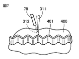
図6は、付加加工時のワーク表面を拡大して示す断面図である。図6を参照して、付加加工時、付加加工用ヘッド21が装着された工具主軸121の移動、および/または、ワーク400を保持する第1主軸台111の主軸112の回転によって(図1を参照のこと)、レーザツール26をワーク400に対向させつつ、付加加工用ヘッド21およびワーク400を相対的に移動させる。このとき、付加加工用ヘッド21(レーザツール26)からワーク400に向けて、レーザ光311と、材料粉末312と、シールドおよびキャリア用のガス313とが吐出される。これにより、ワーク400の表面に溶融点314が形成され、その結果、材料粉末312が溶着する。
FIG. 6 is an enlarged cross-sectional view of the workpiece surface during additional machining. Referring to FIG. 6, during the additional machining, the
具体的には、ワーク400の表面に肉盛層316が形成される。肉盛層316上には、肉盛素材315が盛られる。肉盛素材315が冷却されると、ワーク400の表面に加工可能な層が形成された状態となる。材料粉末としては、アルミニウム合金およびマグネシウム合金等の金属粉末や、セラミック粉末を利用することができる。
Specifically, the
本実施の形態における付加加工用ヘッド21においては、サーボモータ31の制御によって、ワークに対する付加加工用ヘッド21の相対移動方向を基準にして、材料粉末がノズル78からワークに向けて吐出される方向が一定となるように、ノズル78が回転駆動される。以下、そのような制御が行なわれる理由について説明する。
In the
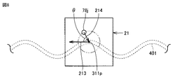
図7は、ワークに行なわれる付加加工の一例を示す斜視図である。図8は、図7中の付加加工において、ワークおよび付加加工用ヘッドの相対移動方向と、材料粉末の吐出方向との関係を示す図である。 FIG. 7 is a perspective view showing an example of additional processing performed on the workpiece. FIG. 8 is a diagram showing the relationship between the relative movement direction of the workpiece and the additional processing head and the discharge direction of the material powder in the additional processing in FIG.
図7および図8を参照して、付加加工用ヘッド21による付加加工により、ワーク400の表面上に波形状の肉盛層401を形成する場合が想定されている。この場合、ワーク400および付加加工用ヘッド21を波状に相対移動させながら、肉盛層401を積層してゆく。このとき、ワーク400および付加加工用ヘッド21の相対移動方向は、図8中の矢印213に示す方向となり、加工の進行とともに連続的に変化する。
With reference to FIGS. 7 and 8, it is assumed that a
材料粉末は、ノズル78の吐出口78jからワーク400上のレーザ光311のスポット311pに向けて吐出される。レーザ光311の光軸方向から見て、ワーク400に対する材料粉末の吐出方向は、図8中の矢印214に示す方向となる。この際、ワーク400および付加加工用ヘッド21の相対移動方向と、ワーク400に対する材料粉末の吐出方向との間には、ワーク400への材料粉末の付着効率が良好となる最適な角度関係が存在する。このような角度関係は、ワーク400および付加加工用ヘッド21の相対移動方向と、ワーク400に対する材料粉末の吐出方向との角度を変えながら、ワーク400への材料粉末の付着状況を調べることによって特定することができる。図中に示す付加加工の一例では、ワーク400および付加加工用ヘッド21の相対移動方向と、ワーク400に対する材料粉末の吐出方向とがなす角度がθである場合に、ワーク400への材料粉末の付着効率が最も良好となる(たとえば、ノズル78からの材料粉末の吐出量に対して70〜90%の割合)。
The material powder is discharged from the
本実施の形態における付加加工用ヘッド21においては、ワーク400および付加加工用ヘッド21の相対移動方向の変化にかかわらず、ワーク400および付加加工用ヘッド21の相対移動方向と、ワーク400に対する材料粉末の吐出方向とがなす角度がθに保たれるように、ノズル78がレーザ光311の周りで回転駆動される。
In the
これにより、付加加工の全体に渡ってワーク400への材料粉末の付着効率が良好となり、材料粉末の歩留まりを向上させることができる。また、ワーク400への材料粉末の付着効率にばらつきが生じないため、周方向において一定の厚みを備えた肉盛層401を形成することができる。
Thereby, the adhesion efficiency of the material powder to the workpiece | work 400 becomes favorable over the whole additional process, and the yield of material powder can be improved. Further, since there is no variation in the adhesion efficiency of the material powder to the
続いて、付加加工用ヘッド21におけるノズル78への材料粉末の供給機構について説明する。
Next, a mechanism for supplying material powder to the
図2、図3および図5を参照して、付加加工用ヘッド21に導かれた材料粉末は、ヘッド本体22から、レーザツール26における連結部52に導入される。レーザツール26は、チューブ81を有する。チューブ81は、連結部52およびノズル78の間に設けられている。チューブ81は、連結部52に導入された材料粉末をノズル78に向けて供給する。
With reference to FIGS. 2, 3, and 5, the material powder guided to the
本実施の形態では、チューブ81が、連結部52およびノズル78の間に着脱可能に設けられている。より具体的には、連結部52には、配管継手86が接続されている。ノズル78の端部(吐出口78jとは反対側の端部)には、配管継手85が接続されている。チューブ81の一方端が配管継手86を介して連結部52に接続され、チューブ81の他方端が配管継手85を介してノズル78に接続されている。
In the present embodiment, the
このような構成によれば、材料粉末の供給路を形成するチューブ81の内壁が摩耗した場合であっても、チューブ81を容易に交換することができる。これにより、付加加工用ヘッド21のメンテナンス性を向上させることができる。
According to such a configuration, even when the inner wall of the
チューブ81は、可撓性を有する。チューブ81は、たとえば、樹脂製のフレキシブルチューブである。チューブ81の内周面には、耐摩耗性を向上させるためのコーティング層が設けられてもよい。
The
チューブ81は、レーザ光311の周りで周回するように設けられている。チューブ81の周回中心軸は、レーザ光311の光軸に略一致する。チューブ81は、レーザ光311の周りで複数回、周回するように設けられている。図5中に示す例では、チューブ81は、レーザ光311の周りで5回、周回するように設けられている。チューブ81は、レーザ光311の光軸方向に沿って螺旋状に設けられている。すなわち、チューブ81は、レーザ光311の光軸方向にずれながらレーザ光311の周りを周回している。
The
チューブ81は、固定部材71(より具体的には、円筒部73)の周りで周回するように設けられている。チューブ81の周回中心軸は、回転部材76の回転中心である中心軸221に略一致する。
The
固定部材71(より具体的には、基部72)には、留め具82が取り付けられている。回転部材76には、留め具83が取り付けられている。チューブ81は、レーザ光311の周りで周回する区間の一方端にて、留め具82により固定部材71に支持され、レーザ光311の周りで周回する区間の他方端にて、留め具83により回転部材76に支持されている。
A
レーザツール26は、複数の保持ピン88を有する。複数の保持ピン88は、チューブ81をレーザ光311(円筒部73)の周りで周回する形態に保持するように構成されている。
The
より具体的には、保持ピン88は、ピン形状を有する。保持ピン88は、円筒部73の外周面から径方向外側に突出するように設けられている。複数の保持ピン88は、円筒部73におけるチューブ81の経路に沿って設けられている。すなわち、複数の保持ピン88は、中心軸221の軸方向に位置をずらしながら、中心軸221の周方向に所定間隔(本実施の形態では、90°間隔)を隔てて設けられている。チューブ81は、中心軸221の軸方向に隣り合う保持ピン88の間に位置決めされることにより、レーザ光311の周りで周回する形態に保持されている。
More specifically, the holding
なお、周方向において保持ピン88が設けられる間隔は、特に限定されず、たとえば、120°間隔であってもよいし、60°間隔であってもよい。周方向において保持ピン88が設けられる間隔は、等間隔であることが好ましい。チューブ81をレーザ光311の周りで周回する形態に保持する機構は、上記のピン構造に限られず、たとえば、円筒部73の外周面上において中心軸221を中心に螺旋状に延びるリブ構造であってもよい。
The interval at which the holding pins 88 are provided in the circumferential direction is not particularly limited, and may be, for example, 120 ° intervals or 60 ° intervals. The intervals at which the holding pins 88 are provided in the circumferential direction are preferably equal intervals. The mechanism for holding the
チューブ81は、直線状のチューブ材であってもよいし、予め螺旋状に成形されたチューブ材であってもよい。
The
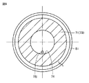
図9から図11は、図5中のIX−IX線上の矢視方向から見たレーザツールを示す断面図である。 9 to 11 are cross-sectional views showing the laser tool viewed from the direction of the arrow on the line IX-IX in FIG.
図5および図9から図11を参照して、本実施の形態では、回転部材76が、中心軸211を回転中心として±180°の範囲で回転する。図9中には、回転部材76が0°の位相位置にある時のノズル78の吐出口78jおよびチューブ81が示され、図10中には、回転部材76が+180°の位相位置にある時のノズル78の吐出口78jおよびチューブ81が示され、図11中には、回転部材76が−180°の位相位置にある時のノズル78の吐出口78jおよびチューブ81が示されている。
With reference to FIGS. 5 and 9 to 11, in the present embodiment, rotating
付加加工用ヘッド21においては、ノズル78の周方向における移動に伴って、材料粉末が導入される連結部52と、材料粉末を吐出するノズル78との間の相対的な位置関係が変化する。これに対して、レーザ光311の周りを周回するチューブ81が、ノズル78の移動方向に合わせて拡径方向または縮径方向に変形することによって、連結部52およびノズル78間の相対的な位置関係を吸収することができる。
In the
より具体的には、回転部材76が0°の位相位置にある時のチューブ81の周回径を基準にして、回転部材76が0°から+180°の位相位置に向けて回転する間、チューブ81は、その周回径が大きくなるように変形する(図9に示すチューブ81から図10に示すチューブ81への変形)。回転部材76が0°から−180°の位相位置に向けて回転する間、チューブ81は、その周回径が小さくなるように変形する(図9に示すチューブ81から図11に示すチューブ81への変形)。
More specifically, while the rotating
この際、チューブ81をレーザ光311の周りで複数回、周回させる構成によって、ノズル78の移動に伴うチューブ81の周回径の変化量を小さく抑えることができる。これにより、付加加工用ヘッド21をコンパクトに構成することができる。また、チューブ81は、レーザ光311の光軸方向に沿って螺旋状に設けられるため、特にレーザ光311の光軸に対する半径方向(中心軸211の半径方向)において、付加加工用ヘッド21をコンパクトに構成することができる。
At this time, the configuration in which the
さらに本実施の形態では、回転部材76が−180°の位相位置にある時、チューブ81が、固定部材71(円筒部73の外周面)に接触する。このような構成によれば、ノズル78の移動に伴って変化するチューブ81の周回径の最大値を小さく抑えることができる。
Further, in the present embodiment, when the rotating
なお、回転部材76の回転範囲は、上記の±180°に限られず、付加加工時におけるレーザ照射の軌跡などを考慮して適宜、設定してもよい。この際、回転部材76の回転範囲に合わせて、チューブ81の周回数や全長などを変更してもよい。
Note that the rotation range of the rotating
チューブ81の周回形態は、上記のレーザ光311の光軸方向に沿った螺旋状に限られず、たとえば、レーザ光311の光軸を中心とする渦巻き形状であってもよい。
The winding form of the
本発明が適用される付加加工法は、指向性エネルギー堆積法に限られず、たとえば、材料上に原料ガスを供給しながらレーザ光を照射するレーザCVD法であってもよい。 The additional processing method to which the present invention is applied is not limited to the directional energy deposition method, and may be, for example, a laser CVD method of irradiating a laser beam while supplying a raw material gas onto the material.
以上に説明した、この発明の実施の形態における付加加工用ヘッド21および加工機械100の構造を、本発明の構成と対応させて説明すると、本実施の形態における付加加工用ヘッド21は、ワークに対して材料としての材料粉末を吐出するとともにエネルギー線としてのレーザ光311を照射しながら相対移動可能な付加加工用ヘッドである。付加加工用ヘッド21は、材料粉末が導入される導入部としての連結部52と、ワークに向けて照射されるレーザ光311の周りで周方向に移動可能に設けられ、材料粉末を吐出するノズル78と、連結部52およびノズル78の間に設けられ、連結部52に導入された材料粉末をノズル78に向けて供給する管部材としてのチューブ81とを備える。チューブ81は、可撓性を有し、レーザ光311の周りで周回するように設けられる。
The structure of the
また、加工機械100は、ワークの除去加工および付加加工が可能な加工機械である。加工機械100は、付加加工用ヘッド21と、ワークを保持するワーク保持部としての第1主軸台111および第2主軸台と、ワークの除去加工のための工具を保持する工具保持部としての工具主軸121および下刃物台とを備える。
The
このように構成された、この発明の実施の形態における付加加工用ヘッド21および加工機械100によれば、周方向に移動するノズル78に材料粉末を供給する機構を、簡易な構成により実現するとともに、ノズル78の移動に伴ってワークへの材料粉末の供給量が変動することを抑制できる。
According to the
今回開示された実施の形態はすべての点で例示であって制限的なものではないと考えられるべきである。本発明の範囲は上記した説明ではなくて特許請求の範囲によって示され、特許請求の範囲と均等の意味および範囲内でのすべての変更が含まれることが意図される。 The embodiment disclosed this time should be considered as illustrative in all points and not restrictive. The scope of the present invention is defined by the terms of the claims, rather than the description above, and is intended to include any modifications within the scope and meaning equivalent to the terms of the claims.
この発明は、たとえば、指向性エネルギー堆積法による付加加工を実行するための付加加工用ヘッドに適用される。 The present invention is applied to, for example, an additional processing head for performing additional processing by a directional energy deposition method.
21 付加加工用ヘッド、22 ヘッド本体、23 ケーブル継手、24 ケーブル、26,26A,26B,26C レーザツール、31 サーボモータ、32,33 クラッチ板、34 回転シャフト、35 プーリベルト、41 光ファイバ、42 レーザ光入射管、43,45,48 レーザ光通路筐体、44 レーザ光通路管、46,47 接続部、49 レーザ光出射筐体、51,52 連結部、61 コリメーションレンズ、62,63 反射鏡、64,65,67 保護ガラス、66,66A,66B,66C 集光レンズ、68 ホモジナイザー、71 固定部材、72 基部、73 円筒部、74,77 中空部、76 回転部材、78 ノズル、78j 吐出口、81 チューブ、82,83 留め具、85,86 配管継手、88 保持ピン、100 加工機械、111 第1主軸台、112 主軸、121 工具主軸、201,203,204,211,221 中心軸、206 スプラッシュガード、311 レーザ光、311p スポット、312 材料粉末、313 ガス、314 溶融点、315 肉盛素材、316,401 肉盛層、400 ワーク。 21 Head for additional processing, 22 Head body, 23 Cable joint, 24 Cable, 26, 26A, 26B, 26C Laser tool, 31 Servo motor, 32, 33 Clutch plate, 34 Rotating shaft, 35 Pulley belt, 41 Optical fiber, 42 Laser light incident tube, 43, 45, 48 Laser light passage housing, 44 Laser light passage tube, 46, 47 connection portion, 49 Laser light emission housing, 51, 52 connection portion, 61 Collimation lens, 62, 63 Reflector , 64, 65, 67 Protective glass, 66, 66A, 66B, 66C Condensing lens, 68 Homogenizer, 71 Fixed member, 72 Base part, 73 Cylindrical part, 74, 77 Hollow part, 76 Rotating member, 78 Nozzle, 78j Discharge port , 81 Tube, 82, 83 Fastener, 85, 86 Piping joint, 88 Holding pin , 100 processing machine, 111 first spindle stock, 112 spindle, 121 tool spindle, 201, 203, 204, 211, 221 central axis, 206 splash guard, 311 laser beam, 311p spot, 312 material powder, 313 gas, 314 Melting point, 315 overlay material, 316, 401 overlay layer, 400 workpieces.
Claims (8)
材料が導入される導入部と、
ワークに向けて照射されるエネルギー線の周りで周方向に移動可能に設けられ、材料を吐出するノズルと、
前記導入部および前記ノズルの間に設けられ、前記導入部に導入された材料を前記ノズルに向けて供給する管部材とを備え、
前記管部材は、可撓性を有し、エネルギー線の周りで周回するように設けられる、付加加工用ヘッド。 It is an additional processing head that can move relative to the workpiece while discharging the material and irradiating energy rays,
An introduction where the material is introduced;
A nozzle that is provided so as to be movable in the circumferential direction around the energy rays irradiated toward the workpiece, and that discharges the material;
A pipe member provided between the introduction part and the nozzle and supplying the material introduced into the introduction part toward the nozzle;
The tube member is a head for additional processing that has flexibility and is provided so as to circulate around an energy ray.
エネルギー線が通される中空部を有し、前記回転部材の回転軸方向において前記回転部材と連設される固定部材とをさらに備え、
前記管部材は、前記固定部材の周りで周回するように設けられ、
前記回転部材が0°の位相位置にある時の前記管部材の周回径を基準にして、前記回転部材が0°から+A°の位相位置に向けて回転する間、前記管部材は、その周回径が大きくなるように変形し、前記回転部材が0°から−A°の位相位置に向けて回転する間、前記管部材は、その周回径が小さくなるように変形する、請求項1から5のいずれか1項に記載の付加加工用ヘッド。 A rotating member that rotates in a range of ± A ° so that the nozzle is connected and the nozzle is moved in the circumferential direction around the energy line;
A hollow member through which an energy beam passes, and a fixing member provided continuously with the rotating member in a rotating shaft direction of the rotating member,
The tube member is provided to circulate around the fixed member,
While the rotating member rotates from 0 ° to a phase position of + A ° with respect to the circumference of the tube member when the rotating member is at the 0 ° phase position, the tube member 6. The pipe member is deformed so that a circular diameter thereof is reduced while the diameter of the tube member is increased so that the rotating member rotates toward a phase position of 0 ° to −A °. The additional processing head according to any one of the above.
請求項1から7のいずれか1項に記載の付加加工用ヘッドと、
ワークを保持するワーク保持部と、
ワークの除去加工のための工具を保持する工具保持部とを備える、加工機械。 A processing machine capable of removing and adding workpieces,
A head for additional processing according to any one of claims 1 to 7,
A work holding unit for holding a work;
A processing machine comprising a tool holding unit that holds a tool for workpiece removal processing.
Priority Applications (1)
| Application Number | Priority Date | Filing Date | Title |
|---|---|---|---|
| JP2016158402A JP6783092B2 (en) | 2016-08-12 | 2016-08-12 | Additional machining heads and machining machines |
Applications Claiming Priority (1)
| Application Number | Priority Date | Filing Date | Title |
|---|---|---|---|
| JP2016158402A JP6783092B2 (en) | 2016-08-12 | 2016-08-12 | Additional machining heads and machining machines |
Publications (2)
| Publication Number | Publication Date |
|---|---|
| JP2018024006A true JP2018024006A (en) | 2018-02-15 |
| JP6783092B2 JP6783092B2 (en) | 2020-11-11 |
Family
ID=61193516
Family Applications (1)
| Application Number | Title | Priority Date | Filing Date |
|---|---|---|---|
| JP2016158402A Active JP6783092B2 (en) | 2016-08-12 | 2016-08-12 | Additional machining heads and machining machines |
Country Status (1)
| Country | Link |
|---|---|
| JP (1) | JP6783092B2 (en) |
Cited By (5)
| Publication number | Priority date | Publication date | Assignee | Title |
|---|---|---|---|---|
| JP2021079413A (en) * | 2019-11-20 | 2021-05-27 | Dmg森精機株式会社 | Working machine |
| CN113199213A (en) * | 2021-04-30 | 2021-08-03 | 西安煤矿机械有限公司 | Manufacturing process of wear-resistant and corrosion-resistant central water pipe of rocker arm of coal mining machine |
| JPWO2021215003A1 (en) * | 2020-04-24 | 2021-10-28 | ||
| CN114453757A (en) * | 2022-02-18 | 2022-05-10 | 上饶市兴杰达光电科技有限公司 | Wide-angle optical lens surface laser processing equipment |
| DE102023107076A1 (en) * | 2023-03-21 | 2024-09-26 | TRUMPF Laser- und Systemtechnik SE | Laser spindle with a helix carrier |
Citations (3)
| Publication number | Priority date | Publication date | Assignee | Title |
|---|---|---|---|---|
| JPH03198994A (en) * | 1989-12-27 | 1991-08-30 | Gebr Sulzer Ag | Welding and/or coating device for work, nozzle for such device and manipulator for nozzle of such device |
| JP2004090135A (en) * | 2002-08-30 | 2004-03-25 | Denso Wave Inc | Joint structure of robot |
| JP5947941B1 (en) * | 2015-03-26 | 2016-07-06 | Dmg森精機株式会社 | Additional processing head and processing machine |
-
2016
- 2016-08-12 JP JP2016158402A patent/JP6783092B2/en active Active
Patent Citations (3)
| Publication number | Priority date | Publication date | Assignee | Title |
|---|---|---|---|---|
| JPH03198994A (en) * | 1989-12-27 | 1991-08-30 | Gebr Sulzer Ag | Welding and/or coating device for work, nozzle for such device and manipulator for nozzle of such device |
| JP2004090135A (en) * | 2002-08-30 | 2004-03-25 | Denso Wave Inc | Joint structure of robot |
| JP5947941B1 (en) * | 2015-03-26 | 2016-07-06 | Dmg森精機株式会社 | Additional processing head and processing machine |
Cited By (7)
| Publication number | Priority date | Publication date | Assignee | Title |
|---|---|---|---|---|
| JP2021079413A (en) * | 2019-11-20 | 2021-05-27 | Dmg森精機株式会社 | Working machine |
| JPWO2021215003A1 (en) * | 2020-04-24 | 2021-10-28 | ||
| WO2021215003A1 (en) * | 2020-04-24 | 2021-10-28 | Dmg森精機株式会社 | Clamp device and processing machine |
| EP4141267A4 (en) * | 2020-04-24 | 2023-06-14 | DMG Mori Co., Ltd. | CLAMPING DEVICE AND PROCESSING MACHINE |
| CN113199213A (en) * | 2021-04-30 | 2021-08-03 | 西安煤矿机械有限公司 | Manufacturing process of wear-resistant and corrosion-resistant central water pipe of rocker arm of coal mining machine |
| CN114453757A (en) * | 2022-02-18 | 2022-05-10 | 上饶市兴杰达光电科技有限公司 | Wide-angle optical lens surface laser processing equipment |
| DE102023107076A1 (en) * | 2023-03-21 | 2024-09-26 | TRUMPF Laser- und Systemtechnik SE | Laser spindle with a helix carrier |
Also Published As
| Publication number | Publication date |
|---|---|
| JP6783092B2 (en) | 2020-11-11 |
Similar Documents
| Publication | Publication Date | Title |
|---|---|---|
| JP5947941B1 (en) | Additional processing head and processing machine | |
| JP6535821B2 (en) | Additional processing head and processing machine | |
| CN107735209B (en) | Processing machine | |
| JP6529610B2 (en) | Additional processing head and processing machine | |
| JP5937249B1 (en) | Processing machine | |
| JP2018024006A (en) | Additional processing head and processing machine | |
| JP6785055B2 (en) | Processing machine | |
| JP6850934B1 (en) | Processing machine | |
| WO2018168197A1 (en) | Turret tool post | |
| CN115768588B (en) | Workpiece processing method and machine tool | |
| JP6983856B2 (en) | Processing machine | |
| JP7527484B2 (en) | Processing Machinery | |
| JP2011230161A (en) | Mechanism for guiding workpiece, and laser beam machining apparatus having the guide mechanism | |
| JP2018065193A (en) | NC lathe | |
| JPH0760472A (en) | Turret base of laser beam machine |
Legal Events
| Date | Code | Title | Description |
|---|---|---|---|
| A621 | Written request for application examination |
Free format text: JAPANESE INTERMEDIATE CODE: A621 Effective date: 20190314 |
|
| A977 | Report on retrieval |
Free format text: JAPANESE INTERMEDIATE CODE: A971007 Effective date: 20200219 |
|
| A131 | Notification of reasons for refusal |
Free format text: JAPANESE INTERMEDIATE CODE: A131 Effective date: 20200303 |
|
| A521 | Request for written amendment filed |
Free format text: JAPANESE INTERMEDIATE CODE: A523 Effective date: 20200427 |
|
| TRDD | Decision of grant or rejection written | ||
| A01 | Written decision to grant a patent or to grant a registration (utility model) |
Free format text: JAPANESE INTERMEDIATE CODE: A01 Effective date: 20200929 |
|
| A61 | First payment of annual fees (during grant procedure) |
Free format text: JAPANESE INTERMEDIATE CODE: A61 Effective date: 20201021 |
|
| R150 | Certificate of patent or registration of utility model |
Ref document number: 6783092 Country of ref document: JP Free format text: JAPANESE INTERMEDIATE CODE: R150 |
|
| R250 | Receipt of annual fees |
Free format text: JAPANESE INTERMEDIATE CODE: R250 |