JP2018024063A - Spindle device of machine tool - Google Patents
Spindle device of machine tool Download PDFInfo
- Publication number
- JP2018024063A JP2018024063A JP2016157968A JP2016157968A JP2018024063A JP 2018024063 A JP2018024063 A JP 2018024063A JP 2016157968 A JP2016157968 A JP 2016157968A JP 2016157968 A JP2016157968 A JP 2016157968A JP 2018024063 A JP2018024063 A JP 2018024063A
- Authority
- JP
- Japan
- Prior art keywords
- vibration
- spindle
- main shaft
- damping
- damping member
- Prior art date
- Legal status (The legal status is an assumption and is not a legal conclusion. Google has not performed a legal analysis and makes no representation as to the accuracy of the status listed.)
- Granted
Links
Images
Landscapes
- Auxiliary Devices For Machine Tools (AREA)
- Turning (AREA)
Abstract
【課題】加工条件の変更を伴うことなく効果的な振動抑制を行う。【解決手段】主軸装置1は、工具が着脱可能で、ハウジング内で軸受4,4を介して回転可能に支持される主軸2と、主軸2を回転させるモータ3と、モータ3を制御する制御装置22とを含んでなり、さらに、主軸2内に設けられ、主軸2の回転軸方向で前後移動可能な制振カラー15と、主軸2の回転速度及び工具の寸法を含む加工条件と、軸受4の支持剛性及び減衰係数を含む軸受特性とに基づいて主軸2の振動形態を解析する演算装置24と、演算装置24の解析結果に基づいて制振カラー15を回転軸方向の初期位置へ移動させる移動手段(皿バネ16、加圧室17、圧油供給路18、制御弁20、油圧ユニット21、NC装置26)とを備える。【選択図】図1An object of the present invention is to effectively suppress vibration without changing machining conditions. A spindle device (1) includes a spindle (2) to which a tool is detachable, a spindle (2) rotatably supported in a housing via bearings (4, 4), a motor (3) for rotating the spindle (2), and a controller for controlling the motor (3). a vibration damping collar 15 provided in the spindle 2 and movable back and forth in the direction of the rotation axis of the spindle 2; machining conditions including the rotation speed of the spindle 2 and dimensions of the tool; and bearings. A calculation device 24 that analyzes the vibration mode of the main shaft 2 based on the bearing characteristics including the support stiffness and damping coefficient of 4, and moves the damping collar 15 to the initial position in the rotation axis direction based on the analysis result of the calculation device 24 moving means (disc spring 16, pressure chamber 17, pressure oil supply path 18, control valve 20, hydraulic unit 21, NC device 26). [Selection drawing] Fig. 1
Description
本発明は、加工中に発生する振動を抑制することができる工作機械の主軸装置に関する。 The present invention relates to a spindle device of a machine tool that can suppress vibrations generated during machining.
工具又はワークを回転させながら加工を行う工作機械においては、加工中にいわゆるびびり振動が発生して、加工面の仕上げ精度の悪化、工具摩耗、工具欠損といった問題が生じる。このようなびびり振動を抑制する方法として、例えば特許文献1には、振動センサ等によって検出された時間領域の振動に基づいて、びびり振動の発生を検出すると、k値及び位相情報を用いて最適回転速度を算出すると共に、位相情報からびびり振動の種類を特定し、過去に特定したびびり振動と異なるびびり振動が発生した場合には、k値を変更して最適回転速度を算出し直す発明が開示されている。また、特許文献2には、主軸を支持するハウジングに、ハウジングと主軸との隙間に油を周方向の三箇所以上から供給する機構を設け、変位センサにより検出された主軸の径方向の振動方向に応じて油圧及び油量を変更することで主軸の振動を抑制する発明が開示されている。
In a machine tool that performs processing while rotating a tool or a workpiece, so-called chatter vibration is generated during the processing, and problems such as deterioration of finishing accuracy of the processed surface, tool wear, and tool chipping occur. As a method for suppressing such chatter vibration, for example, in Patent Document 1, when occurrence of chatter vibration is detected based on vibration in a time domain detected by a vibration sensor or the like, it is optimal to use k value and phase information. An invention that calculates the rotational speed, specifies the type of chatter vibration from the phase information, and changes chatter vibration that is different from chatter vibration specified in the past, and recalculates the optimal rotational speed by changing the k value. It is disclosed. Further, in
特許文献1の発明においては、振動抑制に回転速度等の加工条件の変更を伴うため、加工精度の低下や加工時間の延長に繋がるおそれがある。特許文献2の発明においては、油圧供給の方向が一定で変更できないため、発生した振動によっては効果的な減衰が行えない場合がある。
In the invention of Patent Literature 1, since vibration suppression involves a change in processing conditions such as rotational speed, there is a risk that processing accuracy may be reduced and processing time may be extended. In the invention of
そこで、本発明は、加工条件の変更を伴うことなく効果的な振動抑制を行うことができる工作機械の主軸装置を提供することを目的としたものである。 Therefore, an object of the present invention is to provide a spindle device for a machine tool that can effectively suppress vibration without changing machining conditions.
上記目的を達成するために、請求項1に記載の発明は、工具が着脱可能で、ハウジング内で軸受を介して回転可能に支持される主軸と、前記主軸を回転させるモータと、前記モータを制御する制御装置とを含んでなる工作機械の主軸装置であって、
前記主軸内に設けられ、前記主軸の回転軸方向で前後移動可能な制振部材と、前記主軸の回転速度及び前記工具の寸法を含む加工条件と、前記軸受の支持剛性及び減衰係数を含む軸受特性とに基づいて前記主軸の振動形態を解析する振動解析手段と、前記振動解析手段の解析結果に基づいて前記制振部材を前記回転軸方向での所定位置へ移動させる移動手段とを備えることを特徴とする。
請求項2に記載の発明は、請求項1の構成において、加工中に前記主軸に発生した振動を検知する振動検知手段をさらに備え、前記振動解析手段は、前記振動検知手段によって検知された加工中の振動を解析し、前記移動手段は、前記振動解析手段の解析結果に基づいて前記制振部材を前記所定位置と異なる位置へ移動させることを特徴とする。
請求項3に記載の発明は、請求項1又は2の構成において、前記制振部材は、前記主軸内に形成された中空部内へ前後移動可能に収容され、前記移動手段は、前記中空部内に設けられ、前記制振部材を前後何れか一方側へ付勢する付勢手段と、前記制振部材を挟んで前記付勢手段の反対側に形成され、流体が供給される加圧室と、前記加圧室への流体圧を調整可能な流体圧調整機構とを含んでなることを特徴とする。
In order to achieve the above-mentioned object, the invention according to claim 1 is characterized in that a tool is detachable and is supported rotatably in a housing via a bearing, a motor for rotating the spindle, and the motor. A spindle device of a machine tool comprising a control device for controlling,
A vibration damping member provided in the main shaft and capable of moving back and forth in the direction of the rotation axis of the main shaft, a machining condition including a rotation speed of the main shaft and dimensions of the tool, a bearing including a support rigidity and a damping coefficient of the bearing. Vibration analyzing means for analyzing the vibration form of the main shaft based on characteristics, and moving means for moving the damping member to a predetermined position in the rotation axis direction based on the analysis result of the vibration analyzing means. It is characterized by.
According to a second aspect of the present invention, in the configuration of the first aspect, the apparatus further includes vibration detection means for detecting vibration generated in the main shaft during machining, and the vibration analysis means is the machining detected by the vibration detection means. The vibration means is analyzed, and the moving means moves the damping member to a position different from the predetermined position based on the analysis result of the vibration analyzing means.
According to a third aspect of the present invention, in the configuration of the first or second aspect, the damping member is accommodated in a hollow portion formed in the main shaft so as to be movable back and forth, and the moving means is disposed in the hollow portion. An urging means for urging the damping member to either one of the front and rear sides, a pressurizing chamber formed on the opposite side of the urging means across the damping member, and supplied with fluid; And a fluid pressure adjusting mechanism capable of adjusting a fluid pressure to the pressurizing chamber.
本発明によれば、加工条件と軸受特性とに基づいて主軸の振動形態を解析し、その解析結果に基づいて制振部材を所定位置へ移動させるので、加工条件を変更することなく、制振部材による減衰効果を発揮させて効果的な振動抑制を行うことができる。
特に、加工中に発生した振動を解析し、その解析結果に基づいて制振部材を所定位置と異なる位置へ移動させることで、加工中に主軸の固有振動数を変動させ続けて振動を効果的に抑制することができる。
According to the present invention, the vibration form of the main shaft is analyzed based on the machining conditions and the bearing characteristics, and the vibration damping member is moved to a predetermined position based on the analysis result, so that the vibration damping is not changed without changing the machining conditions. The damping effect by the member can be exhibited and effective vibration suppression can be performed.
In particular, the vibration generated during machining is analyzed, and the vibration control member is moved to a position different from the predetermined position based on the analysis result, so that the natural frequency of the main shaft can be continuously varied during machining, and the vibration can be effectively performed. Can be suppressed.
以下、本発明の実施の形態を図面に基づいて説明する。
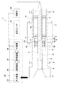
図1は、マシニングセンタ等の工作機械に設けられる主軸装置の一例を示す説明図である。この主軸装置1において、2は主軸で、モータ3によって図示しないハウジング内で軸受4,4を介して回転可能に支持される。この主軸2は中空となっており、軸心にはドローバー5が、進退動可能且つ主軸2内の後部に設けられた皿バネ7,7・・を用いた押圧機構6によって後退位置に付勢された状態で設けられている。このドローバー5は、後退位置で主軸2の前部に設けたチャック機構8をクランプ動作させて主軸2先端で工具ホルダ9をクランプするもので、図示しない油圧機構によって前進することでチャック機構8をアンクランプ動作させる。10は、ドローバー5の軸心に設けられた冷却液供給路である。
Hereinafter, embodiments of the present invention will be described with reference to the drawings.
FIG. 1 is an explanatory diagram showing an example of a spindle device provided in a machine tool such as a machining center. In this spindle device 1,
また、主軸2内で押圧機構6の前側には、押圧機構6の前端に位置する仕切板11で仕切られる中空部12が同軸で形成されて、その中空部12内に、制振機構13が設けられている。この制振機構13は、ドローバー5が貫通して中空部12の前端に固定される固定カラー14と、その後方でドローバー5が貫通して軸方向へ移動自在な制振部材としての制振カラー15と、固定カラー14と制振カラー15との間に介在されて制振カラー15を後方へ付勢する付勢手段としての複数の皿バネ16,16・・と、制振カラー15の後方で仕切板11との間に形成される加圧室17とからなる。冷却液供給路10の外側でドローバー5内には、ドローバー5の前後ストロークの範囲に亘って前端が加圧室17と連通する圧油供給路18が形成されている。
制振カラー15は、円筒形状の鋼材からなり、内周及び外周には、リング状の溝が形成されて、各溝に樹脂製のシール部材19,19が組み込まれて、加圧室17をシールしている。
Further, a
The damping
圧油供給路18は、制御弁20を介して油圧ユニット21に接続されており、油圧ユニット21から送られる圧油が圧油供給路18を介して加圧室17に供給される。よって、皿バネ16,16・・による付勢力と、加圧室17からの油圧とがバランスする位置で制振カラー15の前後位置が決定される。そして、加圧室17からの油圧の変更により、制振カラー15を軸方向へ前後移動させることで、主軸2の曲げ剛性と減衰特性とを変更可能となっている。
The pressure
次に、主軸装置1の制御系について説明する。
22は制御装置で、ここには入力装置23と、演算装置24と、記憶装置25と、NC装置26とが設けられている。
入力装置23は、オペレータによって主軸2の回転速度や工具寸法等の加工条件が入力可能であると共に、ハウジングに設けた図示しない振動センサ等の振動検知手段からの振動検知信号が入力可能となっている。
振動解析手段としての演算装置24は、入力装置23から入力される回転速度と工具寸法とを含む加工条件及び、記憶装置25に記録された後述する解析用データに基づいて主軸2の振動形態を解析し、解析した振動形態と皿バネ16のばね定数とから、制振カラー15を最大限に減衰効果を発揮する位置に移動させるための加圧室17への油圧を決定する。また、振動センサからの振動を解析してびびり振動の発生の有無も判定する。
Next, the control system of the spindle device 1 will be described.
The
The
記憶装置25は、主軸2の形状、軸受4の支持剛性及び減衰係数を含む軸受特性、皿バネ16のばね定数等からなる解析用データを予め記憶すると共に、演算装置24で決定された油圧を記憶する。併せて加工プログラムも記憶する。
NC装置26は、記憶装置25に記憶された加工プログラムに従ってモータ3等の制御を行うと共に、加圧室17が記憶装置25に記憶された油圧となるように制御弁20を制御する。ここでは圧油供給路18、制御弁20、油圧ユニット21、NC装置26が本発明の流体圧調整機構となり、これに皿バネ16を含めた構成が制振カラー15の移動手段となっている。
The
The NC
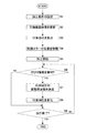
以上の如く構成された主軸装置1において、制御装置22は、上述した解析用データに基づいて主軸2の振動形態を解析し、解析した振動形態と皿バネ16のばね定数とから、制振カラー15を移動させて制振効果を発揮させる位置制御を実行する。以下、制振カラー15の位置制御を、図2のフローチャートに基づいて説明する。
まず、S1で、入力装置23により、主軸2の回転速度と工具寸法とが入力されて加工条件が設定される。
次に、S2で、演算装置24が、入力装置23から入力される加工条件と、記憶装置25に記憶された解析用データとに基づいて主軸2の振動形態を解析して記憶装置25へ記憶する。
In the spindle device 1 configured as described above, the
First, in S1, the rotational speed of the
Next, in S <b> 2, the
次に、S3で、解析した振動形態と皿バネ16のばね定数とから、制振カラー15を最大限に減衰効果を発揮する位置に移動させるための加圧室17へ付加する油圧を算出し、記憶装置25へ記憶する。
そして、S4で、NC装置26が、記憶装置25に記憶された油圧となるように制御弁20へ指令を送り、制振カラー15を初期位置へ移動させる。この初期位置は、解析された振動の最大振幅の腹の位置となっている。
Next, in S3, the hydraulic pressure applied to the pressurizing
Then, in S4, the
こうして制振カラー15を初期位置へ移動させた後、S5で加工を開始する。
加工中にS6でびびり振動を検知すると、S7で、演算装置24が、振動検知手段から得られる主軸2の振動や付加情報等をFFT解析してびびり周波数を特定した後、以下の式(1)に示すように、特定したびびり周波数fchatterに任意の係数αを乗算することで、制振カラー15に付加する油圧の変動周波数fcolorを決定する。
fcolor=α・fchatter ・・(1)
次に、S8で、演算装置24から付加油圧の変動周波数を得たNC装置26が、変動周波数に基づいて制御弁20を制御して付加する油圧を変化させ、制振カラー15を初期位置から前後何れかへスライドさせる。
この制振カラー15の移動によって振動形態が変化するため、初期位置で発生したびびり振動が抑制されることになる。
After moving the damping
When chatter vibration is detected in S6 during machining, the
f color = α · f chatter (1)
Next, in S8, the
Since the vibration form is changed by the movement of the damping
その後、S9で加工終了が確認されると位置制御は終了する。加工終了でない場合はS6へ戻ってびびり振動の検知を判別し、検知したら再びS7で付加油圧の振動周波数を決定してS8で付加油圧を変化させ、制振カラー15を直前の位置から前後何れかへスライドさせる。なお、S6でびびり振動を検知しない場合は、S9で加工終了を確認し、ここで加工終了でない場合はS6へ戻って再びびびり振動の検知を判別する。加工終了であれば位置制御を終了する。
Thereafter, when it is confirmed in S9 that the machining has been completed, the position control is terminated. If the machining is not finished, the process returns to S6 to determine the detection of chatter vibration, and if it is detected, the vibration frequency of the additional hydraulic pressure is determined again in S7, the additional hydraulic pressure is changed in S8, and the damping
このように、上記形態の工作機械の主軸装置1によれば、主軸2内に設けられ、主軸2の回転軸方向で前後移動可能な制振カラー15と、主軸2の回転速度及び工具の寸法を含む加工条件と、軸受4の支持剛性及び減衰係数を含む軸受特性とに基づいて主軸2の振動形態を解析する演算装置24と、演算装置24の解析結果に基づいて制振カラー15を回転軸方向での所定位置(初期位置)へ移動させる移動手段(皿バネ16、加圧室17、圧油供給路18、制御弁20、油圧ユニット21、NC装置26)とを備えることで、加工条件を変更することなく、制振カラー15による減衰効果を発揮させて効果的な振動抑制を行うことができる。
Thus, according to the spindle device 1 of the machine tool of the above embodiment, the damping
特にここでは、加工中に発生したびびり振動を演算装置24で解析し、その解析結果に基づいて制振カラー15を初期位置と異なる位置へ移動させるので、加工中に主軸2の固有振動数を変動させ続けてびびり振動を効果的に抑制することができる。
In particular, here, chatter vibration generated during machining is analyzed by the
なお、上記形態では、付勢手段である皿バネ16を前側に、加圧室17を後側に配置しているが、前後逆にしてもよい。付勢手段としては皿バネ以外にコイルバネ等も使用できる。また、加圧室へ供給する流体は油に限らず、空気やガス等の他の流体を使用してもよいし、加圧室への流体の供給路もドローバーに限らず、主軸に設けてもよい。
制振部材も上記形態の制振カラーに限らず、鋼材以外の金属を使用したり、複数の金属を組み合わせたりする変更は可能である。また、ドローバーが貫通するリング状でなく、ドローバーの周囲で同心円上に、球体等の制振部材を主軸の軸方向へ前後移動可能に収容した複数の中空部を設けて、各中空部ごとに付勢手段と加圧室とを設けて制振部材の位置制御を行うことも可能である。
In addition, in the said form, although the
The damping member is not limited to the damping collar of the above-described form, and can be changed by using a metal other than steel or combining a plurality of metals. Also, a plurality of hollow portions are provided in a concentric circle around the draw bar so that the draw bar penetrates, and a damping member such as a sphere can be moved back and forth in the axial direction of the main shaft. It is also possible to provide a biasing means and a pressurizing chamber to control the position of the damping member.
1・・主軸装置、2・・主軸、3・・モータ、4・・軸受、5・・ドローバー、6・・押圧機構、7,16・・皿バネ、12・・中空部、13・・制振機構、14・・固定カラー、15・・制振カラー、17・・加圧室、18・・圧油供給路、19・・シール部材、20・・制御弁、21・・油圧ユニット、22・・制御装置、23・・入力装置、24・・演算装置、25・・記憶装置、26・・NC装置。
1 ....
Claims (3)
前記主軸内に設けられ、前記主軸の回転軸方向で前後移動可能な制振部材と、
前記主軸の回転速度及び前記工具の寸法を含む加工条件と、前記軸受の支持剛性及び減衰係数を含む軸受特性とに基づいて前記主軸の振動形態を解析する振動解析手段と、
前記振動解析手段の解析結果に基づいて前記制振部材を前記回転軸方向での所定位置へ移動させる移動手段とを備えることを特徴とする工作機械の主軸装置。 A spindle device for a machine tool, comprising: a spindle that is attachable and detachable and rotatably supported via a bearing in a housing; a motor that rotates the spindle; and a control device that controls the motor. ,
A damping member provided in the main shaft and movable back and forth in the direction of the rotation axis of the main shaft;
Vibration analysis means for analyzing the vibration form of the spindle based on machining conditions including the rotation speed of the spindle and the dimensions of the tool, and bearing characteristics including support rigidity and damping coefficient of the bearing;
A spindle device for a machine tool, comprising: moving means for moving the damping member to a predetermined position in the direction of the rotation axis based on an analysis result of the vibration analysis means.
Priority Applications (1)
| Application Number | Priority Date | Filing Date | Title |
|---|---|---|---|
| JP2016157968A JP6726565B2 (en) | 2016-08-10 | 2016-08-10 | Machine tool spindle device |
Applications Claiming Priority (1)
| Application Number | Priority Date | Filing Date | Title |
|---|---|---|---|
| JP2016157968A JP6726565B2 (en) | 2016-08-10 | 2016-08-10 | Machine tool spindle device |
Publications (2)
| Publication Number | Publication Date |
|---|---|
| JP2018024063A true JP2018024063A (en) | 2018-02-15 |
| JP6726565B2 JP6726565B2 (en) | 2020-07-22 |
Family
ID=61193570
Family Applications (1)
| Application Number | Title | Priority Date | Filing Date |
|---|---|---|---|
| JP2016157968A Active JP6726565B2 (en) | 2016-08-10 | 2016-08-10 | Machine tool spindle device |
Country Status (1)
| Country | Link |
|---|---|
| JP (1) | JP6726565B2 (en) |
Cited By (1)
| Publication number | Priority date | Publication date | Assignee | Title |
|---|---|---|---|---|
| CN113059201A (en) * | 2021-04-16 | 2021-07-02 | 哈尔滨理工大学 | A high-speed electric spindle |
Citations (7)
| Publication number | Priority date | Publication date | Assignee | Title |
|---|---|---|---|---|
| JPS61252044A (en) * | 1985-05-02 | 1986-11-10 | Toshiba Mach Co Ltd | Rotary body having vibration insulating effect |
| JPH01110001U (en) * | 1988-01-13 | 1989-07-25 | ||
| JP2003166535A (en) * | 2001-11-30 | 2003-06-13 | Mitsubishi Heavy Ind Ltd | Magnetic bearing damping mechanism of rotary apparatus |
| US20080298912A1 (en) * | 2004-07-08 | 2008-12-04 | University Of Florida Research Foundation, Inc. | Variable Tuned Holder For Machine Tools |
| JP2010269444A (en) * | 2009-05-25 | 2010-12-02 | Sandvik Intellectual Property Ab | Device and method for milling material |
| JP4743646B2 (en) * | 2007-09-06 | 2011-08-10 | オークマ株式会社 | Vibration suppressor for machine tools |
| JP2011235404A (en) * | 2010-05-11 | 2011-11-24 | Jtekt Corp | Spindle device of machine tool |
-
2016
- 2016-08-10 JP JP2016157968A patent/JP6726565B2/en active Active
Patent Citations (7)
| Publication number | Priority date | Publication date | Assignee | Title |
|---|---|---|---|---|
| JPS61252044A (en) * | 1985-05-02 | 1986-11-10 | Toshiba Mach Co Ltd | Rotary body having vibration insulating effect |
| JPH01110001U (en) * | 1988-01-13 | 1989-07-25 | ||
| JP2003166535A (en) * | 2001-11-30 | 2003-06-13 | Mitsubishi Heavy Ind Ltd | Magnetic bearing damping mechanism of rotary apparatus |
| US20080298912A1 (en) * | 2004-07-08 | 2008-12-04 | University Of Florida Research Foundation, Inc. | Variable Tuned Holder For Machine Tools |
| JP4743646B2 (en) * | 2007-09-06 | 2011-08-10 | オークマ株式会社 | Vibration suppressor for machine tools |
| JP2010269444A (en) * | 2009-05-25 | 2010-12-02 | Sandvik Intellectual Property Ab | Device and method for milling material |
| JP2011235404A (en) * | 2010-05-11 | 2011-11-24 | Jtekt Corp | Spindle device of machine tool |
Cited By (1)
| Publication number | Priority date | Publication date | Assignee | Title |
|---|---|---|---|---|
| CN113059201A (en) * | 2021-04-16 | 2021-07-02 | 哈尔滨理工大学 | A high-speed electric spindle |
Also Published As
| Publication number | Publication date |
|---|---|
| JP6726565B2 (en) | 2020-07-22 |
Similar Documents
| Publication | Publication Date | Title |
|---|---|---|
| KR102518998B1 (en) | Main spindle device and machine tool | |
| CN103769945B (en) | Chatter suppression method and machine tool | |
| JP4743646B2 (en) | Vibration suppressor for machine tools | |
| JP6000453B2 (en) | Spindle device of machine tool and machine tool | |
| JP2020044618A (en) | Grinding machine and grinding method | |
| JP2005262326A (en) | Tailstock | |
| JP6726565B2 (en) | Machine tool spindle device | |
| JP4730944B2 (en) | Multi-head grinding machine and grinding method using multi-head grinding machine | |
| JP5162966B2 (en) | Grinder | |
| JP4912824B2 (en) | Grinder | |
| US10160075B2 (en) | Main spindle device for machine tool and machine tool | |
| JP6141157B2 (en) | High frequency vibration assisted processing apparatus and processing method thereof | |
| JP2009034804A (en) | Working machine | |
| JP2005169530A (en) | Grinding machine and grinding method | |
| JP2013059824A (en) | Working device, and method for designing structural specification of working machine | |
| JP2008093788A (en) | Grinder | |
| JP2007083351A (en) | Grinder | |
| JP2023070301A (en) | processing equipment | |
| JP4427750B2 (en) | Fine recess processing apparatus and fine recess processing method | |
| JP7800240B2 (en) | Contact dynamic stiffness calculation system and machining system | |
| JP5051503B2 (en) | Fine recess processing apparatus and fine recess processing method | |
| JP2024087249A (en) | Machining evaluation apparatus | |
| WO2023047437A1 (en) | Processing estimation device | |
| JP2014000636A (en) | Main spindle device | |
| WO2023058107A1 (en) | Machining device |
Legal Events
| Date | Code | Title | Description |
|---|---|---|---|
| A621 | Written request for application examination |
Free format text: JAPANESE INTERMEDIATE CODE: A621 Effective date: 20190328 |
|
| A977 | Report on retrieval |
Free format text: JAPANESE INTERMEDIATE CODE: A971007 Effective date: 20200123 |
|
| A131 | Notification of reasons for refusal |
Free format text: JAPANESE INTERMEDIATE CODE: A131 Effective date: 20200303 |
|
| A521 | Request for written amendment filed |
Free format text: JAPANESE INTERMEDIATE CODE: A523 Effective date: 20200417 |
|
| TRDD | Decision of grant or rejection written | ||
| A01 | Written decision to grant a patent or to grant a registration (utility model) |
Free format text: JAPANESE INTERMEDIATE CODE: A01 Effective date: 20200602 |
|
| A61 | First payment of annual fees (during grant procedure) |
Free format text: JAPANESE INTERMEDIATE CODE: A61 Effective date: 20200629 |
|
| R150 | Certificate of patent or registration of utility model |
Ref document number: 6726565 Country of ref document: JP Free format text: JAPANESE INTERMEDIATE CODE: R150 |