JP2018024103A - Stereoscopic image forming apparatus, stereoscopic image forming system, stereoscopic image forming method, and thermally-expansible sheet - Google Patents
Stereoscopic image forming apparatus, stereoscopic image forming system, stereoscopic image forming method, and thermally-expansible sheet Download PDFInfo
- Publication number
- JP2018024103A JP2018024103A JP2016155179A JP2016155179A JP2018024103A JP 2018024103 A JP2018024103 A JP 2018024103A JP 2016155179 A JP2016155179 A JP 2016155179A JP 2016155179 A JP2016155179 A JP 2016155179A JP 2018024103 A JP2018024103 A JP 2018024103A
- Authority
- JP
- Japan
- Prior art keywords
- expandable sheet
- thermally expandable
- image forming
- stereoscopic image
- cooling
- Prior art date
- Legal status (The legal status is an assumption and is not a legal conclusion. Google has not performed a legal analysis and makes no representation as to the accuracy of the status listed.)
- Granted
Links
Images



Landscapes
- Thermal Transfer Or Thermal Recording In General (AREA)
- Printing Methods (AREA)
Abstract
【課題】高品位な両面立体画像を形成する。
【解決手段】立体画像形成装置(光照射ユニット4)は、熱量に応じて膨張する熱膨張層を備えた熱膨張性シートに光を照射して加熱する光加熱手段(ランプヒータ44及び反射板441)と、熱膨張性シートの光が照射されている被照射面とは反対側の面を冷却する冷却手段(冷却ファン42)と、を有する。冷却手段は、熱膨張性シートに含まれている膨張層を膨張させることが可能な下限温度よりも低い温度に照射面とは反対側の面を冷却する。
【選択図】図1A high-quality double-sided stereoscopic image is formed.
A three-dimensional image forming apparatus (light irradiation unit 4) is a light heating means (lamp heater 44 and reflector) that irradiates and heats a heat-expandable sheet having a heat-expandable layer that expands according to the amount of heat. 441) and cooling means (cooling fan 42) for cooling the surface opposite to the irradiated surface on which the light of the thermally expandable sheet is irradiated. The cooling means cools the surface opposite to the irradiation surface to a temperature lower than a lower limit temperature at which the expansion layer included in the thermally expandable sheet can be expanded.
[Selection] Figure 1
Description
本発明は、熱膨張性シートに立体画像を形成する立体画像形成装置、立体画像形成システム、立体画像形成方法、及び、熱膨張性シートに関する。 The present invention relates to a stereoscopic image forming apparatus, a stereoscopic image forming system, a stereoscopic image forming method, and a thermally expandable sheet that form a stereoscopic image on a thermally expandable sheet.
従来、熱膨張性シートと称される、吸収した熱量に応じて膨張する膨張層を内部に有する媒体が知られている(例えば、特許文献1参照)。そして、電磁波を熱に変換する電磁波熱変換層を印刷により熱膨張性シート上に形成し、電磁波を熱膨張性シートに照射して、電磁波熱変換層が形成された部位の膨張層を膨張させて盛り上げることにより、立体画像を形成する立体画像形成システムが知られている。この立体画像形成システムは、熱膨張性シートを搬送しながら、光加熱手段で可視光及び近赤外光を照射することによって、熱膨張性シートを加熱する立体画像形成装置と、立体画像形成装置に光照射を指示する入力手段と、を有する構成になっている。 Conventionally, there is known a medium called a thermally expandable sheet, which has an expanded layer that expands in accordance with the amount of heat absorbed (see, for example, Patent Document 1). Then, an electromagnetic wave heat conversion layer for converting electromagnetic waves into heat is formed on the thermally expandable sheet by printing, and the expandable layer at the site where the electromagnetic wave heat conversion layer is formed is expanded by irradiating the thermally expandable sheet with electromagnetic waves. A three-dimensional image forming system that forms a three-dimensional image by raising the image is known. This stereoscopic image forming system includes a stereoscopic image forming apparatus that heats a thermally expandable sheet by irradiating visible light and near infrared light with a light heating unit while conveying the thermally expandable sheet, and a stereoscopic image forming apparatus. And an input means for instructing light irradiation.
ところで、近年、熱膨張性シートの表と裏の両面に立体画像(以下、「両面立体画像」と称する)を形成することが要望されている。しかしながら、従来の熱膨張性シートは、片面にしか膨張層を備えておらず、片面にしか立体画像を形成することができなかった。 By the way, in recent years, it has been desired to form a stereoscopic image (hereinafter referred to as “double-sided stereoscopic image”) on both the front and back surfaces of the thermally expandable sheet. However, the conventional thermally expandable sheet has an expanded layer only on one side, and can form a stereoscopic image only on one side.
そのため、両面立体画像を形成する場合は、2枚の熱膨張性シートを用意し、それぞれの片面に立体画像を形成して裏面同士を貼り合わせていた。しかしながら、この両面立体画像の形成方法は、1枚の完成品を作成するために2枚の熱膨張性シートを必要とする。したがって、この両面立体画像の形成方法は、作成コストを要する点、及び、省資源の観点で改善が望まれていた。 Therefore, when forming a double-sided stereoscopic image, two thermally expandable sheets were prepared, a stereoscopic image was formed on each side, and the back surfaces were bonded together. However, this double-sided stereoscopic image forming method requires two thermally expandable sheets in order to produce one finished product. Therefore, this double-sided stereoscopic image forming method has been desired to be improved in terms of cost and cost saving.
改善方法として、本発明の発明者らは、表と裏の両面に膨張層を備えた熱膨張性シート(以下、「両面熱膨張性シート」と称する)を用いて、両面熱膨張性シートの一方の面を加熱して一方の面に立体画像を形成し、更に、他方の面を加熱して他方の面に立体画像を形成することを試みた。 As an improvement method, the inventors of the present invention use a thermally expandable sheet (hereinafter, referred to as “double-sided thermally expandable sheet”) having an expanded layer on both the front and back surfaces, One surface was heated to form a three-dimensional image on one surface, and the other surface was heated to form a three-dimensional image on the other surface.
しかしながら、両面熱膨張性シートを用いる方法は、一方の面を加熱して膨張させる際に、一方の面に加えた熱が他方の面に伝わり、その影響で他方の面の膨張させたくない部分までをも膨張させてしまうときがあることが判明した。そのため、両面熱膨張性シートを用いる方法は、両面立体画像の品位を低下させてしまう可能性があった。 However, in the method using a double-sided thermally expandable sheet, when one surface is heated and expanded, the heat applied to one surface is transferred to the other surface, and the other surface does not want to expand due to the influence. It has been found that there are times when it is inflated. Therefore, the method using the double-sided thermally expandable sheet may reduce the quality of the double-sided stereoscopic image.
本発明の課題は、高品位な両面立体画像を形成することである。 An object of the present invention is to form a high-quality double-sided stereoscopic image.
上述した課題を解決するために、第1発明の立体画像形成装置は、熱量に応じて膨張する熱膨張層を備えた熱膨張性シートに光を照射して加熱する光加熱手段と、前記熱膨張性シートの光が照射されている照射面とは反対側の面を冷却する冷却手段と、を有することを特徴とする。 In order to solve the above-described problem, a stereoscopic image forming apparatus according to a first aspect of the present invention includes a light heating unit that irradiates and heats a thermally expandable sheet that includes a thermally expandable layer that expands according to the amount of heat, and the heat. And cooling means for cooling the surface opposite to the irradiation surface irradiated with the light of the expandable sheet.
また、第2発明の立体画像形成システムは、第1発明の立体画像形成装置と、前記立体画像形成装置に光照射を指示する入力手段と、を有することを特徴とする。 The stereoscopic image forming system of the second invention includes the stereoscopic image forming apparatus of the first invention and input means for instructing the stereoscopic image forming apparatus to irradiate light.
また、第3発明の立体画像形成方法は、搬送手段で熱膨張性シートを搬送しながら、光加熱手段で前記熱膨張性シートに光を照射して加熱する光照射工程と、冷却手段で前記熱膨張性シートの光が照射されている照射面とは反対側の面を冷却する冷却工程と、を含み、前記冷却工程が前記光照射工程と並行して行われることを特徴とする。 The three-dimensional image forming method of the third invention is a light irradiation step of irradiating and heating the thermally expandable sheet with a light heating means while conveying the thermally expandable sheet with a conveying means, and the cooling means with the light irradiation step. A cooling step of cooling a surface opposite to the irradiation surface irradiated with light of the thermally expandable sheet, wherein the cooling step is performed in parallel with the light irradiation step.
また、第4発明の熱膨張性シートは、シート状の基材と、前記基材の一方の面側に形成され、かつ、吸収した熱量に応じて膨張する第1膨張層と、前記基材の他方の面側に形成され、かつ、吸収した熱量に応じて膨張する第2膨張層と、を備え、前記基材は、断熱材で構成されており、前記基材の断熱性能は、前記第1膨張層を加熱して膨張させる際に、膨張層を膨張させることが可能な下限温度よりも低い温度に前記第2膨張層の温度を維持することが可能になっていることを特徴とする。 Further, the thermally expandable sheet of the fourth invention is a sheet-like base material, a first inflating layer that is formed on one surface side of the base material and expands according to the amount of heat absorbed, and the base material A second expansion layer that is formed on the other surface side and expands according to the amount of heat absorbed, and the base material is composed of a heat insulating material, and the heat insulating performance of the base material is When the first expansion layer is heated and expanded, the temperature of the second expansion layer can be maintained at a temperature lower than a lower limit temperature at which the expansion layer can be expanded. To do.
本発明によれば、高品位な両面立体画像を形成することができる。 According to the present invention, a high-quality double-sided stereoscopic image can be formed.
以下、図面を参照して、本発明の実施の形態(以下、「本実施形態」と称する)につき詳細に説明する。なお、各図は、本発明を十分に理解できる程度に、概略的に示してあるに過ぎない。よって、本発明は、図示例のみに限定されるものではない。また、各図において、共通する構成要素や同様な構成要素については、同一の符号を付し、それらの重複する説明を省略する。 Hereinafter, an embodiment of the present invention (hereinafter referred to as “the present embodiment”) will be described in detail with reference to the drawings. Each figure is only schematically shown so that the present invention can be fully understood. Therefore, the present invention is not limited to the illustrated example. Moreover, in each figure, the same code | symbol is attached | subjected about the common component and the same component, and those overlapping description is abbreviate | omitted.
[実施形態]
<立体画像形成システムの構成>
以下、図1を参照して、本実施形態に係る立体画像形成システム1の構成につき説明する。図1は、立体画像形成システム1の構成を示す概略図である。
[Embodiment]
<Configuration of stereoscopic image forming system>
Hereinafter, the configuration of the stereoscopic
図1に示すように、本実施形態に係る立体画像形成システム1は、タッチパネルディスプレイ2、コンピュータ3、光照射ユニット4を備えている。
As shown in FIG. 1, a stereoscopic
タッチパネルディスプレイ2は、表示手段としての液晶表示パネルに入力手段としてのタッチパネルが張り合わされて構成され、コンピュータ3の操作に用いられる。
コンピュータ3は、不図示のCPU(Central Processing Unit)やRAM(Random Access Memory)や記憶手段を備え、光照射ユニット4を制御する。
The
The computer 3 includes a CPU (Central Processing Unit), a RAM (Random Access Memory), and storage means (not shown), and controls the
光照射ユニット4は、熱膨張性シート7を搬送しながら、熱膨張性シート7に可視光及び近赤外光を照射することにより、熱膨張性シート7に立体画像を形成する立体画像形成装置である。熱膨張性シート7は、吸収した熱量に応じて膨張する膨張層を内部に有する媒体である。熱膨張性シート7は、後記の<熱膨張性シートの構成>の章で詳述するように、表と裏の両面に膨張層を備える構造になっている。熱膨張性シート7の表面と裏面には、電磁波熱変換層として、カーボンブラックによる濃淡画像が形成されている。可視光及び近赤外光が熱膨張性シート7の濃淡画像が形成された部分に照射されると、その部分で近赤外光が熱に変換されて、熱が発生する。これに応じて、その部分の膨張層が膨張して盛り上がり、その結果、立体画像が形成される。立体画像形成システム1は、熱膨張性シート7の表と裏の両面に可視光及び近赤外光を照射することによって、熱膨張性シート7の両面に立体画像を形成する。
The
光照射ユニット4は、光照射制御回路41、冷却ファン42,91、温度センサ43、ランプヒータ44、反射板441、バーコードリーダ45、鏡451、モータ48、挿入ローラ51,52、排出ローラ53,54の各部を備える。
The
光照射制御回路41は、冷却ファン42、ランプヒータ44、挿入ローラ51,52、排出ローラ53,54の動作を制御する制御手段である。光照射制御回路41は、例えば不図示のCPUとメモリとを備え、コンピュータ3の指示に基づいて、光照射ユニット4を統括制御する。光照射制御回路41は、バーコードリーダ45と入口センサ46と出口センサ47とからの入力信号に基づいて、冷却ファン42を制御する。また、光照射制御回路41は、温度センサ43からの入力信号に基づいて、ランプヒータ44の点灯及び消灯を制御する。また、光照射制御回路41は、バーコードリーダ45と入口センサ46と出口センサ47とからの入力信号に基づいて、挿入ローラ51,52及び排出ローラ53,54を駆動するモータ48の回転を制御する。なお、光照射制御回路41は、任意のタイミングに応じて熱膨張性シート7の搬送速度を変更する機能を有している。
The light
冷却ファン42は、反射板441を空気冷却する冷却手段である。冷却ファン91は、熱膨張性シート7の光が照射されている照射面とは反対側の面を空気冷却する冷却手段である。温度センサ43は、後記する光加熱手段の周囲の温度として、反射板441の温度TH1を計測する計測手段である。ランプヒータ44は、可視光及び近赤外光を発生する部材である。本実施形態では、ランプヒータ44がハロゲンランプによって構成されているものとして説明する。反射板441は、ランプヒータ44で発生した可視光及び近赤外光を反射する部材である。反射板441は、ランプヒータ44の背面を覆う形状になっており、ランプヒータ44の背面側に配置されている。反射板441の正面は、鏡面状になっており、光を反射する反射面として機能する。反射板441の背面には、温度センサ43が取り付けられている。ランプヒータ44と反射板441とは、可視光及び近赤外光を熱膨張性シート7に照射して、熱膨張性シート7の濃淡画像(電磁波熱変換層)が形成されている部分を近赤外光で加熱する光加熱手段として機能する。本実施形態では、光加熱手段(ランプヒータ44と反射板441)が搬送路6の上方に配置されているものとして説明する。ただし、光加熱手段(ランプヒータ44と反射板441)は、搬送路6の下方に配置することもできる。
The
バーコードリーダ45は、熱膨張性シート7の裏面の端部に印刷されたバーコードを読み取る装置である。鏡451は、熱膨張性シート7の裏面が上方向を向くように給紙部50内にセットされているときに、熱膨張性シート7のバーコードを反射して、バーコードリーダ45から読み取れるようにする。立体画像形成システム1は、バーコードリーダ45がバーコードを読み取ることにより、熱膨張性シート7の表面と裏面の向きを判別することができる。
The barcode reader 45 is a device that reads a barcode printed on the end of the back surface of the thermally
モータ48は、挿入ローラ51,52、排出ローラ53,54の駆動源である。挿入ローラ51,52は、光加熱手段(ランプヒータ44と反射板441)よりも上流側に配置された搬送手段である。排出ローラ53,54は、光加熱手段(ランプヒータ44と反射板441)よりも下流側に配置された搬送手段である。
The
光照射ユニット4の内部には、一点鎖線で示す搬送路6が形成されている。搬送路6は、熱膨張性シート7が挿入される挿入部5から熱膨張性シート7が排出される排出部(不図示)に亘って形成されている。本実施形態では、挿入部5が光照射ユニット4の後方側に配置され、排出部(不図示)が光照射ユニット4の前方側に配置されているものとして説明する。挿入部5の内側には、給紙部50が配置されている。光照射ユニット4は、搬送路6に沿って、給紙部50、入口センサ46、挿入ローラ51,52、下ガイド55、上ガイド56、排出ローラ53,54、出口センサ47を備える。
Inside the
給紙部50は、熱膨張性シート7を光加熱手段に供給する部位である。光照射ユニット4は、熱膨張性シート7が挿入部5から内部に挿入されて給紙部50にセットされ、タッチパネルディスプレイ2から光照射が指示されると、熱膨張性シート7の搬送と光照射とを開始する。この搬送は、給紙部50が備える不図示の搬送機構によって開始される。
The
入口センサ46は、熱膨張性シート7を検出する検出センサである。入口センサ46は、熱膨張性シート7の前端が挿入ローラ51,52の直前の位置に到達したことや、熱膨張性シート7の後端が挿入ローラ51,52の直前の位置を通過したことを検知する。
The
挿入ローラ51,52は、それぞれ搬送路6の左右に分かれて設けられ、熱膨張性シート7の端部を上下から挟み込んで搬送する。これら挿入ローラ51,52は、図示せぬ動力伝達機構を介してモータ48と接続されており、モータ48によって駆動される。
The
下ガイド55と上ガイド56とは、熱膨張性シート7の搬送をガイドするガイド部材である。本実施形態では、下ガイド55と上ガイド56とは、長尺な平板状の形状を呈しており、搬送路6の下と上とから熱膨張性シート7をガイドする。下ガイド55は、熱膨張性シート7の搬送の支障にならないように、前端部及び後端部が下方向に屈曲された形状になっている。下ガイド55は、好ましくは、頑丈な金属材で構成するとよい。また、上ガイド56は、熱膨張性シート7の搬送の支障にならないように、前端部及び後端部が上方向に屈曲された形状になっている。上ガイド56は、好ましくは、透明なガラスやプラスチック材等で構成するとよい。
The
排出ローラ53,54は、熱膨張性シート7を上下から挟み込んで搬送する。これら排出ローラ53,54も、図示せぬ動力伝達機構を介してモータ48と接続されており、モータ48によって駆動される。
The
出口センサ47は、入口センサ46と同様に、熱膨張性シート7を検出する検出センサである。出口センサ47は、熱膨張性シート7の前端が排出ローラ53,54の直後の位置に到達したことや、熱膨張性シート7の後端が排出ローラ53,54の直後の位置を通過したことを検知する。
Similarly to the
なお、本実施形態では、上ガイド56は、搬送路6の幅方向(図1の紙面に対して垂直方向)に沿って並べて配置された複数本の長尺な板状の部材によって構成されている。それぞれの上ガイド56は、搬送方向と平行に配置されることで熱膨張性シート7に強い影を落とさないように、側面視で斜め方向に傾斜して設けられている。具体的には、それぞれの上ガイド56は、搬送路6と光加熱手段(ランプヒータ44と反射板441)との間で、後端側が搬送路6から離間するように傾斜して配置されている。これによりランプヒータ44の直下において、上ガイド56と熱膨張性シート7とは所定距離だけ離れているので、強い影を落とすことはない。また、上ガイド56は、搬送方向と平行に配置されることで熱膨張性シート7の同じ箇所に影を落とさないように、上面視で斜め方向に傾斜して設けられている。
In the present embodiment, the
<熱膨張性シートの構成>
以下、図2を参照して、熱膨張性シート7の構成につき説明する。図2は、熱膨張性シート7の断面形状を示す断面図である。
<Configuration of thermally expandable sheet>
Hereinafter, the configuration of the thermally
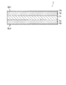
本実施形態では、熱膨張性シート7は、表と裏の両面に発泡樹脂層(膨張層)を備える構造になっている。具体的には、図2に示すように、熱膨張性シート7は、シート状の基材71と、吸収した熱量に応じて膨張する2つの発泡樹脂層(膨張層)72,74と、インク受容層73,75とを備えている。以下、発泡樹脂層(膨張層)72を「第1膨張層72」と称し、発泡樹脂層(膨張層)74を「第2膨張層74」と称する。また、熱膨張性シート7を「両面熱膨張性シート7」と称する場合がある。
In the present embodiment, the thermally
基材71は、熱膨張性シート7の中心層を構成している。基材71は、断熱材で構成されている。基材71は、紙、キャンバス地などの布、プラスチックなどのパネル材などからなり、材質は特に限定されるものではない。
The
基材71の断熱性能は、第1膨張層72を加熱して膨張させる際に、膨張層を膨張させることが可能な下限温度(例えば、80度程度)よりも低い温度に第2膨張層74の温度を維持することが可能になっている。
The heat insulation performance of the
第1及び第2膨張層72,74は、可塑性樹脂内に熱膨張性マイクロカプセル(熱発泡剤)が分散配置された構造になっている。第1膨張層72は、基材71の一方の面側に形成されている。第2膨張層74は、基材71の他方の面側に形成されている。以下、一方の面を「第1面」と称し、他方の面を「第2面」と称する。ここでは、第1面が上面であり、第2面が下面であるものとして説明する。
The first and second expansion layers 72 and 74 have a structure in which thermally expandable microcapsules (thermal foaming agents) are dispersedly arranged in a plastic resin. The
インク受容層73,75は、濃淡画像に使用されるインクを受容する層である。インク受容層73,75は、濃淡画像に使用されるインクを受容して、その表面に定着させるために好適な材料で構成されている。インク受容層73は、第1膨張層72の上面全体を覆うように配置されている。一方、インク受容層75は、第2膨張層74の下面全体を覆うように配置されている。インク受容層73,75の厚さは、例えば、10μm程度になっている。インク受容層73の上面とインク受容層75の下面は、平面状に形成されている。したがって、熱膨張性シート7の表面Su1と裏面Su2は、平面状に形成されている。
The ink receiving layers 73 and 75 are layers that receive ink used for a grayscale image. The ink receiving layers 73 and 75 are made of a material suitable for receiving ink used for a grayscale image and fixing it to the surface thereof. The
<立体画像の構造>
以下、図3〜図5を参照して、両面熱膨張性シート7に形成される立体画像の構造につき説明する。図3〜図5は、熱膨張性シート7の表面Su1に第1立体画像を形成し、裏面Su2に第2立体画像を形成した場合における熱膨張性シート7の断面形状の変化を示している。
<Structure of stereoscopic image>
Hereinafter, the structure of the stereoscopic image formed on the double-sided thermally
図3は、立体画像形成前の熱膨張性シート7Aの構造を示す断面図である。
図3に示すように、熱膨張性シート7Aは、表面Su1側のインク受容層73の上に電磁波熱変換層(濃淡画像)76が印刷されている。そして、一部の電磁波熱変換層76の上にカラーインク層77が印刷されている。また、熱膨張性シート7Aは、裏面Su2側のインク受容層75の上に電磁波熱変換層(濃淡画像)78が印刷されている。そして、一部の電磁波熱変換層78の上にカラーインク層79が印刷されている。電磁波熱変換層76,78は、例えばカーボンブラックを含むインクで印刷された層であり、可視光や近赤外光(電磁波)を熱に変換する。カラーインク層77,79は、シアン・マゼンタ・イエローなどのインクで構成されている。熱膨張性シート7Aの第1及び第2膨張層72,74は、加熱されていない。そのため、第1及び第2膨張層72,74の厚さは一様である。
FIG. 3 is a cross-sectional view showing the structure of the thermally
As shown in FIG. 3, the heat-
図1に示すように、熱膨張性シート7Aは、表面Su1を上に向けて、光照射ユニット4の給紙部50にセットされる。この場合に、光加熱手段(ランプヒータ44と反射板441)は、熱膨張性シート7Aの表面Su1を光の照射面とし、表面Su1に光を照射する。したがって、熱膨張性シート7Aは、光加熱手段(ランプヒータ44と反射板441)による可視光や近赤外光(電磁波)の照射を受ける。これにより、表面Su1側の第1膨張層72が膨張して、第1立体画像が表面Su1に形成される。その結果、図4に示す熱膨張性シート7Bが形成される。
As shown in FIG. 1, the thermally
なお、熱膨張性シート7の基材71は、断熱材で構成されている。また、光照射ユニット4は、冷却ファン91で熱膨張性シート7Aの照射面とは反対側の面(裏面Su2)を冷却する。そのため、このとき、光照射ユニット4は、意図せぬ裏面Su2側の第2膨張層74の膨張を抑制することができる。
In addition, the
図4は、第1立体画像形成後の熱膨張性シート7Bの構造を示す断面図である。
表面Su1側の電磁波熱変換層76は、表面Su1側から光の照射を受けて熱に変換する、この電磁波熱変換層76は、熱膨張性シート7に細かな立体パターンを形成するために設けられている。この電磁波熱変換層76の直下の第1膨張層72は、熱を受けて発泡膨張する。インク受容層73、電磁波熱変換層76、カラーインク層77は、それぞれ伸縮性を有し、第1膨張層72の発泡膨張に追従して変形する。このようにして熱膨張性シート7Bが形成される。
FIG. 4 is a cross-sectional view showing the structure of the thermally
The electromagnetic wave
次に、熱膨張性シート7Bは、裏面Su2を上に向けて、光照射ユニット4の給紙部50にセットされる。この場合に、光加熱手段(ランプヒータ44と反射板441)は、熱膨張性シート7Aの裏面Su2を光の照射面とし、裏面Su2に光を照射する。したがって、熱膨張性シート7Bは、光加熱手段(ランプヒータ44と反射板441)による可視光や近赤外光(電磁波)の照射を受ける。これにより、裏面Su2側の第2膨張層74が膨張して、第2立体画像が裏面Su2に形成される。その結果、図5に示す熱膨張性シート7Cが形成される。
Next, the thermally
なお、熱膨張性シート7の基材71は、断熱材で構成されている。また、光照射ユニット4は、冷却ファン91で熱膨張性シート7Aの照射面とは反対側の面(表面Su1)を冷却する。そのため、このとき、光照射ユニット4は、意図せぬ表面Su1側の第1膨張層72の膨張を抑制することができる。
In addition, the
図5は、第2立体画像形成後の熱膨張性シート7Cの構造を示す断面図である。
裏面Su2側の電磁波熱変換層78は、裏面Su2側から光の照射を受けて熱に変換する、この電磁波熱変換層78は、熱膨張性シート7に細かな立体パターンを形成するために設けられている。この電磁波熱変換層78の直下の第2膨張層74は、熱を受けて発泡膨張する。インク受容層75、電磁波熱変換層78、カラーインク層79は、それぞれ伸縮性を有し、第2膨張層74の発泡膨張に追従して変形する。このようにして熱膨張性シート7Cが形成される。
FIG. 5 is a cross-sectional view showing the structure of the thermally
The electromagnetic wave
<立体画像形成システムの立体画像形成時の動作>
以下、図6を参照して、立体画像形成システム1の立体画像形成時の動作につき説明する。図6は、立体画像形成システム1の立体画像形成時の動作を示すフローチャートである。ここでは、図3に示すように、電磁波熱変換層(濃淡画像)76,78が熱膨張性シート7の表面Su1と裏面Su2に既に形成されているものとして説明する。
<Operation of stereoscopic image forming system during stereoscopic image formation>
Hereinafter, with reference to FIG. 6, the operation of the stereoscopic
立体画像形成システム1のオペレータは、タッチパネルディスプレイ2を操作して立体画像の形成を立体画像形成システム1に指示する。そして、オペレータは、熱膨張性シート7の表面Su1を上に向けて、熱膨張性シート7を光照射ユニット4の給紙部50にセットする。これにより、光照射ユニット4は図6に示す処理を開始する。
An operator of the stereoscopic
図6に示すように、まず、ステップS110において、立体画像形成システム1の光照射ユニット4は、熱膨張性シート7の給紙部50へのセットを検知する。このとき、熱膨張性シート7の構造は、図3の熱膨張性シート7Aと同様の構造になっている。次に、ステップS120において、光照射ユニット4は、熱膨張性シート7の表面Su1に第1立体画像を形成する。
As shown in FIG. 6, first, in step S <b> 110, the
このとき、ステップS122において、光照射ユニット4は、光加熱手段(ランプヒータ44と反射板441)と熱膨張性シート7の照射面とは反対側の面を冷却するための冷却手段(冷却ファン91)とを作動させる。そして、ステップS124において、光照射ユニット4は、光加熱手段の周囲の温度(例えば反射板441の温度TH1)が膨張層を膨張させることが可能な下限温度以上の温度に到達したら、熱膨張性シート7の搬送を行う。
At this time, in step S122, the
これにより、光照射ユニット4は、光加熱手段で前記した下限温度以上の温度に熱膨張性シート7の照射面(表面Su1)を加熱しながら、冷却手段で前記した下限温度よりも低い温度に熱膨張性シート7の照射面とは反対側の面(裏面Su2)を冷却する。つまり、光照射ユニット4は、光加熱手段で熱膨張性シート7に光を照射して加熱する光照射工程と、冷却手段で熱膨張性シート7の光が照射されている照射面とは反対側の面を冷却する冷却工程と、を並行して行う。
As a result, the
光照射ユニット4は、上流側から下流側に向けて熱膨張性シート7を搬送して排出部(不図示)に排出する。このとき、熱膨張性シート7の構造は、図4の熱膨張性シート7Bと同様の構造になっている。すなわち、熱膨張性シート7は、図4の熱膨張性シート7Bと同様に、表面Su1側の第1膨張層72が膨張して、第1立体画像が表面Su1に形成された構造になっている。なお、このとき、裏面Su2側の第2膨張層74は膨張していない。したがって、第2立体画像は裏面Su2に形成されていない。
The
この後、ステップS130において、光照射ユニット4は、熱膨張性シート7が排出部(不図示)に排出されたことを出口センサ47で検知する。これに応答して、ステップS140において、光照射ユニット4は、光加熱手段(ランプヒータ44と反射板441)と冷却手段(冷却ファン91)を停止させる。
Thereafter, in step S <b> 130, the
この後、オペレータは、熱膨張性シート7の表面Su1と裏面Su2とを反転させ、熱膨張性シート7の裏面Su2を上に向けて、熱膨張性シート7を光照射ユニット4の給紙部50にセットする。これに応答して、ステップS160において、光照射ユニット4は、熱膨張性シート7の給紙部50へのセットを検知する。次に、ステップS170において、光照射ユニット4は、熱膨張性シート7の裏面Su2に第2立体画像を形成する。
Thereafter, the operator reverses the front surface Su1 and the rear surface Su2 of the thermally
このとき、ステップS172において、光照射ユニット4は、光加熱手段(ランプヒータ44と反射板441)と冷却手段(冷却ファン91)とを作動させる。そして、ステップS174において、光照射ユニット4は、光加熱手段の周囲の温度(例えば反射板441の温度TH1)が前記した下限温度以上の温度に到達したら、熱膨張性シート7の搬送を行う。
At this time, in step S172, the
これにより、光照射ユニット4は、光加熱手段で前記した下限温度以上の温度に熱膨張性シート7の照射面(裏面Su2)を加熱しながら、冷却手段で前記した下限温度よりも低い温度に熱膨張性シート7の照射面とは反対側の面(表面Su1)を冷却する。
Thereby, the
光照射ユニット4は、上流側から下流側に向けて熱膨張性シート7を搬送して排出部(不図示)に排出する。このとき、熱膨張性シート7の構造は、図5の熱膨張性シート7Cと同様の構造になっている。すなわち、熱膨張性シート7は、図5の熱膨張性シート7Cと同様に、表面Su1側の第1膨張層72及び裏面Su2側の第2膨張層74が膨張して、第1立体画像が表面Su1に形成されているとともに、第2立体画像が裏面Su2に形成された構造になっている。
The
この後、ステップS180において、光照射ユニット4は、熱膨張性シート7が排出部(不図示)に排出されたことを出口センサ47で検知する。これに応答して、ステップS190において、光照射ユニット4は、光加熱手段(ランプヒータ44と反射板441)と冷却手段(冷却ファン91)を停止させる。
これにより、一連のルーチンの処理(両面立体画像の形成処理)が終了する。
Thereafter, in step S <b> 180, the
Thus, a series of routine processing (double-sided stereoscopic image forming processing) is completed.
<立体画像形成システムの主な特徴>
係る構成において、本実施形態に係る立体画像形成システム1は、以下のような特徴を有している。
<Main features of stereoscopic image forming system>
In such a configuration, the stereoscopic
(1)立体画像形成システム1は、熱膨張性シート7を搬送しながら、熱膨張性シート7に光を照射して熱膨張性シート7を加熱する。それと並行して、立体画像形成システム1は、熱膨張性シート7の照射面とは反対側の面を冷却する。
(1) The three-dimensional
(2)立体画像形成システム1の光加熱手段は、前記した下限温度以上の温度に熱膨張性シート7の照射面を加熱する。その一方、立体画像形成システム1の冷却手段(冷却ファン91)は、前記した下限温度よりも低い温度に照射面とは反対側の面を冷却する。
(2) The light heating unit of the stereoscopic
このような立体画像形成システム1は、一方の面を加熱して膨張させる際に、一方の面に加えた熱の影響で他方の面の膨張させたくない部分までをも膨張させてしまうことを抑制することができる。そのため、立体画像形成システム1は、高品位な両面立体画像を形成することができる。
In such a stereoscopic
以上の通り、本実施形態に係る立体画像形成システム1によれば、高品位な両面立体画像を形成することができる。
As described above, according to the stereoscopic
なお、本発明は、前記した実施形態に限定されるものではなく、本発明の要旨を逸脱しない範囲で種々の変更や変形を行うことができる。
例えば、前記した実施形態は、本発明の要旨を分かり易く説明するために詳細に説明したものである。そのため、本発明は、必ずしも説明した全ての構成要素を備えるものに限定されるものではない。また、本発明は、ある構成要素に他の構成要素を追加したり、一部の構成要素を他の構成要素に変更したりすることができる。また、本発明は、一部の構成要素を削除することもできる。
例えば、光加熱手段は、レーザ光を照射する構成であってもよい。
In addition, this invention is not limited to above-described embodiment, A various change and deformation | transformation can be performed in the range which does not deviate from the summary of this invention.
For example, the above-described embodiment has been described in detail in order to easily understand the gist of the present invention. Therefore, the present invention is not necessarily limited to the one provided with all the constituent elements described. Further, according to the present invention, other components can be added to a certain component, or some components can be changed to other components. In the present invention, some components can be deleted.
For example, the light heating unit may be configured to irradiate laser light.
また、例えば、前記した実施形態では、入力手段は、表示手段である液晶表示パネルに張り合わされたタッチパネルとして構成されている。しかしながら、入力手段は、タッチパネルに限らず、様々な形態の入力装置で構成することができる。 Further, for example, in the above-described embodiment, the input unit is configured as a touch panel attached to a liquid crystal display panel which is a display unit. However, the input means is not limited to a touch panel, and can be configured by various forms of input devices.
また、例えば、立体画像形成システム1は、立体画像の基となる濃淡画像(電磁波熱変換層76,78)やカラーインク層77,79を熱膨張性シート7に印刷する印刷手段(不図示)を更に有する構成であってもよい。印刷手段は、例えば、インクジェットプリンタによって構成される。立体画像形成システム1のオペレータは、熱膨張性シート7をインクジェットプリンタにセットし、タッチパネルディスプレイ2を操作して濃淡画像の印刷を立体画像形成システム1に指示する。このとき、オペレータは、必要に応じてカラー画像の印刷を立体画像形成システム1に指示してもよい。オペレータがこのような処理を熱膨張性シート7の両面に対して行うことにより、濃淡画像やカラー画像が熱膨張性シート7の両面に印刷される。オペレータは、その熱膨張性シート7を光照射ユニット4にセットし、タッチパネルディスプレイ2を操作して立体画像の形成を立体画像形成システム1に指示する。オペレータがこのような処理を熱膨張性シート7の両面に対して行うことにより、立体画像が熱膨張性シート7の両面に形成される。
Further, for example, the stereoscopic
また、例えば、冷却手段は、図7〜図9に示す構成のように変形することができる。図7〜図9は、それぞれ、変形例に係る冷却手段の構成を示す図である。
図7は、入口センサ46(図1参照)側から挿入ローラ51,52(図1参照)側に向かって見たときの変形例に係る冷却手段の構成を示している。図7に示す例では、冷却手段が4つの冷却ファン91a〜91dによって構成されている。各冷却ファン91a〜91dは、搬送路6の近傍の位置に配置されている。各冷却ファン91a〜91dは、熱膨張性シート7の照射面とは反対側の面と対向するように、搬送路6の幅方向に並べて配置されている。このような冷却ファン91a〜91dは、冷却風を搬送路6に向けて送ることにより、搬送路6に沿って搬送される熱膨張性シート7の幅方向の全域を漏れなくかつ十分に冷却することができる。ただし、冷却ファン91の数は、4つに限らず、増減することができる。
Further, for example, the cooling means can be modified as shown in the configuration shown in FIGS. 7-9 is a figure which shows the structure of the cooling means which concerns on a modification, respectively.
FIG. 7 shows the configuration of the cooling means according to a modification when viewed from the inlet sensor 46 (see FIG. 1) side toward the
図8は、上側から見たときの別の変形例に係る冷却手段の構成を示している。図8に示す例では、冷却手段が冷却パイプ92によって構成されている。図8は、光加熱手段(ランプヒータ44と反射板441)を消去して、冷却パイプ92の構成を示している。冷却パイプ92は、内部を流体が流れるパイプである。冷却パイプ92は、搬送路6の近傍で、かつ、挿入ローラ51と排出ローラ53との間の位置に配置されている。冷却パイプ92は、熱膨張性シート7の照射面とは反対側の面と対向するように、また、搬送路6を幅方向に跨いで複数回往復するように配置されている。冷却パイプ92は、搬送路6の下方空間を冷却することにより、搬送路6に沿って搬送される熱膨張性シート7を冷却する。ただし、冷却パイプ92の構造は、これに限らず、変更することができる。
FIG. 8 shows the configuration of the cooling means according to another modification when viewed from above. In the example shown in FIG. 8, the cooling means is constituted by a cooling
図9は、左側から見たときの更に別の変形例に係る冷却手段の構成を示している。図9に示す例では、冷却手段が吸熱ローラ93によって構成されている。吸熱ローラ93は、熱膨張性シート7の照射面とは反対側の面と当接して、熱膨張性シート7から熱を吸収しながら熱膨張性シート7を搬送するローラである。吸熱ローラ93は、搬送路6の近傍で、かつ、挿入ローラ51,52と排出ローラ53,54との間の位置の位置に配置されている。なお、図9に示す例では、排出ローラ53,54は、挿入ローラ51,52よりも低い位置に配置されている。吸熱ローラ93は、円柱状のシャフト93aと、その外周に形成された円筒状の弾性部材93bとを備えている。シャフト93aは、金属材によって構成されており、図示せぬ冷却機構で冷却されている。弾性部材93bは、ゴム等で形成されている。弾性部材93bは、熱膨張性シート7の搬送時に、熱膨張性シート7に形成された立体画像が潰れないように、立体画像に対して柔軟に当接する。弾性部材93bは、熱膨張性シート7の照射面とは反対側の面からシャフト93aに熱を十分に伝達するための伝熱性能を有している。ここでは、吸熱ローラ93が駆動ローラであるものとして説明する。吸熱ローラ93の上方には、光加熱手段(ランプヒータ44と反射板441)が配置されている。また、吸熱ローラ93の周囲には、複数の従動ローラ94が配置されているとともに、挿入ローラ51,52を通過した熱膨張性シート7を従動ローラ94の方向に向けて誘導する図示せぬガイド部材が配置されている。また、従動ローラ94の下方には、熱膨張性シート7を排出ローラ53,54の方向に案内するガイド部材61が配置されている。吸熱ローラ93と従動ローラ94とは、互いの間で熱膨張性シート7を挟み込み、熱膨張性シート7をガイド部材61に向けて搬送する。その際に、光加熱手段(ランプヒータ44と反射板441)が熱膨張性シート7の一方の面を加熱する。また、図示せぬ冷却機構がシャフト93aを冷却する。これにより、吸熱ローラ93が熱膨張性シート7の他方の面から熱を吸収する。ただし、吸熱ローラ93の構造は、これに限らず、変更することができる。例えば、吸熱ローラ93は、内部を流体が流れる構造にしてもよい。この場合に、図示せぬ冷却機構は流体を冷却する。
FIG. 9 shows a configuration of a cooling means according to still another modified example when viewed from the left side. In the example shown in FIG. 9, the cooling means is constituted by a
以下に、この出願の願書に最初に添付した特許請求の範囲に記載した発明を付記する。付記に記載した請求項の項番は、この出願の願書に最初に添付した特許請求の範囲の通りである。
[付記]
《請求項1》
熱量に応じて膨張する熱膨張層を備えた熱膨張性シートに光を照射して加熱する光加熱手段と、
前記熱膨張性シートの光が照射されている照射面とは反対側の面を冷却する冷却手段と、を有することを特徴とする立体画像形成装置。
《請求項2》
前記光加熱手段により前記熱膨張性シートに光を照射すると共に、前記冷却手段により前記熱膨張性シートの照射面とは反対側の面を冷却することを特徴とする請求項1に記載の立体画像形成装置。
《請求項3》
前記光加熱手段は、前記熱膨張性シートに含まれている膨張層を膨張させることが可能な下限温度以上の温度に前記熱膨張性シートの照射面を加熱し、
前記冷却手段は、前記下限温度よりも低い温度に前記照射面とは反対側の面を冷却することを特徴とする請求項1又は請求項2に記載の立体画像形成装置。
《請求項4》
前記冷却手段は、前記照射面とは反対側の面に風を送る冷却ファンであることを特徴とする請求項1乃至請求項3のいずれか一項に記載の立体画像形成装置。
《請求項5》
前記冷却ファンは、複数設けられており、
それぞれの前記冷却ファンは、前記照射面とは反対側の面と対向するように、搬送路の幅方向に並べて配置されていることを特徴とする請求項4に記載の立体画像形成装置。
《請求項6》
前記冷却手段は、内部を流体が流れる冷却パイプであり、
前記冷却パイプは、前記照射面とは反対側の面と対向するように配置されていることを特徴とする請求項1乃至請求項3のいずれか一項に記載の立体画像形成装置。
《請求項7》
前記冷却手段は、熱を吸収しながら前記熱膨張性シートを搬送する吸熱ローラであり、
前記吸熱ローラは、前記照射面とは反対側の面と当接するように配置されていることを特徴とする請求項1乃至請求項3のいずれか一項に記載の立体画像形成装置。
《請求項8》
請求項1乃至請求項7のいずれか一項に記載の立体画像形成装置と、
前記立体画像形成装置に光照射を指示する入力手段と、を有することを特徴とする立体画像形成システム。
《請求項9》
立体画像の基となる濃淡画像を熱膨張性シートに印刷する印刷手段を更に有することを特徴とする請求項8に記載の立体画像形成システム。
《請求項10》
搬送手段で熱膨張性シートを搬送しながら、光加熱手段で前記熱膨張性シートに光を照射して加熱する光照射工程と、
冷却手段で前記熱膨張性シートの光が照射されている照射面とは反対側の面を冷却する冷却工程と、を含み、
前記光照射工程と前記冷却工程とが並行して行われることを特徴とする立体画像形成方法。
《請求項11》
前記熱膨張性シートの一方の面である第1面に立体画像を形成する第1立体画像形成工程と、
前記熱膨張性シートの他方の面である第2面に立体画像を形成する第2立体画像形成工程と、を含み、
前記第1立体画像形成工程では、前記第1面が前記光加熱手段に対向するように、前記熱膨張性シートを搬送しながら、前記光照射工程と前記冷却工程とを行い、
前記第2立体画像形成工程では、前記第2面が前記光加熱手段に対向するように、前記熱膨張性シートを搬送しながら、前記光照射工程と前記冷却工程とを行うことを特徴とする請求項10に記載の立体画像形成方法。
《請求項12》
シート状の基材と、
前記基材の一方の面側に形成され、かつ、吸収した熱量に応じて膨張する第1膨張層と、
前記基材の他方の面側に形成され、かつ、吸収した熱量に応じて膨張する第2膨張層と、を備え、
前記基材は、断熱材で構成されており、
前記基材の断熱性能は、前記第1膨張層を加熱して膨張させる際に、膨張層を膨張させることが可能な下限温度よりも低い温度に前記第2膨張層の温度を維持することが可能になっていることを特徴とする熱膨張性シート。
The invention described in the scope of claims attached to the application of this application will be added below. The item numbers of the claims described in the appendix are as set forth in the claims attached to the application of this application.
[Appendix]
<Claim 1>
A light heating means for irradiating and heating a heat-expandable sheet provided with a thermal expansion layer that expands according to the amount of heat;
A three-dimensional image forming apparatus comprising: a cooling unit that cools a surface opposite to an irradiation surface on which light of the thermally expandable sheet is irradiated.
<Claim 2>
2. The three-dimensional object according to
<Claim 3>
The light heating means heats the irradiated surface of the thermally expandable sheet to a temperature equal to or higher than a lower limit temperature capable of expanding the expanded layer contained in the thermally expandable sheet,
The three-dimensional image forming apparatus according to
<Claim 4>
The stereoscopic image forming apparatus according to
<Claim 5>
A plurality of the cooling fans are provided,
5. The three-dimensional image forming apparatus according to
<Claim 6>
The cooling means is a cooling pipe through which a fluid flows,
The stereoscopic image forming apparatus according to
<Claim 7>
The cooling means is a heat absorbing roller that conveys the thermally expandable sheet while absorbing heat,
The three-dimensional image forming apparatus according to any one of
<Claim 8>
A stereoscopic image forming apparatus according to any one of
A stereoscopic image forming system comprising: input means for instructing the stereoscopic image forming apparatus to irradiate light.
<< Claim 9 >>
9. The three-dimensional image forming system according to
<Claim 10>
A light irradiating step of irradiating and heating the thermally expandable sheet with a light heating means while conveying the thermally expandable sheet with a conveying means;
A cooling step of cooling a surface opposite to the irradiation surface irradiated with light of the thermally expandable sheet by a cooling means,
The three-dimensional image forming method, wherein the light irradiation step and the cooling step are performed in parallel.
<Claim 11>
A first stereoscopic image forming step of forming a stereoscopic image on a first surface which is one surface of the thermally expandable sheet;
A second stereoscopic image forming step of forming a stereoscopic image on the second surface which is the other surface of the thermally expandable sheet,
In the first stereoscopic image forming step, the light irradiating step and the cooling step are performed while conveying the thermally expandable sheet so that the first surface faces the light heating unit,
In the second stereoscopic image forming step, the light irradiation step and the cooling step are performed while the thermally expandable sheet is conveyed so that the second surface faces the light heating unit. The three-dimensional image forming method according to claim 10.
<Claim 12>
A sheet-like substrate;
A first expansion layer formed on one side of the substrate and expanding in accordance with the amount of heat absorbed;
A second expansion layer that is formed on the other surface side of the base material and expands according to the amount of heat absorbed, and
The base material is composed of a heat insulating material,
The heat insulating performance of the base material is that when the first expansion layer is heated and expanded, the temperature of the second expansion layer is maintained at a temperature lower than a lower limit temperature at which the expansion layer can be expanded. A heat-expandable sheet characterized by being made possible.
1 立体画像形成システム
2 タッチパネルディスプレイ(入力手段、表示手段)
4 光照射ユニット(立体画像形成装置)
44 ランプヒータ(光加熱手段の一部)
441 反射板(光加熱手段の一部)
51,52 挿入ローラ(搬送手段)
53,54 排出ローラ(搬送手段)
6 搬送路
7,7A,7B,7C 熱膨張性シート(両面熱膨張性シート)
71 基材
72 発泡樹脂層(第1膨張層)
73,75 インク受容層
74 発泡樹脂層(第2膨張層)
76,78 電磁波熱変換層(濃淡画像)
77,79 カラーインク層
91 冷却ファン(冷却手段)
Su1 第1面
Su2 第2面
1 stereoscopic
4 Light irradiation unit (stereoscopic image forming device)
44 Lamp heater (part of light heating means)
441 Reflector (part of light heating means)
51, 52 Insertion roller (conveying means)
53, 54 Discharge roller (conveyance means)
6
71
73,75
76, 78 Electromagnetic heat conversion layer (grayscale image)
77, 79
Su1 first surface Su2 second surface
Claims (12)
前記熱膨張性シートの光が照射されている照射面とは反対側の面を冷却する冷却手段と、を有することを特徴とする立体画像形成装置。 A light heating means for irradiating and heating a heat-expandable sheet provided with a thermal expansion layer that expands according to the amount of heat;
A three-dimensional image forming apparatus comprising: a cooling unit that cools a surface opposite to an irradiation surface on which light of the thermally expandable sheet is irradiated.
前記冷却手段は、前記下限温度よりも低い温度に前記照射面とは反対側の面を冷却することを特徴とする請求項1又は請求項2に記載の立体画像形成装置。 The light heating means heats the irradiated surface of the thermally expandable sheet to a temperature equal to or higher than a lower limit temperature capable of expanding the expanded layer contained in the thermally expandable sheet,
The three-dimensional image forming apparatus according to claim 1, wherein the cooling unit cools a surface opposite to the irradiation surface to a temperature lower than the lower limit temperature.
それぞれの前記冷却ファンは、前記照射面とは反対側の面と対向するように、搬送路の幅方向に並べて配置されていることを特徴とする請求項4に記載の立体画像形成装置。 A plurality of the cooling fans are provided,
5. The three-dimensional image forming apparatus according to claim 4, wherein the cooling fans are arranged side by side in the width direction of the transport path so as to face a surface opposite to the irradiation surface.
前記冷却パイプは、前記照射面とは反対側の面と対向するように配置されていることを特徴とする請求項1乃至請求項3のいずれか一項に記載の立体画像形成装置。 The cooling means is a cooling pipe through which a fluid flows,
The stereoscopic image forming apparatus according to claim 1, wherein the cooling pipe is disposed so as to face a surface opposite to the irradiation surface.
前記吸熱ローラは、前記照射面とは反対側の面と当接するように配置されていることを特徴とする請求項1乃至請求項3のいずれか一項に記載の立体画像形成装置。 The cooling means is a heat absorbing roller that conveys the thermally expandable sheet while absorbing heat,
The three-dimensional image forming apparatus according to any one of claims 1 to 3, wherein the heat absorption roller is disposed so as to contact a surface opposite to the irradiation surface.
前記立体画像形成装置に光照射を指示する入力手段と、を有することを特徴とする立体画像形成システム。 A stereoscopic image forming apparatus according to any one of claims 1 to 7,
A stereoscopic image forming system comprising: input means for instructing the stereoscopic image forming apparatus to irradiate light.
冷却手段で前記熱膨張性シートの光が照射されている照射面とは反対側の面を冷却する冷却工程と、を含み、
前記光照射工程と前記冷却工程とが並行して行われることを特徴とする立体画像形成方法。 A light irradiating step of irradiating and heating the thermally expandable sheet with a light heating means while conveying the thermally expandable sheet with a conveying means;
A cooling step of cooling a surface opposite to the irradiation surface irradiated with light of the thermally expandable sheet by a cooling means,
The three-dimensional image forming method, wherein the light irradiation step and the cooling step are performed in parallel.
前記熱膨張性シートの他方の面である第2面に立体画像を形成する第2立体画像形成工程と、を含み、
前記第1立体画像形成工程では、前記第1面が前記光加熱手段に対向するように、前記熱膨張性シートを搬送しながら、前記光照射工程と前記冷却工程とを行い、
前記第2立体画像形成工程では、前記第2面が前記光加熱手段に対向するように、前記熱膨張性シートを搬送しながら、前記光照射工程と前記冷却工程とを行うことを特徴とする請求項10に記載の立体画像形成方法。 A first stereoscopic image forming step of forming a stereoscopic image on a first surface which is one surface of the thermally expandable sheet;
A second stereoscopic image forming step of forming a stereoscopic image on the second surface which is the other surface of the thermally expandable sheet,
In the first stereoscopic image forming step, the light irradiating step and the cooling step are performed while conveying the thermally expandable sheet so that the first surface faces the light heating unit,
In the second stereoscopic image forming step, the light irradiation step and the cooling step are performed while the thermally expandable sheet is conveyed so that the second surface faces the light heating unit. The three-dimensional image forming method according to claim 10.
前記基材の一方の面側に形成され、かつ、吸収した熱量に応じて膨張する第1膨張層と、
前記基材の他方の面側に形成され、かつ、吸収した熱量に応じて膨張する第2膨張層と、を備え、
前記基材は、断熱材で構成されており、
前記基材の断熱性能は、前記第1膨張層を加熱して膨張させる際に、膨張層を膨張させることが可能な下限温度よりも低い温度に前記第2膨張層の温度を維持することが可能になっていることを特徴とする熱膨張性シート。 A sheet-like substrate;
A first expansion layer formed on one side of the substrate and expanding in accordance with the amount of heat absorbed;
A second expansion layer that is formed on the other surface side of the base material and expands according to the amount of heat absorbed, and
The base material is composed of a heat insulating material,
The heat insulating performance of the base material is that when the first expansion layer is heated and expanded, the temperature of the second expansion layer is maintained at a temperature lower than a lower limit temperature at which the expansion layer can be expanded. A heat-expandable sheet characterized by being made possible.
Priority Applications (1)
| Application Number | Priority Date | Filing Date | Title |
|---|---|---|---|
| JP2016155179A JP6862713B2 (en) | 2016-08-08 | 2016-08-08 | Stereoscopic image forming apparatus, stereoscopic image forming system, stereoscopic image forming method, and thermally expandable sheet |
Applications Claiming Priority (1)
| Application Number | Priority Date | Filing Date | Title |
|---|---|---|---|
| JP2016155179A JP6862713B2 (en) | 2016-08-08 | 2016-08-08 | Stereoscopic image forming apparatus, stereoscopic image forming system, stereoscopic image forming method, and thermally expandable sheet |
Publications (2)
| Publication Number | Publication Date |
|---|---|
| JP2018024103A true JP2018024103A (en) | 2018-02-15 |
| JP6862713B2 JP6862713B2 (en) | 2021-04-21 |
Family
ID=61194417
Family Applications (1)
| Application Number | Title | Priority Date | Filing Date |
|---|---|---|---|
| JP2016155179A Active JP6862713B2 (en) | 2016-08-08 | 2016-08-08 | Stereoscopic image forming apparatus, stereoscopic image forming system, stereoscopic image forming method, and thermally expandable sheet |
Country Status (1)
| Country | Link |
|---|---|
| JP (1) | JP6862713B2 (en) |
Cited By (9)
| Publication number | Priority date | Publication date | Assignee | Title |
|---|---|---|---|---|
| JP2019142198A (en) * | 2018-02-23 | 2019-08-29 | カシオ計算機株式会社 | Lighting device and molding system |
| JP2020004875A (en) * | 2018-06-28 | 2020-01-09 | カシオ計算機株式会社 | Heat-expandable sheet coated with conductive film, wiring board, and manufacturing method thereof |
| JP2020032671A (en) * | 2018-08-31 | 2020-03-05 | カシオ計算機株式会社 | Heat-expansive sheet and method for producing the same, and shaped article and method for producing the same |
| JP2020163863A (en) * | 2020-06-19 | 2020-10-08 | カシオ計算機株式会社 | Electromagnetic wave irradiation mechanism |
| JP2021035750A (en) * | 2019-08-30 | 2021-03-04 | 株式会社リコー | Method for manufacturing printed matter, and apparatus for manufacturing printed matter |
| JP2021044597A (en) * | 2020-12-23 | 2021-03-18 | カシオ計算機株式会社 | Circuit board, program, and button structure |
| JP2021061421A (en) * | 2020-12-23 | 2021-04-15 | カシオ計算機株式会社 | program |
| JP2021151769A (en) * | 2020-03-24 | 2021-09-30 | カシオ計算機株式会社 | Modeling device and manufacturing method of modeled article |
| US11420380B2 (en) * | 2020-03-24 | 2022-08-23 | Casio Computer Co., Ltd. | Shaping device and production method for shaped object |
Citations (7)
| Publication number | Priority date | Publication date | Assignee | Title |
|---|---|---|---|---|
| US4268615A (en) * | 1979-05-23 | 1981-05-19 | Matsumoto Yushi-Seiyaku Co., Ltd. | Method for producing relief |
| JPH07246767A (en) * | 1994-03-09 | 1995-09-26 | Brother Ind Ltd | Stereoscopic image label and method for forming stereoscopic image label |
| JPH08118780A (en) * | 1994-10-19 | 1996-05-14 | Brother Ind Ltd | Method for producing sheet with stereoscopic image, image forming apparatus, and sheet for stereoscopic image formation |
| JP2001287435A (en) * | 2000-02-02 | 2001-10-16 | Dainippon Printing Co Ltd | Braille and raised pattern recording media |
| JP2003072217A (en) * | 2001-09-04 | 2003-03-12 | Dainippon Printing Co Ltd | Three-dimensional figure recording medium, three-dimensional figure recording method, and method of using the same |
| EP1683826A2 (en) * | 2005-01-25 | 2006-07-26 | Hansgeorg Neubig | Process for manufacturing a defined three-dimensional relief-like structure on the surface of a support, layered composite for preparation of such process and use of a structure prepared by such process |
| JP2013129144A (en) * | 2011-12-22 | 2013-07-04 | Casio Computer Co Ltd | Apparatus and method for forming three-dimensional image |
-
2016
- 2016-08-08 JP JP2016155179A patent/JP6862713B2/en active Active
Patent Citations (7)
| Publication number | Priority date | Publication date | Assignee | Title |
|---|---|---|---|---|
| US4268615A (en) * | 1979-05-23 | 1981-05-19 | Matsumoto Yushi-Seiyaku Co., Ltd. | Method for producing relief |
| JPH07246767A (en) * | 1994-03-09 | 1995-09-26 | Brother Ind Ltd | Stereoscopic image label and method for forming stereoscopic image label |
| JPH08118780A (en) * | 1994-10-19 | 1996-05-14 | Brother Ind Ltd | Method for producing sheet with stereoscopic image, image forming apparatus, and sheet for stereoscopic image formation |
| JP2001287435A (en) * | 2000-02-02 | 2001-10-16 | Dainippon Printing Co Ltd | Braille and raised pattern recording media |
| JP2003072217A (en) * | 2001-09-04 | 2003-03-12 | Dainippon Printing Co Ltd | Three-dimensional figure recording medium, three-dimensional figure recording method, and method of using the same |
| EP1683826A2 (en) * | 2005-01-25 | 2006-07-26 | Hansgeorg Neubig | Process for manufacturing a defined three-dimensional relief-like structure on the surface of a support, layered composite for preparation of such process and use of a structure prepared by such process |
| JP2013129144A (en) * | 2011-12-22 | 2013-07-04 | Casio Computer Co Ltd | Apparatus and method for forming three-dimensional image |
Cited By (12)
| Publication number | Priority date | Publication date | Assignee | Title |
|---|---|---|---|---|
| JP2019142198A (en) * | 2018-02-23 | 2019-08-29 | カシオ計算機株式会社 | Lighting device and molding system |
| JP7013930B2 (en) | 2018-02-23 | 2022-02-01 | カシオ計算機株式会社 | Irradiation device and modeling system |
| JP2020004875A (en) * | 2018-06-28 | 2020-01-09 | カシオ計算機株式会社 | Heat-expandable sheet coated with conductive film, wiring board, and manufacturing method thereof |
| JP2020032671A (en) * | 2018-08-31 | 2020-03-05 | カシオ計算機株式会社 | Heat-expansive sheet and method for producing the same, and shaped article and method for producing the same |
| JP2021035750A (en) * | 2019-08-30 | 2021-03-04 | 株式会社リコー | Method for manufacturing printed matter, and apparatus for manufacturing printed matter |
| JP2021151769A (en) * | 2020-03-24 | 2021-09-30 | カシオ計算機株式会社 | Modeling device and manufacturing method of modeled article |
| US11420380B2 (en) * | 2020-03-24 | 2022-08-23 | Casio Computer Co., Ltd. | Shaping device and production method for shaped object |
| JP7143877B2 (en) | 2020-03-24 | 2022-09-29 | カシオ計算機株式会社 | Modeling apparatus and modeled product manufacturing method |
| JP2020163863A (en) * | 2020-06-19 | 2020-10-08 | カシオ計算機株式会社 | Electromagnetic wave irradiation mechanism |
| JP7070608B2 (en) | 2020-06-19 | 2022-05-18 | カシオ計算機株式会社 | Electromagnetic wave irradiation mechanism, model manufacturing system, and model manufacturing method |
| JP2021044597A (en) * | 2020-12-23 | 2021-03-18 | カシオ計算機株式会社 | Circuit board, program, and button structure |
| JP2021061421A (en) * | 2020-12-23 | 2021-04-15 | カシオ計算機株式会社 | program |
Also Published As
| Publication number | Publication date |
|---|---|
| JP6862713B2 (en) | 2021-04-21 |
Similar Documents
| Publication | Publication Date | Title |
|---|---|---|
| JP6862713B2 (en) | Stereoscopic image forming apparatus, stereoscopic image forming system, stereoscopic image forming method, and thermally expandable sheet | |
| JP5672289B2 (en) | Stereoscopic image forming apparatus and stereoscopic image forming method | |
| JP5212504B2 (en) | 3D printing apparatus, 3D printing system, and 3D printing method | |
| JP5915673B2 (en) | 3D printing apparatus and 3D image forming method | |
| JP6531350B2 (en) | Three-dimensional image forming apparatus, three-dimensional image forming method, and three-dimensional image forming program | |
| JP5862276B2 (en) | Stereoscopic image forming apparatus and stereoscopic image forming method | |
| JP6414148B2 (en) | Stereoscopic image forming system | |
| CN108621523B (en) | Expansion device, stereoscopic image forming system, expansion method of thermal expansion sheet, and computer-readable storage medium | |
| JP6372601B2 (en) | Manufacturing method of modeling object and modeling apparatus | |
| CN107776227B (en) | Three-dimensional shaped object production method, printing data production device and recording medium | |
| CN113442619A (en) | Molding device and method for manufacturing molded article | |
| JP6903909B2 (en) | Method of manufacturing light irradiation device and modeled object | |
| JP6432241B2 (en) | Stereoscopic image forming apparatus, stereoscopic image forming method, pattern data generating method, and program | |
| JP2017226114A (en) | Stereoscopic image forming system and thermally expandable sheet conveying method | |
| JP6540140B2 (en) | Stereoscopic image forming method and stereographic image forming system | |
| JP6852305B2 (en) | Light irradiation device | |
| CN108569044B (en) | Stereoscopic image forming system and method, and computer-readable storage medium | |
| JP6923042B2 (en) | Irradiation unit, expansion method of heat-expandable sheet, and stereoscopic image formation method | |
| JP6844598B2 (en) | 3D image formation system, program and manufacturing method of modeled object | |
| JP7283158B2 (en) | Modeled product manufacturing method, transfer device, and modeling system | |
| JP7143877B2 (en) | Modeling apparatus and modeled product manufacturing method | |
| JP6787446B2 (en) | Manufacturing method of the modeled object | |
| JP2021091226A (en) | Production method of stereoscopic image | |
| JP2019133405A (en) | Identifier reading mechanism | |
| JP2021181231A (en) | Irradiation unit and manufacturing method of stereoscopic image |
Legal Events
| Date | Code | Title | Description |
|---|---|---|---|
| A621 | Written request for application examination |
Free format text: JAPANESE INTERMEDIATE CODE: A621 Effective date: 20190722 |
|
| A977 | Report on retrieval |
Free format text: JAPANESE INTERMEDIATE CODE: A971007 Effective date: 20200601 |
|
| A131 | Notification of reasons for refusal |
Free format text: JAPANESE INTERMEDIATE CODE: A131 Effective date: 20200714 |
|
| A521 | Request for written amendment filed |
Free format text: JAPANESE INTERMEDIATE CODE: A523 Effective date: 20200824 |
|
| TRDD | Decision of grant or rejection written | ||
| A01 | Written decision to grant a patent or to grant a registration (utility model) |
Free format text: JAPANESE INTERMEDIATE CODE: A01 Effective date: 20210302 |
|
| A61 | First payment of annual fees (during grant procedure) |
Free format text: JAPANESE INTERMEDIATE CODE: A61 Effective date: 20210315 |
|
| R150 | Certificate of patent or registration of utility model |
Ref document number: 6862713 Country of ref document: JP Free format text: JAPANESE INTERMEDIATE CODE: R150 |