JP2018024104A - Latent image printed matter - Google Patents
Latent image printed matter Download PDFInfo
- Publication number
- JP2018024104A JP2018024104A JP2016155243A JP2016155243A JP2018024104A JP 2018024104 A JP2018024104 A JP 2018024104A JP 2016155243 A JP2016155243 A JP 2016155243A JP 2016155243 A JP2016155243 A JP 2016155243A JP 2018024104 A JP2018024104 A JP 2018024104A
- Authority
- JP
- Japan
- Prior art keywords
- element group
- latent image
- light
- image
- light reflecting
- Prior art date
- Legal status (The legal status is an assumption and is not a legal conclusion. Google has not performed a legal analysis and makes no representation as to the accuracy of the status listed.)
- Pending
Links
Images


Landscapes
- Credit Cards Or The Like (AREA)
- Printing Methods (AREA)
Abstract
【課題】 印刷画像に対する反射光量を高めるとともに色彩表現を豊かにし、出現する潜像の視認性が高くかつ同じ領域内に動的効果を奏する潜像画像とモアレ模様を配しても、それぞれの視認性が低下しない潜像印刷物を提供する。【解決手段】 樹脂を含む材料により形成された蒲鉾状要素群と、正反射光下において蒲鉾状要素と異なる色彩の明暗フリップフロップ性又はカラーフリップフロップ性の少なくとも一方の光学特性を備えた光反射要素群と、基画像を分割及び/又は圧縮した透明又は半透明の潜像要素群から成る印刷画像が形成され、蒲鉾状要素群の上に、光反射要素群、潜像要素群の順に積層又は潜像要素群、光反射要素群の順に積層され、蒲鉾状要素群及び光反射要素群は、要素のピッチ、配置角度、形状のいずれか一つが異なることで要素群同士の干渉によりモアレ模様が形成される。【選択図】 図5PROBLEM TO BE SOLVED: To increase the amount of reflected light with respect to a printed image and enrich the color expression, and to arrange a latent image and a moiré pattern which have a high visibility of an appearing latent image and exhibit a dynamic effect in the same area. Provided is a latent image print that does not reduce visibility. SOLUTION: A semi-cylindrical element group formed of a resin-containing material and a light reflection having at least one of a light-dark flip-flop property and a color flip-flop property of a color different from that of the semi-cylindrical element under regular reflection light A print image composed of a group of elements and a transparent or translucent latent image element group obtained by dividing and / or compressing the base image is formed, and a light reflection element group and a latent image element group are laminated on the Kamaboko element group in this order. Alternatively, the latent image element group and the light reflection element group are laminated in this order, and the kabama-shaped element group and the light reflection element group are different in any one of the element pitch, the arrangement angle, and the shape, so that the moire pattern is caused by interference between the element groups. Is formed. [Selection diagram] FIG.
Description
本発明は、偽造防止効果を必要とする銀行券、パスポート、有価証券、身分証明書、カード、通行券等のセキュリティ印刷物の分野において、光が入射することで、画像のチェンジ効果、あるいは動画的な視覚効果が生じる、高い真偽判別性と偽造抵抗力を備えた潜像印刷物に関する。 In the field of security printed matter such as banknotes, passports, securities, identification cards, cards, and passports that require anti-counterfeiting effects, the present invention allows image change effects or video effects. The present invention relates to a latent image printed matter having high authenticity discrimination and counterfeit resistance that produces a good visual effect.
複数の画像が切り替わる画像のチェンジ効果や、画像が動いて見える動画効果は、人目を惹きやすく、偽造することが困難であることから、近年、セキュリティ印刷物の真偽判別要素として用いられる傾向にある。これらの効果を備えた代表的な技術は、ホログラムであり、チェンジ効果や動画効果を有する様々な形態で、銀行券やパスポート等の高度なセキュリティが要求されるセキュリティ印刷物にも貼付されて広く用いられている。 The image change effect of switching between multiple images and the moving image effect of moving images tend to be eye-catching and difficult to counterfeit. . A typical technology with these effects is holograms, which are widely used in various forms with change effects and video effects, and are also affixed to security prints that require high security such as banknotes and passports. It has been.
一方、ホログラム以外にも、パララックスバリアやレンチキュラー等の公知技術を用い、僅かな角度変化で複数の画像が切り替わる画像のチェンジ効果や、画像が動いて見える動画効果を備えた真偽判別要素も、既に存在している。 On the other hand, in addition to holograms, there are also true / false discriminating elements that use known techniques such as parallax barriers and lenticulars, and that have image change effects in which multiple images are switched by slight angle changes, and video effects that make the images appear to move. Already exists.
しかし、ホログラムは、銀行券を代表とする各種セキュリティ印刷物に用いられているものの、一般的な印刷物と比較すると、製造工程の複雑さと高い製造コストに大きな問題がある。パララックスバリアやレンチキュラー、マイクロレンズアレイ等を用いた真偽判別要素は、クリア層かレンズが必要となることから、基材がほぼプラスティックに限定される上、印刷物には一定の厚み(少なくとも150μm程度)が必要となり、厚さに制限のある印刷物には用いることができず、一定の厚みが許されるプラスティック製カード以外には採用されない傾向にある。 However, although holograms are used for various security printed materials such as banknotes, there are significant problems in the complexity of the manufacturing process and high manufacturing costs compared to general printed materials. Truth discrimination elements using a parallax barrier, lenticular, microlens array, etc. require a clear layer or lens, so the base material is almost limited to plastic, and the printed material has a certain thickness (at least 150 μm) However, it cannot be used for printed matter with a limited thickness, and tends to be used only for plastic cards that allow a certain thickness.
以上の問題を解決するため、本出願人は、高光沢で盛り上がりを有した蒲鉾状画線群の上に潜像画線群を重ね合わせて形成する技術であって、潜像画線群の中の複数の潜像が観察角度に応じてチェンジする効果を実現した偽造防止技術を既に出願している(例えば、特許文献1及び特許文献2参照)。この技術は、蒲鉾状画線に特定の角度で光が入射した場合に、蒲鉾状画線群の画線表面のうち、入射光と直交する角度を成す画線表面のみが強く光を反射する現象を利用することで、光を反射した画線表面に重ねられた潜像画線群の一部の潜像のみが反射光量や色彩の違いによって可視化される。また、パララックスバリアやレンチキュラーの10分の1程度の厚さで形成することが可能であって、製造技術も従来からある製版技術と印刷技術を活用することで容易に実施可能であり、かつ、一般的な印刷物と同じコストでホログラムと同様なチェンジ効果を備えた印刷画像を形成することができるという優れた特徴を有する。
In order to solve the above problems, the present applicant is a technique for forming a latent image line group by superimposing a latent image line group on a high-gloss and ridge-like line group. An application has been filed for a forgery prevention technique that realizes an effect of changing a plurality of latent images in accordance with an observation angle (see, for example,
また、これらの特許文献1や特許文献2の技術を応用した技術として、微細な模様同士が干渉し、模様の一部がサンプリングされることで拡大されたモアレ模様として視認される現象(モアレ拡大現象)やインテグラルフォトグラフィ方式の画線構成を用いて、特殊な立体的な視覚効果と動画的な視覚効果を実現した形態の技術が存在する(例えば、特許文献3、特許文献4及び特許文献5参照)。この技術は、正反射光下で出現した潜像が入射光の角度や観察者の観察位置に応じて立体感を伴いながら左右に動いて見えるという効果を有する。
In addition, as a technique applying these techniques of
加えて、特許文献1から特許文献5までの技術の効果をエンボス加工と光反射要素群の組合せによって実現した技術が存在する(例えば、特許文献6参照)。そして、特許文献1から特許文献5までの技術の原理を用いて、色彩変化の効果をより高めた技術も存在する(例えば、特許文献7及び特許文献8参照)。
In addition, there is a technique that realizes the effects of the techniques of
特許文献1から特許文献6までに記載の全ての従来技術に共通した問題として、正反射光下において、印刷画像中に表現することができる色彩が制限されるという問題があった。特許文献1から特許文献6までに記載のいずれの技術においても、その効果発現の原理に基づく制約から、正反射光下で出現する画像が表現できる色彩は、蒲鉾状要素群が拡散反射光下から正反射光下にかけて発することができる色彩に限定される。
As a problem common to all the conventional techniques described in
仮に、蒲鉾状要素群がカラーフリップフロップ性を備えていたとして、拡散反射光下では黒色で、正反射光下では金色に変化する特性を有していた場合、正反射光下で表現できる色彩は、暗い黒から明るい金色までの合成色のグラデーションのみであり、加えて潜像要素群によって形成される基画像には、正反射光下での蒲鉾状要素群の色彩の明るさを最大として、それより暗い色彩しか表現できない。 Assuming that the saddle-shaped element group has color flip-flop properties, the color that can be expressed under specular reflection light if it has a characteristic of changing to black under diffuse reflection light and gold under specular reflection light. Is only the gradation of the composite color from dark black to light gold, and the base image formed by the latent image element group has the maximum brightness of the color of the saddle-shaped element group under specular reflection light. Only darker colors can be expressed.
以上のように、それぞれの技術において印刷画像中に表現できる色彩は蒲鉾状要素群の光学特性に支配されており、この蒲鉾状要素群に、いかに優れた機能性顔料を用いたとしても一つの要素単体で表現できる色彩表現域には限界があり、結果として印刷画像中に適用できる色彩表現域が狭いという問題があった。 As described above, the colors that can be expressed in the printed image in each technology are governed by the optical characteristics of the saddle-like element group, and no matter how excellent functional pigment is used for this saddle-like element group, There is a limit to the color expression range that can be expressed by a single element, and as a result, there is a problem that the color expression range that can be applied to a printed image is narrow.
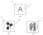
また、上記の印刷画像中に適用できる色彩表現域が狭いという問題に端を発し、図20(a)に示すように、正反射光下で出現する基画像(f)の周囲の背景には、一定のブランク(g)があった方が好ましいというデザイン上の制約が同時に生じていた。具体的に説明すると、仮に図20(b)や図20(c)に示すように、正反射光下で出現する基画像(f)と、基画像(f)と隣接した背景に基画像(f)とは別の模様(h又はi)を配置した場合、前述のとおり印刷画像中で表現可能な色彩は限定されているため、基画像(f)と模様(h又はi)は同じ色相に属する、完全に同じ色彩か、あるいは明暗のみが異なる色彩でしか表現不可能であって、結果的に互いの階調を相殺し、基画像(f)と模様(h又はi)の視認性が相互に損なわれるという問題があった。 Also, the background of the base image (f) appearing under specular reflection light, as shown in FIG. 20 (a), originates from the problem that the color expression range applicable to the printed image is narrow. At the same time, there was a design restriction that it would be preferable to have a certain blank (g). Specifically, as shown in FIGS. 20B and 20C, a base image (f) that appears under specular reflection light and a base image ( When a pattern (h or i) different from f) is arranged, the colors that can be expressed in the printed image are limited as described above, and therefore the base image (f) and the pattern (h or i) have the same hue. Can be expressed only in completely the same color or in different colors only in light and dark, and as a result, the gradation of each other is canceled, and the visibility of the base image (f) and the pattern (h or i) There was a problem that they were damaged.
この問題は、特に、背景にモアレ模様(i)のような動きを生じる模様を配置した場合により顕著であった。これは、モアレ模様(i)が、単純な模様(h)のように、単に基画像(f)と同じインキによって同じ版面上に構成されるというだけではなく、基画像(f)と同じく蒲鉾状画線と同じ規則に従って部分的に干渉することによって、模様の一部の情報のみがサンプリングされて動きを生じる構成であることに起因する。すなわち、基画像(f)とモアレ模様(i)は、インキと版面が同じであり、動きが生じる原理、効果も同じであることから、単純な模様(h)と比べてよりコントラストが相殺されやすい。以上のように、図20(a)に示す基画像(f)の周囲にブランク(g)がある形態と比較すると、基画像(f)の周囲に動きを生じるモアレ模様(i)を配置した場合、基画像(f)とモアレ模様(i)の両方の視認性が損なわれるという問題があった。 This problem is particularly remarkable when a pattern such as a moire pattern (i) is arranged on the background. This is because the moire pattern (i) is not simply composed of the same ink as the base image (f) on the same plate surface as the simple pattern (h), but the same as the base image (f). This is due to the fact that only a part of the information of the pattern is sampled to cause movement by partially interfering according to the same rule as the image line. That is, the base image (f) and the moire pattern (i) have the same ink and printing surface, and the same principle and effect of movement, so that the contrast is offset more than the simple pattern (h). Cheap. As described above, the moire pattern (i) that causes movement is arranged around the base image (f) as compared with the form having the blank (g) around the base image (f) shown in FIG. In this case, the visibility of both the base image (f) and the moire pattern (i) is impaired.
特許文献7及び特許文献8の技術においては、正反射光下の色彩表現を大きく広げるために、蒲鉾状要素群の光学特性だけでなく、潜像要素群の色彩を同時に利用して、色彩表現域を拡大する効果を得た技術である。この形態においては、特許文献1から特許文献6までの技術と異なり、潜像要素群は透明ではなく、特定の色彩で着色する構造であるために、潜像要素群が拡散反射光下で視認される形態である。このため、特許文献7に記載の技術においては潜像を出現させる機能を失って、印刷画像全体を色変化させるだけの効果に留まり、特許文献8に記載の技術においては、ネガポジ画線を対にした特殊な画線構成を潜像要素群に適用し、潜像を出現させるという機能は担保したものの、潜像要素群を着色したことでそのチェンジ効果は大きく損なわれ、表現できる潜像画像の数や隠蔽性が低下した。
In the techniques of
また、特許文献1から特許文献8までの技術において、正反射光下でのみ出現する基画像に加えて、拡散反射光下で視認可能であって、正反射光下で消失して不可視となる可視画像を付与することは可能であった。この場合、可視画像は、蒲鉾状要素群の面積率の違いによって濃淡を表現するものであった。ただし、蒲鉾状要素群の面積率を変えることで、潜像要素群のサンプリング周期に乱れが生じて、チェンジ効果や動画効果が損なわれる場合があるという問題があった。また、立体的な形状の画線の集合である蒲鉾状要素群では、高解像度な可視画像を表現できないという問題があった。
In addition, in the techniques of
本発明は、上記課題の解決を目的とするものであり、盛り上がりを有する蒲鉾状画線の上に光反射要素群と潜像要素群を重ねることで、反射光の反射光量を高めるとともに、色彩表現を豊かにし、出現する潜像の視認性が高く、かつ、基画像の周囲にモアレ模様を配しても、それぞれの視認性が低下しないことを特徴とする潜像印刷物を提供する。 The present invention has been made to solve the above problems, and by overlapping the light reflecting element group and the latent image element group on the ridge-like image line having a bulge, the reflected light amount of reflected light is increased and the color is increased. Provided is a latent image printed matter that is rich in expression, has high visibility of the appearing latent image, and does not deteriorate the visibility even if a moire pattern is arranged around the base image.
本発明は、基材上の少なくとも一部に、樹脂を含む材料により形成された蒲鉾形状を有する蒲鉾状要素が万線状に配置された蒲鉾状要素群と、正反射光下において蒲鉾状要素と異なる色彩の明暗フリップフロップ性又はカラーフリップフロップ性の少なくとも一方の光学特性を備えた光反射要素が万線状に配置された光反射要素群と、基画像を分割及び/又は圧縮した透明又は半透明の潜像要素が万線状に配置された潜像要素群から成る印刷画像が形成され、蒲鉾状要素群の上に、光反射要素群、潜像要素群の順に積層又は潜像要素群、光反射要素群の順に積層され、蒲鉾状要素群及び光反射要素群は、要素のピッチ、配置角度、形状のいずれか一つが異なることで要素群同士の干渉によりモアレ画像が形成され、基材を正反射光下で連続的に角度を変化させながら観察すると、潜像画像が変化及び/又は動的に視認されるとともにモアレ画像が動的に視認可能なことを特徴とする潜像印刷物である。 The present invention relates to a group of hook-shaped elements in which hook-shaped elements having a hook shape formed of a resin-containing material are arranged in a line on at least a part of a substrate, and a hook-shaped element under specular reflection light A light reflecting element group in which light reflecting elements having optical characteristics of at least one of light and dark flip-flop characteristics or color flip-flop characteristics different from the above are arranged in a line, and transparent or divided and / or compressed base images A printed image composed of a group of latent image elements in which translucent latent image elements are arranged in a line is formed, and a light reflecting element group and a latent image element group are laminated or latent image elements in this order on the bowl-shaped element group. Group, the light reflecting element group is laminated in order, and the moire image is formed by interference between the element groups because the saddle-shaped element group and the light reflecting element group are different in any one of the element pitch, the arrangement angle, and the shape, Continuous substrate under specular reflection Observation while changing the angle, a latent image printed matter characterized moire image can dynamically viewable with that latent image is changed and / or dynamically viewing.
また、本発明の潜像印刷物における蒲鉾状要素群及び光反射要素群は、少なくとも一つは透明又は半透明で形成され、光反射要素群は、面積率の差異による濃度差で可視画像を形成して成り、印刷画像を拡散反射光下で観察すると可視画像のみが視認可能となり、正反射光下で観察するとモアレ画像が出現し、可視画像は消失して視認されないことを特徴とする。 In addition, at least one of the saddle-like element group and the light reflecting element group in the latent image printed material of the present invention is formed to be transparent or translucent, and the light reflecting element group forms a visible image with a density difference due to a difference in area ratio. Thus, when a printed image is observed under diffuse reflected light, only a visible image can be visually recognized. When observed under regular reflected light, a moire image appears, and the visible image disappears and is not visually recognized.
また、本発明は、基材上の少なくとも一部に、樹脂を含む材料により形成された蒲鉾形状を有する透明又は半透明の蒲鉾状要素が万線状に配置された蒲鉾状要素群と、正反射光下において蒲鉾状要素と異なる色彩の明暗フリップフロップ性又はカラーフリップフロップ性の少なくとも一方の光学特性を備え、かつ、拡散反射光下において基材と異なる色彩を有する光反射要素が万線状に配置された光反射要素群と、拡散反射光下において光反射要素群と同じ色相を有し、正反射光下においては光反射要素と異なる色彩を有し、基画像が分割及び/又は圧縮された潜像要素が万線状に配置された潜像要素群から成る印刷画像が形成され、蒲鉾状要素群の上に、i)光反射要素群、潜像要素群の順に積層又は潜像要素群、光反射要素群の順に積層、又は、ii)光反射要素群と潜像要素群が並置され、光反射要素群は、拡散反射光下における印刷画像の濃度から潜像要素群の濃度を減じた濃度で構成され、蒲鉾状要素群及び光反射要素群は、要素のピッチ、配置角度、形状のいずれか一つが異なることで要素群同士の干渉によりモアレ画像が形成され、基材を正反射光下で連続的に角度を変化させながら観察すると、潜像画像が変化及び/又は動的に視認されるとともにモアレ画像が動的に視認可能なことを特徴とする潜像印刷物である。 In addition, the present invention provides a cage-like element group in which transparent or translucent cage-like elements having a cage shape formed of a resin-containing material are arranged in a line on at least a part of a substrate. Light reflecting elements having light-dark flip-flop characteristics or color flip-flop characteristics that are different from the collar-like elements under reflected light and having a color different from that of the base material under diffuse reflected light And the same color as the light reflecting element group under diffuse reflection light, and a different color from the light reflecting element under regular reflection light, and the base image is divided and / or compressed A printed image composed of latent image element groups in which the latent image elements thus arranged are arranged in a line is formed, and i) a light reflecting element group and a latent image element group are laminated or latent images on the saddle-shaped element group in this order. Laminate in order of element group, light reflection element group Or ii) the light reflecting element group and the latent image element group are juxtaposed, and the light reflecting element group is composed of a density obtained by subtracting the density of the latent image element group from the density of the printed image under diffuse reflected light. The group and the light-reflecting element group are different in any one of the element pitch, arrangement angle, and shape, so that a moire image is formed due to interference between the element groups, and the angle of the base material is continuously changed under specular reflection light. When the image is observed, the latent image is changed and / or dynamically visible, and the moire image is dynamically visible.
さらに、本発明の潜像印刷物における蒲鉾状要素群及び光反射要素群は、少なくとも一つは透明又は半透明で形成され、光反射要素群は、面積率の差異による濃度差で可視画像を形成して成り、印刷画像を拡散反射光下で観察すると可視画像のみが視認可能となり、正反射光下で観察するとモアレ画像が出現し、可視画像は消失して視認されないことを特徴とする。 Furthermore, at least one of the saddle-like element group and the light reflecting element group in the latent image print of the present invention is formed to be transparent or translucent, and the light reflecting element group forms a visible image with a density difference due to a difference in area ratio. Thus, when a printed image is observed under diffuse reflected light, only a visible image can be visually recognized. When observed under regular reflected light, a moire image appears, and the visible image disappears and is not visually recognized.
本発明の潜像印刷物の印刷画像中の色彩は、従来の技術のように、蒲鉾状要素群の光学特性のみに依存せず、蒲鉾状要素群とは別の光反射要素群との組合せにより、異なる色彩を表現することが可能となり、従来技術と比較して色彩表現域が広まった。 The color in the printed image of the latent image printed material of the present invention does not depend only on the optical characteristics of the saddle-like element group as in the prior art, and is combined with a light reflecting element group different from the saddle-like element group. It is possible to express different colors, and the range of color expression has expanded compared to the prior art.
従来の技術においては、蒲鉾状要素群と潜像要素群の二つの要素群の干渉によって基画像を出現させていたが、本発明では、蒲鉾状要素群と潜像要素群の二つの要素群の干渉に加え、蒲鉾状要素群と光反射要素群のもう一組の要素群の干渉によって異なる別の模様を表現できる。この場合、基画像と別の模様とは、別の色相であったり、全く異なる輝度であったり、異なる別の色彩を表現できることから、この画像にモアレ模様のような動きを生じる模様を配置した場合でも、それぞれの画像の視認性を損なうことはない。このため、基画像に隣接してモアレ模様を配置するデザインを用いることができる。 In the prior art, the base image is caused to appear by the interference of the two element groups of the saddle-shaped element group and the latent image element group. However, in the present invention, the two element groups of the saddle-shaped element group and the latent image element group are displayed. In addition to this interference, another pattern can be expressed by the interference of another set of element groups of the hook-shaped element group and the light reflecting element group. In this case, the base image and the different pattern can have different hues, completely different brightness, or different colors, so a pattern that causes movement like a moire pattern is placed in this image. Even in this case, the visibility of each image is not impaired. For this reason, a design in which a moire pattern is arranged adjacent to the base image can be used.
また、正反射光下で出現する基画像やモアレの視認性は、通常、光反射要素群を構成するインキのもともとの性能、すなわちインキの輝度の高低(反射光量の高低)に大きく左右される。そのため、明暗のコントラストに優れたモアレを出現させるためには、輝度の高い高価なインキを用いる必要があった。しかし、本発明の光反射要素群は、基材上に直接形成されるわけではなく、インキ樹脂で形成された蒲鉾状要素の上に重なる。このため、インキ樹脂上に印刷された光反射要素群の反射光量は、光反射要素群自体の反射光量に加えて、下地となるインキ樹脂の反射光量に準じる光量が加算されて全体に大きく嵩上げされることから、通常の上質紙やコート紙上に同じインキで印刷された光反射要素群の反射光量よりも、インキ樹脂上に印刷された光反射要素群の反射光量の方が著しく大きくなる。これによって、輝度が低い安価なインキを用いた場合でも正反射光下で出現する潜像やモアレ模様の視認性を高く保つことができる。 In addition, the visibility of the base image and moire appearing under specular reflection light is usually greatly affected by the original performance of the ink constituting the light reflection element group, that is, the brightness of the ink (the amount of reflected light). . Therefore, it was necessary to use an expensive ink with high brightness in order to make the moiré excellent in contrast between light and dark appear. However, the light reflecting element group of the present invention is not directly formed on the base material, but overlaps the ridge-shaped element formed of the ink resin. For this reason, the amount of light reflected by the light reflecting element group printed on the ink resin is greatly increased by adding the amount of light according to the amount of reflected light of the ink resin as the base in addition to the amount of reflected light of the light reflecting element group itself. Therefore, the reflected light amount of the light reflecting element group printed on the ink resin is remarkably larger than the reflected light amount of the light reflecting element group printed with the same ink on normal fine paper or coated paper. This makes it possible to maintain high visibility of latent images and moire patterns that appear under specular reflection light even when inexpensive ink with low luminance is used.
本発明において、従来技術と同様に、正反射光下でのみ出現する基画像に加えて、拡散反射光下で視認可能であって、正反射光下で消失して不可視となる可視画像を付与することが可能である。本発明においては、光反射要素群に面積率の違いによって濃淡を設けて可視画像を形成する。もともと、可視画像の消失効果は、正反射時の反射光量の増大によって濃淡を目視上捉えられなくなる現象に起因する。この消失効果は、光反射要素群の正反射時の反射光量の大きさに比例してより高まることから、前述のように、本発明は、光反射要素群の反射光量が著しく大きくなるため、従来技術と比較して可視画像の消失効果が飛躍的に高くなった。 In the present invention, in addition to the base image that appears only under specular reflection light, in addition to the base image that appears only under specular reflection light, a visible image that disappears under specular reflection light and becomes invisible is given. Is possible. In the present invention, the visible image is formed by providing the light reflecting element group with light and shade depending on the difference in area ratio. Originally, the disappearance effect of the visible image is caused by a phenomenon in which light and shade cannot be visually observed due to an increase in the amount of reflected light during regular reflection. Since this disappearance effect is further increased in proportion to the amount of reflected light during regular reflection of the light reflecting element group, as described above, the present invention significantly increases the reflected light amount of the light reflecting element group. Compared with the prior art, the disappearance effect of the visible image is dramatically increased.
そして、正反射時に消失させることができる濃淡差が拡大することは、拡散反射光下において付与可能な濃淡の範囲が拡大することを意味するため、結果として、視認性の高い濃淡差の大きな可視画像を形成可能となった。また、光反射層は立体的な構造を必要としないため、オフセット印刷やフレキソ印刷等で形成でき、高い解像度の可視画像であっても容易に表現できる。以上のように、可視画像を光反射要素群によって形成することで、従来技術よりも視認性が高く、高解像度の可視画像を付与可能となった。 An increase in the shade difference that can be eliminated during regular reflection means that the range of shades that can be imparted under diffuse reflected light is enlarged. An image can be formed. Further, since the light reflecting layer does not require a three-dimensional structure, it can be formed by offset printing, flexographic printing, or the like, and even a high-resolution visible image can be easily expressed. As described above, the visible image is formed by the light reflecting element group, so that the visibility is higher than that of the conventional technique and a high-resolution visible image can be provided.
さらに、仮に蒲鉾状要素群が印刷された段階で蒲鉾状要素の画線表面が滑らかさに欠け、画線表面に微小な凹凸が存在していたとしても、後刷りで形成される光反射要素群のインキ皮膜によって表面の凹凸が被覆されるため、蒲鉾状要素群の画線表面をより平滑化する作用が生まれる。この作用により、正反射光下で出現する基画像やモアレ模様の鮮明さが向上した。 Further, even if the surface of the hook-like element lacks smoothness when the hook-like element group is printed, and there are minute irregularities on the surface of the drawing line, the light reflecting element formed by post-printing Since the unevenness of the surface is covered with the ink film of the group, the effect of further smoothing the surface of the streaked element group is produced. By this action, the sharpness of the base image and the moire pattern appearing under specular reflection light was improved.
本発明を実施するための形態について、図面を参照して説明する。しかしながら、本発明は、以下に述べる実施するための形態に限定されるものではなく、特許請求の範囲記載における技術的思想の範囲内であれば、その他の様々な実施の形態が含まれる。 DESCRIPTION OF EMBODIMENTS Embodiments for carrying out the present invention will be described with reference to the drawings. However, the present invention is not limited to the embodiments described below, and includes various other embodiments within the scope of the technical idea described in the scope of claims.
(第一の実施形態)
第一の実施形態として、本発明の潜像印刷物(1)を構成する潜像要素群(5)が透明あるいは半透明であって、光反射要素群(6)と潜像要素群(5)が重畳する形態について説明する。本発明における潜像印刷物(1)の基本的な構成について、図1から図14までを用いて説明する。
(First embodiment)
As a first embodiment, the latent image element group (5) constituting the latent image printed matter (1) of the present invention is transparent or translucent, and the light reflecting element group (6) and the latent image element group (5). Will be described. A basic configuration of the latent image printed material (1) according to the present invention will be described with reference to FIGS.
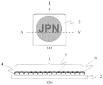
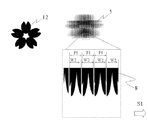
図1に、本発明の潜像印刷物(1)を示す。潜像印刷物(1)は、基材(2)上に印刷画像(3)を有して成る。基材(2)は、印刷画像(3)が形成可能な平面を備えていればよく、上質紙、コート紙、プラスティック、金属等、材質は特に限定されない。その他、基材(2)の色彩や大きさについても特に制限はない。印刷画像(3)の色彩については、透明や、不透明でも、着色されていても、いかなる色彩でも問題なく、正反射時に目視できる色彩を呈するのであればよい。ただし、第一の実施形態においては、拡散反射光下において視認できる「JPN」の文字を表して成るため、印刷画像(3)が、特定の物体色で着色されている形態として説明する。 FIG. 1 shows a latent image print (1) of the present invention. The latent image printed material (1) has a printed image (3) on a substrate (2). The base material (2) only needs to have a flat surface on which the printed image (3) can be formed, and the material is not particularly limited, such as fine paper, coated paper, plastic, metal, and the like. In addition, there is no restriction | limiting in particular also about the color and magnitude | size of a base material (2). The color of the printed image (3) may be transparent, opaque, colored, or any color as long as it presents a color that can be seen during regular reflection. However, in the first embodiment, since the characters “JPN” that can be visually recognized under diffuse reflected light are represented, the print image (3) will be described as being colored with a specific object color.
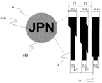
図2に印刷画像(3)の概要を示す。印刷画像(3)は、蒲鉾状要素群(4)の上に潜像要素群(5)と光反射要素群(6)が重畳して形成されて成る。正反射時に出現する有意情報は、潜像要素群(5)中に含まれる。この例において潜像要素群(5)は、第一の有意情報であるアルファベットの「A」の文字を表す第一の潜像要素群(5A)と、第二の有意情報であるアルファベットの「B」の文字を表す第二の潜像要素群(5B)から成る。 FIG. 2 shows an outline of the print image (3). The printed image (3) is formed by superimposing the latent image element group (5) and the light reflecting element group (6) on the bowl-shaped element group (4). Significant information that appears during regular reflection is included in the latent image element group (5). In this example, the latent image element group (5) includes the first latent image element group (5A) representing the letter “A” of the alphabet as the first significant information and the alphabet “ It consists of a second latent image element group (5B) representing the letter “B”.
図3に、基材(2)上に形成された蒲鉾状要素群(4)の一例を示す。蒲鉾状要素群(4)は、一定の幅(W1)の直線であり、一定の盛り上がり高さを有した蒲鉾形状を有する蒲鉾状要素(7)が、万線状に配置されて成る。本発明において、「万線状に配置する」とは、複数の要素が規則的に所定のピッチで配列されている状態をいう。より具体的には、蒲鉾状要素(7)が、画線方向と直交する第一の方向(図中S1方向)に一定のピッチ(P1)で連続して配置されて成る。なお、実施の形態において蒲鉾状要素群(4)は、盛り上がりを有した蒲鉾状の画線の集合によって構成された例について説明するが、本発明における蒲鉾状要素群(4)は、これに限定されるものではなく、盛り上がりを有した画素を要素として上下左右に等ピッチで配置して画素形態の蒲鉾状要素群(4)としてもよい。 FIG. 3 shows an example of a bowl-shaped element group (4) formed on the substrate (2). The hook-shaped element group (4) is a straight line having a constant width (W1), and the hook-shaped elements (7) having a hook shape having a constant raised height are arranged in a line. In the present invention, “arranged in a line” means a state in which a plurality of elements are regularly arranged at a predetermined pitch. More specifically, the hook-like elements (7) are continuously arranged at a constant pitch (P1) in a first direction (S1 direction in the figure) orthogonal to the image line direction. In the embodiment, the saddle-like element group (4) will be described with respect to an example in which the saddle-like element group (4) according to the present invention is configured by a collection of saddle-like drawing lines having a rise. However, the present invention is not limited to this, and a pixel-shaped saddle-like element group (4) may be formed by arranging pixels having swells at the same pitch in the vertical and horizontal directions.
蒲鉾状要素群(4)は、樹脂を含んだ材料によって構成される必要がある。ここでいう樹脂とは、ウレタン樹脂、アクリル樹脂、アルキド樹脂、エポキシ樹脂、ポリエステル樹脂、フェノール樹脂等の一般的な印刷インキのワニス成分に当たる、一定の光沢を有した樹脂を指す。透かしやエンボス等によって基材(2)に直接凹凸を形成する構成では、本発明の必須要件を満たさない。これは、基材(2)と同じ素材で構成した場合には、蒲鉾状要素群(4)の上に形成される光反射要素群(6)の反射光量を嵩上げする効果を得られないためである。また、最終的に蒲鉾状要素群(4)の反射光量は、光反射要素群(6)の反射光量を嵩上げする役目を担うため、蒲鉾状要素群(4)の反射光量が高いことが好ましい。すなわち、蒲鉾状要素群(4)の光沢は高ければ高いほど、最終的な潜像画像の視認性の高さに寄与する。 The saddle-like element group (4) needs to be made of a material containing resin. The resin here refers to a resin having a certain gloss that hits a varnish component of a general printing ink such as a urethane resin, an acrylic resin, an alkyd resin, an epoxy resin, a polyester resin, and a phenol resin. The configuration in which the unevenness is directly formed on the base material (2) by watermark or embossing does not satisfy the essential requirements of the present invention. This is because when the base material (2) is made of the same material, the effect of increasing the amount of light reflected by the light reflecting element group (6) formed on the bowl-shaped element group (4) cannot be obtained. It is. Moreover, since the amount of reflected light of the saddle-shaped element group (4) finally plays a role of increasing the amount of reflected light of the light-reflecting element group (6), it is preferable that the amount of reflected light of the bowl-shaped element group (4) is high. . That is, the higher the gloss of the bowl-shaped element group (4), the higher the visibility of the final latent image.
また、蒲鉾状要素群(4)は、明暗フリップフロップ性又はカラーフリップフロップ性の少なくとも一方の光学特性を備えていることがより好ましい。明暗フリップフロップ性とは、正反射した場合に明度が上昇する性質であり、一方のカラーフリップフロップ性とは、正反射した場合に色相が変化する性質を指す。明暗フリップフロップ性は、ワニス成分のみを印刷することでも得ることができるが、より優れた特性はアルミや真鍮、酸化鉄等の一般的な金属顔料をインキ中に配合することで容易に付与することができる。 Moreover, it is more preferable that the bowl-shaped element group (4) has at least one optical characteristic of light / dark flip-flop or color flip-flop. The light / dark flip-flop property is a property that the brightness increases when specularly reflected, and the color flip-flop property indicates a property that the hue changes when specularly reflected. Light and dark flip-flops can be obtained by printing only the varnish component, but more excellent properties can be easily imparted by blending common metal pigments such as aluminum, brass, and iron oxide into the ink. be able to.
また、カラーフリップフロップ性は、カラーフリップフロップ性を備えた機能性材料をインキ中に配合することで付与できる。カラーフリップフロップ性を備えた機能性材料の具体的な一例としては、パール顔料やコレステリック液晶、ガラスフレーク顔料、金属粉顔料や鱗ペン状金属顔料等がある。また、当然のことながら機能性材料をインキに配合するだけでなく、明暗フリップフロップ性やカラーフリップフロップ性を有するインキとして市販されているインキを用いて光反射要素群(6)を形成してもよい。 Further, the color flip-flop property can be imparted by blending a functional material having the color flip-flop property into the ink. Specific examples of functional materials having color flip-flop properties include pearl pigments, cholesteric liquid crystals, glass flake pigments, metal powder pigments, and scale pen-like metal pigments. Naturally, not only the functional material is blended into the ink, but also the light reflecting element group (6) is formed using an ink marketed as an ink having a light / dark flip-flop property and a color flip-flop property. Also good.
明暗フリップフロップ性を有する市販インキとしては、金インキや銀インキ、樹脂自体の光沢が高いOPニス、グロスニス等が存在し、カラーフリップフロップ性を有する市販インキとしては、CSI(Color Shifting Ink)やOVI(Optical Variable Ink)、液晶インキ等がある。 Commercially available inks having light and dark flip-flop properties include gold ink and silver ink, OP varnish and gloss varnish having high gloss of the resin itself, and commercially available inks having color flip-flop properties include CSI (Color Shifting Ink) and There are OVI (Optical Variable Ink), liquid crystal ink, and the like.
蒲鉾状要素群(4)が高い明暗フリップフロップ性のみを備える場合、光反射要素群(6)の構成にもよるが、正反射光下で出現するモアレ模様の視認性が向上する傾向にあり、高いカラーフリップフロップ性を備える場合には、モアレ模様はより色彩豊かな表現が可能となる。 When the bowl-shaped element group (4) has only a high brightness / darkness flip-flop property, the visibility of the moire pattern that appears under specular reflection light tends to improve, although it depends on the configuration of the light reflecting element group (6). In the case of having a high color flip-flop property, the moiré pattern can express more colorful.
一般にUV硬化型のスクリーン印刷によって蒲鉾状要素群(4)を形成する場合、スクリーンインキの粘度が高い方が、蒲鉾状要素(7)の盛り上がり高さは高く、かつ、それぞれの蒲鉾状要素(7)の三次元立体形状は、互いに均一になる傾向にある。このような蒲鉾状要素(7)の均一な構造は、潜像の視認性や鮮明さを高めるためには極めて好ましいことから、本発明の蒲鉾状要素群(4)を形成するに当たっては、粘度の高いインキを用いることが好ましい。以上が、蒲鉾状要素群(4)の説明である。 In general, when the ridge-like element group (4) is formed by UV curable screen printing, the higher the viscosity of the screen ink, the higher the height of the ridge-like element (7), and each ridge-like element ( The three-dimensional solid shape of 7) tends to be uniform with each other. Such a uniform structure of the saddle-like element (7) is extremely preferable for enhancing the visibility and clarity of the latent image. Therefore, in forming the saddle-like element group (4) of the present invention, the viscosity It is preferable to use a high ink. The above is the description of the bowl-shaped element group (4).
続いて、潜像要素群(5)について図4を用いて説明する。潜像要素群(5)は、正反射時に出現する潜像の基となる複数の有意情報を含んで成る。本実施の形態の例では、第一の有意情報である「A」の文字と、第二の有意情報である「B」の文字の二つの有意情報を含んでいる。それぞれの有意情報を表した画像をそれぞれ基画像と呼ぶ。本実施の形態においては、「A」の文字を第一の基画像とし、「B」の文字を第二の基画像とする。 Next, the latent image element group (5) will be described with reference to FIG. The latent image element group (5) includes a plurality of pieces of significant information that is the basis of the latent image that appears during regular reflection. The example of the present embodiment includes two pieces of significant information, that is, the letter “A” as the first significant information and the letter “B” as the second significant information. Each image representing the significant information is called a base image. In the present embodiment, the character “A” is the first base image, and the character “B” is the second base image.
本実施の形態において、第一の基画像が表す第一の有意情報は、図4(b)に示す第一の潜像要素群(5A)によって形成され、第二の基画像が表す第二の有意情報は、図4(c)に示す第二の潜像要素群(5B)によって形成される。第一の潜像要素群(5A)は、一定の画線幅(W2)の第一の潜像要素(8A)が、蒲鉾状要素群(4)と同じ第一の方向(S1)に、同じピッチ(P1)で、万線状に連続して配置されて成り、第二の潜像要素群(5B)は、一定の画線幅(W3)の第二の潜像要素(8B)が、蒲鉾状要素群(4)と同じ第一の方向(S1)に、同じピッチ(P1)で、万線状に連続して配置されて成る。第一の潜像要素(8A)の画線幅(W2)は全て同じであり、第二の潜像要素(8B)の画線幅(W3)も全て同じである必要があるが、第一の潜像要素(8A)の画線幅(W2)と第二の潜像要素(8B)の画線幅(W3)の値は同じであってもよいし、異なっていてもよい。 In the present embodiment, the first significant information represented by the first base image is formed by the first latent image element group (5A) shown in FIG. 4B, and the second significant image represented by the second base image. Is formed by the second latent image element group (5B) shown in FIG. In the first latent image element group (5A), the first latent image element (8A) having a constant image line width (W2) is in the same first direction (S1) as the bowl-shaped element group (4). The second latent image element group (5B) is continuously arranged in the shape of a line at the same pitch (P1), and the second latent image element (8B) having a constant line width (W3) is included in the second latent image element group (5B). In the same first direction (S1) as the saddle-like element group (4), the same pitch (P1) is continuously arranged in a line shape. The first latent image element (8A) has the same line width (W2), and the second latent image element (8B) must have the same line width (W3). The image line width (W2) of the latent image element (8A) and the image line width (W3) of the second latent image element (8B) may be the same or different.
ここで、それぞれの第一の潜像要素(8A)と第二の潜像要素(8B)の位置関係について説明する。第一の潜像要素(8A)と第二の潜像要素(8B)は重なり合ってはならない。具体的には、第一の潜像要素(8A)と第二の潜像要素(8B)は、第一の方向(S1)に位相がずれている必要がある。図4(a)は、その一例として、ピッチ(P1)の半分(2分の1)ずれて配置された状態を示している。仮に、第一の潜像要素(8A)と第二の潜像要素(8B)が重なり合って配置された場合には、正反射光下の特定の観察角度において、第一の有意情報と第二の有意情報が重なり合った不明瞭な画像が出現するため、そのような構成は避けなければならない。なお、以降の説明では、具体的に個別の潜像要素(8A、8B)を指すのではなく、潜像要素全般を指す場合には、潜像要素(8)として説明する。 Here, the positional relationship between each first latent image element (8A) and the second latent image element (8B) will be described. The first latent image element (8A) and the second latent image element (8B) must not overlap. Specifically, the first latent image element (8A) and the second latent image element (8B) need to be out of phase in the first direction (S1). FIG. 4A shows, as an example, a state in which the pitch (P1) is shifted by half (1/2). If the first latent image element (8A) and the second latent image element (8B) are arranged so as to overlap each other, the first significant information and the second significant information are obtained at a specific observation angle under specular reflection light. Such an arrangement must be avoided because an indistinct image appears in which significant information overlaps. In the following description, when referring to the entire latent image element rather than specifically referring to the individual latent image elements (8A, 8B), the latent image element (8) will be described.
以上のように、製作者が正反射光下で潜像として出現させたいと意図する情報(画像)が基画像であり、基画像を本技術の構成に合わせて分断及び/又は圧縮等の処理(圧縮等の処理については後述する。)を施した画像が潜像要素群(5)であり、潜像要素群(5)を構成している一つ一つの要素が潜像要素(8)である。 As described above, information (image) that the producer intends to appear as a latent image under specular reflection light is the base image, and the base image is processed according to the configuration of the present technology, such as segmentation and / or compression. (The processing such as compression will be described later) is the latent image element group (5), and each element constituting the latent image element group (5) is the latent image element (8). It is.
潜像要素群(5)を構成するそれぞれの潜像要素(8)の拡散反射光下の色彩は、透明であっても半透明であってもよく、着色されていてもよい。第一の実施形態においては、潜像要素群(5)が透明又は半透明である形態について説明する。潜像要素群(5)が着色されている形態については、第二の実施形態で説明する。なお、第一の実施形態においては、潜像要素群(5)が画線である形態で説明するが、これに限定されるものではなく、仮に蒲鉾状要素群(4)を画素形態とした場合には、潜像要素群(5)も画線ではなく、対応した画素形態とすることが好ましい。 The color under diffuse reflection of each latent image element (8) constituting the latent image element group (5) may be transparent, translucent, or colored. In the first embodiment, a mode in which the latent image element group (5) is transparent or translucent will be described. The form in which the latent image element group (5) is colored will be described in the second embodiment. In the first embodiment, the latent image element group (5) is described as an image line. However, the present invention is not limited to this, and the saddle-shaped element group (4) is assumed to be a pixel form. In this case, it is preferable that the latent image element group (5) is not an image line but a corresponding pixel form.
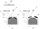
潜像要素群(5)に要求される光学特性は、印刷画像(3)の層構造によって変化する。図5(a)に示すように、印刷画像(3)の層構造が蒲鉾状要素群(4)の上に潜像要素群(5)が重なり、その上に光反射要素群(6)が重なるような層構造の場合には、正反射光下で出現する基画像(12)の視認性を高くするために、蒲鉾状要素(7)と潜像要素(8)はその表面性が大きく異なっていることが好ましい。このため、蒲鉾状要素(7)と潜像要素(8)は、可能な限り大きな表面性の違いが生じるように設計する。なお、本発明における「表面性」とは、各要素を構成したインキの表面の滑らかさのことをいう。 The optical characteristics required for the latent image element group (5) vary depending on the layer structure of the printed image (3). As shown in FIG. 5 (a), the layer structure of the printed image (3) is such that the latent image element group (5) is superimposed on the bowl-shaped element group (4), and the light reflecting element group (6) is formed thereon. In the case of overlapping layer structures, in order to increase the visibility of the base image (12) appearing under specular reflection light, the saddle-like element (7) and the latent image element (8) have a large surface property. Preferably they are different. For this reason, the saddle-like element (7) and the latent image element (8) are designed so that the difference in surface properties is as great as possible. The “surface property” in the present invention refers to the smoothness of the surface of the ink constituting each element.
その理由を以下に記す。蒲鉾状要素(7)の上に潜像要素(8)が重なり、更にその上に光反射要素群(6)が重なる場合、光反射要素群(6)は、蒲鉾状要素(7)と比較すると薄い膜厚であることから、蒲鉾状要素(7)と潜像要素(8)の表面性の違いが光反射要素群(6)に反映される。すなわち、滑らかな蒲鉾状要素(7)の上に重なった光反射要素群(6)は、その表面が相対的に滑らかであり、粗い潜像要素(8)の上に重なった光反射要素群(6)は、その表面が相対的に粗くなる。基本的には蒲鉾状要素(7)と潜像要素(8)の表面性の違いが、光反射要素群(6)の表面性の違いとして相対的に反映され、その違いが基画像(12)の視認性へと直結する。逆に、その表面性の差異が小さい場合には、光反射要素群(6)の膜厚によって埋められてしまい、光反射要素群(6)表面にその表面性の差異が反映されず、正反射光下で出現する基画像(12)の視認性が低くなる。 The reason is described below. When the latent image element (8) is superimposed on the bowl-shaped element (7) and the light-reflecting element group (6) is further superimposed thereon, the light-reflecting element group (6) is compared with the bowl-shaped element (7). Then, since it is a thin film thickness, the difference in surface property between the bowl-shaped element (7) and the latent image element (8) is reflected in the light reflecting element group (6). That is, the light reflecting element group (6) superimposed on the smooth bowl-shaped element (7) has a relatively smooth surface and the light reflecting element group superimposed on the rough latent image element (8). (6) has a relatively rough surface. Basically, the difference in surface property between the saddle-shaped element (7) and the latent image element (8) is relatively reflected as the difference in surface property of the light reflecting element group (6). ) Direct visibility. Conversely, when the difference in surface property is small, it is filled with the film thickness of the light reflecting element group (6), and the difference in surface property is not reflected on the surface of the light reflecting element group (6). The visibility of the base image (12) appearing under reflected light is lowered.
以上のことから、図5(a)に示すような蒲鉾状要素群(4)の上に潜像要素群(5)が重なり、その上に光反射要素群(6)が重なるような層構造の場合には、正反射光下で出現する基画像(12)の視認性を高くするために、蒲鉾状要素(7)と潜像要素(8)は、その表面性が大きく異なっていることが好ましい。なお、光反射要素群(6)の表面性の差異は、僅かながら光反射要素群(6)の印刷膜厚で埋められるため、もともとの蒲鉾状要素(7)と潜像要素(8)との表面性の差異から僅かながら小さくなる。これを見越して、可能な限り表面性の差異を大きくすることが好ましい。 From the above, a layer structure in which the latent image element group (5) overlaps the bowl-shaped element group (4) as shown in FIG. 5A and the light reflecting element group (6) overlaps thereon. In the case of (2), in order to increase the visibility of the base image (12) appearing under specular reflection light, the surface properties of the bowl-shaped element (7) and the latent image element (8) are greatly different. Is preferred. In addition, since the difference in surface property of the light reflecting element group (6) is slightly filled with the printed film thickness of the light reflecting element group (6), the original bowl-shaped element (7) and the latent image element (8) Slightly smaller due to the difference in surface properties. In view of this, it is preferable to increase the surface property difference as much as possible.
表面性の差異の具体的な範囲については、微細な領域の表面性の違いを容易に測定できる数値で表すことは困難であることから、表面性と相関の高い数値である、正反射時の明度の差に換算して示すと、蒲鉾状要素(7)と潜像要素(8)の間には少なくとも明度L*が10以上の明度差が必要である。多くの場合、蒲鉾状要素(7)は、高光沢な構成となることから、潜像要素(8)は逆に低光沢であることが好ましい。すなわち、蒲鉾状要素(7)の明度が高く、潜像要素(8)の明度が低い構成とすることが好ましい。なお、明度差L*が10に満たない場合、潜像が不鮮明となるため避けなければならない。 The specific range of the surface property difference is difficult to express with a numerical value that can easily measure the surface property difference of a fine region. In terms of brightness difference, a brightness difference of at least a brightness L * of 10 or more is required between the bowl-shaped element (7) and the latent image element (8). In many cases, the saddle-like element (7) has a high-gloss structure, so that the latent image element (8) is preferably low-gloss. That is, it is preferable that the brightness of the bowl-shaped element (7) is high and the brightness of the latent image element (8) is low. If the lightness difference L * is less than 10, the latent image becomes unclear and must be avoided.
また、図5(b)のように、印刷画像(3)の層構造が蒲鉾状要素群(4)の上に光反射要素群(6)が重なり、更にその上に潜像要素群(5)が重なるような層構造の場合には、正反射光下で出現する基画像(12)の視認性を高くするために、蒲鉾状要素(7)と潜像要素(8)は、正反射時の色彩が大きく異なっていることが好ましい。具体的には蒲鉾状要素(7)と潜像要素(8)は、正反射時の色差ΔEが10以上異なっている必要がある。色差ΔEが10に満たない場合、光反射要素群(6)と潜像要素群(5)の色差が小さく、潜像画像が不明瞭となる場合があるため避けなければならない。この層構造の場合、潜像要素群(5)は明暗フリップフロップ性又はカラーフリップフロップ性を備えていてもよく、この場合にはより豊かな色彩表現が可能となる。 Further, as shown in FIG. 5B, the layer structure of the printed image (3) has a light-reflecting element group (6) overlaid on the bowl-shaped element group (4), and further a latent image element group (5 In the case of a layer structure in which) overlaps, the saddle-like element (7) and the latent image element (8) are specularly reflected in order to increase the visibility of the base image (12) that appears under specular reflection light. It is preferable that the time colors are greatly different. Specifically, the saddle-like element (7) and the latent image element (8) need to have a color difference ΔE of 10 or more different during regular reflection. When the color difference ΔE is less than 10, the color difference between the light reflecting element group (6) and the latent image element group (5) is small, and the latent image may be unclear. In the case of this layer structure, the latent image element group (5) may be provided with a light / dark flip-flop property or a color flip-flop property, and in this case, a richer color expression is possible.
以上のように、印刷画像(3)の層構造によって、潜像要素群(5)に要求される光学特性が変化する。なお、潜像要素群(5)が着色されて形成される形態において潜像要素群(5)に要求される光学特性については、第二の実施形態で説明する。また、潜像要素群(5)の画線構成によって、正反射光下において基画像(12)が異なる別の基画像(12)へとチェンジするだけでなく、出現した基画像(12)が動いて見える動画効果を生じさせる形態も存在し、これら動画効果を生じさせる潜像要素群(5)の構成についても後述する。以上が潜像要素群(5)の説明である。 As described above, the optical characteristics required for the latent image element group (5) vary depending on the layer structure of the printed image (3). Note that optical characteristics required for the latent image element group (5) in the form in which the latent image element group (5) is colored will be described in the second embodiment. Further, depending on the image line configuration of the latent image element group (5), not only the base image (12) is changed to a different base image (12) under specular reflection light, but also the appeared base image (12) is displayed. There are also forms that produce moving image effects that appear to move, and the configuration of the latent image element group (5) that produces these moving image effects will also be described later. The above is the description of the latent image element group (5).
次に光反射要素群(6)について説明する。蒲鉾状要素群(4)の上に形成される光反射要素群(6)とは、蒲鉾状要素群(4)の上に重ねて形成されることで、印刷画像(3)から著しく強い正反射光を生じさせる働きを成す、光反射特性に優れた印刷層である。 Next, the light reflecting element group (6) will be described. The light reflecting element group (6) formed on the saddle-shaped element group (4) is formed so as to be superimposed on the saddle-shaped element group (4), so that a significantly strong positive image can be obtained from the printed image (3). It is a printed layer that has a function of generating reflected light and has excellent light reflection characteristics.
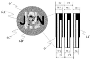
図6に示すように第一の実施形態においては、拡散反射光下において視認可能な有意情報(以下「可視画像」という。)の「JPN」の文字を表した情報部(6A)と、その背景を成す背景部(6B)から成る。情報部(6A)と背景部(6B)は、少なくとも一部の領域が画線の太細によって区分けされなければならない。第一の実施形態の例においては、情報部(6A)の全ての領域が太い画線幅(W4)の光反射要素(9)が万線状に連続して配置され、背景部(6B)の全ての領域は、細い画線幅(W5)の光反射要素(9)が万線状に連続して配置されることで、画線面積率の差異によって光反射要素群(6)の中に特定の有意情報を表して成る。 As shown in FIG. 6, in the first embodiment, an information part (6A) representing characters “JPN” of significant information (hereinafter referred to as “visible image”) visible under diffuse reflected light, It consists of a background part (6B) that forms the background. The information part (6A) and the background part (6B) must be separated at least in part by the thickness of the image line. In the example of the first embodiment, the light reflecting elements (9) having a thick line width (W4) are continuously arranged in a line in the entire area of the information portion (6A), and the background portion (6B). In all the regions of FIG. 4, the light reflecting elements (9) having a narrow line width (W5) are continuously arranged in a line shape, so that the light reflecting element group (6) has a difference in the line area ratio. It represents specific significant information.
なお、第一の実施形態では情報部(6A)を太い画線幅で、背景部(6B)を細い画線幅で構成しているが、情報部(6A)を細い画線幅(W5)で、背景部(6B)を太い画線幅(W4)で構成しても問題ない。なお、第一の実施形態においては、光反射要素群(6)が画線である形態で説明するが、これに限定されるものではなく、仮に蒲鉾状要素群(4)を画素形態とした場合には、光反射要素群(6)も画線ではなく、対応した画素形態とすることが好ましい。 In the first embodiment, the information portion (6A) has a thick line width and the background portion (6B) has a thin line width. However, the information portion (6A) has a thin line width (W5). Thus, there is no problem even if the background portion (6B) is configured with a thick line width (W4). In the first embodiment, the light reflection element group (6) is described as an image line. However, the present invention is not limited to this, and the bowl-shaped element group (4) is assumed to be a pixel form. In this case, it is preferable that the light reflecting element group (6) is not an image line but a corresponding pixel form.
第一の実施形態においては、光反射要素群(6)は、第一の方向(S1)に第一のピッチ(P1)と異なる第二のピッチ(P2)で万線状に連続して配置して成るが、方向、ピッチ及び形状の少なくとも一つが蒲鉾状要素群(4)と異なっていればよい。これは、光反射要素群(6)と蒲鉾状要素群(4)とを干渉させてモアレ模様(m)を生じさせるための必須要件である。仮にピッチのみを異ならせる場合には、第二のピッチ(P2)は、第一のピッチ(P1)に対して80%〜120%程度の値とすることが好ましく、仮に方向のみを変えるのであれば、第二の方向(S2)は、第一の方向(S1)に対してプラスマイナス10度以下の角度とすることが好ましい。この範囲外の数値の場合、モアレ模様(m)が発生しないか、生じたモアレ模様(m)の動きが小さく、適さない。基本的には、全ての蒲鉾状要素(7)上に少なくとも一つ光反射要素(9)が重なるように形成する。 In the first embodiment, the light reflecting element group (6) is continuously arranged in a single line at a second pitch (P2) different from the first pitch (P1) in the first direction (S1). However, it is sufficient that at least one of the direction, the pitch, and the shape is different from that of the bowl-shaped element group (4). This is an essential requirement for causing the moire pattern (m) by causing the light-reflecting element group (6) and the hook-shaped element group (4) to interfere with each other. If only the pitch is changed, the second pitch (P2) is preferably set to a value of about 80% to 120% with respect to the first pitch (P1), and only the direction is changed. For example, the second direction (S2) is preferably an angle of plus or minus 10 degrees or less with respect to the first direction (S1). In the case of a numerical value outside this range, the moire pattern (m) does not occur or the generated moire pattern (m) has a small movement and is not suitable. Basically, at least one light-reflecting element (9) is formed so as to overlap all of the bowl-shaped elements (7).
また、形状を異ならせる場合には、「モアレ拡大現象(Moire Magnification)」と呼ばれる現象によって、光反射要素群(6)の形状が出現するモアレの形状に反映される。仮に、蒲鉾状要素群(4)が画素の場合に「Moire Magnification」を用いて特定の形状のモアレを出現させるには、特許第3338860号公報等に記載の構成を光反射要素群(6)に適用すればよい。また、蒲鉾状要素群(4)が画線の場合には、特許第4427796号公報や特許第5131789号公報等に記載の構成を光反射要素群(6)に適用すればよい。ただし、本発明は、印刷によって形成することを前提としていることから、高い解像度を要求する形状とすることは避けることが望ましい。蒲鉾状要素群(4)が画線の場合には、光反射要素群(6)には曲線や波線等の単純な形状の画線を適用することが望ましい。いずれの場合であっても、基本的には、全ての蒲鉾状要素(7)上に、少なくとも一つ光反射要素(9)が重なるように形成する。 Also, when the shapes are different, the shape of the light reflecting element group (6) is reflected in the shape of the moire where the shape of the light reflecting element group (6) appears due to a phenomenon called “moire enlargement phenomenon”. If the moiré-shaped element group (4) is a pixel and the moire having a specific shape is caused to appear by using “Moire Magication”, the configuration described in Japanese Patent No. 3338860 is used as the light-reflecting element group (6). Apply to the above. In addition, when the saddle-shaped element group (4) is an image line, the configuration described in Japanese Patent No. 4427796 and Japanese Patent No. 5131789 may be applied to the light reflecting element group (6). However, since the present invention is premised on forming by printing, it is desirable to avoid a shape that requires high resolution. When the saddle-shaped element group (4) is an image line, it is desirable to apply an image line having a simple shape such as a curve or a wavy line to the light reflecting element group (6). In any case, basically, at least one light reflecting element (9) is formed so as to overlap all of the bowl-shaped elements (7).
第一の実施形態のように、画線の太細によって可視画像を表している場合には、物体色を有している必要があるが、可視画像を表さない形態においては、特に光反射要素群(6)は、透明や半透明であってもよい。 As in the first embodiment, when a visible image is represented by a thin line, it is necessary to have an object color. However, in a form that does not represent a visible image, light reflection is particularly required. The element group (6) may be transparent or translucent.
また、光反射要素群(6)は、明暗フリップフロップ性又はカラーフリップフロップ性の少なくとも一方の光学特性を有する必要があり、加えて光反射要素群(6)の正反射時の色彩は、蒲鉾状要素群(4)の正反射時の色彩と異なっている必要がある。より具体的には、蒲鉾状要素群(4)の正反射時の色彩よりも明るい色彩か、あるいは色相が異なる色彩である必要がある。これは、正反射光下で蒲鉾状要素群(4)と光反射要素群(6)とが干渉することで出現するモアレ模様(m)を、基画像(12)の視認性を損なわずに可視化するために必要な条件である。なお、仮に光反射要素群(6)が透明であっても、不透明であっても本発明の効果を得ることができる。 In addition, the light reflecting element group (6) needs to have at least one optical characteristic of light / dark flip-flop property or color flip-flop property. In addition, the color of the light reflecting element group (6) during regular reflection is It must be different from the color of regular element group (4) during regular reflection. More specifically, it is necessary that the color is brighter than the color at the time of regular reflection of the bowl-shaped element group (4) or the color is different in hue. This is because the moire pattern (m) that appears when the saddle-shaped element group (4) and the light-reflecting element group (6) interfere with each other under regular reflection light without impairing the visibility of the base image (12). This is a necessary condition for visualization. Even if the light reflecting element group (6) is transparent or opaque, the effects of the present invention can be obtained.
ただし、光反射要素群(6)が透明な場合、入射する光を反射する画線表面が光反射要素群(6)と蒲鉾状要素(7)の二つの面となる。反射面が二つ存在する場合、この反射面の距離の差(光反射要素群(6)の厚み)が1μm以下であっても、潜像の鮮明さに影響を与えるため、潜像は不鮮明になる場合がある。このため、本発明の潜像印刷物(1)において、潜像を鮮明に出現させることを意図する場合には、光反射要素群(6)を不透明とすることがより好ましい。 However, when the light reflecting element group (6) is transparent, the surface of the image line that reflects the incident light becomes the two surfaces of the light reflecting element group (6) and the bowl-shaped element (7). When there are two reflecting surfaces, the latent image is unclear because the difference in the distance between the reflecting surfaces (the thickness of the light reflecting element group (6)) is 1 μm or less, which affects the clarity of the latent image. It may become. For this reason, in the latent image printed material (1) of the present invention, when the latent image is intended to appear clearly, it is more preferable that the light reflecting element group (6) is opaque.
光反射要素群(6)は、図5(a)、図5(b)のいずれの層構造の形態であっても、先に印刷されて、既に硬化した蒲鉾状要素群(4)より上に形成される。光反射要素群(6)は、光反射要素(9)が特定のピッチで複数配置されて形成された構造を有し、基本的には、全ての蒲鉾状要素(7)上に少なくとも一つの光反射要素(9)が重なって形成される。 The light-reflecting element group (6) is in the form of any of the layer structures of FIG. 5 (a) and FIG. Formed. The light reflecting element group (6) has a structure in which a plurality of light reflecting elements (9) are arranged at a specific pitch. Basically, at least one light reflecting element group (7) is provided on all the bowl-shaped elements (7). Light reflecting elements (9) are formed to overlap.
図5(a)の形態の場合、断面構造は、図7(a)に示すように蒲鉾状要素(7)の上に潜像要素(8A、8B)が重なり、更に光反射要素群(6)が重なって形成される。蒲鉾状要素(7)と潜像要素(8A、8B)の表面性は異なっており、一定膜厚のインキ層から成る光反射要素群(6)がその上に重ねられて形成された場合、その表面性の差異は、光反射要素群(6)のインキ層によって埋められて僅かに小さくなるものの、光反射要素群(6)の表面性の違いとして反映される。そのため、光反射要素群(6)の表面に光が入射した際、仮にその光反射要素群(6)の下に蒲鉾状要素(7)が存在する場合、反射光量は大きくなり、光反射要素群(6)の下に潜像要素(8)が存在する場合、反射光量は小さくなる。すなわち、図5(a)のように、蒲鉾状要素(7)と潜像要素(8A、B)の上に光反射要素群(6)が重なった場合でも、正反射光下においては、蒲鉾状要素(7)と潜像要素(8A、8B)の表面性の違いが光反射要素群(6)から生じる反射光量の大小として反映される。 In the case of the form of FIG. 5A, the cross-sectional structure is such that the latent image elements (8A, 8B) are superimposed on the bowl-shaped element (7) as shown in FIG. ) Overlap. The surface properties of the saddle-like element (7) and the latent image element (8A, 8B) are different, and when the light-reflecting element group (6) consisting of an ink layer having a constant film thickness is formed on top of it, The difference in surface property is reflected as a difference in surface property of the light reflecting element group (6) although it is slightly reduced by being filled with the ink layer of the light reflecting element group (6). Therefore, when light is incident on the surface of the light reflecting element group (6), if the bowl-shaped element (7) exists under the light reflecting element group (6), the amount of reflected light increases, and the light reflecting element When the latent image element (8) is present under the group (6), the amount of reflected light is small. That is, as shown in FIG. 5 (a), even when the light reflecting element group (6) overlaps the saddle-shaped element (7) and the latent image elements (8A, B), The difference in surface properties between the shape element (7) and the latent image elements (8A, 8B) is reflected as the amount of reflected light generated from the light reflecting element group (6).
また、蒲鉾状要素(7)に直接光反射要素群(6)が重なった領域は、土台となる蒲鉾状要素(7)の盛り上がりの高さや幅のような大まかな立体構造はそのまま反映されるが、一方で蒲鉾状要素(7)の画線表面の僅かな凹凸は光反射要素群(6)の膜厚によって印刷直後にある程度平坦に埋められる。このため、蒲鉾状要素(7)に光反射要素群(6)が重なった場合の表面は、元の蒲鉾状要素(7)の表面よりも滑らかになって反射光量も大きくなり、結果として正反射光下で出現する基画像(12)の鮮明さが向上することとなる。 In the region where the light reflecting element group (6) directly overlaps the bowl-shaped element (7), the rough three-dimensional structure such as the height and width of the foundation-shaped bowl-shaped element (7) is reflected as it is. However, on the other hand, the slight unevenness on the surface of the image line of the saddle-like element (7) is buried to some extent immediately after printing by the film thickness of the light reflecting element group (6). For this reason, the surface when the light-reflecting element group (6) overlaps the bowl-shaped element (7) is smoother than the surface of the original bowl-shaped element (7), and the amount of reflected light is larger. The sharpness of the base image (12) appearing under the reflected light will be improved.
一方、図5(b)の形態の場合、断面構造は、図7(b)に示すように蒲鉾状要素(7)の上に光反射要素群(6)が重なり、更に潜像要素(8A、8B)が重なって形成される。この形態においては、図5(a)の形態と同様に土台となる蒲鉾状要素(7)の盛り上がりの高さや幅のような大まかな立体構造はそのまま反映され、一方で蒲鉾状要素(7)の画線表面の僅かな凹凸は、光反射要素群(6)の膜厚によって平坦に埋められ、元の蒲鉾状要素(7)の表面よりも滑らかになり、反射光量も大きくなる。光反射要素群(6)の上に潜像要素(8A、8B)が重なった領域は、その下の光反射要素群(6)へ達する入射光を遮ることで、生じる反射光量が著しく低下する。以上のように、正反射光下においては潜像要素(8A、8B)の有無が、反射光量の大小として反映される。 On the other hand, in the case of the form of FIG. 5 (b), the cross-sectional structure is such that the light reflecting element group (6) overlaps the bowl-shaped element (7) as shown in FIG. 8B) are overlapped. In this embodiment, as in the embodiment of FIG. 5A, the rough three-dimensional structure such as the height and width of the ridge-like element (7) as a base is reflected as it is, while the ridge-like element (7). The slight unevenness on the surface of the image line is filled with the film thickness of the light reflecting element group (6), becomes smoother than the surface of the original bowl-shaped element (7), and the amount of reflected light also increases. In the region where the latent image elements (8A, 8B) overlap the light reflecting element group (6), the amount of reflected light is significantly reduced by blocking incident light reaching the light reflecting element group (6) below the area. . As described above, the presence or absence of the latent image elements (8A, 8B) is reflected as the magnitude of the reflected light amount under the regular reflection light.
なお、図5(a)、図5(b)のいずれの層構造の形態であっても、光反射要素群(6)は、蒲鉾状要素(7)上にのみ形成される必要はなく、蒲鉾状要素(7)と蒲鉾状要素(7)の間の非画線部に形成されてもよい。 Note that the light reflecting element group (6) does not have to be formed only on the bowl-shaped element (7) in any of the layer structures of FIGS. 5 (a) and 5 (b). It may be formed in a non-image portion between the hook-shaped element (7) and the hook-shaped element (7).
以上、説明したとおり、本発明の潜像印刷物(1)において、蒲鉾状要素(7)の上に光反射要素群(6)を形成することで、基画像(12)の視認性を損なわないモアレ模様(m)を出現させることができ、かつ、光反射要素群(6)を不透明とした場合には、反射光を画線表面由来の光のみとすることができ、基画像(12)の鮮明さが向上する。 As described above, in the latent image printed material (1) of the present invention, the visibility of the base image (12) is not impaired by forming the light reflecting element group (6) on the bowl-shaped element (7). When the moiré pattern (m) can appear and the light reflecting element group (6) is opaque, the reflected light can be only light derived from the surface of the image line, and the base image (12) Improves sharpness.
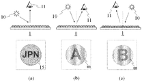
本発明の潜像印刷物(1)の効果について、図8を用いて説明する。まず、潜像印刷物(1)を、図8(a)に示すように拡散反射光下で観察した場合、第一の実施形態においては、可視画像(15)の「JPN」の文字のみが視認される。拡散反射光下においては、基画像(12)やモアレ模様(m)は出現せず、完全に不可視である。 The effect of the latent image printed material (1) of the present invention will be described with reference to FIG. First, when the latent image print (1) is observed under diffuse reflected light as shown in FIG. 8A, only the characters “JPN” in the visible image (15) are visible in the first embodiment. Is done. Under diffuse reflection, the base image (12) and the moire pattern (m) do not appear and are completely invisible.
続いて、正反射光下の効果について説明する。正反射光下においては、まず、拡散反射光下で視認されていた可視画像(15)の「JPN」は、目視上消失する。これは、光反射要素群(6)が正反射することで画像全体の濃度が淡くなり(明度が上昇し)、「JPN」の文字とその周辺の濃度差(明度差)が圧縮されて小さくなり、目視上捉えられなくなるためである。 Next, the effect under regular reflection light will be described. Under regular reflection light, first, “JPN” of the visible image (15) visually recognized under diffuse reflection light disappears visually. This is because the light reflection element group (6) is regularly reflected, so that the density of the entire image becomes light (the brightness increases), and the density difference between the characters “JPN” and the surrounding area (lightness difference) is compressed and reduced. This is because it cannot be caught visually.
また、図8(b)のように、左側にある光源(10)から潜像印刷物(1)に光が入射した場合、観察者(11)には、第一の有意情報であるアルファベットの「A」(第一の基画像(12A))と、「A」とは異なる色彩を有したモアレ模様(m)が視認される。一方、図8(c)のように、右側から潜像印刷物(1)に光が入射した場合、観察者(11)には、第二の有意情報であるアルファベットの「B」(第二の基画像(12B))と、「B」とは異なる色彩を有したモアレ模様(m)が視認される。また、背景に出現するモアレ模様(m)は、図9に示すように、潜像印刷物(1)の傾きを変えることで左右(図中⇔方向)に連続的に動いて見える。実際には、入射する光の角度の変化に応じて、印刷画像(3)中に視認される有意情報がチェンジする効果と、モアレ模様(m)が動いて見える効果が同時に発現する。また、チェンジする有意情報と、モアレ模様(m)の色彩が異なっているため、それぞれの視認性は損なわれない。 Further, as shown in FIG. 8B, when light is incident on the latent image printed matter (1) from the light source (10) on the left side, the alphabet (1), which is the first significant information, is displayed to the observer (11). A ”(first base image (12A)) and a moire pattern (m) having a color different from“ A ”are visually recognized. On the other hand, as shown in FIG. 8C, when light is incident on the latent image printed material (1) from the right side, the observer (11) has the alphabet “B” (second significant information) as the second significant information. The base image (12B)) and the moire pattern (m) having a color different from “B” are visually recognized. Further, as shown in FIG. 9, the moire pattern (m) appearing in the background appears to move continuously from side to side (in the vertical direction in the figure) by changing the inclination of the latent image print (1). Actually, the effect that the significant information visually recognized in the printed image (3) changes in accordance with the change in the angle of the incident light and the effect that the moire pattern (m) appears to move simultaneously appear. Moreover, since the significant information to change and the color of a moire pattern (m) differ, each visibility is not impaired.
以上のような効果を生じる理由について説明する。基画像(12)がチェンジする効果と、モアレ模様(m)が動く効果のうち、まず、基画像(12)がチェンジする効果について説明する。図8(b)に示すように、左側から潜像印刷物(1)に光が入射した場合、光反射要素群(6)は、盛り上がりを有する蒲鉾状要素(7)上に形成されて成るため、入射した光と法線を成す面のみを中心に光を強く反射する。光反射要素群(6)は、光反射要素(9)が特定のピッチで複数配置されて形成された構造を有し、全ての蒲鉾状要素(7)上に少なくとも一つ光反射要素(9)が重なって形成される。このため、光反射要素群(6)の画線表面のうち、盛り上がりの中心より左側は光を強く反射して色彩が変化する。 The reason why the above effects are produced will be described. Of the effect of changing the base image (12) and the effect of moving the moire pattern (m), the effect of changing the base image (12) will be described first. As shown in FIG. 8B, when light is incident on the latent image printed material (1) from the left side, the light reflecting element group (6) is formed on the ridge-shaped element (7) having a bulge. , The light is strongly reflected around only the surface normal to the incident light. The light reflecting element group (6) has a structure in which a plurality of light reflecting elements (9) are arranged at a specific pitch, and at least one light reflecting element (9) is formed on all the bowl-shaped elements (7). ) Overlap. For this reason, on the left side from the center of the rise in the image surface of the light reflecting element group (6), the light is strongly reflected and the color changes.
光反射要素群(6)の左側には、通常の観察条件では不可視であるが、蒲鉾状要素(7)とは表面性や正反射時の明度が異なる材料で形成された第一の潜像要素(8A)が重なって形成されており、反射光の色彩の違いによって、第一の潜像要素(8A)が周囲とは異なる色彩で可視化される。この場合、光反射要素群(6)の表面のそれぞれの盛り上がりにある、全ての第一の潜像要素(8A)が一度に可視化されるため、結果として第一の潜像要素群(5A)が表す第一の有意情報の「A」(第一の基画像(12A))が出現する。その一方で、入射した光と法線を成さなかった、光反射要素群(6)の盛り上がりの中心より右側表面は、光を反射できないため色彩は変化せず、結果として右側表面にある第二の潜像要素(8B)は可視化されず、第二の有意情報の「B」(第二の基画像(12B))は出現しない。 On the left side of the light-reflecting element group (6), a first latent image formed of a material that is invisible under normal observation conditions but has a different surface property and brightness at regular reflection than the saddle-shaped element (7). The elements (8A) are formed to overlap each other, and the first latent image element (8A) is visualized in a color different from the surroundings due to the difference in the color of the reflected light. In this case, since all the first latent image elements (8A) on the respective bulges of the surface of the light reflecting element group (6) are visualized at a time, as a result, the first latent image element group (5A) "A" (first base image (12A)) of the first significant information represented by appears. On the other hand, the right surface from the center of the rise of the light reflecting element group (6), which is not normal to the incident light, does not reflect light, so the color does not change. The second latent image element (8B) is not visualized, and the second significant information “B” (second base image (12B)) does not appear.
逆に図8(c)のように、右側から潜像印刷物(1)に光が入射した場合には、光反射要素群(6)の左側にある第二の潜像要素(8B)が色彩の違いによって可視化され、第二の潜像要素群(5B)が表す第二の有意情報の「B」(第二の基画像(12B))が出現する。この場合、左側表面にある第一の潜像要素(8A)は可視化されず、第一の有意情報の「A」(第一の基画像(12A))は出現しない。 Conversely, as shown in FIG. 8C, when light is incident on the latent image printed matter (1) from the right side, the second latent image element (8B) on the left side of the light reflecting element group (6) is colored. The second significant information “B” (second base image (12B)) represented by the second latent image element group (5B) appears. In this case, the first latent image element (8A) on the left surface is not visualized, and the first significant information “A” (first base image (12A)) does not appear.
以上のように、蒲鉾状要素(7)の画線表面に重ねられた潜像要素(8)のうち、入射した光と法線を成した光反射要素群(6)の下層に存在する潜像要素(8)のみが色彩の違いによって可視化され、それ以外の潜像要素(8)は可視化されない効果が生じる。これによって、入射する光の角度の変化に応じて、印刷画像(3)中に視認される画像がチェンジする効果が生じる。以上が、本発明の潜像印刷物(1)の基画像(12)のチェンジ効果が生じる原理である。 As described above, of the latent image elements (8) superimposed on the surface of the image line of the bowl-shaped element (7), the latent image existing in the lower layer of the light reflecting element group (6) that is normal to the incident light. Only the image element (8) is visualized by the difference in color, and the other latent image element (8) is not visualized. As a result, an effect of changing the image visually recognized in the printed image (3) according to the change in the angle of the incident light is produced. The above is the principle that the change effect of the base image (12) of the latent image printed material (1) of the present invention occurs.
続いて、正反射光下で基画像(12)がチェンジする効果とは別に、基画像(12)と異なる色彩のモアレ模様(m)が出現し、傾きを変えることで動く効果が生じる原理について説明する。モアレ模様(m)は、光反射要素群(6)と蒲鉾状要素群(4)の干渉によって生じる効果である。正反射光下において光反射要素群(6)と蒲鉾状要素群(4)は、方向、ピッチ、形状の少なくとも一つが異なるため、二つの要素が干渉することでモアレ模様(m)が出現する。 Subsequently, apart from the effect of changing the base image (12) under specular reflection light, the moire pattern (m) of a color different from that of the base image (12) appears, and the principle that the effect of moving is generated by changing the tilt is generated. explain. The moire pattern (m) is an effect caused by the interference between the light reflecting element group (6) and the bowl-shaped element group (4). Under regular reflection light, the light reflecting element group (6) and the bowl-shaped element group (4) differ in at least one of direction, pitch, and shape, so that the moire pattern (m) appears when the two elements interfere with each other. .
モアレ模様(m)が出現する原理や模様の形成方法については、本出願人が先に出願した特許第4844894号公報及び特許第5131789号公報で明らかである。本発明においては、光反射要素群(6)と蒲鉾状要素群(4)の少なくとも一つが透明又は半透明であると、拡散反射光下では、このモアレ模様(m)は不可視となり、正反射光下においてのみ光反射要素群(6)と蒲鉾状要素群(4)の色彩が異なるため、モアレ模様(m)は、正反射光下でのみ可視化される。 The principle of the appearance of the moire pattern (m) and the pattern forming method are apparent from Japanese Patent No. 4844894 and Japanese Patent No. 5131789 previously filed by the present applicant. In the present invention, when at least one of the light reflecting element group (6) and the bowl-shaped element group (4) is transparent or translucent, the moire pattern (m) becomes invisible under diffuse reflection, and is regularly reflected. Since the color of the light reflecting element group (6) and the bowl-shaped element group (4) is different only under light, the moire pattern (m) is visualized only under regular reflection light.
蒲鉾状要素群(4)に対して、どの位置に光反射要素群(6)が重なっているかの位置関係は、それぞれの蒲鉾状要素群(4)で異なっており、入射する光の角度が変わることで、盛り上がりを有する蒲鉾状要素群(4)と、その上に重なった光反射要素群(6)のいずれの表面が可視化されるかが変化する。この変化によって、出現したモアレ模様(m)が動いて見えるものである。以上が、本発明の潜像印刷物(1)のモアレ模様(m)が動いて見える効果が生じる原理である。 The positional relationship of which position the light reflecting element group (6) overlaps with the saddle-shaped element group (4) is different in each saddle-shaped element group (4), and the angle of incident light is different. By changing, it changes which surface of the bowl-shaped element group (4) which has a bulge and the light-reflecting element group (6) superimposed on it is visualized. Due to this change, the appearing moire pattern (m) appears to move. The above is the principle in which the moire pattern (m) of the latent image printed material (1) of the present invention appears to move.
また、出現する基画像(12)は、主として蒲鉾状要素群(4)と潜像要素群(5)の干渉によって生じるものである(形態によっては光反射要素群(6)との干渉も同時に生じる。)。ここで、潜像要素群(5)は、その直下にある印刷層(蒲鉾状要素群(4)又は光反射要素群(6))の正反射を抑制する働きを成すため、正反射光下において出現する基画像(12)は、拡散反射光下における可視画像(15)の色彩(蒲鉾状要素群(4)、光反射要素群(6)、潜像要素群(5)等が重ねて視認される色彩)と同じ色彩で視認される(拡散反射光下と同じ色彩から変化しない。)。 Further, the appearing base image (12) is mainly caused by the interference between the saddle-like element group (4) and the latent image element group (5) (depending on the form, the interference with the light reflecting element group (6) is also simultaneous. Occurs.) Here, the latent image element group (5) functions to suppress regular reflection of the printing layer (the ridge-shaped element group (4) or the light reflecting element group (6)) immediately below the latent image element group (5). The base image (12) appearing in FIG. 5 is a color of the visible image (15) under diffuse reflected light (saddle-shaped element group (4), light reflecting element group (6), latent image element group (5), etc.) It is visually recognized in the same color as (color to be visually recognized) (it does not change from the same color as under diffuse reflected light).
一方、モアレ模様(m)は、光反射要素群(6)と蒲鉾状要素群(4)の干渉によって生じる模様であることから、正反射光下の光反射要素群(6)の色彩と蒲鉾状要素群(4)の色彩の二つの色彩で彩られる。通常、異なる二つの色彩を重ねると、合成された色彩は減法混色又は加法混色による一様な合成色となる。しかし、モアレ模様(m)は、二つの模様が部分的に強く干渉するか、弱く干渉するかの強弱によって生み出されて模様を形作るものであり、色彩に関しても一方の色彩が強調される領域、もう一方の色彩が強調される領域、二つの色彩が合成される領域等の強弱が生まれる。それ故、モアレ模様(m)には単純な混色のような一様な合成色とならず、それぞれの合成前の元の色彩を反映した二つの異なる色彩が、部分的に強弱を有して入り混じった美しいグラデーションが生まれる。よって、本発明において印刷画像(3)中に出現するモアレ模様(m)と基画像(12A)は、必ず異なる色彩となる。 On the other hand, the moire pattern (m) is a pattern generated by the interference between the light reflecting element group (6) and the bowl-shaped element group (4). Therefore, the color and wrinkle of the light reflecting element group (6) under specularly reflected light. It is colored with two colors of the color of the shape element group (4). Normally, when two different colors are overlapped, the synthesized color becomes a uniform synthesized color by subtractive color mixing or additive color mixing. However, the moire pattern (m) is formed by the strength of whether two patterns partially interfere strongly or weakly, and forms a pattern, and the area where one color is emphasized, There are strengths such as the area where the other color is emphasized and the area where the two colors are combined. Therefore, the moire pattern (m) does not have a uniform composite color such as a simple color mixture, but two different colors that reflect the original color before each combination have partial strength. A beautiful mixed gradation is born. Therefore, the moire pattern (m) appearing in the printed image (3) and the base image (12A) in the present invention always have different colors.
なお、光反射要素群(6)の正反射光下の色彩を、蒲鉾状要素群(4)の正反射光下の色彩よりも明るい色彩か、あるいは色相が異なる色彩とするのは、この時生じる二つの色彩のグラデーションを、元の蒲鉾状要素群(4)の色彩と、蒲鉾状要素群(4)の色彩よりも明るい色彩、あるいは色相が異なる色彩として、基画像(12)の色彩と異ならせるためである。仮に、光反射要素群(6)が明暗フリップフロップ性を有して蒲鉾状要素群(4)の正反射光下の色彩と異なる色彩であったとしても、その色彩が蒲鉾状要素群(4)の正反射光下の色彩よりも暗い色彩であった場合には、基画像(12)と同様に蒲鉾状要素群(4)の正反射光を抑制するのと同じ現象が生じて、結果として基画像(12)に近い色彩となってしまい、基画像(12)と入り混じって視認されてしまうためである。 Note that the color of the light reflecting element group (6) under the specularly reflected light is a lighter color than the color of the saddle-shaped element group (4) under the specularly reflected light, or a color having a different hue at this time. The resulting gradation of the two colors is changed to the color of the base image (12) as the color of the original saddle-shaped element group (4), the color brighter than the color of the saddle-shaped element group (4), or the color different in hue. This is to make them different. Even if the light-reflecting element group (6) has a bright and dark flip-flop property and has a color different from the color under the regular reflection light of the bowl-shaped element group (4), the color is the bowl-like element group (4 If the color is darker than the color under the regular reflection light of), the same phenomenon occurs as in the case of suppressing the regular reflection light of the bowl-shaped element group (4) as in the base image (12). This is because the color becomes close to that of the base image (12) and is mixed with the base image (12) and visually recognized.
また、第一の実施形態において、画像のチェンジ効果については、一例として二つの潜像がチェンジする構成について説明したが、潜像の数を二つに限定するものではない。すなわちn個の潜像を付与するのであれば、第一の潜像要素群から第nの潜像要素群までを有する潜像要素群(5)を構成し、それぞれの潜像要素が重なり合わないように配置すればよい。 In the first embodiment, the image change effect has been described as an example in which two latent images are changed. However, the number of latent images is not limited to two. That is, if n latent images are to be provided, a latent image element group (5) including the first latent image element group to the nth latent image element group is formed, and the latent image elements overlap each other. It may be arranged so that there is no.
正反射光下で出現する潜像は、前述した観察角度の変化により画像をチェンジさせる構成に限定されず、例えば、特許第4844894号公報や特許第5131789号公報に記載の技術のようなモアレが拡大されて視認できる「モアレ拡大現象(Moire Magnification)」を利用した動画効果や、特許第5200284号公報に記載の技術のように、インテグラルフォトグラフィ方式の動画効果を基画像(12)に対して適用してもよい。これらについて、以下に具体的に説明する。 The latent image that appears under specularly reflected light is not limited to the above-described configuration in which the image is changed by changing the observation angle. For example, moire like the technique described in Japanese Patent No. 4844894 and Japanese Patent No. 5131789 is generated. The moving picture effect using the “Moire magnification phenomenon” that can be enlarged and visually recognized, and the moving picture effect of the integral photography system, such as the technique described in Japanese Patent No. 5200284, are applied to the base image (12). May be applied. These will be specifically described below.
図10に示すのは、モアレ拡大現象を利用し、基画像(12)として拡大モアレ(12A、12B)が出現し、潜像印刷物(1)を傾けることで基画像(12)として出現した拡大モアレ(12A、12B)が動いて見える、特殊な動画効果を生じさせることが可能な潜像要素群(5)の一形態である。潜像要素群(5)以外の印刷画像(3)の構成については、先に説明した画像のチェンジ効果が生じる形態と全く同じであるため説明を省略する。 FIG. 10 shows an enlarged moiré phenomenon (12A, 12B) that appears as a base image (12) using the moire enlargement phenomenon, and an enlarged appearance that appears as a base image (12) by tilting the latent image print (1). This is one form of the latent image element group (5) capable of producing a special moving image effect in which the moire (12A, 12B) appears to move. Since the configuration of the print image (3) other than the latent image element group (5) is exactly the same as the mode in which the image change effect described above occurs, the description thereof is omitted.
モアレ拡大現象を利用する潜像要素群(5)は、蒲鉾状要素(7)の画線方向と直交する第一の方向(S1)に基画像(12A、12B)を圧縮した潜像要素(8)を、蒲鉾状要素群(4)のピッチ(P1)と僅かに異なるピッチ(P2、P3)で万線状に連続して配置した構成を有する。図10の例では、潜像要素群(5)は、二つの要素群から成り、第一の潜像要素群(5A)と、第二の潜像要素群(5B)から成る。第一の潜像要素群(5A)は、第一の基画像(12A)としてアルファベットの「J」の文字を第一の方向(S1)に圧縮して画線幅(W2)とした第一の潜像要素(8A)を、蒲鉾状要素群(4)のピッチ(P1)より僅かに小さなピッチ(P2)で、第一の方向(S1)に万線状に連続して配置して成る。第二の潜像要素群(5B)は、第二の基画像(12B)としてアルファベットの「P」の文字を第一の方向(S1)にミラー反転、かつ、圧縮して画線幅(W3)とした第二の潜像要素(8B)を、蒲鉾状要素群(4)のピッチ(P1)より僅かに大きなピッチ(P3)で、第一の方向(S1)に万線状に連続して配置して成る。 The latent image element group (5) using the moire expansion phenomenon includes a latent image element (12A, 12B) obtained by compressing the base image (12A, 12B) in a first direction (S1) orthogonal to the image line direction of the bowl-shaped element (7). 8) is continuously arranged in a line with a pitch (P2, P3) slightly different from the pitch (P1) of the bowl-shaped element group (4). In the example of FIG. 10, the latent image element group (5) includes two element groups, and includes a first latent image element group (5A) and a second latent image element group (5B). In the first latent image element group (5A), the letter “J” of the alphabet as the first base image (12A) is compressed in the first direction (S1) to obtain the line width (W2). The latent image elements (8A) are continuously arranged in a line shape in the first direction (S1) at a pitch (P2) slightly smaller than the pitch (P1) of the bowl-shaped element group (4). . The second latent image element group (5B) mirrors and compresses the letter “P” of the alphabet as the second base image (12B) in the first direction (S1) and compresses the line width (W3). ) And the second latent image element (8B) are continuously arranged in a line in the first direction (S1) at a pitch (P3) slightly larger than the pitch (P1) of the bowl-shaped element group (4). Arranged.
図10に示した潜像要素群(5)を用いた場合の潜像印刷物(1)の効果について説明する。拡散反射光下の効果については、チェンジ効果で説明した例と同様であって、図11(a)のように、観察者の視点(11)が強い反射光が生じない拡散反射光下にある場合、観察者は、可視画像(15)の「JPN」のみを視認できる。 The effect of the latent image printed matter (1) when the latent image element group (5) shown in FIG. 10 is used will be described. The effect under the diffuse reflected light is the same as the example described in the change effect, and the observer's viewpoint (11) is under the diffuse reflected light where no strong reflected light is generated as shown in FIG. In this case, the observer can visually recognize only “JPN” of the visible image (15).
また、図11(b)や図11(c)のように、観察者の視点(11)が強い反射光が生じる正反射光下にある場合、観察者は、「J」を第一の基画像(12A)とする拡大モアレ(12A)と、「P」を第二の基画像(12B)とする拡大モアレ(12B)を視認できる。さらに、図11(b)及び図11(c)のように、潜像印刷物(1)を傾けたり、入射する光の角度を変えたりした場合には、それぞれの拡大モアレ(12A、12B)が、第一の方向(S1)又は第一の方向(S1)と逆方向に、それぞれが相反する方向に動く様子を視認することができる。また、チェンジ効果で説明した例と同様に、基画像(12)とは色彩の異なるモアレ模様(m)が出現し、動いて見える効果が生じる。 Further, as shown in FIG. 11B and FIG. 11C, when the observer's viewpoint (11) is under specular reflection light that generates strong reflected light, the observer sets “J” as the first basis. An enlarged moire (12A) that is an image (12A) and an enlarged moire (12B) that has “P” as a second base image (12B) can be visually recognized. Further, as shown in FIGS. 11 (b) and 11 (c), when the latent image print (1) is tilted or the angle of incident light is changed, the respective enlarged moire (12A, 12B) is obtained. The state of moving in the opposite direction to the first direction (S1) or the first direction (S1) can be visually recognized. Similarly to the example described in the change effect, a moire pattern (m) having a color different from that of the base image (12) appears, and an effect of appearing to move occurs.
以上のように、本発明の潜像印刷物(1)において、潜像要素群(5)の画線構成を変えるだけで、基画像(12)に対してチェンジ効果とは全く異なるモアレ拡大現象を利用した動画効果を生じさせることができる。 As described above, in the latent image printed material (1) of the present invention, the moire enlargement phenomenon completely different from the change effect is obtained with respect to the base image (12) only by changing the image line configuration of the latent image element group (5). The used moving image effect can be produced.
なお、このような効果が生じる原理や効果的な構成、条件等については特許第4844894号公報及び特許第5131789号公報に記載のとおりであり、特許第4844894号公報及び特許第5131789号公報に記載の画線、画素構成等については、本発明の潜像印刷物(1)に応用することができる。 The principle, the effective configuration, the conditions, and the like that cause such an effect are as described in Japanese Patent No. 4844894 and Japanese Patent No. 5131789, and described in Japanese Patent No. 4844894 and Japanese Patent No. 5131789. The image line, pixel configuration, and the like can be applied to the latent image printed material (1) of the present invention.
続いて、図12に示すのは、インテグラルフォトグラフィ方式の立体画像の形成方法を利用して潜像要素群(5)を構成することによって、潜像として基画像(12)が出現し、潜像印刷物(1)を傾けることで出現した基画像(12)が動いて見える、動画効果を生じさせることが可能な潜像要素群(5)の一形態である。潜像要素群(5)以外の印刷画像(3)の構成については、先に説明した画像のチェンジ効果が生じる形態と全く同じであるため説明を省略する。 Next, FIG. 12 shows that the base image (12) appears as a latent image by configuring the latent image element group (5) using the integral photography method of forming a stereoscopic image, This is one form of the latent image element group (5) capable of producing a moving image effect in which the base image (12) that appears by tilting the latent image print (1) appears to move. Since the configuration of the print image (3) other than the latent image element group (5) is exactly the same as the mode in which the image change effect described above occurs, the description thereof is omitted.
インテグラルフォトグラフィ方式の立体画像の形成方法を利用する潜像要素群(5)は、蒲鉾状要素群(4)の画線方向と直交する第一の方向(S1)に基画像(12)を分割して圧縮した潜像要素(8)を、蒲鉾状要素群(4)のピッチ(P1)と同じピッチ(P1)で万線状に連続して複数配置した構成を有する。図12の例では、潜像要素群(5)は、桜の花びらを表した基画像(12)から作製した複数の潜像要素(8)から成る。潜像要素群(5)は、基画像(12)を一定の幅で分割して取り出し、取り出した画像を第一の方向(S1)に圧縮して画線幅(W2)とした潜像要素(8)を蒲鉾状要素群(4)のピッチ(P1)と同じピッチ(P1)で、第一の方向(S1)に万線状に連続して配置して成る。モアレ拡大現象を利用した図8の例と異なり、隣り合う潜像要素(8)同士は、基画像(12)から取り出す際の位相を一ピッチ分だけずらして圧縮しているため、僅かに形状が異なる。 The latent image element group (5) using the integral photography method for forming a stereoscopic image includes a base image (12) in a first direction (S1) orthogonal to the image line direction of the saddle-shaped element group (4). The latent image element (8) divided and compressed is arranged in a plurality of lines continuously at the same pitch (P1) as the pitch (P1) of the bowl-shaped element group (4). In the example of FIG. 12, the latent image element group (5) is composed of a plurality of latent image elements (8) produced from a base image (12) representing cherry blossom petals. The latent image element group (5) divides and extracts the base image (12) with a constant width, and compresses the extracted image in the first direction (S1) to obtain the line width (W2). (8) is continuously arranged in a line shape in the first direction (S1) at the same pitch (P1) as the pitch (P1) of the bowl-shaped element group (4). Unlike the example of FIG. 8 using the moire expansion phenomenon, the adjacent latent image elements (8) are compressed by shifting the phase at the time of taking out from the base image (12) by one pitch, so that the shape is slightly Is different.
図12に示した潜像要素群(5)を用いた場合の潜像印刷物(1)の効果は、図13に示すとおりである。図13(a)のように、拡散反射光下では、印刷画像(3)として可視画像(15)の「JPN」のみが視認できる。また、図13(b)又は図13(c)のように、観察者の視点(11)が強い反射光が生じる正反射光下にある場合、観察者は、印刷画像(3)の中に基画像(12)である「桜の花びら」を視認できる。また、図13(b)又は図13(c)のように、潜像印刷物(1)を傾けたり、入射する光の角度を変えたりした場合には、基画像(12)が第一の方向(S1)か、あるいは第一の方向(S1)と逆方向に動く様子を視認することができる。また、チェンジ効果で説明した例と同様に、基画像(12)とは色彩の異なるモアレ模様(m)が出現し、動いて見える効果が生じる。 The effect of the latent image printed material (1) when the latent image element group (5) shown in FIG. 12 is used is as shown in FIG. As shown in FIG. 13A, only “JPN” of the visible image (15) is visible as the printed image (3) under diffuse reflected light. Further, as shown in FIG. 13B or FIG. 13C, when the observer's viewpoint (11) is under specularly reflected light that generates strong reflected light, the observer enters the printed image (3). The “sakura petal” that is the base image (12) can be visually recognized. Further, as shown in FIG. 13B or FIG. 13C, when the latent image printed material (1) is tilted or the angle of incident light is changed, the base image (12) is in the first direction. (S1) or the movement in the direction opposite to the first direction (S1) can be visually recognized. Similarly to the example described in the change effect, a moire pattern (m) having a color different from that of the base image (12) appears, and an effect of appearing to move occurs.
このように、本発明の潜像印刷物(1)において、潜像要素群(5)の画線構成を変えるだけで、チェンジ効果とは全く異なるインテグラルフォトグラフィ方式の立体画像の形成方法を利用した動画効果を生じさせることができる。なお、このような効果が生じる原理や効果的な構成、条件等については、特許第5200284号公報に記載のとおりであり、特許第5200284号公報に記載の画線、画素構成を本発明の潜像印刷物(1)の構成に応用することができる。また、特開第2014−151557号公報や特開第2015−47772号公報のような曲線構造とすることもできる。 As described above, in the latent image printed matter (1) of the present invention, a method for forming a three-dimensional image of an integral photography system that is completely different from the change effect is used only by changing the line composition of the latent image element group (5). Can produce the animated effect. The principle, the effective configuration, the conditions, and the like that cause such an effect are as described in Japanese Patent No. 5200284. The image line and the pixel configuration described in Japanese Patent No. 5200284 are the latent images of the present invention. The present invention can be applied to the configuration of the image print (1). Moreover, it can also be set as a curve structure like Unexamined-Japanese-Patent No. 2014-151557 and Unexamined-Japanese-Patent No. 2015-47772.
以上のように、本発明の潜像印刷物(1)は蒲鉾状要素群(4)の上に重ねる潜像要素群(5)の構成を変えることで、基画像(12)に対して様々な効果を生み出すことができる。 As described above, the latent image printed material (1) according to the present invention can be applied to the base image (12) by changing the configuration of the latent image element group (5) superimposed on the bowl-shaped element group (4). Can produce effects.
また、前述の光反射要素群(6)は、異なる二つの面積率で構成された、二階調を表した構成であったが、図14に示すような画像を表してもよい。図14(a)に示すのは、濃淡のないフラットな単一階調の画像であり、図14(b)、図14(c)に示すのは、有意情報を多階調で表した画像である。なお、本技術において、正反射光下で光反射要素群(6)が表す有意情報が消失する効果を担保するためには、光反射要素群(6)が表す画像の最大面積率と最小面積率の差異を70%以下とする必要がある。この差異が70%を越える場合、光反射要素群(6)が表す有意情報が正反射光下で完全に消失しきらない場合があるためである。 In addition, the light reflecting element group (6) described above has a configuration representing two gradations, which is configured by two different area ratios, but may represent an image as shown in FIG. FIG. 14A shows a flat single gradation image without shading, and FIGS. 14B and 14C show images representing significant information in multiple gradations. It is. In the present technology, in order to ensure the effect that the significant information represented by the light reflecting element group (6) disappears under regular reflection light, the maximum area ratio and the minimum area of the image represented by the light reflecting element group (6) are eliminated. The difference in rate needs to be 70% or less. If this difference exceeds 70%, significant information represented by the light reflecting element group (6) may not be completely lost under specular reflection light.
(第二の実施形態)
続いて、第二の実施形態について説明する。前述の第一の実施形態は、潜像要素群(5)が透明又は半透明であったのに対し、第二の実施形態では、潜像要素群(5)が特定の色彩を有し、また、光反射要素群(6)と同じ色相に属する色彩であることを特徴とする形態である。この形態は、品質管理を重視する場合や、蒲鉾状要素群(4)や光反射要素群(6)から生じる反射光量が大き過ぎる場合等に適用することを目的とした形態である。
(Second embodiment)
Next, the second embodiment will be described. In the first embodiment described above, the latent image element group (5) is transparent or translucent. In the second embodiment, the latent image element group (5) has a specific color. Moreover, it is the form characterized by being the color which belongs to the same hue as the light reflection element group (6). This form is intended to be applied when quality control is important or when the amount of reflected light generated from the bowl-shaped element group (4) or the light reflecting element group (6) is too large.
第二の実施形態で説明する潜像印刷物(1')の外観は、図1(a)に示した第一の実施形態と同じとして説明する。また、第二の実施形態の潜像印刷物(1’)の効果は、第一の実施形態の潜像印刷物(1)と同じであり、構成の多くも共通している。大きく異なるのは、潜像要素群(5’)の色彩と光反射要素群(6’)の色彩と構成及び潜像要素群(5’)と光反射要素群(6’)の位置関係であることから、それらを中心に説明し、第一の実施形態と共通な構成については、説明を省略する。 The appearance of the latent image printed matter (1 ′) described in the second embodiment will be described as being the same as that of the first embodiment shown in FIG. The effect of the latent image printed matter (1 ') of the second embodiment is the same as that of the latent image printed matter (1) of the first embodiment, and many of the configurations are common. The major differences are the color of the latent image element group (5 ′) and the color and structure of the light reflection element group (6 ′) and the positional relationship between the latent image element group (5 ′) and the light reflection element group (6 ′). Since there are, it demonstrates centering on them and description is abbreviate | omitted about the same structure as 1st embodiment.
図15に、第二の実施形態の潜像印刷物(1’)の印刷画像(3’)の概要を示す。印刷画像(3’)は、蒲鉾状要素群(4’)の上に潜像要素群(5’)と光反射要素群(6’)が重畳されて成る。ただし、第二の形態において潜像要素群(5’)と光反射要素群(6’)との層構造としては、併置の関係を含む。正反射時に出現する有意情報は、潜像要素群(5’)中に含まれる。第二の実施形態においても第一の実施形態と同様に、潜像要素群(5’)は、第一の有意情報であるアルファベットの「A」の文字を表す第一の潜像要素群(5A’)と、第二の有意情報であるアルファベットの「B」の文字を表す第二の潜像要素群(5B’)から成る。 FIG. 15 shows an outline of a print image (3 ′) of the latent image print (1 ′) of the second embodiment. The printed image (3 ') is formed by superimposing the latent image element group (5') and the light reflecting element group (6 ') on the bowl-shaped element group (4'). However, in the second embodiment, the layer structure of the latent image element group (5 ') and the light reflecting element group (6') includes a juxtaposition relationship. Significant information appearing during regular reflection is included in the latent image element group (5 '). Also in the second embodiment, as in the first embodiment, the latent image element group (5 ′) is a first latent image element group (“A” of the alphabet, which is the first significant information). 5A ′) and a second latent image element group (5B ′) representing the letter “B” of the alphabet as the second significant information.
蒲鉾状要素群(4’)の画線構成や構成材料、正反射光下の光学特性等については、第一の実施形態と同様である。ただし、第二の実施形態の蒲鉾状要素群(4’)においては、拡散反射光下で透明又は半透明の必要がある。第一の実施形態と異なり、蒲鉾状要素群(4’)が透明又は半透明の必要がある理由とは、一方の光反射要素群(6’)が透明や半透明以外の任意の色彩を有するため、拡散反射光下でもモアレ模様(m)が可視化されることを防ぐためである。第一の実施形態についても共通するが、可視画像(15)が有意情報を表す場合(本例においては「JPN」)、拡散反射光下でモアレ模様(m)が可視化された場合には、有意情報と重なり合い、有意情報の視認性を低下させることがあるから好ましくない。 The image line configuration and constituent materials of the hook-shaped element group (4 '), the optical characteristics under specular reflection light, and the like are the same as in the first embodiment. However, the bowl-shaped element group (4 ') of the second embodiment needs to be transparent or translucent under diffuse reflection light. Unlike the first embodiment, the reason why the saddle-shaped element group (4 ′) needs to be transparent or translucent is that one light reflecting element group (6 ′) has an arbitrary color other than transparent or translucent. Therefore, the moire pattern (m) is prevented from being visualized even under diffuse reflected light. Although common to the first embodiment, when the visible image (15) represents significant information (in this example, “JPN”), when the moire pattern (m) is visualized under diffuse reflection, Since it overlaps with significant information and the visibility of significant information may be lowered, it is not preferable.
続いて、潜像要素群(5’)について図4を用いて説明する。潜像要素群(5’)の画線構成や構成材料については第一の実施形態と同様である。ただし、第二の実施形態の潜像要素群(5’)においては、拡散反射光下で透明又は半透明以外で、かつ、基材と異なる任意の色彩を有する。この理由は、任意の物体色を有している方が、透明又は半透明であるよりも、各種光学センサーで検出するためには格段に有利であり、特に印刷中のオンライン検査を実施しなければならない場合に、より適しているためである。また、光反射要素群(6’)や蒲鉾状要素群(4’)から生じる反射光量が大き過ぎる場合、透明なインキで構成した潜像要素群(5)では反射光を抑制しきれないことがあり、その場合には潜像要素群(5)を着色した本形態とすることがより好ましい。 Next, the latent image element group (5 ') will be described with reference to FIG. The image line configuration and constituent materials of the latent image element group (5 ') are the same as those in the first embodiment. However, the latent image element group (5 ') of the second embodiment has an arbitrary color other than transparent or translucent under diffuse reflected light and different from the base material. The reason for this is that having an arbitrary object color is much more advantageous for detecting with various optical sensors than being transparent or translucent, and in particular online inspection during printing must be performed. This is because it is more suitable when it is necessary. In addition, when the amount of reflected light generated from the light reflecting element group (6 ′) or the bowl-shaped element group (4 ′) is too large, the latent image element group (5) composed of transparent ink cannot sufficiently suppress the reflected light. In this case, it is more preferable to use the present embodiment in which the latent image element group (5) is colored.
また、潜像要素群(5’)に要求される光学特性としては、第一の実施形態と同様に、蒲鉾状要素(7’)と潜像要素(8’)は、正反射時の色彩が大きく異なっていることが好ましく、具体的には、蒲鉾状要素(7’)と潜像要素(8’)は、正反射時の色差ΔEが10以上異なっている必要がある。以上が潜像要素群(5’)の説明である。 Further, as the optical characteristics required for the latent image element group (5 ′), as in the first embodiment, the saddle-shaped element (7 ′) and the latent image element (8 ′) have a color at the time of regular reflection. Are preferably greatly different. Specifically, the saddle-shaped element (7 ′) and the latent image element (8 ′) need to have a color difference ΔE of 10 or more different during regular reflection. The above is the description of the latent image element group (5 ').
次に、光反射要素群(6’)について図16を用いて説明する。光反射要素群(6’)の構成については、第一の実施形態とは大きく異なる。まず、光反射要素群(6’)は、拡散反射光下において潜像要素群(5’)と同じ色相の色彩を有する必要があり、透明や半透明であってはならない。また、第二の実施形態においては、第一の実施形態同様に、可視画像として視認可能な有意情報「JPN」の文字を表した情報部(6A’)と、その背景を成す背景部(6B’)を備えるが、それに加えて、潜像要素群(5’)と同じ画線構成と大きさを有して、印刷画像(3’)の濃度から潜像要素群(5’)の濃度を差し引いた濃度を有する色彩である潜像カモフラージュ要素群(6C’)を備える。潜像カモフラージュ要素群(6C’)は、潜像カモフラージュ要素(14’)が万線状に配置されて成る。 Next, the light reflecting element group (6 ') will be described with reference to FIG. The configuration of the light reflecting element group (6 ') is greatly different from that of the first embodiment. First, the light reflecting element group (6 ') needs to have the same hue as the latent image element group (5') under diffuse reflected light, and should not be transparent or translucent. In the second embodiment, as in the first embodiment, an information part (6A ′) representing characters of significant information “JPN” that can be visually recognized as a visible image, and a background part (6B) that forms the background thereof '), But in addition to this, it has the same image line configuration and size as the latent image element group (5'), and the density of the latent image element group (5 ') from the density of the printed image (3') And a latent image camouflage element group (6C ′) which is a color having a density obtained by subtracting. The latent image camouflage element group (6C ') is formed by arranging the latent image camouflage elements (14') in a line shape.
以上の構成を備えた光反射要素群(6’)は、図17のように、蒲鉾状要素群(4’)の上に光反射要素群(6’)を印刷して潜像要素群(5’)を印刷するか、あるいは潜像要素群(5’)を印刷して光反射要素群(6’)を印刷するか、いずれの印刷順序で形成してもよく、仮に潜像カモフラージュ要素群(6C’)が白抜き(面積率0%)の構成の場合には、潜像要素群(5’)と光反射要素群(6’)が併置関係となるが、それ以外の場合には、潜像カモフラージュ要素群(6C’)と潜像要素群(5’)は重畳関係となる。
As shown in FIG. 17, the light reflecting element group (6 ′) having the above-described configuration is obtained by printing the light reflecting element group (6 ′) on the bowl-shaped element group (4 ′). 5 ′) or the latent image element group (5 ′) and the light reflecting element group (6 ′) may be printed in any order, and the latent image camouflage element may be formed. When the group (6C ′) is white (
いずれにしても潜像カモフラージュ要素(14’)の位置にそれぞれ一対に対応する同じ形状、同じ大きさの潜像要素(8)が嵌め合わさる構造を有する。潜像カモフラージュ要素群(6C’)と潜像要素群(5’)が嵌め合わさった場合に、印刷画像(3’)の中に潜像要素群(5’)が隠蔽され、拡散反射光下で不可視となる。 In any case, it has a structure in which a latent image element (8) having the same shape and the same size corresponding to each pair is fitted to the position of the latent image camouflage element (14 '). When the latent image camouflage element group (6C ′) and the latent image element group (5 ′) are fitted together, the latent image element group (5 ′) is concealed in the printed image (3 ′), and the diffuse reflected light Becomes invisible.
ここで、拡散反射光下で不可視とするための印刷画像(3’)と光反射要素群(6’)と、潜像要素群(5’)における色彩の関係について説明する。なお、光反射要素群(6’)と潜像要素群(5’)は拡散反射光下において、同じ色相に属することから、二つの画像の濃淡(明度)のみを調整することで、印刷画像(3’)の中に潜像要素群(5’)を隠蔽でき、拡散反射光下で不可視とすることができる。 Here, the relationship between colors in the printed image (3 '), the light reflecting element group (6'), and the latent image element group (5 ') for making it invisible under diffuse reflected light will be described. Since the light reflecting element group (6 ′) and the latent image element group (5 ′) belong to the same hue under diffuse reflected light, the printed image can be obtained by adjusting only the shade (lightness) of the two images. The latent image element group (5 ′) can be concealed in (3 ′), and can be made invisible under diffuse reflection.
基本的な色彩の設計順序としては、まず印刷画像(3’)の色彩を決定する。それによって、光反射要素群(6’)と潜像要素群(5’)の属する色相が自動的に決まり、続いて潜像要素群(5’)の色濃度を決定し、最後に光反射要素群(6’)の各部分の色濃度が決定する。 As a basic color design order, first, the color of the printed image (3 ') is determined. As a result, the hue to which the light reflecting element group (6 ′) and the latent image element group (5 ′) belong is automatically determined, subsequently the color density of the latent image element group (5 ′) is determined, and finally the light reflection is performed. The color density of each part of the element group (6 ′) is determined.
以下に、色彩の設計手順を具体的に説明する。まず、印刷画像(3’)を赤色で表現することとし、かつ「JPN」を表す濃い部分が赤色の反射濃度で1.0、淡い部分が赤色の反射濃度で0.6と設計したと仮定する。この場合、潜像要素群(5’)と光反射要素群(6’)は、赤色の色相で表現することとなる。ここで、潜像要素群(5’)を赤色の反射濃度0.4と設計したとする。これらの条件が決定された場合に、光反射要素群(6’)の全ての領域の反射濃度を決定することができる。光反射要素群(6’)の反射濃度は、印刷画像(3’)の反射濃度から、同じ位置に存在する潜像要素群(5’)の反射濃度を差し引くことで算出される。 The color design procedure will be specifically described below. First, it is assumed that the print image (3 ′) is expressed in red, and the dark portion representing “JPN” is designed to have a red reflection density of 1.0, and the light portion represents a red reflection density of 0.6. To do. In this case, the latent image element group (5 ') and the light reflecting element group (6') are expressed by a red hue. Here, it is assumed that the latent image element group (5 ') is designed to have a red reflection density of 0.4. When these conditions are determined, the reflection density of all the regions of the light reflecting element group (6 ') can be determined. The reflection density of the light reflection element group (6 ') is calculated by subtracting the reflection density of the latent image element group (5') existing at the same position from the reflection density of the printed image (3 ').
まず、光反射要素群(6’)の情報部(6A)のうち、潜像要素群(5’)が重ならない領域の反射濃度は、印刷画像(3’)の濃い部分の反射濃度と同じ1.0となり、潜像要素群(5’)が重なる領域の反射濃度は、印刷画像(3’)の濃い部分の反射濃度1.0から潜像要素群(5’)の反射濃度0.4を差し引いた0.6となる。また、背景部(6B)のうち、潜像要素群(5’)が重ならない領域の反射濃度は、印刷画像(3’)の淡い部分の反射濃度と同じ0.6となり、潜像要素群(5’)が重なる領域の反射濃度は、印刷画像(3’)の淡い部分の反射濃度0.6から潜像要素群(5’)の反射濃度0.4を差し引いた0.2となる。なお、全ての反射濃度は赤色の色相に属する。以上のように、印刷画像(3’)の色彩と潜像要素群(5’)の色彩をデザインすることで、自動的に光反射要素群(6’)の色彩が決定される。 First, in the information part (6A) of the light reflection element group (6 ′), the reflection density of the area where the latent image element group (5 ′) does not overlap is the same as the reflection density of the dark part of the printed image (3 ′). The reflection density of the area where the latent image element group (5 ′) overlaps is 1.0 to the reflection density of the latent image element group (5 ′) from the reflection density 1.0 of the dark part of the printed image (3 ′). It is 0.6 after subtracting 4. Further, the reflection density of the area of the background portion (6B) where the latent image element group (5 ′) does not overlap is 0.6, which is the same as the reflection density of the light portion of the printed image (3 ′). The reflection density of the region where (5 ′) overlaps is 0.2, which is obtained by subtracting the reflection density 0.4 of the latent image element group (5 ′) from the reflection density 0.6 of the light portion of the printed image (3 ′). . All reflection densities belong to a red hue. As described above, by designing the color of the printed image (3 ') and the color of the latent image element group (5'), the color of the light reflecting element group (6 ') is automatically determined.
設計値どおりの反射濃度に形成できるのであれば、潜像要素群(5’)と光反射要素群(6’)とは同じ色彩の等色インキを用いる必要はない。例えば、潜像要素群(5’)には濃い赤色インキを用い、光反射要素群(6’)には淡い赤色インキを用いてもよい。また、当然のことながら潜像要素群(5’)には淡い赤色インキを用い、光反射要素群(6’)には濃い赤色インキを用いてもよい。色相が同じであれば、網点面積率や印刷膜厚を制御することで、異なる濃度のインキを図柄上で等色とすることは可能である。 If the reflection density can be formed as designed, the latent image element group (5 ') and the light reflection element group (6') do not need to use the same color ink of the same color. For example, dark red ink may be used for the latent image element group (5 '), and light red ink may be used for the light reflecting element group (6'). As a matter of course, a light red ink may be used for the latent image element group (5 '), and a dark red ink may be used for the light reflecting element group (6'). If the hue is the same, it is possible to make the inks of different densities have the same color on the design by controlling the dot area ratio and the printed film thickness.
潜像要素群(5’)と光反射要素群(6’)とを同じ色彩の等色インキで形成する必要がないことは、ユニット数が限られた印刷機を用いて本潜像印刷物(1’)を形成する場合の色彩設計上のアドバンテージとなる。例えば、印刷画像(3’)の色彩を無彩色の灰色としたとする。この場合、光反射要素群(6’)は、メタリックインキである銀インキを用いることが妥当であるが、一方の潜像要素群(5’)は、等色の灰色インキを使用するのではなく、通常、印刷物のテキスト部に用いられる黒色インキを流用して形成することができる(黒色の網点面積率を下げることで灰色を表現する。)。このようなインキの流用によって、等色ペアインキを用いて形成する偽造防止技術と比較して、印刷ユニットを1胴分開放することができる。その印刷ユニットには、異なる色彩のインキを用いて印刷画像(3’)自体や、その周辺を鮮やかな色彩で彩ることができ、結果として潜像印刷物(1’)全体の色彩デザインが向上する。 It is not necessary to form the latent image element group (5 ′) and the light reflecting element group (6 ′) with the same color inks. This is because the latent image printed matter (using a printing machine with a limited number of units) is used. This is an advantage in color design when forming 1 ′). For example, assume that the color of the print image (3 ') is an achromatic gray. In this case, it is appropriate to use silver ink which is a metallic ink for the light reflecting element group (6 ′), but one latent image element group (5 ′) is not to use a gray ink of the same color. In general, it can be formed by diverting black ink used for the text portion of the printed matter (representing gray by lowering the black dot area ratio). By diverting such an ink, it is possible to open one printing unit as compared with the anti-counterfeiting technology formed using the same color pair ink. In the printing unit, the printed image (3 ′) itself and its surroundings can be colored with bright colors using inks of different colors, and as a result, the color design of the entire latent image printed matter (1 ′) is improved. .
その他、光反射要素群(6’)は、明暗フリップフロップ性又はカラーフリップフロップ性の少なくとも一方の光学特性を有する必要があり、加えて光反射要素群(6’)の正反射時の色彩は、蒲鉾状要素群(4’)の正反射時の色彩と異なっている必要がある。より具体的には、蒲鉾状要素群(4’)の正反射時の色彩よりも明るい色彩か、あるいは色相が異なる色彩の必要があることは、第一の実施形態と同様である。 In addition, the light reflecting element group (6 ′) needs to have at least one optical characteristic of light / dark flip-flop property or color flip-flop property. In addition, the color of the light reflecting element group (6 ′) during regular reflection is It is necessary to be different from the color at the time of regular reflection of the bowl-shaped element group (4 ′). More specifically, it is the same as in the first embodiment that a color that is brighter than the color at the time of regular reflection of the bowl-shaped element group (4 ') or a color having a different hue is necessary.
第二の実施形態の印刷画像(3’)の一要素を拡大した場合の断面構造を図18に示す。蒲鉾状要素(7’)の上に光反射要素群(6’)と潜像要素(8A’、8B’)が嵌め合わさり重なって成る。この形態においても、図5(b)の形態と同様に、土台となる蒲鉾状要素(7’)の盛り上がりの高さや幅のような大まかな立体構造はそのまま反映され、一方で蒲鉾状要素(7’)の画線表面の僅かな凹凸は、光反射要素群(6’)の膜厚によって平坦に埋められ、元の蒲鉾状要素(7’)の表面よりも滑らかになり、潜像要素(8A’、8B’)の存在しない領域の反射光量も大きくなる。蒲鉾状要素(7’)の上に潜像要素(8A’、8B’)が重なった領域は、その下の蒲鉾状要素(7’)へ達する入射光を遮ることで、蒲鉾状要素(7’)から生じる反射光量が著しく低下する。 FIG. 18 shows a cross-sectional structure when one element of the printed image (3 ′) of the second embodiment is enlarged. The light reflecting element group (6 ') and the latent image elements (8A', 8B ') are fitted and overlapped on the bowl-shaped element (7'). Also in this form, as in the form of FIG. 5 (b), the rough three-dimensional structure such as the height and width of the ridge-like element (7 ′) as the foundation is reflected as it is, while the ridge-like element ( 7 ′), the slight unevenness on the surface of the image line is filled flat by the film thickness of the light reflecting element group (6 ′) and becomes smoother than the surface of the original bowl-shaped element (7 ′). The amount of reflected light also increases in areas where (8A ′, 8B ′) does not exist. The area where the latent image element (8A ′, 8B ′) overlaps the saddle-like element (7 ′) blocks the incident light reaching the saddle-like element (7 ′) below it, so that the saddle-like element (7 The amount of reflected light resulting from ') is significantly reduced.
第一の実施形態において図5(a)と図5(b)で示した二つの構造の場合、潜像要素(8A、8B)の上層か下層に光反射要素群(6)が存在したが、本例では、蒲鉾状要素(7’)の上に直接重なり、潜像要素(8A’、8B’)のある領域には、光反射要素群(6’)が存在しない。そのため、この第二の実施形態の例においては、潜像要素(8A’、8B’)のある領域では、正反射時に光反射要素群(6’)が介在しないことから、潜像要素(8A’、8B’)のある領域から生じる反射光量をより減少させることができる。このため、光反射要素群(6’)がある領域と潜像要素(8A’、8B’)のある領域との反射光量の差異がより大きくなり、潜像の視認性をより高めることができる。 In the case of the two structures shown in FIGS. 5A and 5B in the first embodiment, the light reflecting element group (6) exists in the upper layer or the lower layer of the latent image elements (8A, 8B). In this example, the light-reflecting element group (6 ′) does not exist in the region where the latent image elements (8A ′, 8B ′) are directly overlapped on the bowl-shaped element (7 ′). Therefore, in the example of the second embodiment, in a region where the latent image elements (8A ′, 8B ′) are present, the light reflecting element group (6 ′) does not intervene during regular reflection. It is possible to further reduce the amount of reflected light generated from a certain area of “, 8B ′). For this reason, the difference in the amount of reflected light between the region having the light reflecting element group (6 ′) and the region having the latent image elements (8A ′, 8B ′) becomes larger, and the visibility of the latent image can be further increased. .
本発明の潜像印刷物(1’)の効果については、図19に示すとおりである。効果は、第一の実施形態で示した効果と同じである。まず、潜像印刷物(1’)を拡散反射光下で観察した場合、アルファベットの「JPN」のみが視認される(図示せず。)。拡散反射光下においては、基画像(12)やモアレ模様(m’)は出現せず、完全に不可視である。 The effect of the latent image printed material (1 ') of the present invention is as shown in FIG. The effect is the same as the effect shown in the first embodiment. First, when the latent image print (1 ') is observed under diffuse reflected light, only the alphabet "JPN" is visually recognized (not shown). Under diffuse reflection, the base image (12) and the moire pattern (m ′) do not appear and are completely invisible.
続いて、正反射光下の効果について説明する。正反射光下においては、まず拡散反射光下で視認されていたアルファベットの「JPN」は目視上消失する。これは、光反射要素群(6’)が正反射することで画像全体の濃度が淡くなり(明度が上昇し)、「JPN」の文字とその周辺の濃度差(明度差)が圧縮されて小さくなり、目視上捉えられなくなるためである。 Next, the effect under regular reflection light will be described. Under regular reflection light, the alphabet “JPN” visually recognized under diffuse reflection light disappears visually. This is because the light reflection element group (6 ') is regularly reflected, so that the density of the entire image becomes light (the brightness increases), and the density difference between the characters "JPN" and the surrounding area (lightness difference) is compressed. This is because it becomes smaller and cannot be visually observed.
また、図19(a)のように、右側にある光源(10’)から潜像印刷物(1’)に光が入射した場合、観察者(11’)には、第一の有意情報であるアルファベットの「A」と、「A」とは異なる色彩を有したモアレ模様(m’)が視認される。一方、図19(b)のように、左側から潜像印刷物(1’)に光が入射した場合、観察者(11’)には、第二の有意情報であるアルファベットの「B」と、「B」とは異なる色彩を有したモアレ模様(m’)が視認される。 Further, as shown in FIG. 19A, when light is incident on the latent image printed matter (1 ′) from the light source (10 ′) on the right side, it is the first significant information for the observer (11 ′). The moiré pattern (m ′) having a color different from the letters “A” and “A” is visually recognized. On the other hand, as shown in FIG. 19B, when light is incident on the latent image printed matter (1 ′) from the left side, the observer (11 ′) has the alphabet “B” as the second significant information, A moire pattern (m ′) having a color different from “B” is visually recognized.
また、背景に出現するモアレ模様(m’)は、図9に示すように潜像印刷物(1’)の傾きを変えることで左右に連続的に動いて見える。実際には、入射する光の角度の変化に応じて、印刷画像(3’)中に視認される有意情報がチェンジする効果と、モアレ模様(m’)が動いて見える効果が同時に発現する。また、チェンジする有意情報と、モアレ模様(m’)の色彩が異なっているため、それぞれの視認性は損なわれない。これらの原理については第一の実施形態と同様であることから説明を省略する。 Further, the moiré pattern (m ′) appearing in the background appears to move continuously from side to side by changing the inclination of the latent image print (1 ′) as shown in FIG. Actually, the effect that the significant information visually recognized in the printed image (3 ') changes according to the change in the angle of the incident light and the effect that the moire pattern (m') appears to move simultaneously appear. Further, since the significant information to be changed and the color of the moire pattern (m ′) are different, the respective visibility is not impaired. Since these principles are the same as those in the first embodiment, a description thereof will be omitted.
第二の実施形態においては、基画像(12)がチェンジする形態の潜像印刷物(1’)についてのみ説明したが、モアレ拡大現象を利用した基画像(12)が出現する形態や、インテグラルフォトグラフィ方式の基画像(12)が出現する形態についても、第一の実施形態と同様に用いることができる。以上が、第二の実施形態の説明である。 In the second embodiment, only the latent image printed matter (1 ′) in which the base image (12) is changed has been described. However, a form in which the base image (12) using the moire expansion phenomenon appears, or an integral The form in which the photographic base image (12) appears can also be used as in the first embodiment. The above is the description of the second embodiment.
本発明において基画像とは別に背景に生じるモアレ模様(m)は、場合によっては基画像の動きやチェンジ効果等に対して影響を及ぼす場合がある。これは、潜像印刷物(1)の層構造によっては、潜像要素群(5)が蒲鉾状要素群(4)の上に重なるだけでなく、光反射要素群(6)の上にも重なるため、光学特性の異なる二つの要素群に別々にサンプリングされることに起因する。蒲鉾状要素群(4)と光反射要素群(6)の光学特性の差異が大き過ぎると、例えば、モアレ模様(m)の色彩の異なる領域ごとに基画像のチェンジするタイミングにずれが生じたり、基画像の動きの速度や大きさが変化したりする場合がある。このような場合には、光反射要素群(6)の面積率を全体に上下させて光学特性の差異が小さくなるように調整するか、あるいは潜像要素群(5)が上に重なる光反射要素群(6)のみを、要素が一定のピッチで配置された構成から微細な網点が一様に配置された構成に変更することで、潜像要素群(5)が存在する領域の光学特性が、一様に変化がない構造(その領域のみモアレ模様(m)が発生しない構成)とすることで解決できる。 In the present invention, the moire pattern (m) generated in the background separately from the base image may affect the movement of the base image, the change effect, or the like depending on the case. Depending on the layer structure of the latent image printed matter (1), the latent image element group (5) not only overlaps the bowl-shaped element group (4) but also overlaps the light reflecting element group (6). For this reason, it is caused by sampling separately into two element groups having different optical characteristics. If the difference between the optical characteristics of the saddle-shaped element group (4) and the light reflecting element group (6) is too large, for example, the timing of changing the base image may be different for each region of different colors of the moire pattern (m). The speed and magnitude of the movement of the base image may change. In such a case, the area ratio of the light reflecting element group (6) is adjusted so as to reduce the difference in optical characteristics, or the light reflecting element group (5) is overlaid. By changing only the element group (6) from a structure in which the elements are arranged at a constant pitch to a structure in which fine halftone dots are uniformly arranged, the optics of the region where the latent image element group (5) exists is changed. This can be solved by adopting a structure in which the characteristics do not change uniformly (a configuration in which no moire pattern (m) is generated only in that region).
蒲鉾状要素群(4)、光反射要素群(6)及び潜像要素群(5)に用いるインキに機能性を付与してもよい。例えば、赤外線吸収インキ、赤外線透過インキ、あるいは赤外線反射インキ等で形成してもよく、また、発光顔料を配合してもよい。 Functionality may be imparted to the ink used for the ridge-shaped element group (4), the light reflecting element group (6), and the latent image element group (5). For example, it may be formed with infrared absorbing ink, infrared transmitting ink, infrared reflecting ink, or the like, and a luminescent pigment may be blended.
蒲鉾状要素(7)の画線の盛り上がりの高さは、特に制限するものではないが流通適性を考えると1mmを超える高さを有することは、好ましくはない。また、蒲鉾状要素(7)をインキにより形成する場合であって、皮膜の厚さが2μm未満の場合は、画像のチェンジ効果が低くなることがある。よって、蒲鉾状要素(7)をインキ皮膜によって形成する場合には、2μm以上1mm以下であることが好ましい。 The height of the swell of the scissors-like element (7) is not particularly limited, but it is not preferable to have a height exceeding 1 mm in consideration of flowability. Further, when the ridge-like element (7) is formed of ink and the film thickness is less than 2 μm, the image change effect may be reduced. Therefore, when the bowl-shaped element (7) is formed of an ink film, it is preferably 2 μm or more and 1 mm or less.
それぞれの構造や画線のピッチ(P1、P2)は、0.01mm以上5.0mm以下で形成することが好ましい。0.01mm未満のピッチで、蒲鉾状要素(7)に2μm以上の盛り上がりを形成する場合には、一般的な印刷で再現できる蒲鉾状要素(7)のピッチとしては、ほぼ限界のピッチであり、印刷物品質の安定性に欠ける上に、たとえ、0.01mm未満のピッチで要素を形成できたとしても、ほとんどの場合、出現する潜像の視認性が極端に低くなるため適当ではない。また、逆に、5.0mmを超えるピッチで形成した場合には、潜像として再現できる画像の解像度が極端に低くなってしまうため適切ではない。 It is preferable that the pitches (P1, P2) of the respective structures and image lines are 0.01 mm or more and 5.0 mm or less. When a pitch of 2 μm or more is formed on the bowl-shaped element (7) with a pitch of less than 0.01 mm, the pitch of the bowl-shaped element (7) that can be reproduced by general printing is almost the limit pitch. In addition, the stability of the printed matter is lacking, and even if the elements can be formed with a pitch of less than 0.01 mm, in most cases, the visibility of the appearing latent image becomes extremely low, which is not appropriate. On the other hand, if the pitch is more than 5.0 mm, the resolution of the image that can be reproduced as a latent image is extremely low, which is not appropriate.
実施の形態の潜像印刷物(1)のように潜像要素群(5)を印刷で形成する場合には、比較的高解像度な印刷が可能なオフセット印刷方式やフレキソ印刷方式等が適している他、インクジェットプリンターやレーザプリンター等のデジタル印刷機を用いて形成することも可能である。これらのデジタル印刷機を用いる場合には一枚一枚異なる情報を与える可変情報を容易に付与できるという特徴がある。また、第一の実施形態で説明した構造であれば、レーザーマーカー等を用いて蒲鉾状要素群(4)や光反射要素群(6)の画線表面を僅かに切削し、光学特性を変化させることで潜像要素群を形成することも可能である。 When the latent image element group (5) is formed by printing as in the latent image printed matter (1) of the embodiment, an offset printing method, a flexographic printing method, or the like capable of relatively high resolution printing is suitable. In addition, it can be formed using a digital printer such as an ink jet printer or a laser printer. When these digital printing machines are used, there is a feature that variable information that gives different information one by one can be easily given. In the structure described in the first embodiment, the surface of the scissors-shaped element group (4) and the light-reflecting element group (6) is slightly cut using a laser marker or the like to change the optical characteristics. It is also possible to form a latent image element group.
なお、本明細書中における正反射とは、物質にある入射角度で光が入射した場合に、入射した光の角度とほぼ等しい角度に強い反射光が生じる現象を指し、拡散反射とは、物質にある入射角度で光が入射した場合に、入射した光の角度と異なる角度に弱い反射光が生じる現象を指す。例えば、虹彩色パールインキを例とすると、拡散反射の状態では無色透明に見えるが、正反射した状態では特定の干渉色の強い光を発する。また、正反射光下で観察するとは、印刷物に入射した光の角度とほぼ等しい反射角度に視点をおいて観察する状態を指し、拡散反射光下で観察するとは、印刷物に入射した光の角度と大きく異なる角度で観察する状態を指す。 In this specification, specular reflection refers to a phenomenon in which when light is incident on a substance at an incident angle, strong reflected light is generated at an angle substantially equal to the angle of the incident light. Diffuse reflection is a substance When light is incident at a certain incident angle, weak reflected light is generated at an angle different from the angle of the incident light. For example, when an iris pearl ink is taken as an example, it appears colorless and transparent in the diffuse reflection state, but emits light with a specific interference color in the regular reflection state. In addition, observing under specular reflected light refers to a state of observing from a viewpoint at a reflection angle substantially equal to the angle of light incident on the printed material, and observing under diffuse reflected light refers to the angle of light incident on the printed material. It refers to the state of observation at a significantly different angle.
また、本発明における画線とは、印刷画像を形成する最小単位の小さな点である網点を特定の方向に一定の距離連続して配置した点線や破線の分断線、直線、曲線、破線等を指し、画素とは、少なくとも一つの印刷網点又は印刷網点を複数集めて一塊にした円や三角形、四角形を含む多角形、星形等の各種図形、あるいは文字や記号、数字等を指す。 In addition, the image line in the present invention is a dotted line or a broken line, a straight line, a curved line, a broken line, etc., in which halftone dots, which are small dots of a minimum unit forming a printed image, are continuously arranged in a specific distance. A pixel refers to various graphics such as circles, triangles, polygons including quadrilaterals, stars, etc., or letters, symbols, numbers, etc., which are a collection of at least one printing halftone dot or a plurality of printing halftone dots. .
さらに、本明細書中における「明度」とは色の明るさを指し、高い場合には明るく、低い場合には暗い。また、彩度とは、色の鮮やかさの度合いを指す。加えて、本発明における「色彩」とは、色相、彩度及び明度の概念を含んで色を表したものであり、また、「色相」とは、赤、青、黄といった色の様相のことであり、具体的には、可視光領域(400〜700nm)の特定の波長の強弱の分布を示すものである。本明細書中では特に、白や黒も一つの色相とする。本発明における「色相が同じ」とは、二つの色において赤、青、黄といった色の様相が一致し、可視光領域の波長の強弱の分布が二つの色において相関を有することである。また、本明細書中においては無彩色も一つの色相であると定義し、白、灰色、黒は同じ色相であると考える。 Further, “lightness” in the present specification refers to the brightness of a color, bright when it is high, and dark when it is low. Saturation refers to the degree of color vividness. In addition, “color” in the present invention represents a color including the concept of hue, saturation, and lightness, and “hue” refers to a color aspect such as red, blue, and yellow. Specifically, the intensity distribution of a specific wavelength in the visible light region (400 to 700 nm) is shown. In the present specification, white and black are also considered as one hue. The “same hue” in the present invention means that the colors of red, blue, and yellow are the same in the two colors, and the distribution of the intensity of the wavelength in the visible light region has a correlation in the two colors. In this specification, an achromatic color is also defined as one hue, and white, gray, and black are considered to have the same hue.
以下、前述の発明を実施するための形態に従って、具体的に作成した潜像印刷物の実施例について詳細に説明するが、本発明は、この実施例に限定されるものではない。 Hereinafter, examples of the latent image printed material that is specifically created according to the above-described embodiment will be described in detail, but the present invention is not limited to these examples.
実施例については、第一の実施形態で説明した潜像印刷物(1)の例で説明する。具体的には、実施の形態と同様に図1から図8までを用いて説明する。図1に、実施例の潜像印刷物(1)を示す。潜像印刷物(1)は、基材(2)上に灰色の印刷画像(3)を有して成る。基材(2)には、一般的なコート紙(エスプリコートFM 日本製紙製)を用いた。 Examples will be described with reference to the latent image printed matter (1) described in the first embodiment. Specifically, description will be made with reference to FIGS. 1 to 8 as in the embodiment. FIG. 1 shows a latent image print (1) of the example. The latent image print (1) has a gray print image (3) on a substrate (2). For the base material (2), general coated paper (Esprit Coat FM manufactured by Nippon Paper Industries Co., Ltd.) was used.
図2に印刷画像(3)の概要を示す。印刷画像(3)は、蒲鉾状要素群(4)の上に潜像要素群(5)と光反射要素群(6)とが重なり合って成る。積層形態は、図5(a)の形態とした。潜像要素群(5)は、アルファベットの「A」を構成する第一の潜像要素群(5A)及びアルファベットの「B」を構成する第二の潜像要素群(5B)を含んで成る。 FIG. 2 shows an outline of the print image (3). The printed image (3) is formed by overlapping the latent image element group (5) and the light reflecting element group (6) on the bowl-shaped element group (4). The laminated form was the form shown in FIG. The latent image element group (5) includes a first latent image element group (5A) constituting the alphabet “A” and a second latent image element group (5B) constituting the alphabet “B”. .
図3に、基材(2)上に形成した蒲鉾状要素群(4)を示す。蒲鉾状要素群(4)は、幅0.3mmの直線を成す蒲鉾状要素(7)が、直線方向と直交する第一の方向(S1)に、ピッチ0.4mmで連続して配置されて成る。このような画線構成の蒲鉾状要素群(4)をUV乾燥方式のスクリーン印刷で、表1に示す半透明なパールインキを用いて基材(2)上に印刷した。本インキで印刷した蒲鉾状要素(7)は、拡散反射光下で半透明であり、正反射光下において金色の干渉色を発するカラーフリップフロップ性を生じた。また、それぞれの蒲鉾状要素(7)の高さは約15μmであった。 FIG. 3 shows a bowl-shaped element group (4) formed on the substrate (2). In the saddle-like element group (4), saddle-like elements (7) forming a straight line having a width of 0.3 mm are continuously arranged at a pitch of 0.4 mm in a first direction (S1) orthogonal to the linear direction. Become. The saddle-like element group (4) having such an image line configuration was printed on the base material (2) by UV drying screen printing using a translucent pearl ink shown in Table 1. The wrinkle-like element (7) printed with this ink was translucent under diffuse reflected light, and produced a color flip-flop property that emits a gold interference color under regular reflected light. The height of each bowl-shaped element (7) was about 15 μm.
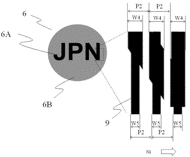
潜像要素群(5)について図4を用いて説明する。潜像要素群(5)は、第一の有意情報である、アルファベットの「A」と、第二の有意情報であるアルファベットの「B」の二つの有意情報を含む。第一の有意情報は、図4(b)に示す第一の潜像要素群(5A)によって表され、第二の有意情報は、図4(c)に示す第二の潜像要素群(5B)によって表される。第一の潜像要素群(5A)は、画線幅0.15mmの第一の潜像要素(8A)を、第一の方向(S1)にピッチ0.4mmで万線状に連続して配置し、第二の潜像要素群(5B)は、画線幅0.15mmの第二の潜像要素(8B)を第一の方向(S1)にピッチ0.4mmで万線状に連続して配置した。第一の潜像要素(8A)と第二の潜像要素(8B)は、第一の方向(S1)にピッチの半分に当たる0.2mmだけずらした構成とした。以上のような構成の潜像要素群(5)をウェットオフセット印刷によって、低光沢で透明なインキ(マットメジウム T&K TOKA製)で、蒲鉾状画線群(4)の上に形成した。 The latent image element group (5) will be described with reference to FIG. The latent image element group (5) includes two pieces of significant information, the first significant information, the alphabet “A”, and the second significant information, the alphabet “B”. The first significant information is represented by a first latent image element group (5A) shown in FIG. 4B, and the second significant information is a second latent image element group (shown in FIG. 4C). 5B). In the first latent image element group (5A), the first latent image element (8A) having an image line width of 0.15 mm is continuously formed in a single line with a pitch of 0.4 mm in the first direction (S1). In the second latent image element group (5B), the second latent image element (8B) having an image line width of 0.15 mm is continuously arranged in a single line at a pitch of 0.4 mm in the first direction (S1). Arranged. The first latent image element (8A) and the second latent image element (8B) were shifted by 0.2 mm corresponding to half the pitch in the first direction (S1). The latent image element group (5) having the above-described configuration was formed on the saddle-shaped image line group (4) by wet offset printing with a low gloss and transparent ink (made by Matte Media T & K TOKA).
図2に示す光反射要素群(6)は、アルファベットの「JPN」を表す情報部(6A)の面積率を約60%とし、その他の背景部(6B)の面積率を約30%として可視画像を構成した。具体的な構成としては、情報部(6A)は、画線幅0.25mmの光反射要素(9)を、ピッチ(P2)が0.412mmで第一の方向(S1)に万線状に配置し、背景部(6B)は、画線幅0.12mmの光反射要素(9)を、同じくピッチ(P2)が0.412mmで第一の方向(S1)に万線状に配置した。光反射要素群(6)は、ウェットオフセット印刷で銀インキ(TKSOシルバー T&K TOKA製)を用いて蒲鉾状要素群(4)と潜像要素群(5)上に印刷した。この光反射要素群(6)は、拡散反射光下では暗い灰色で正反射光下では白色となる、優れた明暗フリップフロップ性を有する。なお、光反射要素群(6)の印刷皮膜は、約1μmであった。 The light reflecting element group (6) shown in FIG. 2 is visible with the area ratio of the information part (6A) representing the alphabet “JPN” being approximately 60% and the area ratio of the other background part (6B) being approximately 30%. An image was constructed. As a specific configuration, the information section (6A) includes light reflecting elements (9) having an image line width of 0.25 mm in a line shape in the first direction (S1) with a pitch (P2) of 0.412 mm. In the background portion (6B), light reflecting elements (9) having an image line width of 0.12 mm were similarly arranged in a line shape in the first direction (S1) with a pitch (P2) of 0.412 mm. The light reflecting element group (6) was printed on the saddle-shaped element group (4) and the latent image element group (5) using silver ink (manufactured by TKSO Silver T & K TOKA) by wet offset printing. This light-reflecting element group (6) has an excellent light-dark flip-flop property that is dark gray under diffuse reflection light and white under regular reflection light. The printed film of the light reflecting element group (6) was about 1 μm.
本実施例の潜像印刷物(1)の効果について図8を用いて説明する。拡散反射光下で潜像印刷物(1)を観察した場合、可視画像(15)の「JPN」の文字が視認された。次に、図8(b)のように、左側から潜像印刷物(1)に光が入射した場合、可視画像(15)の「JPN」の文字が消失するとともに、観察者(11)には、明るい白色と金色の二つの色相の異なる色彩豊かなグラデーションを有するモアレ模様(m)の中に、第一の有意情報である「A」の文字が暗い灰色の色彩で視認された。また、図8(c)のように、右側から潜像印刷物(1)に光が入射した場合、観察者(11)には、明るい白色と金色の二つの色相の異なる色彩豊かなグラデーションを有するモアレ模様(m)の中に、第二の有意情報である「B」の文字が暗い灰色の色彩で視認された。 The effect of the latent image printed material (1) of the present embodiment will be described with reference to FIG. When the latent image print (1) was observed under diffuse reflection, the characters “JPN” in the visible image (15) were visually recognized. Next, as shown in FIG. 8B, when light is incident on the latent image printed material (1) from the left side, the characters “JPN” in the visible image (15) disappear and the viewer (11) In the moire pattern (m) having a rich gradation of two different hues of bright white and gold, the letter “A” as the first significant information was visually recognized in a dark gray color. Further, as shown in FIG. 8C, when light is incident on the latent image printed material (1) from the right side, the viewer (11) has a rich gradation in which two hues of bright white and gold are different. In the moiré pattern (m), the letter “B” as the second significant information was visually recognized in a dark gray color.
また、モアレ模様(m)は、基材(2)の傾きを僅かに変えることで、図9に示すように、第一の方向(S1)に連続的に移動する効果が確認できた。以上のように、入射する光の角度の変化に応じて、印刷画像(3)中に視認される基画像(12)がチェンジし、同時に色彩豊かなモアレ模様(m)が動いて見える効果を有することが確認できた。また、基画像(12)とモアレ模様(m)は色相が異なり、それぞれの視認性を損なうことはなかった。 Moreover, the moire pattern (m) confirmed the effect of moving continuously in the first direction (S1) as shown in FIG. 9 by slightly changing the inclination of the substrate (2). As described above, the base image (12) visually recognized in the printed image (3) changes according to the change in the angle of incident light, and at the same time, the effect that the colorful moire pattern (m) appears to move. It was confirmed that it had. Further, the hues of the base image (12) and the moire pattern (m) were different, and the visibility of each was not impaired.
1、1’ 潜像印刷物
2、2’ 基材
3、3’ 印刷画像
4、4’ 蒲鉾状要素群
5、5’ 潜像要素群
5A、5A’ 第一の潜像要素群
5B、5B’ 第二の潜像要素群
6、6’ 光反射要素群
6A、6A’ 情報部
6B、6B’ 背景部
6C’ 潜像カモフラージュ要素群
7、7’ 蒲鉾状要素
8 潜像要素
8A、8A’ 第一の潜像要素
8B、8B’第二の潜像要素
9、9’ 光反射要素
10、10’ 光源
11、11’ 観察者の視点
12 基画像
12A 第一の基画像
12B 第二の基画像
14’ 潜像カモフラージュ要素
15 可視画像
S1 第一の方向
i、m、m’ モアレ模様
f 従来技術における基画像
1, 1 'latent image printed
Claims (4)
正反射光下において前記蒲鉾状要素と異なる色彩の明暗フリップフロップ性又はカラーフリップフロップ性の少なくとも一方の光学特性を備えた光反射要素が万線状に配置された光反射要素群と、
基画像を分割及び/又は圧縮した透明又は半透明の潜像要素が万線状に配置された潜像要素群から成る印刷画像が形成され、
前記蒲鉾状要素群の上に、前記光反射要素群、前記潜像要素群の順に積層又は前記潜像要素群、前記光反射要素群の順に積層され、
前記蒲鉾状要素群及び前記光反射要素群は、要素のピッチ、配置角度、形状のいずれか一つが異なることで要素群同士の干渉によりモアレ模様が形成され、
前記基材を正反射光下で連続的に角度を変化させながら観察すると、前記潜像画像が変化及び/又は動的に視認されるとともに前記モアレ模様が動的に視認可能なことを特徴とする潜像印刷物。 A saddle-like element group in which saddle-like elements having a saddle shape formed of a resin-containing material are arranged in a line at least on a part of the substrate;
A light reflecting element group in which light reflecting elements having optical characteristics of at least one of bright and dark flip-flops or color flip-flops having a color different from that of the bowl-like elements under regular reflection light are arranged in a line;
A printed image is formed, which is composed of a group of latent image elements in which transparent or translucent latent image elements obtained by dividing and / or compressing the base image are arranged in a line,
On the bowl-shaped element group, the light reflection element group, the latent image element group are laminated in this order or the latent image element group, the light reflection element group are laminated in this order,
The saddle-like element group and the light reflecting element group are different in any one of the element pitch, the arrangement angle, and the shape so that a moire pattern is formed by interference between the element groups,
When the substrate is observed under regular reflection light while continuously changing the angle, the latent image is changed and / or dynamically visually recognized and the moire pattern is dynamically visible. Latent image printed matter.
前記光反射要素群は、面積率の差異による濃度差で可視画像を形成して成り、
前記印刷画像を拡散反射光下で観察すると前記可視画像のみが視認可能となり、正反射光下で観察すると前記モアレ模様が出現し、前記可視画像は消失して視認されないことを特徴とする請求項1記載の潜像印刷物。 At least one of the bowl-shaped element group and the light reflecting element group is formed of transparent or translucent,
The light reflecting element group is formed by forming a visible image with a density difference due to a difference in area ratio,
When the printed image is observed under diffuse reflected light, only the visible image is visible, and when observed under regular reflected light, the moire pattern appears, and the visible image disappears and is not visually recognized. The latent image printed matter according to 1.
正反射光下において前記蒲鉾状要素と異なる色彩の明暗フリップフロップ性又はカラーフリップフロップ性の少なくとも一方の光学特性を備え、かつ、拡散反射光下において前記基材と異なる色彩を有する光反射要素が万線状に配置された光反射要素群と、
拡散反射光下において前記光反射要素群と同じ色相を有し、正反射光下においては前記光反射要素と異なる色彩を有し、基画像が分割及び/又は圧縮された潜像要素が万線状に配置された潜像要素群から成る印刷画像が形成され、
前記蒲鉾状要素群の上に、
i)前記光反射要素群、前記潜像要素群の順に積層又は前記潜像要素群、前記光反射要素群の順に積層、又は、
ii)前記光反射要素群と前記潜像要素群が並置され、
前記光反射要素群は、拡散反射光下における前記印刷画像の濃度から前記潜像要素群の濃度を減じた濃度で構成され、
前記蒲鉾状要素群及び前記光反射要素群は、要素のピッチ、配置角度、形状のいずれか一つが異なることで要素群同士の干渉によりモアレ模様が形成され、
前記基材を正反射光下で連続的に角度を変化させながら観察すると、前記潜像画像が変化及び/又は動的に視認されるとともに前記モアレ模様が動的に視認可能なことを特徴とする潜像印刷物。 A cage-like element group in which transparent or translucent cage-shaped elements having a cage shape formed of a resin-containing material are arranged in a line on at least a part of the substrate;
A light-reflective element having at least one of light-dark flip-flop property or color flip-flop property of a color different from that of the bowl-like element under specular reflection light, and having a color different from that of the base material under diffuse reflection light; A group of light reflecting elements arranged in a line;
A latent image element having the same hue as that of the light reflection element group under diffuse reflection light, a color different from that of the light reflection element under regular reflection light, and a base image divided and / or compressed is a line. A printed image composed of latent image elements arranged in a shape is formed,
On the saddle-like element group,
i) Laminating in the order of the light reflecting element group and the latent image element group, or laminating in the order of the latent image element group and the light reflecting element group, or
ii) The light reflecting element group and the latent image element group are juxtaposed,
The light reflecting element group is configured with a density obtained by subtracting the density of the latent image element group from the density of the printed image under diffuse reflected light,
The saddle-like element group and the light reflecting element group are different in any one of the element pitch, the arrangement angle, and the shape so that a moire pattern is formed by interference between the element groups,
When the substrate is observed under regular reflection light while continuously changing the angle, the latent image is changed and / or dynamically visually recognized and the moire pattern is dynamically visible. Latent image printed matter.
前記光反射要素群は、面積率の差異による濃度差で可視画像を形成して成り、
前記印刷画像を拡散反射光下で観察すると前記可視画像のみが視認可能となり、正反射光下で観察すると前記モアレ模様が出現し、前記可視画像は消失して視認されないことを特徴とする請求項3記載の潜像印刷物。 At least one of the bowl-shaped element group and the light reflecting element group is formed of transparent or translucent,
The light reflecting element group is formed by forming a visible image with a density difference due to a difference in area ratio,
When the printed image is observed under diffuse reflected light, only the visible image is visible, and when observed under regular reflected light, the moire pattern appears, and the visible image disappears and is not visually recognized. 3. The latent image printed matter according to 3.
Priority Applications (1)
| Application Number | Priority Date | Filing Date | Title |
|---|---|---|---|
| JP2016155243A JP2018024104A (en) | 2016-08-08 | 2016-08-08 | Latent image printed matter |
Applications Claiming Priority (1)
| Application Number | Priority Date | Filing Date | Title |
|---|---|---|---|
| JP2016155243A JP2018024104A (en) | 2016-08-08 | 2016-08-08 | Latent image printed matter |
Publications (1)
| Publication Number | Publication Date |
|---|---|
| JP2018024104A true JP2018024104A (en) | 2018-02-15 |
Family
ID=61194412
Family Applications (1)
| Application Number | Title | Priority Date | Filing Date |
|---|---|---|---|
| JP2016155243A Pending JP2018024104A (en) | 2016-08-08 | 2016-08-08 | Latent image printed matter |
Country Status (1)
| Country | Link |
|---|---|
| JP (1) | JP2018024104A (en) |
Cited By (3)
| Publication number | Priority date | Publication date | Assignee | Title |
|---|---|---|---|---|
| JP2019202438A (en) * | 2018-05-22 | 2019-11-28 | 独立行政法人 国立印刷局 | Forgery preventive printed matter |
| JP2020138383A (en) * | 2019-02-27 | 2020-09-03 | 独立行政法人 国立印刷局 | Latent image printed matter |
| JP2022088817A (en) * | 2020-12-03 | 2022-06-15 | 独立行政法人 国立印刷局 | Functional image line printed matter |
Citations (7)
| Publication number | Priority date | Publication date | Assignee | Title |
|---|---|---|---|---|
| US20050040643A1 (en) * | 2003-08-20 | 2005-02-24 | Mancuso Robert J. | Variable color print of an image |
| JP2011126028A (en) * | 2009-12-15 | 2011-06-30 | National Printing Bureau | Latent image printed matter |
| JP2013240918A (en) * | 2012-05-21 | 2013-12-05 | National Printing Bureau | Latent image printed matter |
| JP2014180796A (en) * | 2013-03-19 | 2014-09-29 | National Printing Bureau | Moving image/pattern-printed matter |
| JP2014201048A (en) * | 2013-04-10 | 2014-10-27 | 独立行政法人 国立印刷局 | Print having dynamic effect |
| JP2016221888A (en) * | 2015-06-02 | 2016-12-28 | 独立行政法人 国立印刷局 | Latent image printed matter |
| JP2017056576A (en) * | 2015-09-15 | 2017-03-23 | 独立行政法人 国立印刷局 | Latent image printed matter |
-
2016
- 2016-08-08 JP JP2016155243A patent/JP2018024104A/en active Pending
Patent Citations (7)
| Publication number | Priority date | Publication date | Assignee | Title |
|---|---|---|---|---|
| US20050040643A1 (en) * | 2003-08-20 | 2005-02-24 | Mancuso Robert J. | Variable color print of an image |
| JP2011126028A (en) * | 2009-12-15 | 2011-06-30 | National Printing Bureau | Latent image printed matter |
| JP2013240918A (en) * | 2012-05-21 | 2013-12-05 | National Printing Bureau | Latent image printed matter |
| JP2014180796A (en) * | 2013-03-19 | 2014-09-29 | National Printing Bureau | Moving image/pattern-printed matter |
| JP2014201048A (en) * | 2013-04-10 | 2014-10-27 | 独立行政法人 国立印刷局 | Print having dynamic effect |
| JP2016221888A (en) * | 2015-06-02 | 2016-12-28 | 独立行政法人 国立印刷局 | Latent image printed matter |
| JP2017056576A (en) * | 2015-09-15 | 2017-03-23 | 独立行政法人 国立印刷局 | Latent image printed matter |
Cited By (5)
| Publication number | Priority date | Publication date | Assignee | Title |
|---|---|---|---|---|
| JP2019202438A (en) * | 2018-05-22 | 2019-11-28 | 独立行政法人 国立印刷局 | Forgery preventive printed matter |
| JP2020138383A (en) * | 2019-02-27 | 2020-09-03 | 独立行政法人 国立印刷局 | Latent image printed matter |
| JP7089250B2 (en) | 2019-02-27 | 2022-06-22 | 独立行政法人 国立印刷局 | Latent image printed matter |
| JP2022088817A (en) * | 2020-12-03 | 2022-06-15 | 独立行政法人 国立印刷局 | Functional image line printed matter |
| JP7536253B2 (en) | 2020-12-03 | 2024-08-20 | 独立行政法人 国立印刷局 | Functional line prints |
Similar Documents
| Publication | Publication Date | Title |
|---|---|---|
| JP5200284B2 (en) | Latent image printed matter | |
| JP2018024105A (en) | Latent image printed matter | |
| JP6399359B2 (en) | Latent image printed matter | |
| JP6381041B2 (en) | Stacked visual effect structure | |
| JP2016203459A (en) | Latent image printed matter | |
| JP2018024104A (en) | Latent image printed matter | |
| JP6300101B2 (en) | Special latent image | |
| JP6032429B2 (en) | Movie print | |
| JP2017144558A (en) | Latent image printed matter | |
| JP6097997B2 (en) | Latent image printed matter | |
| JP6032419B2 (en) | Latent image printed matter | |
| JP6394984B2 (en) | Latent image printed matter | |
| JP7185876B2 (en) | latent image print | |
| JP6032426B2 (en) | Latent image printed matter | |
| JP6557828B2 (en) | Latent image printed matter | |
| JP6032430B2 (en) | Movie print | |
| JP4977895B2 (en) | Stereoscopic image forming body | |
| JP5721105B2 (en) | Latent image printed matter | |
| JP2020037215A (en) | Latent image printed matter | |
| JP2014000762A (en) | Latent image printed matter | |
| JP6886662B2 (en) | Latent image printed matter | |
| JP7541680B2 (en) | Latent image print | |
| JP6516262B2 (en) | Latent image printed matter | |
| JP2017056641A (en) | Information carrier that can detect authenticity | |
| JP6418576B2 (en) | Latent image printed matter, latent image line group producing method of latent image printed matter, and latent image line group producing software for latent image printed matter |
Legal Events
| Date | Code | Title | Description |
|---|---|---|---|
| A621 | Written request for application examination |
Free format text: JAPANESE INTERMEDIATE CODE: A621 Effective date: 20180907 |
|
| A977 | Report on retrieval |
Free format text: JAPANESE INTERMEDIATE CODE: A971007 Effective date: 20190621 |
|
| A131 | Notification of reasons for refusal |
Free format text: JAPANESE INTERMEDIATE CODE: A131 Effective date: 20190703 |
|
| A02 | Decision of refusal |
Free format text: JAPANESE INTERMEDIATE CODE: A02 Effective date: 20191223 |