JP2018024151A - Image forming apparatus, control method thereof, and program - Google Patents
Image forming apparatus, control method thereof, and program Download PDFInfo
- Publication number
- JP2018024151A JP2018024151A JP2016156859A JP2016156859A JP2018024151A JP 2018024151 A JP2018024151 A JP 2018024151A JP 2016156859 A JP2016156859 A JP 2016156859A JP 2016156859 A JP2016156859 A JP 2016156859A JP 2018024151 A JP2018024151 A JP 2018024151A
- Authority
- JP
- Japan
- Prior art keywords
- screen
- operation screen
- control unit
- forming apparatus
- image forming
- Prior art date
- Legal status (The legal status is an assumption and is not a legal conclusion. Google has not performed a legal analysis and makes no representation as to the accuracy of the status listed.)
- Granted
Links
Images


Classifications
-
- H—ELECTRICITY
- H04—ELECTRIC COMMUNICATION TECHNIQUE
- H04N—PICTORIAL COMMUNICATION, e.g. TELEVISION
- H04N1/00—Scanning, transmission or reproduction of documents or the like, e.g. facsimile transmission; Details thereof
- H04N1/0035—User-machine interface; Control console
- H04N1/00501—Tailoring a user interface [UI] to specific requirements
- H04N1/00503—Customising to a particular machine or model, machine function or application
-
- H—ELECTRICITY
- H04—ELECTRIC COMMUNICATION TECHNIQUE
- H04N—PICTORIAL COMMUNICATION, e.g. TELEVISION
- H04N1/00—Scanning, transmission or reproduction of documents or the like, e.g. facsimile transmission; Details thereof
- H04N1/0035—User-machine interface; Control console
- H04N1/00405—Output means
- H04N1/00408—Display of information to the user, e.g. menus
- H04N1/00411—Display of information to the user, e.g. menus the display also being used for user input, e.g. touch screen
-
- H—ELECTRICITY
- H04—ELECTRIC COMMUNICATION TECHNIQUE
- H04N—PICTORIAL COMMUNICATION, e.g. TELEVISION
- H04N1/00—Scanning, transmission or reproduction of documents or the like, e.g. facsimile transmission; Details thereof
- H04N1/0035—User-machine interface; Control console
- H04N1/00501—Tailoring a user interface [UI] to specific requirements
- H04N1/00506—Customising to the data to be displayed
-
- H—ELECTRICITY
- H04—ELECTRIC COMMUNICATION TECHNIQUE
- H04N—PICTORIAL COMMUNICATION, e.g. TELEVISION
- H04N1/00—Scanning, transmission or reproduction of documents or the like, e.g. facsimile transmission; Details thereof
- H04N1/00912—Arrangements for controlling a still picture apparatus or components thereof not otherwise provided for
- H04N1/00938—Software related arrangements, e.g. loading applications
- H04N1/00941—Interaction of different applications
-
- H—ELECTRICITY
- H04—ELECTRIC COMMUNICATION TECHNIQUE
- H04N—PICTORIAL COMMUNICATION, e.g. TELEVISION
- H04N1/00—Scanning, transmission or reproduction of documents or the like, e.g. facsimile transmission; Details thereof
- H04N1/00912—Arrangements for controlling a still picture apparatus or components thereof not otherwise provided for
- H04N1/00952—Using a plurality of control devices, e.g. for different functions
-
- H—ELECTRICITY
- H04—ELECTRIC COMMUNICATION TECHNIQUE
- H04N—PICTORIAL COMMUNICATION, e.g. TELEVISION
- H04N2201/00—Indexing scheme relating to scanning, transmission or reproduction of documents or the like, and to details thereof
- H04N2201/0077—Types of the still picture apparatus
- H04N2201/0094—Multifunctional device, i.e. a device capable of all of reading, reproducing, copying, facsimile transception, file transception
Landscapes
- Engineering & Computer Science (AREA)
- Multimedia (AREA)
- Signal Processing (AREA)
- Human Computer Interaction (AREA)
- Facsimiles In General (AREA)
- Accessory Devices And Overall Control Thereof (AREA)
- Stored Programmes (AREA)
Abstract
【課題】画像形成装置の限られたリソースの消費を抑えつつ、ネイティブプログラムを操作するUIと、拡張機能を操作するUIを好適に共存させることにより、ユーザの利便性を確保する仕組みを提供する。【解決手段】本画像形成装置は、標準機能の操作画面を描画する標準機能用画面バッファ制御部と、拡張機能の操作画面を描画するアプリケーション用画面バッファ制御部とを備える。さらに、本画像形成装置は、標準機能用画面バッファ制御部又はアプリケーション用画面バッファ制御部によって描画された操作画面を出力する。当該出力において、アプリケーション用画面バッファ制御部によって描画された操作画面、即ち、拡張機能の操作画面を出力する場合には、標準機能の操作画面の一部を、拡張機能の操作画面に組み込んで出力する。【選択図】 図8Provided is a mechanism for ensuring user convenience by suitably coexisting a UI for operating a native program and a UI for operating an extended function while suppressing consumption of limited resources of an image forming apparatus. . The image forming apparatus includes a standard function screen buffer control unit for rendering a standard function operation screen, and an application screen buffer control unit for rendering an extended function operation screen. Further, the image forming apparatus outputs an operation screen drawn by the standard function screen buffer control unit or the application screen buffer control unit. When outputting the operation screen drawn by the application screen buffer control unit, that is, the extended function operation screen, a part of the standard function operation screen is incorporated into the extended function operation screen and output. To do. [Selection] Figure 8
Description
本発明は、画像形成装置、その制御方法、及びプログラムに関する。 The present invention relates to an image forming apparatus, a control method thereof, and a program.
画像形成装置に拡張アプリケーションをインストールし、画像形成装置の機能を拡張できるシステムが普及している。これらのシステムには、画像形成装置の制御アプリケーションとは別に、拡張プログラムをアドインして拡張アプリケーションを動作させる実行環境を有する。特許文献1には、可搬記憶媒体を利用した、拡張プログラムの設定情報のエクスポート、及びインポートを実現する技術について提案されている。
A system in which an extension application is installed in an image forming apparatus and the functions of the image forming apparatus can be expanded has become widespread. In addition to the control application of the image forming apparatus, these systems have an execution environment in which an extension program is added in to operate the extension application.
しかしながら、上記従来技術には以下に記載する課題がある。例えば、画像形成装置のコピー等の標準機能を操作するUIと、拡張機能を操作するUIを共存させるためにWINDOWマネージャを搭載する方法が知られている。このようなWINDOWマネージャを実現するには高速なCPUやGPU、メモリ等の多くのハードウェアリソースを消費する必要がある。しかし、リソースの限られた画像形成装置では、標準機能を操作するUIと、拡張機能を操作するUIを共存させることが難しく、ユーザの利便性が損なわれていた。 However, the above prior art has the following problems. For example, a method is known in which a WINDOW manager is installed so that a UI that operates standard functions such as copying of an image forming apparatus and a UI that operates extended functions coexist. In order to realize such a WINDOW manager, it is necessary to consume many hardware resources such as a high-speed CPU, GPU, and memory. However, in an image forming apparatus with limited resources, it is difficult for a UI that operates standard functions and a UI that operates extended functions to coexist, and user convenience is impaired.
本発明は、上述の問題に鑑みて成されたものであり、画像形成装置の限られたリソースの消費を抑えつつ、標準機能を操作するUIと、拡張機能を操作するUIを好適に共存させることにより、ユーザの利便性を確保する仕組みを提供することを目的とする。 The present invention has been made in view of the above-described problems. A UI for operating a standard function and a UI for operating an extended function preferably coexist while suppressing consumption of limited resources of the image forming apparatus. Accordingly, an object is to provide a mechanism for ensuring user convenience.
本発明は、画像形成装置であって、前記画像形成装置のネイティブプログラムを制御する第1制御手段と、前記ネイティブプログラムとは異なる拡張アプリケーションを制御する第2制御手段と、前記第1制御手段によって制御されるネイティブプログラムの操作画面を描画する第1バッファ制御手段と、前記第2制御手段によって制御される拡張アプリケーションの操作画面を描画する第2バッファ制御手段と、前記第1バッファ制御手段又は前記第2バッファ制御手段によって描画された操作画面を出力する出力処理手段とを備え、前記出力処理手段は、前記第2バッファ制御手段によって描画された操作画面を出力する場合には、前記ネイティブプログラムの操作画面の一部を、前記拡張アプリケーションの操作画面に組み込んで出力することを特徴とする。 The present invention is an image forming apparatus, comprising: a first control unit that controls a native program of the image forming apparatus; a second control unit that controls an extended application different from the native program; and the first control unit. A first buffer control means for drawing an operation screen of a controlled native program; a second buffer control means for drawing an operation screen of an extended application controlled by the second control means; the first buffer control means; Output processing means for outputting the operation screen drawn by the second buffer control means, and the output processing means outputs the operation screen drawn by the second buffer control means when the native program Part of the operation screen is incorporated into the operation screen of the extended application and output And wherein the Rukoto.
本発明によれば、画像形成装置の限られたリソースの消費を抑えつつ、標準機能を操作するUIと、拡張機能を操作するUIを好適に共存させることにより、ユーザの利便性を確保することができる。 According to the present invention, it is possible to ensure user convenience by suitably coexisting a UI that operates a standard function and a UI that operates an extended function while suppressing consumption of limited resources of the image forming apparatus. Can do.
以下、添付図面を参照して本発明の実施形態を詳しく説明する。なお、以下の実施形態は特許請求の範囲に係る本発明を限定するものでなく、また本実施形態で説明されている特徴の組み合わせの全てが本発明の解決手段に必須のものとは限らない。 Hereinafter, embodiments of the present invention will be described in detail with reference to the accompanying drawings. The following embodiments do not limit the present invention according to the claims, and all combinations of features described in the present embodiments are not necessarily essential to the solution means of the present invention. .
<第1の実施形態>
<画像形成装置の構成>
以下では、本発明の第1の実施形態について説明する。まず、図1を参照して、画像形成装置の主要部の構成の一例について説明する。
<First Embodiment>
<Configuration of image forming apparatus>
Hereinafter, a first embodiment of the present invention will be described. First, an example of a configuration of a main part of the image forming apparatus will be described with reference to FIG.
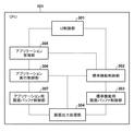
画像形成装置10は、コントローラユニット100、操作部112、スキャナ170、及びプリンタ195を備える。さらに、画像形成装置10には、USBストレージ114が着脱可能である。コントローラユニット100は、CPU101、RAM102、ROM103、ストレージ104、画像パスI/F105、操作部I/F106、ネットワークI/F110、及びUSBホストI/F113を備える。これらのコンポーネントは、システムバス107を介して接続される。さらに、コントローラユニット100は、デバイスI/F120、スキャナ画像処理部180、及びプリンタ画像処理部190を備える。これらのコンポーネントは画像バス108を介して接続される。なお、画像パスI/F105は、システムバス107及び画像バス108の両方に接続される。
The
コントローラユニット100は、スキャナ170で読み取られた画像データをプリンタ195により印刷出力するコピー機能を実現するための制御を行う。CPU101は、ROM103に格納されているブートアプリケーションによりオペレーションシステム(OS)を立ち上げる。CPU101は、このOS上で、ストレージ104に格納されているアプリケーションを実行し、これによって各種処理を実行する。このCPU101の作業領域としてはRAM102が用いられる。RAM102は、作業領域を提供するとともに、画像データを一時記憶するための画像メモリ領域を提供する。ストレージ104は、アプリケーションや画像データを格納する。
The
操作部I/F106は、タッチパネルを有する操作部112とのインタフェースであり、操作部112に表示すべき画像データを操作部112に対して出力する。また、操作部I/F106は、操作部112においてユーザにより入力された情報をCPU101に送出する。ネットワークI/F110は、画像形成装置10をLANに接続するためのインタフェースである。
The operation unit I /
USBホストI/F113は、USBストレージ114と通信するインタフェース部である。USBホストI/F113は、ストレージ104に格納されているデータをUSBストレージ114に記憶させるための出力部である。また、USBホストI/F113は、USBストレージ114に格納されているデータを入力し、CPU101にそれを伝える。USBストレージ114は、データを格納する外部記憶装置であり、USBホストI/F113に対して着脱可能である。USBホストI/F113には、USBストレージ114を含む複数のUSBデバイスが接続可能である。
The USB host I / F 113 is an interface unit that communicates with the
画像バスI/F105は、システムバス107と、画像データを高速で転送する画像バス108とを接続し、データ形式を変換するためのバスブリッジである。画像バス108は、PCIバス又はIEEE1394等によって構成される。デバイスI/F120には、スキャナ170及びプリンタ195が接続され、デバイスI/F120は、画像データの同期系/非同期系の変換を行う。スキャナ画像処理部180は、入力画像データに対し補正、加工、編集を行う。プリンタ画像処理部190は、プリント出力画像データに対してプリンタ195に応じた補正、解像度変換などを行う。
The image bus I / F 105 is a bus bridge for connecting the
<拡張アプリケーション>
次に、図2を参照して、画像形成装置10の拡張アプリケーションの実行環境の一例について説明する。ここで、拡張アプリケーションとは、標準機能以外の拡張機能を提供するためのアプリケーションである。ストレージ104に記憶されているアプリケーションを、CPU101がRAM102にロードし、アプリケーションを実行することで図2の各モジュールが実現される。
<Extended application>
Next, an example of the execution environment of the extended application of the
オペレーティングシステムであるOS201上には、プリンタやFAX、スキャナなどの画像処理ユニットを制御するためのネイティブプログラム210と、拡張アプリケーションの実行環境である仮想マシン(Virtual Machine:VM)230が動作している。VM230は、拡張アプリケーションを制御するアプリケーションを理解し実行するモジュールである。拡張アプリケーションは、必ずVM230上で動作する。本実施形態に係るVM230は、CPU101上で動作するソフトウェアモジュールであるが、ハードウェアモジュールであってもよい。VMは、インタープリタであり、Java(登録商標)であってもよい。また、VMは、バイトコードを解釈するインタプリタであれば、例えば、スクリプト言語であるLua言語の解釈系でもよい。
On the
ネイティブプログラム210には、プリンタやFAX、スキャナなどの画像処理ユニットを制御するためのネイティブスレッド214と、仮想マシン230を動かすためのVMスレッド215とが含まれる。VMスレッドはVM230の数に対応する数存在する。ここでは、211、212,213の3つのスレッドが生成されている。ネイティブプログラム210は、画像形成装置のネイティブの機能を直接的に制御するファームウェア(リアルタイムOS)の一部、または、当該ファームウェアが呼び出すライブラリとして構成されてもよい。そのライブラリは、C言語など、画像形成装置のネイティブの機能を直接的に制御する制御プログラム群として構成されてもよい。
The
VMシステムサービス220は、拡張アプリケーションから共通利用されるユーティリティライブラリである。拡張アプリケーション240からVMシステムサービス220の機能を呼び出すことにより、拡張アプリケーションを開発する手間を省く、又は画像形成装置10の各モジュールへアクセスすることができる。VMシステムサービス220には、VMとして最低限動作させる標準VMシステムサービス221と、画像形成装置10の各モジュールにアクセスや、OSの機能を提供する拡張VMシステムサービス222が含まれる。
The
VM230は、拡張アプリケーション240を実行する。VM230は、拡張アプリケーションのスレッド毎に生成される。図2の例では拡張アプリケーションA241で2つのスレッドを動かすためのVM A−1 231 と、VM A−2 232、拡張アプリケーションB242で1つのスレッドを動かすためのVM B−1 233が生成されている。
The
また、画像形成装置10の操作部112に表示されるメインメニュー画面には、拡張アプリケーションごとのアイコンが表示される。このアイコンをユーザが選択したことを、操作部112を通じて操作部I/F106が検知すると、操作部I/F106はその旨をCPU101に送信する。その旨を受け取ったCPU101はユーザによって選択された拡張アプリケーションを起動する。
In addition, an icon for each extended application is displayed on the main menu screen displayed on the
<ソフトウェアモジュール>
次に、図3を参照して、本実施形態に係る画像形成装置10のCPU101上で動作するソフトウェアモジュールの構成例について説明する。
<Software module>
Next, a configuration example of a software module that operates on the
画像形成装置10は、ソフトウェアモジュールとして、UI制御部301、標準機能制御部302、標準機能用画面バッファ制御部303、及び画面出力処理部304を備える。さらに、画像形成装置10は、アプリケーション管理部305、アプリケーション実行制御部306、及びアプリケーション用画面バッファ制御部307を備える。UI制御部301は、操作部112を通してユーザが操作した情報を検出し、状況に応じて検出した操作情報を標準機能制御部302、又はアプリケーション管理部305に通知を切り替えて通知するモジュールである。
The
標準機能制御部302は、第1制御手段として機能し、UI制御部301から通知された操作情報に基づき、コピー、スキャン、FAX等、画像形成装置10の標準機能(ネイティブプログラム)を制御する。また、ユーザにとって操作に必要な情報を、標準機能用画面バッファ制御部303を通して描画し、画面出力処理部304を通して操作部112に表示するモジュールである。さらに、図4に示す画像形成装置10の機能を呼び出すホーム画面400を制御し、アプリケーション(拡張アプリケーション)を実行するアイコンが選択された場合に、アプリケーション起動要求をアプリケーション管理部305に通知する。ここで、拡張アプリケーションとは、ネイティブプログラムとは異なり、画像形成装置10の標準機能以外の機能を提供するためにインストールされたアプリケーションを示す。当該拡張アプリケーションについては、画像形成装置の製品出荷時に既にインストールされていてもよいし、製品出荷後にインストールされてもよい。
The standard
標準機能用画面バッファ制御部303は、第1バッファ制御手段として機能し、標準機能制御部302が描画する画面バッファを制御するモジュールである。このバッファに描画された画像が画面出力処理部304を通して操作部112に表示される。画面出力部304は、状況に応じて操作部112に表示するバッファを、標準機能用画面バッファ制御部303、又は、アプリケーション用画面バッファ制御部307に切り替えて表示を行うモジュールである。
The standard function screen
アプリケーション管理部305は、第2制御手段として機能し、標準機能制御部302から通知されたアプリケーション起動要求を受けた際の指定アプリケーションの起動処理と、UI制御部301から通知された操作情報をアプリケーション実行制御部306に通知を行うモジュールである。アプリケーション実行制御部306は、アプリケーション管理部305から指定されたアプリケーションを実行するモジュールである。さらにしアプリケーション実行制御部306は、アプリケーション操作画面を、アプリケーション用画面バッファ制御部307を通して描画し、画面出力処理部304を通して操作部112に表示する。アプリケーション用画面バッファ制御部307は、第2バッファ制御手段として機能し、アプリケーション実行制御部306が描画する画面バッファを制御するモジュールである。
The
<ホーム画面>
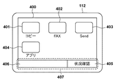
次に、図4を参照して、本実施形態に係る画像形成装置10の操作部112に表示するホーム画面400の一例について説明する。ホーム画面400は、標準機能制御部302が標準機能用画面バッファ制御部303を通して描画した画面を、画面出力処理部304が操作部112に出力した画面である。
<Home screen>
Next, an example of the
ホーム画面400は、ユーザが画像形成装置10の機能を呼び出すために利用する画面であり、この画面に表示されたコピー、FAX、Sendのような画像形成装置10の標準機能や、アプリを起動するためのアイコンを含んで表示される。これらのアイコンをユーザが選択することで、選択したアイコンが示す機能が動作する。コピーアイコン401、FAXアイコン402、及びSendアイコン403は、選択するとそれぞれコピー機能、FAX機能、Send機能の設定画面を表示する。アプリアイコン404を選択すると、当該アイコンに紐付けられたアプリを起動する。
The
また、ホーム画面400の下部には、状況確認ボタン405が選択可能に表示されるとともに、ステータス表示領域406が設けられる。状況確認ボタン405を選択すると、図7に示す画像形成装置10の状況を確認するための状況確認画面700が表示される。ステータス表示領域406は、画像形成装置10の状態を表示する領域である。状況確認ボタン405を選択すると、画像形成装置10の状況を確認するための状況確認画面700を表示する。ここでは、状況確認ボタン405とステータス表示領域406を合わせた表示領域をフッター領域407と称し、本実施形態における画像形成装置10の様々な画面に共通して表示される領域である。つまり、標準機能の画面と、その他のアプリケーションの画面との両方で共通して表示される領域となる。このような領域を設けることで、ユーザが標準機能であるネイティブプログラムか、又は、他の拡張したアプリケーションかを意識することなく操作を行うことができ、UIの利便性を向上することができる。
A
<標準機能選択シーケンス>
次に、図5を参照して、ユーザが図4で示すホーム画面400のコピーアイコン(標準機能)401を選択した際に、図6で示すコピー設定画面600を表示するまでの処理のシーケンスについて説明する。以下で説明する処理は、例えば、CPU101がROM103やストレージ104に格納されたプログラムをRAM102に読み出して実行することによって実現される。
<Standard function selection sequence>
Next, referring to FIG. 5, when the user selects the copy icon (standard function) 401 on the
まず、S5001で、UI制御部301は、ユーザの操作を検出する。続いて、S5002で、UI制御部301は、操作情報を標準機能制御部302及びアプリケーション管理部305のいずれに通知するかを決定する操作情報通知処理を実行する。ここでは、標準機能制御部302に決定されたと想定する。さらに、S5003で、UI制御部301は、S5002の操作情報通知処理で決定された通知先である標準機能制御部302に操作情報を通知する。
First, in step S5001, the
次に、S5004で、標準機能制御部302は、現在表示している画面と、受信した操作情報とに基づき、どのような操作が行われたかを識別する操作識別処理を実行する。ここではコピーアイコン401が選択されたことが識別される。続いて、S5005で、標準機能制御部302は、図6のコピー設定画面600を描画するために標準機能用画面バッファ制御部303に対し描画要求を行う。標準機能用画面バッファ制御部303は、描画要求を受け画面を描画する。
In step S <b> 5004, the standard
次に、S5006で、標準機能制御部302は、描画した画面を表示するため、画面出力要求を送信する画面出力要求送信処理を実行する。S5007で、標準機能制御部302は、画面出力処理部304に出力要求を行う。S5008で、画面出力処理部304は、出力要求を受けて画面出力処理を実行し、当該画面を操作部112に出力する。
Next, in step S5006, the standard
<コピー設定画面>
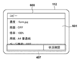
次に、図6を参照して、図4のコピーアイコン401を選択した際に操作部112に表示されるコピー設定画面600について説明する。ユーザは、コピー設定画面600を操作して画像形成装置10のコピー機能を利用することができる。601は、コピーの設定を表示、編集するためのコピー設定領域である。図6に示すように、コピー設定画面600においても、図4に示すホーム画面400と同様にフッター領域407が表示される。
<Copy setting screen>
Next, a
<状況確認画面>
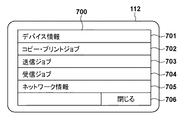
次に、図7を参照して、状況確認ボタン405を選択した際に操作部112に表示される、画像形成装置10の状況確認画面700について説明する。状況確認画面700には、画像形成装置10の各種状況を確認するためのボタン701乃至705が表示され、それらを選択することで各種状況を確認するための画面が操作部112に表示される。
<Status confirmation screen>
Next, a
デバイス情報ボタン701は、画像形成装置10のシリアル番号やファームウェアのバージョンを確認する画面を表示するためのボタンである。コピー・プリントジョブボタン702は、画像形成装置10が処理したコピー・プリントジョブの処理状況、履歴を表示するためのボタンである。送信ジョブボタン703は、画像形成装置10が処理した送信ジョブの処理状況、履歴を表示するためのボタンである。受信ジョブボタン704は、画像形成装置10が処理した受信ジョブの処理状況、履歴を表示するためのボタンである。ネットワーク情報ボタン705は、画像形成装置10のネットワークIPアドレスや、ネットワーク設定を表示するボタンである。閉じるボタン706は、この状況確認画面700を閉じて元の画面に戻るボタンである。
A
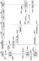
<拡張アプリ選択シーケンス>
次に、図8を参照して、図4のアプリアイコン404を選択してアプリケーション(拡張アプリ)を起動し、図11のアプリケーションの拡張アプリ画面1100を表示するシーケンスについて説明する。以下で説明する処理は、例えば、CPU101がROM103やストレージ104に格納されたプログラムをRAM102に読み出して実行することによって実現される。
<Extended application selection sequence>
Next, a sequence for starting the application (extended application) by selecting the
まず、S8002で、UI制御部301は、ユーザの操作を検出する。続いて、S8002で、UI制御部301は、操作情報を標準機能制御部302及びアプリケーション管理部305のいずれに通知するかを決定する操作情報通知処理を実行する。ここでは、標準機能制御部302に決定されたと想定する。さらに、S8003で、UI制御部301は、S8002の操作情報通知処理で決定された通知先である標準機能制御部302に操作情報を通知する。
First, in step S8002, the
次に、S8004で、標準機能制御部302は、現在表示している画面と、受信した操作情報とに基づき、どのような操作が行われたかを識別する操作識別処理を実行する。ここではアプリアイコン404が選択されたことが識別される。続いて、S8005で、標準機能制御部302は、アプリケーションのアイコンが選択されたことを通知するアプリケーションアイコン押下通知をアプリケーション管理部305に送信する。
In step S <b> 8004, the standard
次に、S8006で、アプリケーション管理部305は、押下されたアイコンに対応するアプリケーションを起動するため、アプリケーション実行制御部306にアプリケーション起動要求を行う。続いて、S8007で、アプリケーション実行制御部306は、アプリケーション起動要求を受け、アプリケーションの画面を表示するため画面出力処理部304に対し切替要求を通知し、S8008でUI制御部301に対し操作情報通知要求を通知する。UI制御部301は、操作情報通知要求を受け、S8013で、通知先切替処理を実行し、通知先をアプリケーション管理部に切り替える。
In step S8006, the
一方、画面出力処理部304は、S8009で、切替要求を受け画面の出力元をアプリケーション用画面バッファ制御部307に切り替える画面出力元切替処理を実行する。その後、S8010で、アプリケーション実行制御部306は、アプリケーションの操作画面を描画するためアプリケーション用画面バッファ制御部307に対し、描画要求を行う。さらに、S8011で、アプリケーション実行制御部306は、描画した操作画面を表示するために画面出力処理部304に対し出力要求を通知する。出力要求を受けた画面出力処理部304は、S8012で、画面出力処理を事項する。
On the other hand, in step S8009, the screen
次に、S8014で、UI制御部301は、ユーザの操作を検出する。続いて、S8015で、UI制御部301は、操作情報を標準機能制御部302及びアプリケーション管理部305のいずれに通知するか決定する操作情報通知処理を実行する。ここでは、S8013の通知先切替処理によって通知先がアプリケーション管理部305に変更されているため、UI制御部301は、S8016で、操作情報をアプリケーション管理部305に通知する。その後、S8017で、アプリケーション管理部305は、受信した操作情報を、アプリケーションを実行しているアプリケーション実行制御部306に通知する。この処理でアプリケーションが起動され、アプリケーションの操作画面の表示、操作情報のアプリケーション実行制御部306への通知が行われる。
In step S <b> 8014, the
<操作情報通知処理>
次に、図9を参照して、図5、図8、及び図14の操作情報通知処理(S5001、S8002、S8015、S1402、S1413)の詳細な処理手順について説明する。以下で説明する処理は、例えば、CPU101がROM103やストレージ104に格納されたプログラムをRAM102に読み出して実行することによって実現される。
<Operation information notification process>
Next, a detailed processing procedure of the operation information notification processing (S5001, S8002, S8015, S1402, and S1413) of FIGS. 5, 8, and 14 will be described with reference to FIG. The processing described below is realized, for example, when the
まず、S900で、UI制御部301は、アプリケーションからの操作情報通知要求が有効かどうかを判定する。操作情報通知要求が有効な場合はS901に進み、無効な場合はS902に進む。S901で、UI制御部301は、現在の操作情報通知対象がアプリケーション管理部305であるか、又は、標準機能制御部302であるかを判定する。UI制御部301の操作情報通知対象がアプリケーションだった場合はS903に進み、操作対象が標準機能だった場合はS902に進む。
First, in step S900, the
S903で、UI制御部301は、操作対象領域がフッター領域407であるか否かを判定する。フッター領域407であればS902に進み、フッター領域407でなければS904に進む。S904で、UI制御部301は、アプリケーション管理部305に操作情報を通知し、処理を終了する。一方、S902で、UI制御部301は、標準機能制御部302に操作情報を通知し、処理を終了する。
In step S <b> 903, the
<画面出力処理>
次に、図10を参照して、図5、図8、図12、及び図14の画面出力処理(S5008、S8012、S1204、S1409、S1420)の詳細な処理手順について説明する。以下で説明する処理は、例えば、CPU101がROM103やストレージ104に格納されたプログラムをRAM102に読み出して実行することによって実現される。
<Screen output processing>
Next, a detailed processing procedure of the screen output processing (S5008, S8012, S1204, S1409, S1420) of FIGS. 5, 8, 12, and 14 will be described with reference to FIG. The processing described below is realized, for example, when the
まず、S1001で、画面出力処理部304は、現在の出力元がアプリケーション用画面バッファであるか、又は、標準機能制用画面バッファであるかを判定する。ここで出力元がアプリケーション用バッファの場合はS1003に進み、標準機能用画面バッファの場合はS1002に進む。S1002で、画面出力処理部304は、標準機能用画面バッファの内容を出力し処理を終了する。
In step S1001, the screen
一方、S1003で、画面出力処理部304は、標準機能用画面バッファからフッター領域407をアプリケーション用画面バッファにコピーしS1004に進む。S1004で、画面出力処理部304は、アプリケーション用画面バッファの内容を出力し処理を終了する。この処理によって、アプリケーションが表示する画面のフッター領域407に、標準機能と同じものを表示することができる。
On the other hand, in step S1003, the screen
<拡張アプリ画面>
次に、図11を参照して、アプリケーション(拡張アプリケーション)が表示する画面例について説明する。この拡張アプリ画面1100は、アプリケーション実行制御部306で動作するアプリケーションがアプリケーション用画面バッファ制御部307を通して描画した画面を、画面出力処理部304が操作部112に出力した画面である。この例では予め登録している画像フォームの印刷を行うアプリケーションの実行画面で説明する。
<Extended application screen>
Next, an example of a screen displayed by the application (extended application) will be described with reference to FIG. The
1101は、予め登録したフォームの印刷設定を表示する領域である。1102は、このフォームの印刷を実行することを決定するボタンである。1103は、このフォームの印刷をキャンセルすることを決定するボタンである。フッター領域407は、画面出力処理部304によって、標準機能制御部302が描画したフッター部をコピーして表示している領域である。この画面を表示している間のユーザの操作情報は、基本的に、操作情報通知処理(S5002)によってアプリケーション管理部305に通知される。その後、アプリケーション管理部305からアプリケーション実行制御部306内で実行されるアプリケーション(拡張アプリケーション)に通知される。一方で、詳細については後述するが、フッター領域407への操作については、標準機能制御部302へ通知される。
<画面出力制御シーケンス>
次に、図12を参照して、図11の拡張アプリ画面1100を表示中のフッター領域407への画面出力制御のシーケンスについて説明する。以下で説明する処理は、例えば、CPU101がROM103やストレージ104に格納されたプログラムをRAM102に読み出して実行することによって実現される。
<Screen output control sequence>
Next, a sequence of screen output control to the
S1201で、標準機能制御部302は、画像形成装置10の状態を監視し、何らかのエラーが発生した場合、ステータス表示領域406にエラーメッセージの描画要求を行う。続いて、S1202で、標準機能制御部302は、描画した内容を表示するために画面出力要求送信処理を実行する。S1203で、標準機能制御部302は、画面出力要求送信処理の中で画面出力処理部304に対し出力要求を送信する。出力要求を受けた、画面出力処理部304は、S1204で、画面出力処理を実行し、当該画面を操作部112に出力する。このとき、標準機能用バッファからフッター領域407がアプリケーション用画面バッファ制御部307にコピーされた後に、アプリケーション用画面が操作部112に出力される。この処理によって、図13に示すフッター領域407が更新された拡張アプリ画面1300が表示される。
In step S <b> 1201, the standard
図13は、図12の画面出力制御によって表示された拡張アプリ画面1300の一例である。1301は、アプリケーション実行制御部306が描画した領域である。一方、フッター領域407は、標準機能制御部302が描画した領域である。画面出力処理によって、上記領域が合成されて操作部112に表示される。つまり、拡張アプリ画面1300は、ネイティブプログラムが描画した画像と、拡張アプリケーションが描画した画像とが合成されて出力された画面となる。なお、上述したように、本実施形態によれば、それぞれの描画領域への操作は、当該領域の画像を描画したアプリケーションへ通知されることとなる。
FIG. 13 is an example of the
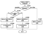
<状況確認ボタン選択シーケンス>
次に、図14を参照して、図11の拡張アプリ画面1100における状況確認ボタン405を選択した場合のシーケンスについて説明する。以下で説明する処理は、例えば、CPU101がROM103やストレージ104に格納されたプログラムをRAM102に読み出して実行することによって実現される。
<Status confirmation button selection sequence>
Next, a sequence when the
まず、S1401で、UI制御部301は、ユーザによる画面操作を検知する。続いて、S1402で、UI制御部301は、操作情報通知処理により、いずれに操作情報を通知するかを決定する。この場合、フッター領域407内にある状況確認ボタン405が選択(操作)されたため、S903の判定処理で通知先が標準機能制御部302に決定される。その後、S1403で、UI制御部301は、操作情報を標準機能制御部302に通知する。
First, in step S1401, the
S1404で、標準機能制御部302は、現在表示している画面と、受信した操作情報とに基づき、どのような操作が行われたかを識別する操作識別処理を実行する。ここでは状況確認ボタン405が選択されたことが識別される。続いて、S1405で、標準機能制御部302は、状況確認ボタン405が選択されたため、図7に示す状況確認画面700の描画を行う。その後、S1406で、標準機能制御部302は、画面を表示するため画面出力要求送信処理を実行する。そしてS1407で、標準機能制御部302は、画面出力処理部304に優先出力要求を通知する。画面出力要求送信処理の詳細については図15を用いて後述する。
In step S <b> 1404, the standard
S1408で、画面出力処理部304は、優先出力要求を受け、標準機能用画面バッファの内容をアプリケーション用画面バッファよりも優先的に出力するために、画面の出力元を一時的に標準機能用画面バッファに切り替える画面切替処理を実行する。続いて、S1409で、切り替えた画面を表示するため、画面出力処理部304は、画面出力処理を実行する。この処理によって図11の画面から図7の画面に表示が切り替わる。
In step S1408, the screen
また、S1410で、標準機能制御部302は、次の操作情報を標準機能制御部302に送るように操作情報通知要求をUI制御部301へ送る。S1411で、UI制御部301は、操作情報通知要求を受けると、通知先切替処理を実行し、操作情報通知先を標準機能制御部302に切り替える。
In step S1410, the standard
次に、S1412で、ユーザが閉じるボタン706を選択した場合、UI制御部301は画面操作を検知する。続いて、S1413で、UI制御部301は、操作情報通知処理により、いずれに操作情報を通知するかを決定する。ここでは、S1411で通知先が標準機能制御部302に切り替えられているため、S1414で、UI制御部301は、操作情報を標準機能制御部302に通知する。
Next, when the user selects the
S1415で、標準機能制御部302は、現在表示している画面と、受信した操作情報とに基づき、どのような操作が行われたかを識別する操作識別処理を実行する。ここでは閉じるボタン706が選択されたことが識別される。続いて、S1416で、標準機能制御部302は、閉じるボタン706が選択されたため、図4に示すホーム画面400の描画を行う。S1417で、標準機能制御部302は、画面を表示するために画面出力要求送信処理を実行する。そしてS1418で、標準機能制御部302は、優先出力を解除するため優先出力解除を画面出力処理部304へ送り、S1421で操作情報通知の解除要求をUI制御部301へ送る。画面出力要求送信処理の詳細については図15を用いて後述する。
In step S1415, the standard
優先出力解除を受けた画面出力処理部304は、S1419で、画面切替処理を実行し、画面出力元を元のアプリケーション用画面バッファに切り替える。続いて、S1420で、画面出力処理部304は、図11の拡張アプリ画面1100を操作部112に表示するため画面出力処理を実行する。
In step S1419, the screen
また、標準機能制御部302は、操作情報通知の解除要求を受けると、S1422で、通知先切替処理を実行し、情報通知先をアプリケーション管理部305、即ち、拡張アプリケーションに切り替える。
When the standard
上述したように、拡張アプリ画面のフッター領域407への操作を検知した際に、標準機能制御部302による画面遷移が発生するような場合には、当該画面(ネイティブプログラムの画面)へ表示を切り替えることができる。さらに、当該画面においてユーザ操作によって戻る操作が行われた場合には、元の拡張アプリ画面へ戻ることができる。
As described above, when a screen transition by the standard
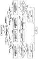
<画面出力要求送信処理>
次に、図15を参照して、図5、図12、図14の画面出力要求送信処理(S5006、S1202、S1406、S1417)の詳細な処理手順について説明する。以下で説明する処理は、例えば、CPU101がROM103やストレージ104に格納されたプログラムをRAM102に読み出して実行することによって実現される。
<Screen output request transmission processing>
Next, a detailed processing procedure of the screen output request transmission processing (S5006, S1202, S1406, S1417) of FIGS. 5, 12, and 14 will be described with reference to FIG. The processing described below is realized, for example, when the
まず、S1501で、標準機能制御部302は、出力しようとしている画面が画面遷移によるものなのか、画面の部分更新によるものなのかを判定する。ここで、画面遷移である場合はS1502に進み、部分更新である場合はS1507に進む。S1502で、標準機能制御部302は、画面遷移の種類がホーム画面400への遷移かどうかを判定する。ホーム画面400への遷移である場合はS1505に進み、ホーム画面400への遷移でない場合はS1503に進む。
First, in step S1501, the standard
S1503で、標準機能制御部302は、画面出力処理部304で標準機能用画面バッファが表示されるように、優先出力表示要求の送信を行う。続いて、S1504で、標準機能制御部302は、UI制御部301の操作情報の通知先が標準機能制御部302になるように、入力切替要求の送信をUI制御部301に対して行い、処理を終了する。
In step S1503, the standard
一方、S1505で、標準機能制御部302は、アプリケーションが実行中の場合にアプリケーション用画面バッファが表示されるように、優先出力解除要求の送信を画面出力処理部304に対して行う。続いて、S1506で、標準機能制御部302は、アプリケーションが実行中の場合にアプリケーションに操作情報が通知されるように、入力切替要求の送信をUI制御部301に対して行い、処理を終了する。
On the other hand, in step S1505, the standard
また、S1507で、標準機能制御部302は、表示画面を更新するために、画面出力要求の送信を画面出力処理部304に対して行い、処理を終了する。本フローチャートの処理を実行することにより、状況に応じて表示画面の切り替えと、操作情報の通知先を切り替えることができる。
In step S1507, the standard
<通知先切替処理>
次に、図16を参照して、図8及び図14の通知先切替処理(S8013、S1411、S1422)の詳細な処理手順について説明する。以下で説明する処理は、例えば、CPU101がROM103やストレージ104に格納されたプログラムをRAM102に読み出して実行することによって実現される。
<Notification destination switching process>
Next, a detailed processing procedure of the notification destination switching processing (S8013, S1411, S1422) of FIGS. 8 and 14 will be described with reference to FIG. The processing described below is realized, for example, when the
まず、S1601で、UI制御部301は、切替処理の要求元が標準機能制御部302(ネイティブプログラム)であるか、又はアプリケーション実行制御部306(拡張アプリケーション)であるかを判定する。切替処理の要求元が標準機能制御部302の場合はS1608に進み、要求元がアプリケーション実行制御部306の場合はS1602に進む。
First, in step S1601, the
S1602で、UI制御部301は、切替処理要求が通知要求か解除要求かを判定する。通知要求の場合はS1603に進み、解除要求の場合はS1606に進む。S1603で、UI制御部301は、アプリケーションへの操作情報通知フラグを有効にセットする。このフラグはデフォルトでは無効にセットされている。続いて、S1604で、UI制御部301は、標準機能制御部302の操作情報通知フラグを確認する。通知有効の場合はそのまま処理を終了し、無効の場合はS1605に進む。S1605で、UI制御部301は、操作情報通知対象をアプリケーション管理部305に設定し、処理を終了する。なお、操作情報通知対象は、デフォルトで標準機能制御部302にセットされている。
In step S1602, the
一方、S1606で、UI制御部301は、アプリケーションへの操作情報通知フラグを無効にセットする。続いて、S1607で、UI制御部301は、操作情報通知対象を標準機能制御部302に設定し、処理を終了する。
On the other hand, in step S1606, the
一方、S1608で、UI制御部301は、S1602と同様に、切替要求が通知要求か解除要求かを判定する。通知要求の場合はS1609に進み、解除要求の場合はS1611に進む。S1609で、UI制御部301は、標準機能制御部302の操作情報通知フラグを有効にセットする。このフラグはデフォルトで無効にセットされている。続いて、S1610で、UI制御部301は、操作情報通知対象を標準機能制御部302に設定し、処理を終了する。
On the other hand, in S1608, the
一方、S1611で、UI制御部301は、標準機能制御部302の操作情報通知フラグを無効にセットする。続いて、S1612で、UI制御部301は、アプリケーションへの操作情報通知フラグの設定状態を確認する。有効に設定されている場合はS1613に進み、無効に設定されている場合は、処理を終了する。S1613で、UI制御部301は、操作情報通知対象をアプリケーション管理部305に設定して、処理を終了する。本フローチャートの処理を実行することにより、状況に応じて操作情報をアプリケーション管理部305と標準機能制御部302とに切り分けて通知することができる。
On the other hand, in step S <b> 1611, the
<画像出力元切替処理>
次に、図17を参照して、図8及び図18の画面出力元切替処理(S8009、S1802)の詳細な処理手順について説明する。以下で説明する処理は、例えば、CPU101がROM103やストレージ104に格納されたプログラムをRAM102に読み出して実行することによって実現される。
<Image output source switching process>
Next, a detailed processing procedure of the screen output source switching processing (S8009, S1802) of FIGS. 8 and 18 will be described with reference to FIG. The processing described below is realized, for example, when the
まず、S1701で、画面出力処理部304は、画面出力元切替の要求元が標準機能制御部302(ネイティブプログラム)か又はアプリケーション実行制御部306(拡張アプリケーション)かを判定する。要求元が標準機能制御部302の場合はS1708に進み、要求元がアプリケーション実行制御部306の場合はS1702に進む。
First, in step S1701, the screen
S1702で、画面出力処理部304は、画面出力元切替要求の種類が出力要求か解除要求かを判定する。出力要求の場合はS1703に進み、解除要求の場合はS1706に進む。S1703で、画面出力処理部304は、アプリケーション用画面バッファからの出力フラグを有効にセットする。このフラグはデフォルトでは無効にセットされている。続いて、S1704で、画面出力処理部304は、標準機能用画面バッファからの出力フラグを確認する。有効の場合は処理を終了し、無効の場合はS1705に進む。S1705で、画面出力処理部304は、出力元をアプリケーション用画面バッファに設定し、処理を終了する。この出力元は、デフォルトで標準機能画面バッファにセットされている。
In step S1702, the screen
一方、S1706で、画面出力処理部304は、アプリケーション用画面バッファからの出力フラグを無効にセットする。続いて、S1707で、画面出力処理部304は、操作情報通知対象を標準機能制御部302に設定し、処理を終了する。
On the other hand, in step S1706, the screen
一方、S1708で、画面出力処理部304は、S1702と同様に、画面出力元切替要求が出力要求か解除要求かを判定する。出力要求の場合はS1709に進み、解除要求の場合はS1711に進む。S1709で、画面出力処理部304は、標準機能用画面バッファからの出力フラグを有効にセットする。このフラグはデフォルトで無効にセットされている。続いて、S1710で、画面出力処理部304は、操作情報通知対象を標準機能制御部302に設定し、処理を終了する。
On the other hand, in S1708, the screen
一方、S1711で、画面出力処理部304は、標準機能用画面バッファからの出力フラグを無効にセットする。続いて、S1712で、画面出力処理部304は、アプリケーション用画面バッファからの出力フラグの設定状態を確認する。有効に設定されている場合はS1713に進み、無効に設定されている場合は処理を終了する。S1713で、画面出力処理部304は、操作情報通知対象をアプリケーション管理部305に設定し、処理を終了する。本フローチャートの処理を実行することにより、状況に応じて出力する画面をアプリケーション用画面と標準機能用画面に切り分けることができる。
On the other hand, in step S1711, the screen
<アプリケーション終了シーケンス>
次に、図18を参照して、本実施形態に係るアプリケーション終了時のシーケンスについて説明する。以下で説明する処理は、例えば、CPU101がROM103やストレージ104に格納されたプログラムをRAM102に読み出して実行することによって実現される。
<Application termination sequence>
Next, a sequence at the end of the application according to the present embodiment will be described with reference to FIG. The processing described below is realized, for example, when the
アプリケーションが終了すると、S1801で、アプリケーション実行制御部306は、画面出力処理部304に対し出力解除要求を行う。さらに、S1804で、アプリケーション実行制御部306は、UI制御部301に対して操作情報通知解除要求を行い、S1805で、アプリケーション管理部305に対して終了通知を行う。
When the application ends, the application
S1802で、画面出力処理部304は、出力解除要求を受け、画面出力元切替処理を実行する。この処理で、標準機能画面バッファが画面出力元に切り替わる。続いて、S1803で、画面出力処理部304は、画面出力処理を実行し、元の画面を表示する。
In step S1802, the screen
一方、S1806で、UI制御部301は、操作情報通知解除要求を受け、通知先切替処理を実行する。この処理で操作情報通知先は標準機能制御部302に切り替わる。その後、S1807で、UI制御部301は、ユーザからの画面操作を検知する。操作を検知すると、S1808で、UI制御部301は、操作情報通知処理を実行し、S1809で、操作情報を標準機能制御部302に通知する。上述のシーケンスを実行することによって、アプリケーションが終了した際に、表示画面は標準機能制御用画面に切り替わり、標準機能制御が操作情報を受け取ることができる。つまり、ユーザはネイティブプログラムと拡張アプリケーションとの切り替わりを意識することなく操作を行うことができる。
On the other hand, in step S <b> 1806, the
以上説明したように、本画像形成装置は、標準機能の操作画面を描画する標準機能用画面バッファ制御部303と、拡張機能の操作画面を描画するアプリケーション用画面バッファ制御部307とを備える。さらに、本画像形成装置は、標準機能用画面バッファ制御部303又はアプリケーション用画面バッファ制御部307によって描画された操作画面を出力する。当該出力において、アプリケーション用画面バッファ制御部307によって描画された操作画面、即ち、拡張機能の操作画面を出力する場合には、標準機能の操作画面の一部(例えば、フッター領域)を、拡張機能の操作画面に組み込んで出力する。上記標準機能の操作画面の一部とは、例えば、フッター領域であり、画像形成装置の状態を表示する領域である。当該操作画面の一部が操作されると、その操作情報は、標準機能制御部302へ通知される。一方、当該操作画面の一部以外が操作されると、その操作情報は、アプリケーション管理部305へ送信される。このように、本実施形態によれば、画像形成装置の限られたリソースの消費を抑えつつ、標準機能を操作するUIと、拡張機能を操作するUIを好適に共存させることにより、ユーザの利便性を確保することができる。なお、上述の制御のほとんどが標準機能制御部302によって制御されるため、拡張アプリケーションを開発する際には、煩雑な画面制御を意識することなく、設計することができる。
As described above, the image forming apparatus includes the standard function screen
<その他の実施形態>
本発明は、上述の実施形態の1以上の機能を実現するプログラムを、ネットワーク又は記憶媒体を介してシステム又は装置に供給し、そのシステム又は装置のコンピュータにおける1つ以上のプロセッサーがプログラムを読出し実行する処理でも実現可能である。また、1以上の機能を実現する回路(例えば、ASIC)によっても実現可能である。
<Other embodiments>
The present invention supplies a program that realizes one or more functions of the above-described embodiments to a system or apparatus via a network or a storage medium, and one or more processors in a computer of the system or apparatus read and execute the program This process can be realized. It can also be realized by a circuit (for example, ASIC) that realizes one or more functions.
10:、画像形成装置、100:コントローラユニット、101:CPU、102:RAM、103:ROM、104:ストレージ、105:画像パスI/F、106:操作部I/F、107:システムバス、108:画像バス、110:ネットワークI/F、112:操作部、113:USBホストI/F、114:USBストレージ、120:デバイスI/F、170:スキャナ、180:スキャナ画像処理部、190:プリンタ画像処理部、195:プリンタ 10: Image forming apparatus 100: Controller unit 101: CPU 102: RAM 103: ROM 104: Storage 105: Image path I / F 106: Operation unit I / F 107: System bus 108 : Image bus, 110: Network I / F, 112: Operation unit, 113: USB host I / F, 114: USB storage, 120: Device I / F, 170: Scanner, 180: Scanner image processing unit, 190: Printer Image processing unit, 195: printer
Claims (12)
前記画像形成装置のネイティブプログラムを制御する第1制御手段と、
前記ネイティブプログラムとは異なる拡張アプリケーションを制御する第2制御手段と、
前記第1制御手段によって制御されるネイティブプログラムの操作画面を描画する第1バッファ制御手段と、
前記第2制御手段によって制御される拡張アプリケーションの操作画面を描画する第2バッファ制御手段と、
前記第1バッファ制御手段又は前記第2バッファ制御手段によって描画された操作画面を出力する出力処理手段と
を備え、
前記出力処理手段は、
前記第2バッファ制御手段によって描画された操作画面を出力する場合には、前記ネイティブプログラムの操作画面の一部を、前記拡張アプリケーションの操作画面に組み込んで出力することを特徴とする画像形成装置。 An image forming apparatus,
First control means for controlling a native program of the image forming apparatus;
Second control means for controlling an extended application different from the native program;
First buffer control means for drawing an operation screen of a native program controlled by the first control means;
Second buffer control means for drawing an operation screen of the extended application controlled by the second control means;
Output processing means for outputting an operation screen drawn by the first buffer control means or the second buffer control means,
The output processing means includes
When outputting the operation screen drawn by the second buffer control means, a part of the operation screen of the native program is incorporated into the operation screen of the extended application and output.
前記操作画面を介したユーザ操作を受け付けた際に、
前記ネイティブプログラムの操作画面が出力されている場合は操作情報を前記第1制御手段へ通知し、
前記拡張アプリケーションの操作画面が出力されている場合であって、かつ、組み込まれた前記ネイティブプログラムの操作画面の一部が操作された場合は操作情報を前記第1制御手段へ通知し、
前記拡張アプリケーションの操作画面が出力されている場合であって、かつ、組み込まれた前記ネイティブプログラムの操作画面の一部以外が操作された場合は操作情報を前記第2制御手段へ通知することを特徴とする請求項2に記載の画像形成装置。 The notification means includes
When receiving a user operation via the operation screen,
When the operation screen of the native program is output, the operation information is notified to the first control means,
When the operation screen of the extended application is output, and when a part of the operation screen of the embedded native program is operated, the operation information is notified to the first control means,
When the operation screen of the extended application is output and when a part other than the operation screen of the embedded native program is operated, the operation information is notified to the second control unit. The image forming apparatus according to claim 2.
前記拡張アプリケーションの操作画面が出力されている場合であって、かつ、組み込まれた前記ネイティブプログラムの操作画面の一部が操作された場合に通知された操作情報が画面遷移を伴う操作を示す場合、優先的に前記第1バッファ制御手段が描画する操作画面を出力するように要求する優先出力要求を前記出力処理手段へ通知することを特徴とする請求項3に記載の画像形成装置。 The first control means includes
When the operation screen of the extended application is output, and the operation information notified when a part of the operation screen of the embedded native program is operated indicates an operation involving screen transition 4. The image forming apparatus according to claim 3, wherein a priority output request for requesting to output an operation screen drawn by the first buffer control unit is preferentially notified to the output processing unit.
前記拡張アプリケーションの操作画面が出力されている場合であって、かつ、組み込まれた前記ネイティブプログラムの操作画面の一部が操作された場合に通知された操作情報が該ネイティブプログラムの操作画面の一部の更新を伴う操作を示す場合、当該操作画面の更新を前記第1バッファ制御手段へ通知することを特徴とする請求項3又は4に記載の画像形成装置。 The first control means includes
The operation information notified when the operation screen of the extended application is output and a part of the operation screen of the embedded native program is operated is one of the operation screens of the native program. 5. The image forming apparatus according to claim 3, wherein an update of the operation screen is notified to the first buffer control unit when an operation accompanied by an update of a part is indicated.
前記優先出力要求を通知した後に、前記通知手段によって通知された操作情報が元の画面へ遷移する操作を示す場合、該優先出力要求を解除するように前記出力処理手段へ要求することを特徴とする請求項4に記載の画像形成装置。 The first control means includes
After the notification of the priority output request, when the operation information notified by the notification means indicates an operation to change to the original screen, the output processing means is requested to cancel the priority output request. The image forming apparatus according to claim 4.
前記ネイティブプログラムの操作画面が出力されている場合に、前記通知手段によって通知された操作情報が前記拡張アプリケーションを起動する操作を示す場合、前記第2バッファ制御手段が描画する操作画面を出力するように要求する切替要求を前記出力処理手段へ通知することを特徴とする請求項3に記載の画像形成装置。 The first control means includes
When the operation screen of the native program is output and the operation information notified by the notification means indicates an operation for starting the extended application, the operation screen drawn by the second buffer control means is output. The image forming apparatus according to claim 3, wherein the output processing unit is notified of a switching request to be requested.
前記切替要求が通知された後に、前記拡張アプリケーションが終了すると、前記切替要求を解除するように前記出力処理手段へ要求することを特徴とする請求項7に記載の画像形成装置。 The second control means includes
8. The image forming apparatus according to claim 7, wherein when the extended application is terminated after the switching request is notified, the output processing unit is requested to cancel the switching request.
第1制御手段が、前記画像形成装置のネイティブプログラムを制御する第1制御工程と、
第2制御手段が、前記ネイティブプログラムとは異なる拡張アプリケーションを制御する第2制御工程と、
第1バッファ制御手段が、前記第1制御工程で制御されるネイティブプログラムの操作画面を描画する第1バッファ制御工程と、
第2バッファ制御手段が、前記第2制御工程で制御される拡張アプリケーションの操作画面を描画する第2バッファ制御工程と、
出力処理手段が、前記第1バッファ制御工程又は前記第2バッファ制御工程で描画された操作画面を出力する出力処理工程と
を実行し、
前記出力処理工程において、
前記第2バッファ制御工程で描画された操作画面を出力する場合には、前記ネイティブプログラムの操作画面の一部を、前記拡張アプリケーションの操作画面に組み込んで出力することを特徴とする画像形成装置の制御方法。 An image forming apparatus control method comprising:
A first control unit that controls a native program of the image forming apparatus;
A second control step in which a second control means controls an extended application different from the native program;
A first buffer control step in which a first buffer control means draws an operation screen of a native program controlled in the first control step;
A second buffer control step, wherein the second buffer control means draws an operation screen of the extended application controlled in the second control step;
An output processing means for executing an output processing step for outputting the operation screen drawn in the first buffer control step or the second buffer control step;
In the output processing step,
When outputting the operation screen drawn in the second buffer control step, a part of the operation screen of the native program is incorporated into the operation screen of the extended application and output. Control method.
第1制御手段が、前記画像形成装置のネイティブプログラムを制御する第1制御工程と、
第2制御手段が、前記ネイティブプログラムとは異なる拡張アプリケーションを制御する第2制御工程と、
第1バッファ制御手段が、前記第1制御工程で制御されるネイティブプログラムの操作画面を描画する第1バッファ制御工程と、
第2バッファ制御手段が、前記第2制御工程で制御される拡張アプリケーションの操作画面を描画する第2バッファ制御工程と、
出力処理手段が、前記第1バッファ制御工程又は前記第2バッファ制御工程で描画された操作画面を出力する出力処理工程と
を実行し、
前記出力処理工程において、
前記第2バッファ制御工程で描画された操作画面を出力する場合には、前記ネイティブプログラムの操作画面の一部を、前記拡張アプリケーションの操作画面に組み込んで出力することを特徴とするプログラム。 A program for causing a computer to execute each step in a control method of an image forming apparatus, wherein the control method includes:
A first control unit that controls a native program of the image forming apparatus;
A second control step in which a second control means controls an extended application different from the native program;
A first buffer control step in which a first buffer control means draws an operation screen of a native program controlled in the first control step;
A second buffer control step, wherein the second buffer control means draws an operation screen of the extended application controlled in the second control step;
An output processing means for executing an output processing step for outputting the operation screen drawn in the first buffer control step or the second buffer control step;
In the output processing step,
When outputting the operation screen drawn in the second buffer control step, a part of the operation screen of the native program is incorporated into the operation screen of the extended application and output.
Priority Applications (3)
| Application Number | Priority Date | Filing Date | Title |
|---|---|---|---|
| JP2016156859A JP6784537B2 (en) | 2016-08-09 | 2016-08-09 | Image forming device, its control method, and program |
| US15/660,058 US10694058B2 (en) | 2016-08-09 | 2017-07-26 | Image forming apparatus that outputs an operation screen of an extension application with part of an operation screen of a native program control method therefor, and storage medium |
| US16/872,577 US11115547B2 (en) | 2016-08-09 | 2020-05-12 | Image forming apparatus that notifies a specific control unit of operation information depending on an operation screen being displayed, and control method therefor |
Applications Claiming Priority (1)
| Application Number | Priority Date | Filing Date | Title |
|---|---|---|---|
| JP2016156859A JP6784537B2 (en) | 2016-08-09 | 2016-08-09 | Image forming device, its control method, and program |
Publications (3)
| Publication Number | Publication Date |
|---|---|
| JP2018024151A true JP2018024151A (en) | 2018-02-15 |
| JP2018024151A5 JP2018024151A5 (en) | 2019-09-12 |
| JP6784537B2 JP6784537B2 (en) | 2020-11-11 |
Family
ID=61159613
Family Applications (1)
| Application Number | Title | Priority Date | Filing Date |
|---|---|---|---|
| JP2016156859A Active JP6784537B2 (en) | 2016-08-09 | 2016-08-09 | Image forming device, its control method, and program |
Country Status (2)
| Country | Link |
|---|---|
| US (2) | US10694058B2 (en) |
| JP (1) | JP6784537B2 (en) |
Families Citing this family (6)
| Publication number | Priority date | Publication date | Assignee | Title |
|---|---|---|---|---|
| JP6861670B2 (en) | 2018-07-10 | 2021-04-21 | キヤノン株式会社 | Image processing device, its control method, and program |
| JP7105640B2 (en) | 2018-07-10 | 2022-07-25 | キヤノン株式会社 | IMAGE PROCESSING DEVICE, CONTROL METHOD THEREOF, AND PROGRAM |
| JP2021012668A (en) * | 2019-07-09 | 2021-02-04 | 株式会社リコー | Information processing equipment, methods, and programs |
| JP7545277B2 (en) * | 2020-09-25 | 2024-09-04 | シャープ株式会社 | Image processing device, image processing system including the image processing device, and control program and control method for the image processing device |
| JP7512174B2 (en) | 2020-11-16 | 2024-07-08 | キヤノン株式会社 | Image forming apparatus, display device and control method thereof, |
| JP7585249B2 (en) * | 2022-02-09 | 2024-11-18 | キヤノン株式会社 | PROGRAM, INFORMATION PROCESSING APPARATUS AND CONTROL METHOD |
Citations (6)
| Publication number | Priority date | Publication date | Assignee | Title |
|---|---|---|---|---|
| JP2002055805A (en) * | 2000-08-07 | 2002-02-20 | Digital Electronics Corp | Graphic operation panel, recording medium recording program for the panel and extending unit |
| JP2011141683A (en) * | 2010-01-06 | 2011-07-21 | Ricoh Co Ltd | Image processing apparatus, display device, authentication system, display control method, display control program and recording medium recording the same |
| JP2011245763A (en) * | 2010-05-27 | 2011-12-08 | Ricoh Co Ltd | Image processing device, display device, screen control system, screen control method, screen control program, and recording medium with the program recorded thereon |
| JP2013145503A (en) * | 2012-01-16 | 2013-07-25 | Canon Inc | Device, control method, and program |
| US20150286451A1 (en) * | 2014-04-03 | 2015-10-08 | Canon Kabushiki Kaisha | Methods and systems for managing a print-setting user interface |
| WO2015182303A1 (en) * | 2014-05-30 | 2015-12-03 | 京セラドキュメントソリューションズ株式会社 | Image formation device and image formation method |
Family Cites Families (10)
| Publication number | Priority date | Publication date | Assignee | Title |
|---|---|---|---|---|
| JP3826069B2 (en) * | 2002-05-17 | 2006-09-27 | キヤノン株式会社 | Image forming apparatus, control method, and control program |
| JP4405939B2 (en) * | 2005-05-18 | 2010-01-27 | キヤノン株式会社 | Image processing apparatus, control method therefor, and image processing system |
| JP4612863B2 (en) * | 2005-05-18 | 2011-01-12 | キヤノン株式会社 | Image processing apparatus and control method and program thereof |
| JP5497989B2 (en) * | 2008-02-20 | 2014-05-21 | キヤノン株式会社 | Information processing apparatus, control method thereof, and program |
| JP5235540B2 (en) * | 2008-07-11 | 2013-07-10 | キヤノン株式会社 | Information processing system, information processing apparatus, information processing method, and program |
| JP5075240B2 (en) * | 2010-08-27 | 2012-11-21 | シャープ株式会社 | Operation device, image processing device, and display method |
| JP6091142B2 (en) | 2012-10-05 | 2017-03-08 | キヤノン株式会社 | Image forming apparatus, control method, and program thereof. |
| JP2015046075A (en) * | 2013-08-29 | 2015-03-12 | キヤノン株式会社 | Information processing apparatus, control method therefor, and computer program |
| JP6849385B2 (en) * | 2016-10-18 | 2021-03-24 | キヤノン株式会社 | Image processing equipment, information processing methods and programs |
| JP6801544B2 (en) * | 2017-03-22 | 2020-12-16 | 株式会社リコー | Information processing equipment, information processing methods and programs |
-
2016
- 2016-08-09 JP JP2016156859A patent/JP6784537B2/en active Active
-
2017
- 2017-07-26 US US15/660,058 patent/US10694058B2/en active Active
-
2020
- 2020-05-12 US US16/872,577 patent/US11115547B2/en active Active
Patent Citations (6)
| Publication number | Priority date | Publication date | Assignee | Title |
|---|---|---|---|---|
| JP2002055805A (en) * | 2000-08-07 | 2002-02-20 | Digital Electronics Corp | Graphic operation panel, recording medium recording program for the panel and extending unit |
| JP2011141683A (en) * | 2010-01-06 | 2011-07-21 | Ricoh Co Ltd | Image processing apparatus, display device, authentication system, display control method, display control program and recording medium recording the same |
| JP2011245763A (en) * | 2010-05-27 | 2011-12-08 | Ricoh Co Ltd | Image processing device, display device, screen control system, screen control method, screen control program, and recording medium with the program recorded thereon |
| JP2013145503A (en) * | 2012-01-16 | 2013-07-25 | Canon Inc | Device, control method, and program |
| US20150286451A1 (en) * | 2014-04-03 | 2015-10-08 | Canon Kabushiki Kaisha | Methods and systems for managing a print-setting user interface |
| WO2015182303A1 (en) * | 2014-05-30 | 2015-12-03 | 京セラドキュメントソリューションズ株式会社 | Image formation device and image formation method |
Also Published As
| Publication number | Publication date |
|---|---|
| US10694058B2 (en) | 2020-06-23 |
| US20200274981A1 (en) | 2020-08-27 |
| JP6784537B2 (en) | 2020-11-11 |
| US20180048776A1 (en) | 2018-02-15 |
| US11115547B2 (en) | 2021-09-07 |
Similar Documents
| Publication | Publication Date | Title |
|---|---|---|
| JP6784537B2 (en) | Image forming device, its control method, and program | |
| US10165145B2 (en) | Image processing apparatus, method for controlling image processing apparatus, and storage medium | |
| JP4448060B2 (en) | Copying apparatus, control method therefor, program for executing the method, and copying system | |
| US9135360B2 (en) | Information transmission apparatus, control method thereof, and recording medium storing computer program | |
| US8390861B2 (en) | Information processing apparatus, method, and recording medium controlling the display of printing options | |
| JP2020004158A (en) | Information processing apparatus, control method for information processing apparatus, and program | |
| US20120268778A1 (en) | Print relay system, printing system, image forming apparatus, method for controlling print relay system, and program | |
| JP6071273B2 (en) | Image forming apparatus, control method therefor, and program | |
| JP7240246B2 (en) | IMAGE FORMING APPARATUS, CONTROL METHOD AND IMAGE FORMING SYSTEM THEREOF, AND PROGRAM | |
| US8988699B2 (en) | Device, information processing apparatus, information processing system, control method, and program | |
| EP4224306B1 (en) | Server apparatus, control method therefor, and storage medium storing control program therefor | |
| JP2018025909A (en) | Information processing apparatus, method for controlling apparatus, and control program for executing method | |
| JP6628654B2 (en) | Information processing apparatus, print plug-in, print system, and control method | |
| US10331388B2 (en) | Image processing system, image processing method, and non-transitory storage medium storing image processing program | |
| US8976389B2 (en) | Printing apparatus for transmitting information printing method thereof, and storage medium | |
| WO2012144164A1 (en) | Printing system, print relay server, method of controlling the server, and program | |
| US20180063367A1 (en) | Information processing system, information processing apparatus, information processing method, and information processing program | |
| JP2018015947A (en) | Image formation apparatus, image formation method and program | |
| US9794437B2 (en) | Information processing apparatus, information processing system, and information processing method | |
| JP7638726B2 (en) | Image forming apparatus, control method, program, and storage medium | |
| JP2018055184A (en) | Image forming apparatus and program | |
| US9942425B2 (en) | Image processing apparatus, information processing apparatus, and medium that selectively provide prompts to confirm orientation | |
| US10785376B2 (en) | Image processing apparatus for sending user interface data | |
| JP2018101915A (en) | Image forming apparatus capable of mounting application and control method thereof | |
| JP2016009995A (en) | Image processing apparatus, image processing system, information processing method, and program |
Legal Events
| Date | Code | Title | Description |
|---|---|---|---|
| A521 | Request for written amendment filed |
Free format text: JAPANESE INTERMEDIATE CODE: A523 Effective date: 20190805 |
|
| A621 | Written request for application examination |
Free format text: JAPANESE INTERMEDIATE CODE: A621 Effective date: 20190805 |
|
| TRDD | Decision of grant or rejection written | ||
| A01 | Written decision to grant a patent or to grant a registration (utility model) |
Free format text: JAPANESE INTERMEDIATE CODE: A01 Effective date: 20200925 |
|
| A61 | First payment of annual fees (during grant procedure) |
Free format text: JAPANESE INTERMEDIATE CODE: A61 Effective date: 20201023 |
|
| R151 | Written notification of patent or utility model registration |
Ref document number: 6784537 Country of ref document: JP Free format text: JAPANESE INTERMEDIATE CODE: R151 |