JP2018024152A - Image processing apparatus and recording data generation method - Google Patents
Image processing apparatus and recording data generation method Download PDFInfo
- Publication number
- JP2018024152A JP2018024152A JP2016156868A JP2016156868A JP2018024152A JP 2018024152 A JP2018024152 A JP 2018024152A JP 2016156868 A JP2016156868 A JP 2016156868A JP 2016156868 A JP2016156868 A JP 2016156868A JP 2018024152 A JP2018024152 A JP 2018024152A
- Authority
- JP
- Japan
- Prior art keywords
- pixel
- processing
- nozzle
- recording
- pixels
- Prior art date
- Legal status (The legal status is an assumption and is not a legal conclusion. Google has not performed a legal analysis and makes no representation as to the accuracy of the status listed.)
- Granted
Links
Images


Classifications
-
- B—PERFORMING OPERATIONS; TRANSPORTING
- B41—PRINTING; LINING MACHINES; TYPEWRITERS; STAMPS
- B41J—TYPEWRITERS; SELECTIVE PRINTING MECHANISMS, i.e. MECHANISMS PRINTING OTHERWISE THAN FROM A FORME; CORRECTION OF TYPOGRAPHICAL ERRORS
- B41J2/00—Typewriters or selective printing mechanisms characterised by the printing or marking process for which they are designed
- B41J2/005—Typewriters or selective printing mechanisms characterised by the printing or marking process for which they are designed characterised by bringing liquid or particles selectively into contact with a printing material
- B41J2/01—Ink jet
- B41J2/015—Ink jet characterised by the jet generation process
- B41J2/04—Ink jet characterised by the jet generation process generating single droplets or particles on demand
- B41J2/045—Ink jet characterised by the jet generation process generating single droplets or particles on demand by pressure, e.g. electromechanical transducers
- B41J2/04501—Control methods or devices therefor, e.g. driver circuits, control circuits
- B41J2/04508—Control methods or devices therefor, e.g. driver circuits, control circuits aiming at correcting other parameters
-
- B—PERFORMING OPERATIONS; TRANSPORTING
- B41—PRINTING; LINING MACHINES; TYPEWRITERS; STAMPS
- B41J—TYPEWRITERS; SELECTIVE PRINTING MECHANISMS, i.e. MECHANISMS PRINTING OTHERWISE THAN FROM A FORME; CORRECTION OF TYPOGRAPHICAL ERRORS
- B41J2/00—Typewriters or selective printing mechanisms characterised by the printing or marking process for which they are designed
- B41J2/005—Typewriters or selective printing mechanisms characterised by the printing or marking process for which they are designed characterised by bringing liquid or particles selectively into contact with a printing material
- B41J2/01—Ink jet
- B41J2/21—Ink jet for multi-colour printing
- B41J2/2132—Print quality control characterised by dot disposition, e.g. for reducing white stripes or banding
- B41J2/2146—Print quality control characterised by dot disposition, e.g. for reducing white stripes or banding for line print heads
-
- B—PERFORMING OPERATIONS; TRANSPORTING
- B41—PRINTING; LINING MACHINES; TYPEWRITERS; STAMPS
- B41J—TYPEWRITERS; SELECTIVE PRINTING MECHANISMS, i.e. MECHANISMS PRINTING OTHERWISE THAN FROM A FORME; CORRECTION OF TYPOGRAPHICAL ERRORS
- B41J2/00—Typewriters or selective printing mechanisms characterised by the printing or marking process for which they are designed
- B41J2/005—Typewriters or selective printing mechanisms characterised by the printing or marking process for which they are designed characterised by bringing liquid or particles selectively into contact with a printing material
- B41J2/01—Ink jet
- B41J2/21—Ink jet for multi-colour printing
- B41J2/2132—Print quality control characterised by dot disposition, e.g. for reducing white stripes or banding
- B41J2/2139—Compensation for malfunctioning nozzles creating dot place or dot size errors
-
- B—PERFORMING OPERATIONS; TRANSPORTING
- B41—PRINTING; LINING MACHINES; TYPEWRITERS; STAMPS
- B41J—TYPEWRITERS; SELECTIVE PRINTING MECHANISMS, i.e. MECHANISMS PRINTING OTHERWISE THAN FROM A FORME; CORRECTION OF TYPOGRAPHICAL ERRORS
- B41J2/00—Typewriters or selective printing mechanisms characterised by the printing or marking process for which they are designed
- B41J2/005—Typewriters or selective printing mechanisms characterised by the printing or marking process for which they are designed characterised by bringing liquid or particles selectively into contact with a printing material
- B41J2/01—Ink jet
- B41J2/015—Ink jet characterised by the jet generation process
- B41J2/04—Ink jet characterised by the jet generation process generating single droplets or particles on demand
- B41J2/045—Ink jet characterised by the jet generation process generating single droplets or particles on demand by pressure, e.g. electromechanical transducers
- B41J2/04501—Control methods or devices therefor, e.g. driver circuits, control circuits
- B41J2/04586—Control methods or devices therefor, e.g. driver circuits, control circuits controlling heads of a type not covered by groups B41J2/04575 - B41J2/04585, or of an undefined type
Landscapes
- Engineering & Computer Science (AREA)
- Quality & Reliability (AREA)
- Ink Jet (AREA)
Abstract
【課題】記録データ生成において、不吐出補完のための処理時間をより短くすることを可能とする。【解決手段】それぞれインクを吐出する複数のノズルを配列したノズル列によって記録媒体の所定領域を記録するための記録データの生成を行う画像処理装置は、所定領域の記録データにおいて、ノズルの配列方向またはその配列方向と直交する直交方向の画素列のそれぞれの画素について、その画素を記録するノズルが不吐出である場合は、その画素を記録可能な他のノズルで記録するよう、補完処理を行う補完処理部、を具え、補完処理部は、配列方向または直交方向における画素列を、その画素列の所定数ごとの画素からなる処理グループに分け、分けられた複数の処理グループについて順次に補完処理を行うとともに、それぞれの処理グループにおける画素に対する補完処理を並列処理として行う。【選択図】図6In recording data generation, it is possible to further shorten the processing time for non-ejection compensation. An image processing apparatus for generating recording data for recording a predetermined area of a recording medium by a nozzle array in which a plurality of nozzles each ejecting ink is arranged. Alternatively, for each pixel in the pixel row in the orthogonal direction orthogonal to the arrangement direction, if the nozzle that records the pixel is non-ejection, complement processing is performed so that the pixel is recorded by another nozzle that can record the pixel. A complementary processing unit, and the complementary processing unit divides the pixel columns in the arrangement direction or the orthogonal direction into processing groups each including a predetermined number of pixels of the pixel columns, and sequentially performs the complementary processing on the plurality of divided processing groups. And complement processing for pixels in each processing group is performed as parallel processing. [Selection] Figure 6
Description
本発明は、画像処理装置および記録データ生成方法に関し、詳しくは、記録ヘッドの吐出不良ノズルの記録データを補完する処理に関する。 The present invention relates to an image processing apparatus and a print data generation method, and more particularly, to a process of complementing print data of ejection failure nozzles of a print head.
インクジェット記録ヘッドにおける吐出不良ノズルの記録データを補完する、所謂、不吐出補完として、例えば、特許文献1には、吐出不良が発生したノズルがインクを吐出して記録すべきドットの記録を近傍の他のノズルで記録する方法が記載されている。このような不吐出補完では、複数の、補完を行う候補ノズルの中から1つのノズルを選択し、その選択されたノズルから補完のためのインク吐出を行う。
As so-called non-discharge complementation, which complements the recording data of defective ejection nozzles in an ink jet recording head, for example,
ところで、複数の候補ノズルから補完するノズルを選択する場合、選択後のノズルと記録データの関係において、複数のノズルが隣接した配列で記録を行ったり、1つのノズルが連続して記録を行ったりしないように選択することが望ましい。 By the way, when a complementary nozzle is selected from a plurality of candidate nozzles, in the relationship between the selected nozzle and the recording data, recording is performed in an array in which a plurality of nozzles are adjacent, or one nozzle performs recording continuously. It is desirable to choose not to.
例えば、記録ヘッドのインクの吐出周波数を高くするとともに、記録媒体の搬送速度を増して記録装置全体の記録速度を大きくすることが行われている。そして、吐出周波数を高くすることは、同じ種類のインクについて上記搬送方向に複数のノズル列を配列することによって実現することができる。すなわち、1つのノズル列における各ノズルの吐出周波数を高くすることなく、複数のノズル列全体で擬似的に吐出周波数を高くすることができる。そして、この形態では、ある面積の画像を記録す際、複数のノズル列のそれぞれ(のノズル)が上記面積の画素配列に対して上記搬送方向において分散して用いられるように記録データが生成される。これにより、1つのノズルの吐出周波数を高くすることなく、上記擬似的に吐出周波数の高い、つまり解像度の高い記録を行うことが可能となる。このため、不吐出補完では、それぞれのノズル列について、候補ノズルの選択によって、搬送方向に隣接する複数のノズルが存在しないようにして、上記搬送方向における分散したノズルの使用を実現することが求められている。 For example, while increasing the ink ejection frequency of the recording head and increasing the recording medium conveyance speed, the recording speed of the entire recording apparatus is increased. Further, increasing the ejection frequency can be realized by arranging a plurality of nozzle rows in the transport direction for the same type of ink. That is, it is possible to increase the ejection frequency in a pseudo manner throughout the plurality of nozzle arrays without increasing the ejection frequency of each nozzle in one nozzle array. In this embodiment, when an image of a certain area is recorded, print data is generated so that each (nozzle) of the plurality of nozzle rows is dispersedly used in the transport direction with respect to the pixel array of the area. The As a result, it is possible to perform recording with a pseudo high ejection frequency, that is, high resolution without increasing the ejection frequency of one nozzle. For this reason, in non-ejection complementation, it is required to realize the use of dispersed nozzles in the transport direction so that there is no plurality of nozzles adjacent in the transport direction by selecting candidate nozzles for each nozzle row. It has been.
また、ノズル列について、そのノズル配列方向に隣接した複数のノズルからインクを吐出する場合はノズル間のクロストークが問題となる場合がある。このため、上記候補ノズルの選択によって、隣接する複数のノズルからインクを吐出する記録データとならないようにすることも求められている。 In addition, when ink is ejected from a plurality of nozzles adjacent to each other in the nozzle array direction, crosstalk between the nozzles may be a problem. For this reason, it is also required to prevent recording data from ejecting ink from a plurality of adjacent nozzles by selecting the candidate nozzles.
不吐出補完によって、上述のような、隣接したノズルが連続して吐出することや、1つのノズルが連続して吐出することを回避するには、補完対象ノズルで記録する画素に隣接する画素列の吐出データを参照する必要がある。このため、隣接ノズルの不吐出補完処理が終了してからでないと、次のノズルの不吐出補完処理が行えないことになる。すなわち、補完対象ノズルについて、順次の処理が行われることになる。 In order to avoid the continuous discharge of adjacent nozzles or the continuous discharge of one nozzle as described above by non-discharge complementation, the pixel row adjacent to the pixels to be recorded by the complement target nozzles It is necessary to refer to the discharge data. For this reason, the non-ejection complement process for the next nozzle cannot be performed until the non-ejection complement process for the adjacent nozzle is completed. That is, sequential processing is performed on the complement target nozzles.
しかしながら、補完対象ノズルについて上記のように順次の処理が行われる形態では、補完対象ノズルに関して前の画素の処理が終了してから次の画素の処理を行うことから、不吐出補完のための処理時間が比較的長くなるという問題がある。 However, in the embodiment in which the sequential processing is performed on the complement target nozzle as described above, the processing for the next pixel is performed after the processing of the previous pixel is completed with respect to the complement target nozzle. There is a problem that the time is relatively long.
本発明は、不吐出補完のための処理時間をより短くすることが可能な画像処理装置および記録データ生成方法を提供することを目的とする。 An object of the present invention is to provide an image processing apparatus and a recording data generation method capable of shortening the processing time for non-ejection compensation.
上記目的を達成するために本発明は、それぞれインクを吐出する複数のノズルを配列したノズル列によって記録媒体の所定領域を記録するための記録データの生成を行う画像処理装置であって、前記所定領域の記録データにおいて、前記ノズルの配列方向または該配列方向と直交する直交方向の画素列のそれぞれの画素について、当該画素を記録するノズルが不吐出である場合は、当該画素を記録可能な他のノズルで記録するよう、補完処理を行う補完手段、を具え、前記補完手段は、前記配列方向または前記直交方向における前記画素列を、当該画素列の所定数おきの画素からなる処理グループに分け、複数の前記処理グループについて順次に補完処理を行うとともに、それぞれの前記処理グループにおける画素に対する補完処理を並列処理として行うことを特徴とする。 In order to achieve the above object, the present invention provides an image processing apparatus for generating recording data for recording a predetermined area of a recording medium by a nozzle array in which a plurality of nozzles each ejecting ink are arranged. In the recording data of the area, for each pixel in the pixel array in the nozzle arrangement direction or in the orthogonal direction orthogonal to the arrangement direction, if the nozzle that records the pixel does not discharge, Complementing means for performing a complementing process so that recording is performed by the nozzles of the nozzles, and the complementing means divides the pixel columns in the arrangement direction or the orthogonal direction into processing groups composed of every predetermined number of pixels of the pixel columns. The complementary processing is sequentially performed on the plurality of processing groups, and the complementary processing for the pixels in each processing group is performed in parallel. And performing a.
以上の構成によれば、記録データ生成において、不吐出補完のための処理時間をより短くすることが可能となる。 According to the above configuration, it is possible to shorten the processing time for non-ejection complementation in print data generation.
以下、添付の図面を参照して本発明の実施形態を詳細に説明する。 Hereinafter, embodiments of the present invention will be described in detail with reference to the accompanying drawings.
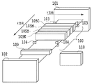
図1は、本発明の一実施形態に係るインクジェットプリンタ(記録装置)を模式的に示す斜視図である。本実施形態のプリンタは、ノズルを搬送されるシート(記録媒体)の幅に対応して配列したフルラインヘッドを用いたものである。本実施形態のプリンタは比較的高速の記録が可能であり、例えば、プリントラボ等における大量の枚数のプリントの分野に適している。 FIG. 1 is a perspective view schematically showing an ink jet printer (recording apparatus) according to an embodiment of the present invention. The printer of this embodiment uses a full line head arranged in correspondence with the width of a sheet (recording medium) conveyed with nozzles. The printer according to the present embodiment is capable of recording at a relatively high speed, and is suitable for the field of printing a large number of sheets, for example, in a print laboratory.
図1に示すように、本実施形態のプリンタは、シート供給部101、プリント部100、定着部109、排出部102の各ユニットを備える。シート紙供給部101はロール状に巻かれた、記録媒体としての連続シートを収納して供給する。
As shown in FIG. 1, the printer of this embodiment includes units of a
プリント部100は、搬送されるシートに対して、それぞれ異なる色のインクを吐出する4つの記録ヘッド105C、105M、105Y、105K(以下、代表して「105」で示す場合もある)によってシートの面に画像を記録する。本実実施形態では、4つの記録ヘッドは、C(シアン)、M(マゼンタ)、Y(イエロー)、K(ブラック)の4色のインクを吐出する。プリント部100は、シート搬送方向において、記録ヘッド105の上流側と下流側に、シートを搬送するそれぞれ複数の搬送ローラ103,104を備えている。記録ヘッド105は、使用が想定されるシートの最大幅をカバーする範囲にインクを吐出するためのノズルを配列したノズル列を備えている。これらの記録ヘッド105におけるノズル列は、搬送方向に対して直交する方向に複数のノズルを配列している。それぞれのインク色の記録ヘッド105は、図2にて後述されるように、8列のノズル列が設けられている。なお、インクの種類ないし色や記録ヘッドの数は4つには限定はされず、例えば、1つの記録ヘッドがシートの搬送方向に直交する複数のノズル列を有するチップを千鳥状に複数並べて長尺化をしたヘッドであってもよい。インクジェット方式は、発熱素子を用いた方式、ピエゾ素子を用いた方式、静電素子を用いた方式、MEMS素子を用いた方式等を採用することができる。各色のインクは、図示しないインクタンクからそれぞれインクチューブを介して記録ヘッド105C、105M、105Y、105Kに供給される。
The
定着部109は、インクによってシートに記録された画像などを温風を付与してインクの水分の蒸発を促し、記録画像の定着を図る。排出部102は、記録済みのシートを図示しないカッタで所定の長さにカットし、排出する。必要に応じて、記録済みシートをグループごとに図示しない排出トレイの異なるトレイに振り分けて排出する。記録制御部110は、図3にて詳細が後述されるように、プリンタ全体に係る処理や各部の制御を実行する。図4にて後述される不吐出補完処理も記録制御部110によって実行される。
The
図2は、本実施形態に係る、1つの種類のインクの記録ヘッド105のノズル配列を模式的に示す図である。本実施形態の記録ヘッドは、1種類のインクについて8つのノズル列0〜7を備える。それぞれのノズル列は、seg0〜15で示される16個のノズルからなる。なお、この16個は、説明および図示を簡略化するためのであり、図1に示した実際の記録装置で用いられる記録ヘッドのノズル列は、搬送されるシートの幅に対応した領域に記録が可能な、より多い数のノズルを配列したものである。図2に示すように、8つのノズル列において同じseg番号で示されるノズルは、搬送されるシートに対して同じ位置(画素)にインクを吐出できるように配列されている。これにより、図10にて後述されるように、シート搬送方向の画素列を、異なるノズル列の複数のノズルによって分担して記録することができる。また、各ノズルの吐出のための駆動において、本実施形態は、8つのノズル列それぞれについて時分割駆動を行う。例えば、図2に示す各ノズル列の16個のノズルは異なるタイミングで時分割駆動される1つの単位を表している。すなわち、seg0〜15のノズルは異なるタイミングではあるが、seg0〜15の順に連続して駆動される駆動制御がなされる。この場合、seg0〜15のノズルの中の隣接する2つあるいは3つといった、隣接ノズル間では、上述したクロストークの程度によってそれが問題になる場合がある。このため、本実施形態は、図4などで後述されるように、ノズル配列方向の隣接する複数のノズルについて連続して吐出されることを禁止する吐出制御を行う。
FIG. 2 is a diagram schematically illustrating the nozzle arrangement of the
図3は、主に、図1に示した記録制御部の構成を示すブロック図である。記録制御部110は、DRAM等のメモリ203を備える。記録制御部110は、ホストPC201から受信I/F202を介して画像データを受信し、このデータを汎用メモリ23の受信バッファ204に格納する。本実施形態では、受信する画像データは量子化されたインク色ごとの画像データである。記録データ生成部207は、受信バッファ204から量子化された画像データを読み出し、各インク色の記録ヘッド105におけるノズル列ごとの吐出データを生成する。8列のノズル列の場合、図10にて後述されるように、(x、y)で示される各画素に対して、その画素を記録するノズル列のノズルに対応付けて、“1”(吐出)または“0”(非吐出)を示す吐出データを生成する。
FIG. 3 is a block diagram mainly showing the configuration of the recording control unit shown in FIG. The
不吐出補完処理部208は、記録データ生成部207によって生成されたノズル列ごとの吐出データに対して、不吐出や吐出不良が生じているノズルの情報に基づいて不吐出補完処理を行い、その補完後の吐出データを記録バッファ206に書き込む。不吐出補完処理部208は、補完処理グループ選択部209、記録データ保持部210、不吐情報読み出し部211、補完先候補選択部212、補完優先度決定部213、補完処理部215を有して構成される。これらの各部は、不吐出補完処理における、図4にて後述されるそれぞれの機能を有するものである。メモリ203の不吐出のノズル情報バッファ205は、インク色ごとに8つのノズル列のそれぞれに対応して吐出不良のノズルの情報を格納している。なお、この不吐出ノズルの情報は、例えば、プリンタのメンテナンスなどにおいて各ノズルについて吐出不良の有無を確認し、その結果に応じた入力に基づいて得ることができる。
The non-ejection
記録ヘッド制御部217は、記録バッファ206に保持された不吐出補完済みの吐出データを読み出し、記録ヘッド105にインク色ごとの吐出データを送信する。この際、記録タイミング生成部218は、エンコーダ219からのパルス信号に基づいてシートの移動量を求める。そして、記録ヘッド制御部217は、その移動量に基づいて、記録タイミングに係る記録ヘッド制御用の信号を生成し、記録ヘッド制御部に駆動信号として送信する。
The recording
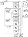
図4は、本発明の一実施形態に係る不吐出補完処理を示すフローチャートである。 FIG. 4 is a flowchart showing non-ejection complement processing according to an embodiment of the present invention.
記録データ生成部207によって、それそれぞれのインク色について、所定量のノズル列ごとの吐出データが生成されると、ステップS101で、補完処理グループ選択部209は、補完処理グループを選択する。具体的には、記録ヘッドにおけるノズルの吐出制約に基づいて予め定められた、隣接画素の連続吐出禁止数に従い、補完処理グループが選択される。例えば、ある方向において禁止の対象となる隣接画素が2つの場合、つまり、補完対象ノズルから見たとき1つの隣接画素に吐出されることを禁止する場合、16個のノズルに対応する画素を2つのグループに分け、それぞれが選択される。
When the recording data generation unit 207 generates a predetermined amount of ejection data for each nozzle row for each ink color, the complementary processing
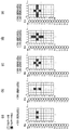
図5(a)〜(e)は、本実施形態に係る記録ヘッドの連続吐出を禁止する吐出制約の形態を説明する図である。これらの図において、図1に示したシートの搬送方向をX、記録ヘッドにおける各ノズル列のノズル配列方向をYとするとき、各画素は(Xm、Yn)(m、nは、0、1、2、・・・)と表される。すなわち、これらの図は、吐出データを、それぞれを記録するノズルに対応させて示している。なお、これらの図は、1つのノズル列(列0)について示すものであるが、他のノズル列についても同様であることはもちろんである。ここで、X方向はY方向に対して直交する直交方向である。 FIGS. 5A to 5E are views for explaining a form of ejection restriction that prohibits continuous ejection of the recording head according to the present embodiment. In these drawings, when the sheet conveyance direction shown in FIG. 1 is X and the nozzle arrangement direction of each nozzle row in the recording head is Y, each pixel is (Xm, Yn) (m, n are 0, 1 2, ...). That is, these drawings show the ejection data corresponding to the nozzles that record each. These drawings show one nozzle row (row 0), but it goes without saying that the same applies to the other nozzle rows. Here, the X direction is an orthogonal direction orthogonal to the Y direction.
図5(a)は、X方向に1つの画素分連続で吐出することを禁止する吐出制約を示している。この場合、同図に示すように、処理対象画素(X2,Y3)に対して、画素(X1,Y3)と画素(X3,Y3)の両方について吐出データが存在しないように、吐出データを生成する。補完処理でも同様、上記吐出制約によって補完候補となる画素(ないしノズル)が制約される。この図5(a)に示すX方向の吐出制約は、1つのノズルが連続して吐出する場合の吐出周波数の制約に由来するものである。 FIG. 5A shows the discharge restriction that prohibits continuous discharge for one pixel in the X direction. In this case, as shown in the figure, for the processing target pixel (X2, Y3), the ejection data is generated so that there is no ejection data for both the pixel (X1, Y3) and the pixel (X3, Y3). To do. Similarly, in the complementing process, pixels (or nozzles) that are candidates for complementation are restricted by the discharge restriction. The discharge restriction in the X direction shown in FIG. 5A is derived from the restriction on the discharge frequency when one nozzle discharges continuously.
図5(b)は、Y方向に1つの画素分連続で吐出することを禁止する吐出制約を示している。この場合、同図に示すように、処理対象画素(X2,Y3)に対して、画素(X2,Y2)と画素(X2,Y4)に吐出データが存在しないように、吐出データを生成する。補完処理でも同様、上記吐出制約によって補完候補となる画素(ないしノズル)が制約される。このY方向の吐出制約は、上述したように、ノズル間のクロストークを防ぐことができるものである。 FIG. 5B shows a discharge restriction that prohibits continuous discharge for one pixel in the Y direction. In this case, as shown in the figure, ejection data is generated for the processing target pixel (X2, Y3) so that there is no ejection data in the pixel (X2, Y2) and the pixel (X2, Y4). Similarly, in the complementing process, pixels (or nozzles) that are candidates for complementation are restricted by the discharge restriction. This discharge restriction in the Y direction can prevent crosstalk between nozzles as described above.
図5(c)は、X方向、Y方向共に1つの画素分連続で吐出することを禁止する吐出制約、図5(d)は、X方向に1つY方向に2つの画素分連続して吐出することを禁止する吐出制約をそれぞれ示している。さらに、図5(e)は、X方向に2つY方向に1つの画素分連続して吐出することを禁止する吐出制約をそれぞれ示している。上述したように、X方向の吐出制約はノズルの吐出周波数に依存するため、吐出周波数が低いヘッドほど連続吐出を禁止する数が大きくなる。また、Y方向の吐出制約はノズル同士のクロストークの度合いに依存する。X方向、Y方向の吐出制約は、このように使用する記録ヘッドの特性によって条件が変わることから、後述される不吐出補完処理に対する吐出制約はこれらの図に示したものに限定されるものではない。 FIG. 5C is a discharge restriction that prohibits continuous discharge for one pixel in both the X direction and the Y direction, and FIG. 5D is a view showing two continuous pixels in the X direction and two pixels in the Y direction. Each of the discharge restrictions prohibiting the discharge is shown. Further, FIG. 5E shows discharge restrictions for prohibiting continuous discharge of two pixels in the X direction and one pixel in the Y direction. As described above, since the discharge restriction in the X direction depends on the discharge frequency of the nozzle, the number of prohibition of continuous discharge becomes larger as the head has a lower discharge frequency. Further, the discharge restriction in the Y direction depends on the degree of crosstalk between the nozzles. Since the discharge restrictions in the X direction and the Y direction vary depending on the characteristics of the recording head used in this way, the discharge restrictions for the non-discharge supplement processing described later are not limited to those shown in these drawings. Absent.
再び図4を参照すると、次に、ステップS102で、記録データ保持部210は、ステップS101で選択された、補完処理グループ(の画素)とその隣接画素の吐出データを、記録データ生成部から受け取り保持する(S102)。
Referring to FIG. 4 again, next, in step S102, the recording
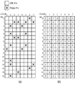
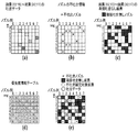
図6(a)および(b)は、本発明の一実施形態に係る選択される補完処理グループの二例を説明する図であり、ノズル列に対応した画素のデータとして示している。これらの図において、一つ目の補完処理グループ(以下、「第1グループ」)は、画素(X、Y)について、Y=0、2、4、6の画素からなるグループである。また、二つ目の補完処理グループ(以下、「第2グループ」)は、画素(X、Y)について、Y=1、3、5、7の画素からなるグループである。また、図6(a)および(b)に示す例では、ステップS101で選択される、2つに分けられた補完処理グループとして、一つ目の補完処理グループ(以下、「第3グループ」)が、画素(X、Y)について、Y=8、10、12、14の画素からなるグループとして示されている。また、二つ目の補完処理グループ(以下、「第3グループ」)が、画素(X、Y)について、Y=9、11、13、15の画素からなるグループである。すなわち、補完処理グループは、Y(ノズル配列)方向において1つおきの画素の組み合わせである。これのグループ分けは、図5(b)、(c)、(e)に示したY方において1つの連続した吐出を禁止する吐出制約に従ったものである。これら制約のうち、本実施形態の記録ヘッドは、図5(c)に示す吐出制約に従ったものであり、以下の説明もこの吐出制約に従った補完処理の例を説明する。一方、X方向については、それぞれの補完処理グループは、X=0〜7の画素を含む。なお、これらのグループのサイズ(X、Y方向それぞれの画素数)は、図12(d)にて後述される優先度テーブルのサイズに従ったものである。ステップS102のデータ取得では、上記2つの補完処理グループのうちの1つの補完処理グループの吐出データと、それらにY方向について隣接する画素の吐出データを取得する。例えば、補完処理グループが第1グループの場合、隣接する画素はY=1、3、5、7で示される画素(X=0〜7)である。これにより、取得される第1〜第4グループとそれらのY方向について隣接する画素の吐出データは、図10にて後述されるようなものである。 FIGS. 6A and 6B are diagrams for explaining two examples of selected complementary processing groups according to an embodiment of the present invention, and are shown as pixel data corresponding to nozzle rows. In these drawings, the first complementary processing group (hereinafter referred to as “first group”) is a group composed of pixels of Y = 0, 2, 4, and 6 for the pixel (X, Y). The second complementary processing group (hereinafter, “second group”) is a group composed of pixels Y = 1, 3, 5, and 7 for the pixel (X, Y). In the example shown in FIGS. 6A and 6B, the first complementary processing group (hereinafter, “third group”) is selected as the two complementary processing groups selected in step S101. Are shown as a group of pixels of Y = 8, 10, 12, 14 for pixel (X, Y). The second complementary processing group (hereinafter referred to as “third group”) is a group including pixels of Y = 9, 11, 13, and 15 with respect to the pixel (X, Y). That is, the complementary processing group is a combination of every other pixel in the Y (nozzle arrangement) direction. This grouping is in accordance with the discharge restriction that prohibits one continuous discharge in the Y direction shown in FIGS. 5B, 5C, and 5E. Among these constraints, the print head according to the present embodiment complies with the ejection constraints shown in FIG. 5C, and the following description will also explain an example of a complementary process according to the ejection constraints. On the other hand, for the X direction, each complementary processing group includes pixels of X = 0 to 7. Note that the sizes of these groups (the numbers of pixels in the X and Y directions) are in accordance with the size of the priority table described later with reference to FIG. In the data acquisition in step S102, the ejection data of one complementary processing group of the two complementary processing groups and the ejection data of the pixels adjacent to them in the Y direction are acquired. For example, when the complementary processing group is the first group, adjacent pixels are pixels indicated by Y = 1, 3, 5, and 7 (X = 0 to 7). Thereby, the acquired ejection data of the pixels adjacent to the first to fourth groups in the Y direction are as described later with reference to FIG.
図6(a)および(b)は、画素配列に関して補完処理の順序を示している。詳しくは、Yの値が同じ画素については、同図に示すように、並列処理によって補完処理が行われ、かつ、それぞれの並列処理では、Xの値に従った順序で補完処理が行われる。図6(a)に示す例では、補完処理の第1〜第4グループについて、Step0で、第1グループにおけるX0(X=0のこと、以下、同様)のY0(Y=0のこと、以下、同様)、Y2、Y4、Y6の4つの画素の補完処理を同時に行う。そして、その処理結果を参照してStep1で、第2グループにおける、X0のY1、Y3、Y5、Y7の4つの画素の補完処理を同時に行う。さらに、Step2で、第3グループにおけるX0のY8、Y10、Y12、Y14の4つの画素の補完処理を同時に行う。そして、その処理結果を参照してStep3で、第4グループにおける、X0のY9、Y11、Y13、Y15の4つの画素の補完処理を同時に行う。Step3の処理でY方向における1画素ライン分処理が終了すると、次に、X1のラインの処理を行い、以降同様に処理を行う。
FIGS. 6A and 6B show the order of the complement processing for the pixel arrangement. Specifically, as shown in the figure, complementary processing is performed by parallel processing for pixels having the same Y value, and in each parallel processing, complementary processing is performed in the order according to the X value. In the example shown in FIG. 6A, with respect to the first to fourth groups of the complement processing, at
図6(b)に示す例では、補完処理の第1〜第4グループについて、Step0で、第1グループにおけるX0のY0、Y2、Y4、Y6の4つの画素の補完処理を同時に行う。そして、その処理結果を参照してStep1で、第3グループにおける、X0のY8、Y10、Y12、Y14の4つの画素の補完処理を同時に行う。さらに、Step2で、第2グループにおけるX0のY1、Y3、Y5、Y7の4つの画素の補完処理を同時に行う。そして、その処理結果を参照してStep3で、第4グループにおける、X0のY9、Y11、Y13、Y15の4つの画素の補完処理を同時に行う。
In the example illustrated in FIG. 6B, with respect to the first to fourth groups of the complementing process, the complementing process of four pixels of Y0, Y2, Y4, and Y6 of X0 in the first group is simultaneously performed at Step0. Then, referring to the processing result, in
再び図4を参照すると、ステップS103以降では、図6(a)または図6(b)で上述した、Y方向における並列処理とX方向における順序で画素ごとの補完処理が行われる。すなわち、次のステップS103では、不吐情報読み出し部211は、上述した補完処理グループおよびその隣接画素に対応するノズルの不吐情報を不吐情報バッファ205から読み出し保持する(S103)。図7(a)は、不吐出情報を示す図であり、8つのノズル列0〜7のそれぞれにおけるノズルごと(seg0〜15)に不吐出情報を示している。例えば、ノズル列0のseg8のノズルが不吐出であることを示している。この情報は、X0〜X7とY0〜Y15の組で示される画素に対応させて保持されている。
Referring to FIG. 4 again, after step S103, the parallel processing in the Y direction and the complement processing for each pixel are performed in the order in the X direction described above with reference to FIG. 6A or 6B. That is, in the next step S103, the discharge failure
次にステップS104で、上記保持した不吐出情報に基づいて、処理対象となる画素を記録するノズルが不吐出ノズルで補完の対象となるノズルか否かを判断する。ステップS104で補完対象ノズルであると判断した場合は、ステップS105で、補完先候補選択部212は、次の条件を満たす補完候補画素を選択する。すなわち、補完対象ノズルとYの値が同じ(Xの値が異なる)他の画素が、それを記録するノズルが吐出不良でなく、吐出データが存在せず、かつ、その画素にY方向において隣接する画素に吐出データが存在しない、という条件を満たす補完候補画素を選択する。補完候補画素がある場合は、ステップS106で、補完処理部215は、その補完候補画素に吐出データを移動する。すなわち、補完候補画素に吐出データを配するとともに元の画素の吐出データを消去する。補完候補画素が複数ある場合は、補完優先度決定部213が優先度情報保持部214から優先度情報を読み出し、補完処理部215に知らせる。補完処理部215は、優先度情報に従い、1つの補完候補画素を定め、その画素に吐出データを移動する。ステップS107では、補完処理グループにおけるっ総ての画素について補完処理が終了したか否かを判断し、終了していない場合は、ステップS104以降の処理を繰り返す。図7(b)は、優先度情報を示す図であり、8つのノズル列0〜7のそれぞれにおけるノズルごと(seg0〜15)に優先度情報を示している。同図に示す例では、ノズル列0〜7に対してseg0〜7とseg8〜15がそれぞれ1単位であり、相互に同じ優先度情報となっている。なお、この優先度情報は、図7(b)に示す形態に限られないことはもちろんである。
Next, in step S104, based on the held non-ejection information, it is determined whether or not the nozzle that records the pixel to be processed is a non-ejection nozzle and a nozzle to be complemented. If it is determined in step S104 that the nozzle is a complement target nozzle, in step S105, the complement destination
ステップS105で、条件に合う補完候補画素が無いと判断した場合は、ステップS109でCPUにその旨(警告)を通知する。ステップS107でグループ内の総ての画素について補完処理が終了したと判断した場合は、ステップS108で、上述した4つの補完処理グループの処理が終了したか否かを判断する。総てについて終了していない場合は、Y0〜Y15で、X8以降の他の画素列について、上記と同様、ステップS101で4つの補完処理グループを選択して、同様の処理を行う。そして、総ての補完処理グループについて補完処理が終了すると、ステップS109で、処理結果の吐出データを記録バッファ206に書き込む。
If it is determined in step S105 that there is no complementary candidate pixel that meets the conditions, the CPU notifies the CPU (warning) in step S109. If it is determined in step S107 that the complement processing has been completed for all the pixels in the group, it is determined in step S108 whether the above-described processing of the four complement processing groups has been completed. If all the processing has not been completed, Y4 to Y15, and for the other pixel columns after X8, the same processing is performed by selecting four complementary processing groups in step S101 as described above. When the complementing process is completed for all the complementing process groups, the process result ejection data is written in the
以上説明した、図5(c)に示したX、Y方向にそれぞれ1つ分の連続吐出が禁止された場合の不吐出補完処理を、具体的な吐出データ等の配置とともに以下に説明する。 The non-discharge complementing process when one continuous discharge in the X and Y directions shown in FIG. 5C described above is prohibited will be described below together with specific arrangement of discharge data and the like.
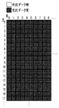
記録データ生成部207で生成される記録データが、一例として、図8に示すように、総ての画素に1つのドットが形成される吐出データであるとする。この吐出データは、8つの吐出列のいずれかに振り分けて記録される。図9は、吐出データを8つのノズル列のどの吐出列(のノズル)に振り分けるためのマスクデータを示す図である。同図に示すように、本実施形態のマスクデータは、Y方向はノズル列の16個のノズルseg0〜15に対応し、X方向は8つのノズル列に対応したサイズを1つの単位としている。本実施形態では、後述されるように、この1単位の所定領域の記録データに対して不吐出補完処理を行う。また、マスクデータは、8つのノズル列0〜7に均等に振り分けるものである。
As an example, it is assumed that the print data generated by the print data generation unit 207 is ejection data in which one dot is formed in all pixels as shown in FIG. This discharge data is distributed and recorded in one of the eight discharge rows. FIG. 9 is a diagram showing mask data for distributing the discharge data to any of the eight nozzle arrays. As shown in the figure, in the mask data of this embodiment, the Y direction corresponds to 16 nozzles seg 0 to 15 in the nozzle row, and the X direction has a size corresponding to eight nozzle rows as one unit. In the present embodiment, as will be described later, the non-ejection complementing process is performed on the recording data of the predetermined area of one unit. The mask data is equally distributed to the eight
図10は、図8に示すベタ画像の吐出データに対して、図9のマスクデータを用いて記録に用いるノズル列を振り分けた結果をノズル列ごとに示す図である。例えば、ノズル列0は、画素(2、0)、画素(5、1)、画素(3、2)、・・・、画素(6、14)、画素(0、15)の吐出データ(吐出“1”を示すデータ)に振り分けられる。そして、図10から明らかなように、マスクデータによるノズル列の振り分けは、いずれのノズル列でも隣接する画素に吐出データ(吐出“1”を示すデータ)が配置されないようにしている。
FIG. 10 is a diagram showing, for each nozzle row, the result of assigning the nozzle rows used for printing using the mask data of FIG. 9 to the discharge data of the solid image shown in FIG. For example, the
図11は、図10のようにノズル列が振り分けられた吐出データについて、図5(c)に示したX、Y方向それぞれに1つの画素分隣接する画素に吐出データが無い画素を説明する図である。すなわち、図4にて上述した画素ごとの補完処理でその対象ノズルについて隣接する画素があるか否かを判断するときに参照される(S105)データを示している。図11は、一例として、8つのノズル列0〜7の吐出データそれぞれについて、X2、Y0〜Y7の画素それぞれに対してX、Y方向に1画素分隣接する画素に吐出データが存在しない画素を示している。例えば、ノズル列0の吐出データでは、X2、Y4、Y5、Y7の画素が、X、Y方向に1画素分隣接する画素に吐出データが存在しないことを示している。
FIG. 11 is a diagram for explaining pixels having no discharge data in pixels adjacent to one pixel in each of the X and Y directions shown in FIG. 5C with respect to the discharge data in which the nozzle rows are distributed as shown in FIG. It is. That is, FIG. 4 shows data that is referred to when it is determined whether or not there is an adjacent pixel for the target nozzle in the complementing process for each pixel described above (S105). FIG. 11 shows, as an example, pixels for which discharge data does not exist in pixels adjacent to the X2 and Y0 to Y7 pixels by one pixel for each of the discharge data of the eight
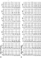
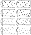
図12(a)〜(e)は、図10に示すノズル列が振り分けられた吐出データに対して、図11で説明した隣接画素の吐出データの有無に基づいて行われる不吐出補完処理を説明する図である。図12(a)〜(e)は、図10に示す吐出データのうち、画素(X2,Y0)〜画素(X2,Y7)の8画素を1つの単位とし、Y方向に処理して行くものとして説明する。 12A to 12E illustrate the non-ejection complementing process that is performed based on the presence / absence of the ejection data of the adjacent pixels described in FIG. 11 with respect to the ejection data to which the nozzle rows illustrated in FIG. 10 are allocated. It is a figure to do. 12 (a) to 12 (e), the discharge data shown in FIG. 10 is processed in the Y direction with eight pixels from pixel (X2, Y0) to pixel (X2, Y7) as one unit. Will be described.
図12(a)は、上記8画素を8つのノズル列のうちのどのノズル列(のノズル)で記録するかを示している。図12(b)は、各ノズル列のノズルの不吐出情報を示している。さらに、図12(c)は、図12(a)に示す吐出データについて、X、Y方向に1つ分隣接する画素に吐出データが存在しない画素を示しており、図11に示す隣接する画素に吐出データが存在しない画素をノズル列ごとに抽出したものである。図12(d)は、優先度情報テーブルを示しており、補完候補画素が複数ある場合は、この優先度に従って優先度の高い順に補完候補画素を選択する。 FIG. 12A shows in which nozzle row (nozzle) of the eight nozzle rows the eight pixels are recorded. FIG. 12B shows the non-ejection information of the nozzles in each nozzle row. Further, FIG. 12C shows a pixel in which there is no discharge data in the pixel adjacent to the discharge data shown in FIG. 12A by one in the X and Y directions, and the adjacent pixel shown in FIG. Pixels for which no ejection data exists are extracted for each nozzle row. FIG. 12D shows a priority information table. When there are a plurality of complement candidate pixels, complement candidate pixels are selected in descending order of priority according to this priority.
補完候補画素の条件として、その画素に対応するノズルが不吐出ノズルでないこと、その画素に吐出データが存在していないこと、隣接画素に吐出データが存在しないこと、であり、これらの総ての条件を満たす画素が補完候補画素として設定される。 The conditions for the complementary candidate pixel are that the nozzle corresponding to that pixel is not a non-ejection nozzle, that there is no ejection data in that pixel, and that there is no ejection data in an adjacent pixel. Pixels that satisfy the condition are set as complementary candidate pixels.
図12(e)は、図12(a)〜(c)に示すデータを重ね合わせて得られるデータを示している。図12(e)において、例えば、ノズル列2のseg1のノズルは不吐出(図12(b))であり、従って、このノズルに対応するY1の画素に吐出データある場合、その画素は不吐出補完対象画素となる。この不吐出補完対象画素の吐出データは、上述した不吐出補完処理によって、隣接する画素に吐出データが無い画素(図12(e)においてグレーで示される、Y2で、ノズル列5または6の画素)のいずれかに移される。そして、この例のように、補完候補画素が複数ある場合は、図12(d)に示す優先度情報テーブルを参照し、優先度の高い順に補完候補画素を選択する。
FIG.12 (e) has shown the data obtained by superimposing the data shown to Fig.12 (a)-(c). In FIG. 12E, for example, the nozzle of seg1 in the
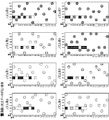
図13(a)〜(c)は、本実施形態に係る吐出データの移動を伴う補完処理の詳細を説明する図であり、図13(c)が本実施形態の処理、図13(a)および(b)が比較例の処理、をそれぞれ示している。 FIGS. 13A to 13C are diagrams for explaining the details of the complementary process involving the movement of the ejection data according to the present embodiment. FIG. 13C is the process of the present embodiment, and FIG. And (b) has each shown the process of the comparative example.
図13(a)は、Y0〜Y7の画素列について不吐出補完処理を並列に行った場合を示している。この処理では、ノズル列2のY1の画素の吐出データがノズル列5のY1の画素に移動し、また、この画素が隣接することを考慮しないため、ノズル列4のY2の画素の吐出データがノズル列5のY2の画素に移動し、Y方向に隣接するデータが生成される。その結果、隣接ノズル間の連続吐出を避けることができない。
FIG. 13A shows a case where non-ejection complement processing is performed in parallel for the pixel columns Y0 to Y7. In this process, the discharge data of the Y1 pixel in the
図13(b)は、Y0〜Y7の画素列について不吐出補完処理を、Y0〜Y7にかけて1画素ずつ順次行った場合を示している。Y1の画素の不吐出補完処理によって、ノズル列2のY1の画素の吐出データがノズル列5のY1の画素に移動する。次に行われるY2の画素の不吐出補完処理では、優先度に従いノズル列5のY2の画素の吐出データを移動させるようとするが、これに隣接するノズル列5のY1の画素に、Y1の画素の不吐出補完処理による吐出データがあることから、この画素には移動しない。代わりに、ノズル列6のY2の画素の吐出データを移動させる。このような順次の処理は、隣接する画素に吐出データが生成されないが、処理時間が長くなる。
FIG. 13B shows a case where the non-ejection complement processing is sequentially performed pixel by pixel from Y0 to Y7 for the pixel rows Y0 to Y7. The ejection data of the Y1 pixel of the
図13(c)は、本実施形態に係る不吐出補完処理を示しており、上述したように、Y0、Y2、Y4、Y6のグループ0と、Y1、Y3、Y5、Y7のグループ1とに分けて、それぞれのグループ内のYk(k=0、2、4、6またはk=1、3、5、7)の画素に対する処理は並列に行う。具体的には、図6(a)にて上述したように、先ず、グループ0に属するY0、Y2、Y4、Y6の画素の不吐出補完処理が並列に行われる。この処理では、例えば、ノズル列4のY2の不吐出補完画素の吐出データは、ノズル列5のY2の画素に移動する。このようなグループ0のYkの画素の並列の補完処理が終わると、次に、グループ1のYkの画素の並列の補完処理が行われる。この処理では、既に行われているグループ0の補完処理結果を考慮することから、例えば、ノズル列2のY1の不吐出補完画素の吐出データは、補完処理によるY2の吐出データが隣接するノズル列5のY1の画素でなく、ノズル列6のY1の画素に移動する。
FIG. 13C shows the non-ejection complement processing according to the present embodiment. As described above, the
以上のように、本実施形態の不吐出補完処理によれば、隣接画素に吐出データが存在しないようにしつつ、図13(b)に示す順次の処理の時間の1/4の時間で処理を行うことが可能となる。 As described above, according to the non-ejection complementing process of the present embodiment, the process is performed in ¼ time of the sequential process shown in FIG. 13B while no ejection data exists in adjacent pixels. Can be done.
なお、後に処理するグループの補完候補画素は、先に処理するグループの不吐出補完処理に比べて少なくなった状態となる。このような補完候補画素の偏りは、吐出データの吐出量や記録ヘッドのノズル列数の条件によって問題になる場合と、ならない場合がある。この偏りを平均化する必要がある場合は、例えば、1ページの記録毎、複数ページの記録毎、記録装置に投入された1つの記録ジョブ毎、一日毎など一定時間毎など、処理するグループ単位での処理順を変更することにより補完先候補の偏りを平均化することができる。 It should be noted that the number of complement candidate pixels for the group to be processed later is smaller than that of the non-ejection complement process for the group to be processed first. Such a bias of candidate pixels for complementation may or may not be a problem depending on the condition of the ejection amount of ejection data and the number of nozzle rows of the recording head. When this deviation needs to be averaged, for example, for each group of pages to be processed, for example, for each recording of one page, for each recording of a plurality of pages, for each recording job input to the recording apparatus, or for every fixed time such as every day By changing the processing order in, the bias of the candidate for complementation can be averaged.
図5(d)に示すように、Y方向において2つの画素に連続して吐出データが存在するのを禁止する吐出制約の場合は、図14に示すように、2画素おきの画素ごとに処理グループを形成する。この場合、3組の処理グループとなる。この場合も、2つのグループの場合と同様、それぞれのグループ内の複数の画素について並列処理を行い、また、グループ間では隣接画素に吐出データが存在しないようにする。一般化すると、N個の画素に連続して吐出データが存在するのを禁止する吐出制約の場合は、N画素おき(所定数おき)の画素からなる処理グループを形成し、それぞれのグループで複数の画素について並列処理を行う。 As shown in FIG. 5D, in the case of the discharge restriction that prohibits the continuous existence of discharge data in two pixels in the Y direction, processing is performed for every second pixel as shown in FIG. Form a group. In this case, there are three processing groups. In this case as well, as in the case of two groups, parallel processing is performed for a plurality of pixels in each group, and ejection data does not exist in adjacent pixels between groups. Generally speaking, in the case of ejection restriction that prohibits the ejection data from being continuously present in N pixels, a processing group composed of pixels every N pixels (every predetermined number) is formed, and a plurality of groups are formed in each group. Parallel processing is performed on the pixels.
なお、以上の説明はY方向に処理する例に関するものであるが、不吐出補完処理をX方向において処理する場合も同様の処理を行うことが可能であることは、以上の説明からも明らかである。 Although the above description relates to an example of processing in the Y direction, it is apparent from the above description that the same processing can be performed when the non-ejection complement processing is processed in the X direction. is there.
(他の実施形態)
以上の実施形態は、フルラインタ方式の記録ヘッドを用いる場合に関するものであるが、本発明は、シリアル方式の記録ヘッドを用い、走査方向の画素を複数回の走査で異なるノズルで記録するマルチパス記録を行う形態にも適用することができる。例えば、図10において、ノズル列0〜7の記録データは、1つのノズル列による8回の走査0〜7それぞれで記録するデータとすることができる。この8パスのマルチパス記録の吐出データに対して、上述した不吐出補完処理を行うことにより、他の走査で対応する記録可能なノズルによって補完をすることができる。
(Other embodiments)
The above embodiment relates to the case of using a full line type recording head, but the present invention uses a serial type recording head and performs multi-pass recording in which pixels in the scanning direction are recorded by different nozzles in a plurality of scans. It is applicable also to the form which performs. For example, in FIG. 10, the print data of the
また、上述した不吐出補完処理は、図3に示したようにインクジェット記録装置における制御部が行うものであるが、吐出データの生成を初め、パーソナルコンピュータなどのホスト装置において不吐出補完処理を行ってもよい。この不吐出補完処理を行う装置を、ホスト装置や上記インクジェット記録装置を含め「画像処理装置」と言う。 Further, the non-ejection complementing process described above is performed by the control unit in the ink jet recording apparatus as shown in FIG. 3. May be. An apparatus that performs this non-ejection complementing process is referred to as an “image processing apparatus” including the host apparatus and the inkjet recording apparatus.
105 記録ヘッド
110 記録制御部
208 不吐出補完処理部
209 補完処理グループ選択部
210 記録データ保持部
211 不吐出情報読み出し部
212 補完候補画素選択部
213 補完優先度決定部
215 補完処理部
DESCRIPTION OF
Claims (8)
前記所定領域の記録データにおいて、前記ノズルの配列方向または該配列方向と直交する直交方向の画素列のそれぞれの画素について、当該画素を記録するノズルが不吐出である場合は、当該画素を記録可能な他のノズルで記録するよう、補完処理を行う補完手段、を具え、
前記補完手段は、前記配列方向または前記直交方向における前記画素列を、当該画素列の所定数おきの画素からなる処理グループに分け、複数の前記処理グループについて順次に補完処理を行うとともに、それぞれの前記処理グループにおける画素に対する補完処理を並列処理として行うことを特徴とする画像処理装置。 An image processing apparatus for generating recording data for recording a predetermined area of a recording medium by a nozzle array in which a plurality of nozzles each ejecting ink are arranged,
In the recording data of the predetermined area, if the nozzle that records the pixel is non-ejection for each pixel in the pixel arrangement direction of the nozzle or the orthogonal direction orthogonal to the arrangement direction, the pixel can be recorded In order to record with other nozzles, the supplement means for performing the complement processing,
The complementing unit divides the pixel columns in the arrangement direction or the orthogonal direction into processing groups each including a predetermined number of pixels of the pixel column, sequentially performs a complementary process on the plurality of processing groups, An image processing apparatus, wherein complementary processing for pixels in the processing group is performed as parallel processing.
前記所定領域の記録データにおいて、前記ノズルの配列方向または該配列方向と直交する直交方向の画素列のそれぞれの画素について、当該画素を記録するノズルが不吐出である場合は、当該画素を記録可能な他のノズルで記録するよう、補完処理を行う補完手段、を具え、
前記補完手段は、前記配列方向または前記直交方向における前記画素列を、当該画素列のN個おきの画素からなる処理グループに分け、複数の前記処理グループについて順次に補完処理を行うとともに、それぞれの前記処理グループにおける画素に対する補完処理を並列処理として行うことを特徴とする画像処理装置。 An image processing apparatus for generating recording data for recording a predetermined area of a recording medium by a nozzle array in which a plurality of nozzles each ejecting ink are arranged,
In the recording data of the predetermined area, if the nozzle that records the pixel is non-ejection for each pixel in the pixel arrangement direction of the nozzle or the orthogonal direction orthogonal to the arrangement direction, the pixel can be recorded In order to record with other nozzles, the supplement means for performing the complement processing,
The complementing unit divides the pixel columns in the arrangement direction or the orthogonal direction into processing groups composed of every N pixels of the pixel column, and sequentially performs a complementing process on the plurality of processing groups. An image processing apparatus, wherein complementary processing for pixels in the processing group is performed as parallel processing.
前記所定領域の記録データにおいて、前記ノズルの配列方向または該配列方向と直交する直交方向の画素列のそれぞれの画素について、当該画素を記録するノズルが不吐出である場合は、当該画素を記録可能な他のノズルで記録するよう、補完処理を行う補完工程、を有し、
前記補完工程では、前記配列方向または前記直交方向における前記画素列を、当該画素列の所定数おきの画素からなる処理グループに分け、複数の前記処理グループについて順次に補完処理を行うとともに、それぞれの前記処理グループにおける画素に対する補完処理を並列処理として行うことを特徴とする記録データ生成方法。 A recording data generation method for generating recording data for recording a predetermined area of a recording medium by a nozzle row in which a plurality of nozzles each ejecting ink are arranged,
In the recording data of the predetermined area, if the nozzle that records the pixel is non-ejection for each pixel in the pixel arrangement direction of the nozzle or the orthogonal direction orthogonal to the arrangement direction, the pixel can be recorded A supplementary process for performing supplementary processing so as to record with other nozzles,
In the complementing step, the pixel columns in the arrangement direction or the orthogonal direction are divided into processing groups each including a predetermined number of pixels of the pixel column, and a plurality of the processing groups are sequentially supplemented. A recording data generation method, wherein complement processing for pixels in the processing group is performed as parallel processing.
Priority Applications (2)
| Application Number | Priority Date | Filing Date | Title |
|---|---|---|---|
| JP2016156868A JP6862124B2 (en) | 2016-08-09 | 2016-08-09 | Image processing device and image processing method |
| US15/669,632 US10286650B2 (en) | 2016-08-09 | 2017-08-04 | Image processing apparatus and image processing method |
Applications Claiming Priority (1)
| Application Number | Priority Date | Filing Date | Title |
|---|---|---|---|
| JP2016156868A JP6862124B2 (en) | 2016-08-09 | 2016-08-09 | Image processing device and image processing method |
Publications (3)
| Publication Number | Publication Date |
|---|---|
| JP2018024152A true JP2018024152A (en) | 2018-02-15 |
| JP2018024152A5 JP2018024152A5 (en) | 2019-09-26 |
| JP6862124B2 JP6862124B2 (en) | 2021-04-21 |
Family
ID=61160086
Family Applications (1)
| Application Number | Title | Priority Date | Filing Date |
|---|---|---|---|
| JP2016156868A Active JP6862124B2 (en) | 2016-08-09 | 2016-08-09 | Image processing device and image processing method |
Country Status (2)
| Country | Link |
|---|---|
| US (1) | US10286650B2 (en) |
| JP (1) | JP6862124B2 (en) |
Cited By (1)
| Publication number | Priority date | Publication date | Assignee | Title |
|---|---|---|---|---|
| WO2023054360A1 (en) * | 2021-09-28 | 2023-04-06 | 京セラドキュメントソリューションズ株式会社 | Image formation device |
Citations (9)
| Publication number | Priority date | Publication date | Assignee | Title |
|---|---|---|---|---|
| JPH106488A (en) * | 1996-06-24 | 1998-01-13 | Canon Inc | Ink jet recording method and apparatus |
| US6273542B1 (en) * | 1998-12-22 | 2001-08-14 | Eastman Kodak Company | Method of compensating for malperforming nozzles in an inkjet printer |
| US20020060707A1 (en) * | 2000-02-15 | 2002-05-23 | Chia-Lei Yu | Ink jet printer with a compensation function for malfunctioning nozzles |
| JP2005225036A (en) * | 2004-02-12 | 2005-08-25 | Sony Corp | Discharge control device, ink discharge device, discharge control method, screen display method, program, and recording medium |
| JP2009000997A (en) * | 2007-05-24 | 2009-01-08 | Dainippon Screen Mfg Co Ltd | Image data generating method, printing method, image data generating apparatus, and printer |
| JP2009012335A (en) * | 2007-07-05 | 2009-01-22 | Seiko Epson Corp | Ink ejection device |
| JP2011152710A (en) * | 2010-01-27 | 2011-08-11 | Fujifilm Corp | Image forming apparatus and method |
| JP2013032027A (en) * | 2012-11-21 | 2013-02-14 | Canon Inc | Recording apparatus |
| JP2014240172A (en) * | 2013-06-12 | 2014-12-25 | キヤノン株式会社 | Ink jet recording device and inkjet recording method |
Family Cites Families (3)
| Publication number | Priority date | Publication date | Assignee | Title |
|---|---|---|---|---|
| JP4164305B2 (en) * | 2002-07-24 | 2008-10-15 | キヤノン株式会社 | Inkjet recording method and inkjet recording apparatus |
| JP4262165B2 (en) | 2003-09-03 | 2009-05-13 | キヤノン株式会社 | Recording apparatus and data processing method |
| JP5473704B2 (en) * | 2010-03-24 | 2014-04-16 | 富士フイルム株式会社 | Test pattern printing method and inkjet recording apparatus |
-
2016
- 2016-08-09 JP JP2016156868A patent/JP6862124B2/en active Active
-
2017
- 2017-08-04 US US15/669,632 patent/US10286650B2/en active Active
Patent Citations (9)
| Publication number | Priority date | Publication date | Assignee | Title |
|---|---|---|---|---|
| JPH106488A (en) * | 1996-06-24 | 1998-01-13 | Canon Inc | Ink jet recording method and apparatus |
| US6273542B1 (en) * | 1998-12-22 | 2001-08-14 | Eastman Kodak Company | Method of compensating for malperforming nozzles in an inkjet printer |
| US20020060707A1 (en) * | 2000-02-15 | 2002-05-23 | Chia-Lei Yu | Ink jet printer with a compensation function for malfunctioning nozzles |
| JP2005225036A (en) * | 2004-02-12 | 2005-08-25 | Sony Corp | Discharge control device, ink discharge device, discharge control method, screen display method, program, and recording medium |
| JP2009000997A (en) * | 2007-05-24 | 2009-01-08 | Dainippon Screen Mfg Co Ltd | Image data generating method, printing method, image data generating apparatus, and printer |
| JP2009012335A (en) * | 2007-07-05 | 2009-01-22 | Seiko Epson Corp | Ink ejection device |
| JP2011152710A (en) * | 2010-01-27 | 2011-08-11 | Fujifilm Corp | Image forming apparatus and method |
| JP2013032027A (en) * | 2012-11-21 | 2013-02-14 | Canon Inc | Recording apparatus |
| JP2014240172A (en) * | 2013-06-12 | 2014-12-25 | キヤノン株式会社 | Ink jet recording device and inkjet recording method |
Cited By (3)
| Publication number | Priority date | Publication date | Assignee | Title |
|---|---|---|---|---|
| WO2023054360A1 (en) * | 2021-09-28 | 2023-04-06 | 京セラドキュメントソリューションズ株式会社 | Image formation device |
| JPWO2023054360A1 (en) * | 2021-09-28 | 2023-04-06 | ||
| JP7737615B2 (en) | 2021-09-28 | 2025-09-11 | 京セラドキュメントソリューションズ株式会社 | Image forming device |
Also Published As
| Publication number | Publication date |
|---|---|
| US20180043682A1 (en) | 2018-02-15 |
| US10286650B2 (en) | 2019-05-14 |
| JP6862124B2 (en) | 2021-04-21 |
Similar Documents
| Publication | Publication Date | Title |
|---|---|---|
| CN107696712B (en) | Inkjet printing apparatus and inkjet printing method | |
| JP6095398B2 (en) | Recording apparatus and recording method | |
| US7740336B2 (en) | Array type multi-pass inkjet printer and operating method thereof | |
| JP6488803B2 (en) | Droplet ejection apparatus, mask pattern, and droplet ejection method | |
| JP5776348B2 (en) | Image forming apparatus and image forming method | |
| JP2014008660A (en) | Inkjet recorder, and method for generating mask pattern | |
| JP4343867B2 (en) | Inkjet recording device | |
| JP6054850B2 (en) | Recording apparatus and recording method | |
| JP2018024152A (en) | Image processing apparatus and recording data generation method | |
| JP2010076230A (en) | Liquid discharge apparatus | |
| JP2020121487A (en) | Recording apparatus and recording method | |
| JP2007144847A (en) | Inkjet printer | |
| EP1495874B1 (en) | Printing with non-uniform passes per raster | |
| JP2009000837A (en) | Liquid ejection apparatus and liquid ejection method | |
| JP2007276353A (en) | Ink jet recording apparatus, recording control method for ink jet recording apparatus, program, and storage medium | |
| JP5885606B2 (en) | Image forming apparatus | |
| JP2010082971A (en) | Liquid delivery device and delivery control method therefor | |
| US8967770B2 (en) | Inkjet printer and printing method | |
| JP7435331B2 (en) | Image recording device, image recording system, image recording method and program | |
| JP4274012B2 (en) | Recording device | |
| JP2011037037A (en) | Image recording apparatus and control method thereof | |
| US20110286013A1 (en) | Recording apparatus | |
| JP6087800B2 (en) | Recording apparatus and recording method | |
| JP2015024570A (en) | Recording apparatus and recording method | |
| JP2009001025A (en) | Liquid ejection apparatus and liquid ejection method |
Legal Events
| Date | Code | Title | Description |
|---|---|---|---|
| A521 | Request for written amendment filed |
Free format text: JAPANESE INTERMEDIATE CODE: A523 Effective date: 20190809 |
|
| A621 | Written request for application examination |
Free format text: JAPANESE INTERMEDIATE CODE: A621 Effective date: 20190809 |
|
| A977 | Report on retrieval |
Free format text: JAPANESE INTERMEDIATE CODE: A971007 Effective date: 20200624 |
|
| A131 | Notification of reasons for refusal |
Free format text: JAPANESE INTERMEDIATE CODE: A131 Effective date: 20200714 |
|
| A521 | Request for written amendment filed |
Free format text: JAPANESE INTERMEDIATE CODE: A523 Effective date: 20200907 |
|
| TRDD | Decision of grant or rejection written | ||
| A01 | Written decision to grant a patent or to grant a registration (utility model) |
Free format text: JAPANESE INTERMEDIATE CODE: A01 Effective date: 20210302 |
|
| A61 | First payment of annual fees (during grant procedure) |
Free format text: JAPANESE INTERMEDIATE CODE: A61 Effective date: 20210331 |
|
| R151 | Written notification of patent or utility model registration |
Ref document number: 6862124 Country of ref document: JP Free format text: JAPANESE INTERMEDIATE CODE: R151 |