JP2018024175A - Finish treatment machine for synthetic resin-made bottle - Google Patents
Finish treatment machine for synthetic resin-made bottle Download PDFInfo
- Publication number
- JP2018024175A JP2018024175A JP2016157651A JP2016157651A JP2018024175A JP 2018024175 A JP2018024175 A JP 2018024175A JP 2016157651 A JP2016157651 A JP 2016157651A JP 2016157651 A JP2016157651 A JP 2016157651A JP 2018024175 A JP2018024175 A JP 2018024175A
- Authority
- JP
- Japan
- Prior art keywords
- bottle
- finishing
- transfer mechanism
- synthetic resin
- stop position
- Prior art date
- Legal status (The legal status is an assumption and is not a legal conclusion. Google has not performed a legal analysis and makes no representation as to the accuracy of the status listed.)
- Granted
Links
- 238000011282 treatment Methods 0.000 title abstract 10
- 230000007246 mechanism Effects 0.000 claims description 29
- 238000007730 finishing process Methods 0.000 claims description 23
- 229920003002 synthetic resin Polymers 0.000 claims description 13
- 239000000057 synthetic resin Substances 0.000 claims description 13
- 238000007664 blowing Methods 0.000 claims description 8
- 239000002699 waste material Substances 0.000 claims description 6
- 238000000071 blow moulding Methods 0.000 abstract description 6
- 230000007723 transport mechanism Effects 0.000 abstract description 5
- 238000009434 installation Methods 0.000 abstract description 4
- 238000000465 moulding Methods 0.000 abstract description 2
- 230000002708 enhancing effect Effects 0.000 abstract 1
- 238000000034 method Methods 0.000 description 11
- 238000005516 engineering process Methods 0.000 description 2
- 230000002093 peripheral effect Effects 0.000 description 1
Images


Landscapes
- Blow-Moulding Or Thermoforming Of Plastics Or The Like (AREA)
Abstract
Description
本発明は、合成樹脂製ボトルの仕上げ処理機に関するものである。 The present invention relates to a finishing machine for synthetic resin bottles.
ブロー成形によって製造される合成樹脂製ボトルは、離型後の成形物に対して、バリ取り、余剰頭部の切断(ラフカット)、リーミング、チップブローなどの仕上げ処理を行って、製品ボトルを得ている。このような仕上げ処理を行う装置としては、コンベアによって整列状態でボトルを移送する過程で、ボトルを把持して底部のバリ取りと余剰頭部の切断を行う装置(下記特許文献1参照)や、回転式の切削刃を用いてボトル口部の内周面を仕上げ加工する装置(下記特許文献2参照)などが知られている。
Synthetic resin bottles manufactured by blow molding are finished products such as deburring, cutting of excess head (rough cut), reaming, chip blowing, etc., after the mold release to obtain product bottles. ing. As an apparatus for performing such a finishing process, in the process of transferring bottles in an aligned state by a conveyor, an apparatus that grips the bottles and deburrs the bottom and cuts the excess head (see Patent Document 1 below), An apparatus for finishing the inner peripheral surface of a bottle mouth using a rotary cutting blade (see
ブロー成形後のボトルに対する仕上げ処理は、前述したように、一般に複数の異なる処理が必要になる。このような仕上げ処理を全て自動で行う場合には、間欠的なボトル搬送装置の停止位置に、各処理ステーション(処理ユニット)を配備することがなされており、従来の仕上げ処理では、ボトル搬送装置として間欠ロータリ式のターレット搬送装置が用いられている。 As described above, a finishing process for a bottle after blow molding generally requires a plurality of different processes. When all such finishing processes are performed automatically, each processing station (processing unit) is arranged at a stop position of the intermittent bottle transporting apparatus. In the conventional finishing process, the bottle transporting apparatus is used. As an example, an intermittent rotary turret conveyance device is used.
ブロー成形後の仕上げ処理は、ボトルの製品仕様によって必要な処理が異なる場合があり、その際に、処理ステーション数の増加が必要な場合もある。そして、ボトル搬送装置として、間欠ロータリ式のターレット搬送を採用している従来技術では、ターレットに設けられるボトル保持部の数が決まっているので、処理ステーションの数を増加するためには、ターレットを含めた仕上げ処理機全体を設計変更せざるを得ず、多品種ボトルへの対応が困難な問題がある。また、処理ステーションの数の上限値に合わせてターレットにおけるボトル保持部の数を設定することは可能であるが、その場合には、ターレットのボトル保持部数を処理ステーション間の間隔を考慮して設けるため、ターレットを含めた仕上げ処理機の設置占有面積が大きくなってしまう問題がある。 The finishing process after blow molding may require different processes depending on the product specifications of the bottle, and in that case, it may be necessary to increase the number of processing stations. And, in the conventional technology that employs intermittent rotary turret conveyance as the bottle conveyance device, the number of bottle holders provided in the turret is determined, so in order to increase the number of processing stations, turrets are used. There is a problem that it is difficult to cope with a wide variety of bottles, because the design of the entire finishing machine including it must be changed. In addition, it is possible to set the number of bottle holders in the turret according to the upper limit value of the number of processing stations. In this case, the number of bottle holders in the turret is provided in consideration of the interval between the processing stations. Therefore, there is a problem that the installation occupation area of the finishing machine including the turret becomes large.
本発明は、このような事情に対処することを課題とするものである。すなわち、合成樹脂製ボトルの成形後の仕上げ処理を行う仕上げ処理機において、処理の変更や処理ステーションの増設を簡易に行うことができるようにすると共に、設置スペースの効率化を可能にすること、などが本発明の課題である。 This invention makes it a subject to cope with such a situation. That is, in the finishing machine that performs the finishing process after the molding of the synthetic resin bottle, it is possible to easily change the process and increase the number of processing stations and to make the installation space more efficient. These are the problems of the present invention.
このような課題を解決するために、本発明による合成樹脂製ボトルの仕上げ処理機は、以下の構成を具備するものである。
ブロー成形後のボトルに仕上げ処理を施す仕上げ処理機であって、口部を下にしたボトルを把持して設定間隔毎に間欠直線移動させるボトル移送機構と、前記ボトル移送機構のボトル停止位置に対応して配置され、各停止位置で前記ボトル移送機構に把持されたボトルに異なる仕上げ処理を行う複数の処理ユニットと、前記ボトル移送機構を支持すると共に、前記複数の処理ユニットを直線的に配列支持する支持枠とを備えること特徴とする合成樹脂製ボトルの仕上げ処理機。
In order to solve such problems, a synthetic resin bottle finishing machine according to the present invention has the following configuration.
A finishing machine that performs a finishing process on a bottle after blow molding, a bottle transfer mechanism that grips a bottle with its mouth down and moves it intermittently at set intervals, and a bottle stop position of the bottle transfer mechanism Correspondingly arranged, a plurality of processing units for performing different finishing processes on the bottles gripped by the bottle transfer mechanism at each stop position, and supporting the bottle transfer mechanism, and arranging the plurality of processing units linearly A synthetic resin bottle finishing machine comprising a supporting frame for supporting.
このような特徴を備えた合成樹脂製ボトルの仕上げ処理機によると、直線的に配列した処理ユニットを適宜変更・増設することで、他品種ボトルの様々な仕上げ処理に対応することができ、処理ユニットの直線的な配置によって、設置占有面積の省スペース化が可能になる。 According to the synthetic resin bottle finishing machine with such features, it is possible to handle various finishing processes for other types of bottles by changing or adding linearly arranged processing units as appropriate. Space saving of the installation occupation area becomes possible by the linear arrangement of the units.
以下、図面を参照して本発明の実施形態を説明する。以下の説明で異なる図における同一符号は同一機能の部位を示しており、各図における重複説明は適宜省略する。 Hereinafter, embodiments of the present invention will be described with reference to the drawings. In the following description, the same reference numerals in different drawings indicate parts having the same function, and repeated description in each drawing will be omitted as appropriate.
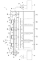
本発明の実施形態係る仕上げ処理機1は、ブロー成形された合成樹脂製ボトル(以下、ボトルという)に、ブロー成形後の仕上げ処理を施す処理機である。図1に示すように、仕上げ処理機1は、ボトル移送機構10、支持枠20、複数の処理ユニット21〜24を備えている。
A finishing machine 1 according to an embodiment of the present invention is a processing machine that performs a blow-molded finishing process on a blow-molded synthetic resin bottle (hereinafter referred to as a bottle). As illustrated in FIG. 1, the finishing machine 1 includes a
ボトル移送機構10は、口部を下にしたボトルWを把持して設定間隔毎に間欠直線移動させる機構を備えており、支持枠20に支持されている。ブロー成形後のボトルWは、各種の搬送手段によって仕上げ処理機1の入口部2に搬入される。入口部2には、正立状態で搬入されたボトルWを反転してボトル移送機構10の搬入位置T0に供給するボトル反転供給手段(ロボットハンドなど)3を備えている。
The
ボトル移送機構10は、ボトル停止位置で一体に開閉してボトルWの口部周辺を把持する下側把持部11と、ボトル停止位置で一体に開閉してボトルWの胴部を把持する上側把持部12を備えている。図1においては、T1,T2,T3,T4がボトル停止位置になる。また、ボトル移送機構10は、ボトル停止位置T1〜T4でボトルWの底部を押圧する底部押圧手段13を備えている。
The
入口部2からボトル移送機構10の搬入位置T0に供給されたボトルWは、ボトル停止位置T1から順次ボトル停止位置T2,T3,T4に送られ、搬出位置T5において、ボトル搬出手段4に把持されて搬出部5に送られる。図示の例では、ボトル搬出手段4は、口部を下にしたボトルWを反転して搬出部5に正立状態で送る装置(ロボットハンドなど)である。ボトル移送機構10は、各ボトル停止位置T1〜T4において、一定時間ボトルWを保持して、次のボトル停止位置に移送する。
The bottle W supplied from the
仕上げ処理機1は、ボトル移送機構10のボトル停止位置T1〜T4に対応して複数の処理ユニット21,22,23,24を配置している。複数の処理ユニット21〜24は、支持枠20によってボトル停止位置T1〜T4毎に直線的に配列、支持されており、ブロー成形後のボトルWに対して、余剰頭部の切断(ラフカット処理)、口部の仕上げ切削(リーミング処理)、ボトル内部の屑の吹き出し(チップブロー処理)などの異なる仕上げ処理を行うための各処理ステーションを構成している。
The finishing machine 1 has a plurality of
このような仕上げ処理機1によると、ボトル移送機構10の搬入位置T0に供給された一つのボトルWは、先ず第1のボトル停止位置T1で、処理ユニット21によって第1の仕上げ処理が行われ、第2のボトル停止位置T2に移送された後、そこで処理ユニット22によって第2の仕上げ処理が行われ、第3のボトル停止位置T3に移送された後、そこで処理ユニット23によって第3の仕上げ処理が行われ、第4のボトル停止位置T4に移送された後、そこで処理ユニット24よって第4の仕上げ処理が行われる。そして、複数の異なる仕上げ処理が行われたボトルWは、搬出位置T5から搬出部5に搬出される。
According to such a finishing machine 1, one bottle W supplied to the carry-in
一つのボトルWが第1のボトル停止位置T1から第2のボトル停止位置T2に移送される際に、第1のボトル停止位置T1には新たな未処理のボトルWが供給され、ボトルWが一つのボトル停止位置から次のボトル停止位置に移動する毎に新たな未処理のボトルWがボトル移送機構10に供給される。これによって、異なるボトル停止位置T1〜T4でそれぞれ把持されている複数のボトルWに対しては、ボトルの停止時間内でそれぞれ異なる処理が行われる。
When one bottle W is transferred from the first bottle stop position T1 to the second bottle stop position T2, a new unprocessed bottle W is supplied to the first bottle stop position T1, and the bottle W A new unprocessed bottle W is supplied to the
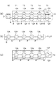
図2及び図3は、ボトル移送機構10の動作例を示している。ここでは、具体的な機構を示していないが、サーボモータとボールネジとの組み合わせやサーボモータとリンク機構との組み合わせ、或いはエアシリンダなどで、下側把持部11と上側把持部12の直線的な移動を実現することができる。
2 and 3 show an operation example of the
下側把持部11は、前述したボトル停止位置T1〜T4に対応して、一体に開閉動作する複数の把持部11Aを備えており、上側把持部12は、一体に開閉動作すると共に、前述した複数の把持部11Aの配列方向に沿って往復移動する複数の把持部12Aを備えている。下側把持部11の把持部11Aと上側把持部12の把持部12Aは同じ間隔で配置されており、把持部12Aの数が把持部11Aの数より1つ多く設定されている。これにより、上側把持部12は、搬入位置T0にあるボトルWをボトル停止位置T1に取り込む機能を有すると共に、ボトル停止位置T4にあるボトルWを搬出位置T5に送り出す機能を有している。
The
そして、下側把持部11は、ボトル停止位置T1〜T4で一体に開閉してボトルの口部周辺を把持するのに対して、上側把持部12は、処理ユニット21〜24の処理動作時に、下側把持部11と共に閉じてボトルWを把持し、下側把持部11の開時にボトルWを把持した状態で設定間隔だけボトルWを移送させ、下側把持部11の閉時に開いて設定間隔だけ戻る動作を行う。
And while the
図2(a)に示すように、第1のボトルWが搬入位置T0に供給されると、上側把持部12は、開いた状態で図示左側に移動し、図2(b)に示すように、第1のボトルWを搬入位置T0にて把持する。その後、図2(c)に示すように、下側把持部11が開いた状態になり、上側把持部12は、図示右側に移動して、第1のボトルWをボトル停止位置T1に移動する。次に、図2(d)に示すように、第2のボトルWが搬入位置T0に供給されると、下側把持部11が閉じ、第1のボトルWを把持した状態で、上側把持部12は、再び開いた状態になる。そして、図2(e)に示すように、上側把持部12は、開いた状態で図示左側に移動し、搬入位置T0で第2のボトルWを把持すると共に、ボトル停止位置T1で第1のボトルWを把持する。このタイミングでボトル停止位置T1にて下側把持部11及び上側把持部12によって把持された第1のボトルWに対して、第1の仕上げ処理が行われる。その後は、図2(f)に示すように、下側把持部11が開いた状態になり、上側把持部12が図示右側に移動して、第1のボトルをボトル停止位置T2に移動すると共に、第2のボトルをボトル停止位置T1に移動する。
As shown in FIG. 2A, when the first bottle W is supplied to the carry-in position T0, the
以下、通常運転時には、このような動作を繰り返し、ボトル停止位置T1〜T4にて下側把持部11及び上側把持部12によって把持されたボトルに対して、それぞれ第1〜第4の仕上げ処理が行われる。そして、図3(a)に示すように、仕上げ処理が終了し、上側把持部12が把持して移動した搬出位置T5にあるボトルWは、ボトル搬出手段4に把持され、ボトルWが搬入位置T0に供給されると、上側把持部12が開いた後にボトル搬出手段4から搬出部5に送られる。次に、図3(b)に示すように、上側把持部12によって搬入位置T0のボトルWを把持し、下側把持部11及び上側把持部12によって把持したボトル停止位置T1〜T4のボトルWに対して、第1〜第4の仕上げ処理が行われる。その後は、図3(c)に示すように、下側把持部11が開き、上側把持部12によってボトルWを把持して移動する。このように、前述した図2(a)〜(c)と同様の動作が行われ、その後は、この動作が繰り返される。
Hereinafter, during normal operation, such operations are repeated, and the first to fourth finishing processes are performed on the bottles gripped by the
図4は、各処理ユニットの具体例を示している。この例では、第1の処理ユニット21として、ボトルWの余剰頭部を切断する切断ユニット21Pが配備され、第2の処理ユニット22として、ボトルWの口部を粗切削する粗切削ユニット22Pが配備され、第3の処理ユニット23として、ボトルWの口部を仕上げ切削する仕上げ切削ユニット23Pが配置され、第4の処理ユニット24として、ボトルW内部の屑を吹き出す屑吹き出しユニット24Pが配備されている。
FIG. 4 shows a specific example of each processing unit. In this example, a
この例では、1つのボトルWに対して行われるリーミング処理として、粗切削ユニット22Pによる第1リーミング処理と、その後行われる仕上げ切削ユニット23Pによる第2リーミング処理とがなされる。また、粗切削ユニット22Pの前段に切断ユニット21Pを設けることで、リーミング処理に先立ってラフカット処理が行われ、仕上げ切削ユニット23Pの後段に屑吹き出しユニット24Pを設けることで、リーミング処理後にチップブロー処理が行われる。
In this example, as the reaming process performed on one bottle W, the first reaming process by the
図4に示した例でも、ボトル移送機構10は、第1〜第4の処理ユニット21〜24が配置されるボトル停止位置でボトルWの底部を上から押圧する底部押圧手段13を備えている。このような底部押圧手段13を設けることで、ボトルWを安定した状態で位置決めして、精度良く各処理を行うことができる。
Also in the example illustrated in FIG. 4, the
本発明の実施形態に係る仕上げ処理機1は、支持枠20に対して直線的に配列される複数の処理ユニット21〜24を適宜の処理に対応させることで、様々なボトルに対して求められる異なる種類の仕上げ処理を任意に設定することができる。また、支持枠20の支持スペースやボトル移送機構10の把持部の数を適宜増設することで、処理ユニットの増設を簡易且つ省スペースで実現することができる。
The finishing machine 1 according to the embodiment of the present invention is required for various bottles by causing the plurality of
以上、本発明の実施の形態について図面を参照して詳述してきたが、具体的な構成はこれらの実施の形態に限られるものではなく、本発明の要旨を逸脱しない範囲の設計の変更等があっても本発明に含まれる。また、上述の各実施の形態は、その目的及び構成等に特に矛盾や問題がない限り、互いの技術を流用して組み合わせることが可能である。 As described above, the embodiments of the present invention have been described in detail with reference to the drawings. However, the specific configuration is not limited to these embodiments, and the design can be changed without departing from the scope of the present invention. Is included in the present invention. In addition, the above-described embodiments can be combined by utilizing each other's technology as long as there is no particular contradiction or problem in the purpose and configuration.
1:仕上げ処理機,2:入口部,3:ボトル反転供給手段,
4:ボトル搬出手段,5:搬出部,
10:ボトル移送機構,11:下側把持部,12:上側把持部,
13:底部押圧手段,
20:支持枠,21〜24:処理ユニット,
21P:切断ユニット,22P:粗切削ユニット,23P:切削ユニット,
24P:屑吹き出しユニット,
W:ボトル,T0:搬入位置,T1〜T4:ボトル停止位置,
T5:搬出位置
1: Finishing machine, 2: Inlet part, 3: Bottle inversion supply means,
4: Bottle unloading means, 5: Unloading section,
10: Bottle transfer mechanism, 11: Lower gripping part, 12: Upper gripping part,
13: Bottom pressing means
20: Support frame, 21-24: Processing unit,
21P: Cutting unit, 22P: Rough cutting unit, 23P: Cutting unit,
24P: Waste blowing unit,
W: Bottle, T0: Loading position, T1-T4: Bottle stop position,
T5: Unloading position
Claims (7)
口部を下にしたボトルを把持して設定間隔毎に間欠直線移動させるボトル移送機構と、
前記ボトル移送機構のボトル停止位置に対応して配置され、各停止位置で前記ボトル移送機構に把持されたボトルに異なる仕上げ処理を行う複数の処理ユニットと、
前記ボトル移送機構を支持すると共に、前記複数の処理ユニットを直線的に配列支持する支持枠とを備えること特徴とする合成樹脂製ボトルの仕上げ処理機。 A finishing machine that performs a finishing process on a blow-molded bottle,
A bottle transfer mechanism that grips the bottle with the mouth down and moves it intermittently at set intervals;
A plurality of processing units that are arranged corresponding to the bottle stop positions of the bottle transfer mechanism and perform different finishing processes on the bottles held by the bottle transfer mechanism at each stop position;
A synthetic resin bottle finishing machine comprising: a support frame for supporting the bottle transfer mechanism and linearly arranging and supporting the plurality of processing units.
仕上げ処理後のボトルを搬出する搬出部とを備え、
前記入口部は、正立状態で搬入されたボトルを反転して前記ボトル移送機構に供給するボトル反転供給手段を備えることを特徴とする請求項1に記載された合成樹脂製ボトルの仕上げ処理機。 An inlet part into which a molded bottle is carried;
An unloading section for unloading the bottle after finishing processing,
2. The synthetic resin bottle finisher according to claim 1, wherein the inlet portion includes a bottle inversion supply unit that inverts a bottle carried in an upright state and supplies the bottle to the bottle transfer mechanism. .
前記上側把持部は、前記処理ユニットの処理動作時に、前記下側把持部と共に閉じてボトルを把持し、前記下側把持部の開時にボトルを把持した状態で前記設定間隔だけボトルを移送させ、前記下側把持部の閉時に開いて前記設定間隔だけ戻る動作を行うことを特徴とする請求項1又は2に記載された合成樹脂製ボトルの仕上げ処理機。 The bottle transfer mechanism includes a lower gripping portion that opens and closes integrally at the bottle stop position and grips the periphery of the mouth of the bottle, and an upper gripping portion that opens and closes integrally at the bottle stop position and grips the bottle body. With
The upper gripping part is closed with the lower gripping part during the processing operation of the processing unit to grip the bottle, and the bottle is transported by the set interval while gripping the bottle when the lower gripping part is opened, 3. The synthetic resin bottle finishing machine according to claim 1, wherein when the lower gripping portion is closed, an operation of opening and returning by the set interval is performed. 4.
Priority Applications (1)
| Application Number | Priority Date | Filing Date | Title |
|---|---|---|---|
| JP2016157651A JP6840954B2 (en) | 2016-08-10 | 2016-08-10 | Synthetic resin bottle finishing machine |
Applications Claiming Priority (1)
| Application Number | Priority Date | Filing Date | Title |
|---|---|---|---|
| JP2016157651A JP6840954B2 (en) | 2016-08-10 | 2016-08-10 | Synthetic resin bottle finishing machine |
Publications (2)
| Publication Number | Publication Date |
|---|---|
| JP2018024175A true JP2018024175A (en) | 2018-02-15 |
| JP6840954B2 JP6840954B2 (en) | 2021-03-10 |
Family
ID=61194945
Family Applications (1)
| Application Number | Title | Priority Date | Filing Date |
|---|---|---|---|
| JP2016157651A Active JP6840954B2 (en) | 2016-08-10 | 2016-08-10 | Synthetic resin bottle finishing machine |
Country Status (1)
| Country | Link |
|---|---|
| JP (1) | JP6840954B2 (en) |
-
2016
- 2016-08-10 JP JP2016157651A patent/JP6840954B2/en active Active
Also Published As
| Publication number | Publication date |
|---|---|
| JP6840954B2 (en) | 2021-03-10 |
Similar Documents
| Publication | Publication Date | Title |
|---|---|---|
| TWI516357B (en) | A blow molding method of a handle container and a blow molding apparatus | |
| CN100581677C (en) | Device for continuously performing localized and/or extended deformations on metal containers | |
| KR20160128224A (en) | Cutting apparatus | |
| JP2014188672A (en) | Method of discharging work piece from process machine, and process machine | |
| CN106079381A (en) | Method that preform homoiothermic processes and firing equipment and blow molding machine | |
| KR20160128223A (en) | Cutting apparatus | |
| CN112689551B (en) | Device with a first and a second robot and method for operating the device | |
| JP2012110997A (en) | Machine tool system and its workpiece transfer method | |
| US6634265B2 (en) | Apparatus for exchanging workpieces | |
| JP5045526B2 (en) | Resin molded product finishing processing method and resin molded product finishing processing apparatus | |
| CN105636860A (en) | Production system and method for manufacturing different body-in-white component variants | |
| JP6840954B2 (en) | Synthetic resin bottle finishing machine | |
| JP2009173446A (en) | Conveying wheel, can manufacturing apparatus, and can manufacturing method | |
| KR101069909B1 (en) | Automatic Molding Device for Muffler Flange | |
| JP2004216404A (en) | Press production facility and pressing method | |
| KR101953465B1 (en) | Scrap removal device for automobile blow molding products | |
| KR101953466B1 (en) | Processing device of automobile blow molding products | |
| CN117961051A (en) | A die casting production line and process | |
| CN101167172B (en) | Method and device for supplying and unloading carriers with electronic components | |
| CN104495354B (en) | A kind of robot transfer matic loading and unloading carrying method | |
| JP3552769B2 (en) | Apparatus and method for cutting molded articles | |
| US20060117707A1 (en) | Apparatus for producing core assemblies | |
| JPH0890662A (en) | Cooling and conveying device of molded product | |
| JP3254096B2 (en) | Manufacturing method and manufacturing apparatus for cylinder block mold core | |
| JP2000271796A (en) | Processing method of transfer press line |
Legal Events
| Date | Code | Title | Description |
|---|---|---|---|
| A621 | Written request for application examination |
Free format text: JAPANESE INTERMEDIATE CODE: A621 Effective date: 20190717 |
|
| A977 | Report on retrieval |
Free format text: JAPANESE INTERMEDIATE CODE: A971007 Effective date: 20200525 |
|
| A131 | Notification of reasons for refusal |
Free format text: JAPANESE INTERMEDIATE CODE: A131 Effective date: 20200616 |
|
| TRDD | Decision of grant or rejection written | ||
| A01 | Written decision to grant a patent or to grant a registration (utility model) |
Free format text: JAPANESE INTERMEDIATE CODE: A01 Effective date: 20210119 |
|
| A61 | First payment of annual fees (during grant procedure) |
Free format text: JAPANESE INTERMEDIATE CODE: A61 Effective date: 20210201 |
|
| R150 | Certificate of patent or registration of utility model |
Ref document number: 6840954 Country of ref document: JP Free format text: JAPANESE INTERMEDIATE CODE: R150 |