JP2018024896A - Manufacturing method of reduced iron, manufacturing method of molten steel and blast furnace iron mill including reduced iron manufacturing process - Google Patents
Manufacturing method of reduced iron, manufacturing method of molten steel and blast furnace iron mill including reduced iron manufacturing process Download PDFInfo
- Publication number
- JP2018024896A JP2018024896A JP2016155249A JP2016155249A JP2018024896A JP 2018024896 A JP2018024896 A JP 2018024896A JP 2016155249 A JP2016155249 A JP 2016155249A JP 2016155249 A JP2016155249 A JP 2016155249A JP 2018024896 A JP2018024896 A JP 2018024896A
- Authority
- JP
- Japan
- Prior art keywords
- furnace
- blast furnace
- cog
- reduced iron
- produced
- Prior art date
- Legal status (The legal status is an assumption and is not a legal conclusion. Google has not performed a legal analysis and makes no representation as to the accuracy of the status listed.)
- Granted
Links
Images

Classifications
-
- Y—GENERAL TAGGING OF NEW TECHNOLOGICAL DEVELOPMENTS; GENERAL TAGGING OF CROSS-SECTIONAL TECHNOLOGIES SPANNING OVER SEVERAL SECTIONS OF THE IPC; TECHNICAL SUBJECTS COVERED BY FORMER USPC CROSS-REFERENCE ART COLLECTIONS [XRACs] AND DIGESTS
- Y02—TECHNOLOGIES OR APPLICATIONS FOR MITIGATION OR ADAPTATION AGAINST CLIMATE CHANGE
- Y02P—CLIMATE CHANGE MITIGATION TECHNOLOGIES IN THE PRODUCTION OR PROCESSING OF GOODS
- Y02P10/00—Technologies related to metal processing
- Y02P10/10—Reduction of greenhouse gas [GHG] emissions
- Y02P10/143—Reduction of greenhouse gas [GHG] emissions of methane [CH4]
Landscapes
- Manufacture Of Iron (AREA)
- Waste-Gas Treatment And Other Accessory Devices For Furnaces (AREA)
Abstract
【課題】高炉を備えた製鉄プロセスから排出される還元性ガスであるCOGを還元材として有効活用し、製鉄所におけるエネルギー利用の最適化を図るとともに、将来的な原料の劣質化にも対応できるようにする。【解決手段】高炉2を備えた製鉄所1において、高炉2へ供給するコークスを製造するコークス炉4で副生されるコークス炉ガスを還元材として用いて、シャフト炉11または流動層式還元炉で還元鉄を製造し、高炉2の出銑能力から、高炉2へ供給するコークス量を求め、次に、そのコークス量を製造する際に副生されるコークス炉ガス量を求め、次に、シャフト炉11または流動層式還元炉において、そのコークス炉ガス量で還元できる還元鉄量に応じて、シャフト炉11または流動層式還元炉の設備能力を決定する。【選択図】図2[PROBLEMS] To effectively utilize COG, which is a reducing gas discharged from a steelmaking process equipped with a blast furnace, as a reducing material, to optimize the use of energy at a steelworks and to cope with future deterioration of raw materials. Like that. In a steelworks 1 equipped with a blast furnace 2, a coke oven gas produced as a by-product in a coke oven 4 for producing coke supplied to the blast furnace 2 is used as a reducing material, and a shaft furnace 11 or a fluidized bed type reduction furnace. The reduced iron is produced by the above, and the amount of coke supplied to the blast furnace 2 is obtained from the output capacity of the blast furnace 2, and then the amount of coke oven gas produced as a by-product when producing the amount of coke is obtained. In the shaft furnace 11 or the fluidized bed type reducing furnace, the equipment capacity of the shaft furnace 11 or the fluidized bed type reducing furnace is determined according to the amount of reduced iron that can be reduced with the amount of coke oven gas. [Selection] Figure 2
Description
本発明は、還元鉄の製造方法および溶鋼の製造方法ならびに還元鉄製造工程を含む高炉製鉄所に関し、詳しくは、高炉と、コークス炉ガスを還元材として用いるシャフト炉または流動層式還元炉とを組み合わせて還元鉄や溶鋼を製造する方法および高炉製鉄所に関する。 TECHNICAL FIELD The present invention relates to a method for producing reduced iron, a method for producing molten steel, and a blast furnace ironworks including a reduced iron production process. Specifically, a blast furnace and a shaft furnace or a fluidized bed type reduction furnace using coke oven gas as a reducing material. The present invention relates to a method for producing reduced iron or molten steel in combination and a blast furnace steel works.
大型高炉を基軸とした大規模高炉法では、焼結炉で鉄鉱石を焼成した焼結鉱と、コークス炉で原料炭を蒸し焼きにして製造したコークスとを高炉に装入して溶銑を製造し、溶銑を転炉で酸素精錬して溶鋼を生産する。その際、コークス炉で発生するコークス炉ガス(COG)と高炉で発生する高炉ガス(BFG)は、従来、熱延等の下工程の加熱炉や自家発電の燃料として使用されている。 In a large-scale blast furnace method based on a large blast furnace, molten iron is produced by charging a blast furnace with sintered ore fired from iron ore in a sintering furnace and coke produced by steaming coking coal in a coke furnace. The hot metal is refined with oxygen in a converter to produce molten steel. At that time, coke oven gas (COG) generated in the coke oven and blast furnace gas (BFG) generated in the blast furnace are conventionally used as a heating furnace in a lower process such as hot rolling or as a fuel for private power generation.
ところが、大型高炉プロセスでは、良質の鉄鉱石や良質の原料炭をそれぞれ一定割合以上配合しないと操業が不安定となるため、近い将来予測される原料の劣質化に直面した際に、操業諸元が悪化したり操業が困難になったりする懸念がある。例えば、焼結鉱の強度確保の観点から、粉鉱の配合比率には限界がある。そこで、近い将来に予想される国内で入手可能な鉄鉱石や原料炭等の原料の劣質化を踏まえると、現在主流となっている大型高炉と良質原料とによる高効率製鉄法が将来にわたって永続する可能性は小さく、劣質原料を使用可能なシャフト炉等のプロセスを併用する必要が生じてくると考えられる。 However, in the large blast furnace process, if high-quality iron ore and high-quality coking coal are not mixed at a certain ratio or more, the operation becomes unstable. There is a concern that it will worsen and operation will become difficult. For example, from the viewpoint of securing the strength of sintered ore, there is a limit to the blending ratio of fine ore. Therefore, taking into account the deterioration of raw materials such as iron ore and coking coal that are expected to be available in Japan in the near future, the high-efficiency ironmaking method using large blast furnaces and high-quality raw materials that will become the mainstream will last in the future. The possibility is small, and it will be necessary to use a process such as a shaft furnace that can use inferior raw materials.
また、COGは水素を約50〜55%含み、単体で酸化鉄を還元する能力を有する強還元性ガスであり、燃料として燃焼させるだけでは、COGの価値を十分に活用しきれていない。つまり、現在の高炉法は、製鉄プロセスとして最適化の余地が残された状態となっている。 Further, COG is a strongly reducing gas containing about 50 to 55% of hydrogen and capable of reducing iron oxide alone, and the value of COG cannot be fully utilized only by burning it as fuel. In other words, the current blast furnace method leaves room for optimization as a steelmaking process.
特許文献1には、石炭ガス化プロセスの排ガスの熱を廃熱ボイラーによって回収して蒸気を生成し、その蒸気を直接製鉄プロセスの排ガスで過熱し、過熱蒸気を酸化剤として石炭ガス化炉に供給すること、また、石炭ガス化で生成された生成ガスを、直接製鉄プロセスの加熱還元炉に燃料として供給する方法が記載されている。 In Patent Document 1, the heat of the exhaust gas from the coal gasification process is recovered by a waste heat boiler to generate steam, and the steam is directly heated by the exhaust gas from the iron making process, and the superheated steam is used as an oxidizing agent in the coal gasification furnace. A method is described in which the product gas produced by coal gasification is supplied as fuel directly to the heating and reduction furnace of the iron making process.
特許文献2には、ランス付き竪型ガス化炉で固体状炭素物質に酸素を吹き込んでガス化させ、当該ガスと鉄鉱石類を600℃以上に加熱して金属化率が0.4以上0.8以下の予備還元物を製造し、その予備還元物を粗粒と微粒とに分級し、微粒分を塊成化する予備還元塊成化物の製造方法が開示されている。
In
特許文献3には、COGを用いて酸化鉄を金属鉄に還元する直接還元シャフト炉が開示されている。特許文献4には、コークス炉ガス(COG)及び塩基性酸素製鋼炉ガス(BOFG)を用いて酸化鉄を金属鉄に還元する直接還元シャフト炉が開示され、BOFGの混合物から二酸化炭素を除去することが記載されている。
特許文献5には、直接還元法を使用して鉄鉱を還元する方法として、排ガスに還元ガスを追加した後、電気で再加熱して還元ガスとして再利用される方法が開示されている。
特許文献6には、製鉄プロセスで発生するH2及びCOの少なくとも一方を含む副生ガスを一部として含む還元ガスを還元鉄製造装置に供給する還元鉄の製造方法が開示され、副生ガスが、コークス炉より発生した副生ガスを含むことが記載されている。 Patent Document 6 discloses a method for producing reduced iron that supplies a reduced gas containing a by-product gas containing at least one of H 2 and CO generated in an iron making process as a part to a reduced iron production apparatus. Is described as containing by-product gas generated from a coke oven.
ところが、上記特許文献1は、石炭ガス化の排ガスをボイラーや熱交換を通して蒸気を生成するものであり、製鉄プロセスから排出される還元性ガスであるCOGの有効利用に関するものではない。また、蒸気を過熱するために回転炉床炉(RHF)の排ガスを使用しているが、直接還元プロセスである必然性はない。 However, the above-mentioned Patent Document 1 generates steam through coal gasification exhaust gas through a boiler or heat exchange, and does not relate to effective use of COG, which is a reducing gas discharged from the iron making process. Moreover, although the exhaust gas of a rotary hearth furnace (RHF) is used to superheat the steam, it is not necessarily a direct reduction process.
特許文献2は、石炭由来の還元性ガスを用いてシャフト炉等で鉄鉱石を還元するものであるが、還元性ガスを生成するために、新たに固体状炭素物質を用いる必要がある。
In
また、特許文献3および特許文献4は、シャフト炉やその周辺の設備に関するものであり、高炉由来で副生されたCOGをシャフト炉で有効利用することに関するものではない。特許文献5もまた、高炉を備えた設備から副生されるCOGの有効利用に関するものではない。
特許文献6には、COG等の副生ガスの他、天然ガスや一般炭をガス化したガスを含めて、還元ガスとして改質することが記載されており、高炉を備えた設備から副生されるCOG量をシャフト炉に過不足なく有効活用することに関するものではない。 Patent Document 6 describes reforming as a reducing gas, including by-product gas such as COG, as well as gas obtained from gasification of natural gas and steam coal, and by-product from equipment equipped with a blast furnace. It is not related to the effective utilization of the amount of COG produced in the shaft furnace without excess or deficiency.
本発明の目的は、高炉を備えた製鉄プロセスから排出される還元性ガスであるCOGを還元材として有効活用し、製鉄所におけるエネルギー利用の最適化を図るとともに、将来的な原料の劣質化にも対応できるようにすることにある。 The purpose of the present invention is to effectively utilize COG, which is a reducing gas discharged from an ironmaking process equipped with a blast furnace, as a reducing material, to optimize energy use in steelworks, and to reduce the quality of raw materials in the future. Is to be able to cope.
上記問題を解決するため、本発明は、高炉を備えた製鉄所において、前記高炉へ供給するコークスを製造するコークス炉で副生されるコークス炉ガスを還元材として用いて、シャフト炉または流動層式還元炉で還元鉄を製造し、前記高炉の出銑能力から、前記高炉へ供給するコークス量を求め、次に、前記コークス量を製造する際に副生されるコークス炉ガス量を求め、次に、前記シャフト炉または流動層式還元炉において、前記コークス炉ガス量で還元できる還元鉄量に応じて、当該シャフト炉または流動層式還元炉の設備能力を決定することを特徴とする、還元鉄の製造方法を提供する。 In order to solve the above problems, the present invention provides a shaft furnace or a fluidized bed using, as a reducing material, a coke oven gas produced as a by-product in a coke oven for producing coke to be supplied to the blast furnace in an iron works equipped with a blast furnace. Reduced iron is produced in a reduction furnace, and the amount of coke supplied to the blast furnace is determined from the output capacity of the blast furnace, and then the amount of coke oven gas produced as a by-product when the amount of coke is produced, Next, in the shaft furnace or the fluidized bed type reduction furnace, the facility capacity of the shaft furnace or the fluidized bed type reduction furnace is determined according to the amount of reduced iron that can be reduced by the coke oven gas amount. A method for producing reduced iron is provided.
前記還元鉄の製造方法において、前記シャフト炉または流動層式還元炉の設備能力PD(t/Yr)は、以下の式で求めてもよい。
PD=PP×FCOG×((CCO+CH2+3×CCH4)÷100)×(η÷100)÷FO÷22.4×16.0 ・・・(1)
ここで、
PP:高炉出銑能力(t/Yr)
FCOG:高炉における溶銑1tあたりのCOG発生量(Nm3/t)
CCO:COG中のCO含有率(体積%)
CH2:COG中のH2含有率(体積%)
CCH4:COG中のCH4含有率(体積%)
η:シャフト炉または流動層式還元炉におけるCOGの利用効率(%)
FO:シャフト炉または流動層式還元炉において、還元鉄を1t製造する際に取り除く必要のある酸素の質量(kg−O2/t)
なお、FOは、シャフト炉または流動層式還元炉において使用する鉱石の品位および製品還元鉄の目標還元率によって決まる。
In the method for producing reduced iron, the equipment capacity P D (t / Yr) of the shaft furnace or fluidized bed type reduction furnace may be obtained by the following equation.
P D = P P × F COG × ((C CO + CH 2 + 3 × C CH 4 ) ÷ 100) × (η ÷ 100) ÷ F O ÷ 22.4 × 16.0 (1)
here,
P P : Blast furnace tapping capacity (t / Yr)
F COG : COG generation amount per ton of hot metal in the blast furnace (Nm 3 / t)
C CO : CO content in COG (% by volume)
C H2 : H 2 content in COG (% by volume)
C CH4 : CH 4 content (% by volume) in COG
η: COG utilization efficiency in shaft furnace or fluidized bed type reduction furnace (%)
F O: In a shaft furnace or a fluidized bed reduction furnace, the reduced iron mass of oxygen that must be removed when 1t produced (kg-
Note that FO is determined by the quality of the ore used in the shaft furnace or the fluidized bed reduction furnace and the target reduction rate of the product reduced iron.
また、本発明は、前記還元鉄の製造方法で製造した還元鉄と、前記高炉で製造した溶銑とを混合して精錬炉へ投入し、仕上げ還元および精錬を行うことを特徴とする、溶鋼の製造方法を提供する。 Further, the present invention is characterized in that the reduced iron produced by the method for producing reduced iron and the molten iron produced in the blast furnace are mixed and put into a refining furnace, and finish reduction and refining are performed. A manufacturing method is provided.
また、前記還元鉄の製造方法で製造した還元鉄を熱間成型してHBIとし、前記HBIを前記高炉の原料として前記高炉で製造した溶銑を精錬炉へ投入し、仕上げ還元および精錬を行うことを特徴とする、溶鋼の製造方法を提供する。 Further, the reduced iron produced by the method for producing reduced iron is hot-molded into HBI, and the hot metal produced in the blast furnace is charged into the smelting furnace using the HBI as a raw material for the blast furnace, and finish reduction and refining are performed. A method for producing molten steel is provided.
さらに、前記還元鉄の製造方法で製造した還元鉄を熱間成型してHBIとし、前記HBIを篩処理し、篩上分を前記高炉の原料とし、篩下分を前記高炉で製造した溶銑と混合して精錬炉へ投入し、仕上げ還元および精錬を行うことを特徴とする、溶鋼の製造方法を提供する。 Furthermore, the reduced iron produced by the method for producing reduced iron is hot-molded to form HBI, the HBI is sieved, the sieving portion is used as the raw material of the blast furnace, and the molten iron produced in the blast furnace is used as the hot metal. Provided is a method for producing molten steel, which is mixed and charged into a refining furnace to perform finish reduction and refining.
さらに、本発明は、高炉を備えた製鉄所において、前記高炉へ供給するコークスを製造するコークス炉と、前記コークス炉で副生されるコークス炉ガスを還元材として用いて還元鉄を製造するシャフト炉または流動層式還元炉とを備え、前記シャフト炉または流動層式還元炉は、前記高炉の出銑能力から求められる前記高炉へ供給すべきコークス量を製造する際に副生されるコークス炉ガス量で還元できる還元鉄量に応じた設備能力を有することを特徴とする、還元鉄製造工程を含む高炉製鉄所を提供する。 Furthermore, the present invention provides a coke oven for producing coke to be supplied to the blast furnace, and a shaft for producing reduced iron using a coke oven gas by-produced in the coke oven as a reducing material in an ironworks equipped with a blast furnace. A coke oven that is by-produced when producing the amount of coke to be supplied to the blast furnace, which is obtained from the output capacity of the blast furnace. Provided is a blast furnace steelworks including a reduced iron production process, which has a facility capacity corresponding to the amount of reduced iron that can be reduced by a gas amount.
前記還元鉄製造工程を含む高炉製鉄所において、前記シャフト炉または流動層式還元炉の設備能力PD(t/Yr)は、以下の式で求めてもよい。
PD=PP×FCOG×((CCO+CH2+3×CCH4)÷100)×(η÷100)÷FO÷22.4×16.0 ・・・(1)
ここで、
PP:高炉出銑能力(t/Yr)
FCOG:高炉における溶銑1tあたりのCOG発生量(Nm3/t)
CCO:COG中のCO含有率(体積%)
CH2:COG中のH2含有率(体積%)
CCH4:COG中のCH4含有率(体積%)
η:シャフト炉または流動層式還元炉におけるCOGの利用効率(%)
FO:シャフト炉または流動層式還元炉において、還元鉄を1t製造する際に取り除く必要のある酸素の質量(kg−O2/t)
In the blast furnace steelworks including the reduced iron manufacturing process, the facility capacity P D (t / Yr) of the shaft furnace or fluidized bed type reduction furnace may be obtained by the following equation.
P D = P P × F COG × ((C CO + CH 2 + 3 × C CH 4 ) ÷ 100) × (η ÷ 100) ÷ F O ÷ 22.4 × 16.0 (1)
here,
P P : Blast furnace tapping capacity (t / Yr)
F COG : COG generation amount per ton of hot metal in the blast furnace (Nm 3 / t)
C CO : CO content in COG (% by volume)
C H2 : H 2 content in COG (% by volume)
C CH4 : CH 4 content (% by volume) in COG
η: COG utilization efficiency in shaft furnace or fluidized bed type reduction furnace (%)
F O: In a shaft furnace or a fluidized bed reduction furnace, the reduced iron mass of oxygen that must be removed when 1t produced (kg-
本発明によれば、高炉を備えた製鉄所において、高炉の出銑能力に応じたシャフト炉または流動層式還元炉を設けることにより、コークス炉で副生されるCOGを過不足なく還元材として有効活用することができる。したがって、製鉄所のエネルギー利用の最適化を図るとともに、将来的な原料の劣質化にも対応できる。 According to the present invention, in a steel mill equipped with a blast furnace, by providing a shaft furnace or a fluidized bed type reduction furnace corresponding to the blast furnace's tapping capacity, COG by-produced in the coke oven can be used as a reducing material without excess or deficiency. It can be used effectively. Therefore, it is possible to optimize the energy use of the steelworks and cope with future deterioration of raw materials.
以下、本発明の実施の形態を、図を参照して説明する。なお、本明細書および図面において、実質的に同一の機能構成を有する要素においては、同一の符号を付することにより重複説明を省略する。なお、以下の実施の形態では、COGを還元材として用いる炉として竪型シャフト炉の例を記載するが、流動層式還元炉においても同様に実施することができる。 Hereinafter, embodiments of the present invention will be described with reference to the drawings. In the present specification and drawings, elements having substantially the same functional configuration are denoted by the same reference numerals, and redundant description is omitted. In the following embodiment, an example of a vertical shaft furnace is described as a furnace using COG as a reducing material, but the same can be applied to a fluidized bed type reducing furnace.
〈1.第1の実施の形態〉
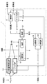
図1は、本発明の第1の実施の形態にかかる製鉄所の構成およびプロセスの概略を示す。
<1. First Embodiment>
FIG. 1 shows an outline of the structure and process of an ironworks according to a first embodiment of the present invention.
製鉄所1には高炉2が備えられ、さらに、鉄鉱石を焼成して焼結鉱を製造する焼結炉3、および原料炭からコークスを製造するコークス炉4が備えられている。焼結鉱およびコークスは高炉2に装入され、高炉2内で溶銑が製造される。溶銑は転炉5または電気炉6からなる精錬炉7で精錬され、溶鋼が生産される。高炉2で副生される高炉ガス(以下、BFGと記する)は、加熱炉9や自家発電のために発電所10の燃料として使用される。
The ironworks 1 is provided with a
本実施の形態では、このような高炉2を基軸とした製鉄所1の、高炉2と同一敷地内あるいは高炉2の設置場所に近接して、粉鉱を還元可能な竪型のシャフト炉11が設けられている。シャフト炉11には、高炉2での使用が困難な粉鉱石を例えばペレット化等により事前処理して投入され、還元材を加えて還元鉄が製造される。このようなシャフト炉11を併設することにより、製鉄所1で使用可能な原料性状の幅を拡げ、鉄鉱石や原料炭等の原料の劣質化に対応することができる。
In the present embodiment, the shaft-
シャフト炉11における還元材としては、コークス炉4で副生されるコークス炉ガス(以下、COGと記する)が用いられる。還元材として用いるCOGは、コークス炉4から排出されたままの状態でもよいし、改質してから用いてもよい。また、COGの一部は、コークス炉4や焼結炉3の燃料として利用してもよい。
As the reducing material in the
シャフト炉11の設備能力は、製鉄所1内で発生するCOGの発生量に応じた規模とする。すなわち、先ず、高炉2の出銑能力から、高炉2へ供給するために必要とするコークス量を求める。次に、そのコークス量を製造する際にコークス炉4から副生されるCOG量を求める。そして、そのCOG量のうち、シャフト炉11に供給できる量が、そのシャフト炉11で還元できる還元鉄量に必要な還元材の量とほぼ一致するような設備能力のシャフト炉11とする。このようにシャフト炉11の設備能力を決定することにより、COGを過不足なく、最も有効に活用できる。
The equipment capacity of the
従来、製鉄所では、COGを加熱炉9の燃料として利用し、還元性ガスとして利用していなかった。一方、シャフト炉11の還元材としては、天然ガスを用いたり、石炭をガス化させてCOとH2の混合ガスを合成したりしていた。本実施の形態では、従来の製鉄所でCOGを燃料としていた加熱炉や発電所には、安価な一般炭を燃料として供給する。また、高炉2で副生するBFGは、従来通り、加熱炉9や発電所10の燃料とする。これにより、強還元性ガスであるCOGを、シャフト炉11における還元ガスとして有効利用する。
Conventionally, in a steel mill, COG is used as a fuel for the
シャフト炉11で生産した還元鉄は、電気炉6または転炉5からなる精錬炉7で精錬する。すなわち、還元鉄は、そのまま電気炉6に投入するか、あるいは熱間で圧縮し固めてブリケット化し(HBI)、高炉2で製造した溶銑とともにHBIを転炉5に投入し、精錬炉7で精錬して溶鋼を製造する。
The reduced iron produced in the
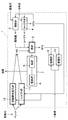
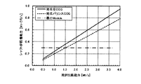
図2は、本実施の形態における高炉2の出銑能力とシャフト炉11の設備能力との関係を示す。
FIG. 2 shows the relationship between the output capacity of the
シャフト炉11で生産した還元鉄と、高炉2で製造した溶銑とを混合して精錬炉7で精錬して溶鋼を製造する場合において、高炉2の出銑能力と、高炉2へコークスを供給するコークス炉4から発生するCOGの量がちょうど還元しうる還元鉄量から推定される竪型シャフト炉11の設備能力との関係を、シミュレーションにより求めた。図2において、実線は、コークス炉4で発生するCOG全量をシャフト炉11の還元材として使用する場合であり、点線は、コークス炉4および焼結炉3で使用するCOGは優先的にそちらへ供給し、余剰分のCOGをシャフト炉11へ供給する場合を示す。一点鎖線は、既存の竪型シャフト炉の商用プロセスとしての最小能力を示す。
When reducing iron produced in the
シャフト炉または流動層式還元炉の設備能力PD(t/Yr)は、以下の式で求めた。
PD=PP×FCOG×((CCO+CH2+3×CCH4)÷100)×(η÷100)÷FO÷22.4×16.0 ・・・(1)
ここで、
PP:高炉出銑能力(t/Yr)
FCOG:高炉における溶銑1tあたりのCOG発生量(Nm3/t)
CCO:COG中のCO含有率(体積%)
CH2:COG中のH2含有率(体積%)
CCH4:COG中のCH4含有率(体積%)
η:シャフト炉または流動層式還元炉におけるCOGの利用効率(%)
FO:シャフト炉または流動層式還元炉において、還元鉄を1t製造する際に取り除く必要のある酸素の質量(kg−O2/t)
The equipment capacity P D (t / Yr) of the shaft furnace or fluidized bed type reduction furnace was determined by the following formula.
P D = P P × F COG × ((C CO + CH 2 + 3 × C CH 4 ) ÷ 100) × (η ÷ 100) ÷ F O ÷ 22.4 × 16.0 (1)
here,
P P : Blast furnace tapping capacity (t / Yr)
F COG : COG generation amount per ton of hot metal in the blast furnace (Nm 3 / t)
C CO : CO content in COG (% by volume)
C H2 : H 2 content in COG (% by volume)
C CH4 : CH 4 content (% by volume) in COG
η: COG utilization efficiency in shaft furnace or fluidized bed type reduction furnace (%)
F O: In a shaft furnace or a fluidized bed reduction furnace, the reduced iron mass of oxygen that must be removed when 1t produced (kg-
シミュレーションを実施するにあたり、コークス炉4で発生するCOG全量をシャフト炉11の還元材として使用する場合は、式(1)において、FCOG=158.3(Nm3/t)、CCO=6.5%、CH2=55%、CCH4=27%、η=75%、FO=434(kg−O2/t)とした。また、コークス炉4および焼結炉3で使用するCOGは優先的にそちらへ供給し、余剰分のCOGをシャフト炉11へ供給する場合は、式(1)において、FCOG=130.6(Nm3/t)、CCO=6.5%、CH2=55%、CCH4=27%、η=75%、FO=434(kg−O2/t)とした。
In carrying out the simulation, when the total amount of COG generated in the
製鉄所1が、ある出銑能力の高炉2を備えている場合もしくは新設する場合、その高炉2へ供給するコークスを製造するためのコークス炉4から副生するCOGを、過不足なく還元材として活用可能なシャフト炉11の設備能力は、図2に示す実線で規定される。この実線よりも大きなシャフト炉11を設置した場合、コークス炉4から副生されるCOGだけでは、必要な還元材が不足するため、別途、石炭ガス化設備や天然ガスの供給基地を構える必要が生じ、設備費が急騰する。
When the steelworks 1 has a
一方、製鉄所1において、配管設備等の都合上、コークス炉4や焼結炉3へCOG以外の燃料ガスを供給できない場合には、COGを優先的にこれらのプロセスへ供給しなければならなくなり、シャフト炉11へ供給可能なCOG量は減少する。その場合には、COGの量から求められるシャフト炉11の最大設備能力は、図2の点線まで低下する。
On the other hand, in the steelworks 1, when it is not possible to supply fuel gas other than COG to the
図2の実線または点線で示した設備能力よりも小さいシャフト炉11を設置した場合、いずれの場合においてもCOGが余剰となるが、この余剰COGは、従来通り、加熱炉9等の燃料ガスとして利用できるため、大きなデメリットが生じることにはならない。しかし、図2の一点鎖線で示した0.3(Mt−DRI/y)未満の設備能力のシャフト炉11を設置すると、炉容積に対する炉体表面積の比率が大きく、伝熱効率が悪くなるため、経済的ではない。したがって、熱経済合理性の観点から、新設するシャフト炉11の設備能力の下限は、図2の一点鎖線で示す0.3(Mt−DRI/y)以上とすることが好ましい。つまり、既設もしくは新設する高炉2の出銑能力に応じて、図2の実線または点線と一点鎖線との間の領域の設備能力を有するシャフト炉11を設置することが、還元能力を有する副生COGの有効利用の観点から好ましい。なお、この実線および点線は、高炉2におけるコークスの使用量、COGの組成、シャフト炉11で生産する還元鉄の還元率によって変化する。
When the
〈2.第2の実施の形態〉
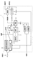
図3は、本発明にかかる第2の実施の形態を示す製鉄所の構成およびプロセスの概略を示し、図4は、第2の実施の形態における高炉2の出銑能力とシャフト炉11の設備能力との関係を示す。
<2. Second Embodiment>
FIG. 3 shows an outline of the structure and process of the steel mill showing the second embodiment according to the present invention, and FIG. 4 shows the output capacity of the
本実施の形態は、上述の図2に示す実施の形態と、製鉄所1の構成は同様であるが、図3に示すように、シャフト炉11で製造した還元鉄を熱間で圧縮しHBIとして密度と強度を高め、HBIを高炉原料として高炉2に投入する。そして高炉2で製造された溶銑を、転炉5または電気炉6からなる精錬炉7で酸素精錬して溶鋼を生産する。
This embodiment is the same as the embodiment shown in FIG. 2 described above, and the structure of the steelworks 1 is the same, but as shown in FIG. 3, the reduced iron produced in the
図4は、本実施の形態において、高炉2の出銑能力と、高炉2へコークスを供給するコークス炉4から発生するCOGの量がちょうど還元しうる還元鉄量から推定されるシャフト炉11の設備能力との関係を、シミュレーションにより求めたものである。実線、点線、および一点鎖線の意味は、図2と同様である。
FIG. 4 shows the
シミュレーションを実施するにあたり、コークス炉4で発生するCOG全量をシャフト炉11の還元材として使用する場合は、式(1)において、FCOG=134.8(Nm3/t)、CCO=6.5%、CH2=55%、CCH4=27%、η=75%、FO=434(kg−O2/t)とした。また、コークス炉4および焼結炉3で使用するCOGは優先的にそちらへ供給し、余剰分のCOGをシャフト炉11へ供給する場合は、式(1)において、FCOG=112.2(Nm3/t)、CCO=6.5%、CH2=55%、CCH4=27%、η=75%、FO=434(kg−O2/t)とした。
In carrying out the simulation, when the total amount of COG generated in the
本実施の形態の場合にも、既設もしくは新設する高炉2の出銑能力に応じて、図4の実線または点線と一点鎖線との間の領域の設備能力を有するシャフト炉11を設置することが好ましい。図4では、同じ出銑能力の高炉に併設できる最大のシャフト炉の設備能力が、図2に比べて小さくなっている。これは、還元材の消費量が少ないHBIを高炉2に投入しているため、同じ出銑量でも、高炉2で必要とする還元材(コークス)の量が少なくなり、その結果として、副生されるCOG量が少なくなるためである。
Also in the case of the present embodiment, it is possible to install the
本実施の形態の場合には、上述の第1の実施の形態に比べて、精錬炉7の操業がより安定するというメリットがある。つまり、シャフト炉11で生産された還元鉄がHBIとして高炉2へ投入されるため、精錬炉7には、高炉2から出銑された溶銑のみが供給される。したがって、精錬炉7で溶銑と還元鉄を混合したり、還元鉄の仕上げ還元反応をおこなったりする必要がないため、精錬時間が安定するだけでなく、精錬炉7内への酸化鉄の供給も最小限に抑えられ、耐火物の溶損を抑制できる。なお、本実施の形態においても、図4の実線および点線は、高炉2におけるコークスの使用量、COGの組成、シャフト炉11で生産する還元鉄の還元率によって変化する。
In the case of the present embodiment, there is a merit that the operation of the
〈3.第3の実施の形態〉
図5は、本発明にかかる第3の実施の形態を示す製鉄所の構成およびプロセスの概略を示す。
<3. Third Embodiment>
FIG. 5 shows the outline of the structure and process of an ironworks showing a third embodiment according to the present invention.
従来、シャフト炉11で還元鉄を製造する場合、上記第1の実施の形態のように、転炉5もしくは電気炉6等の精錬炉7で溶銑と混合し精錬して溶鋼とするのが一般的である。しかし、精錬炉7での還元鉄の投入割合が増加すると、シャフト炉11の操業変動によって還元鉄の還元率が変動した場合に、精錬炉7の操業が不安定となり、還元鉄の投入量に上限が生じてしまう。また、精錬炉7の操業を安定させるために高還元率を志向すると、シャフト炉11の生産性が低下してしまう懸念もある。
Conventionally, when reducing iron is produced in the
そこで、本実施の形態では、シャフト炉11で製造した還元鉄を熱間成型してHBIにし、さらに、例えば焼結鉱と同等の40〜50mm程度の篩21を用いて篩処理する。そして、篩上分(成品HBI)を焼結鉱とともに高炉原料として利用し、高炉2へ投入する。成品HBIは十分に還元されているので、高炉2内で再度還元する必要はなく、結果として安定した高炉操業を維持しながら、高炉2からの出銑量を増加させることができる。一方、篩21の篩下分(粉HBI)は未還元かつ低強度であるため、高炉原料として再利用することはできない。そこで、この粉HBIは精錬炉7へ投入し、仕上げ還元したうえで溶解する。還元率の低いHBIを精錬炉7に投入すると精錬炉7の操業が不安定となる懸念があるが、篩下分のみであれば量が少なく、影響を最小限に抑えることができる。また、精錬炉7の操業状態に応じて、粉HBIの投入の有無を調整して操業してもよい。なお、本実施の形態において、篩処理以外の製鉄所1の構成は、上述の図1、図3に示す実施の形態と同様である。
Therefore, in the present embodiment, the reduced iron produced in the
以上のように、本発明によれば、高炉2による製鉄プロセスで発生する副生ガスを過不足なく利用して、シャフト炉11による別の製鉄プロセスを効率よく操業させ、製鉄所1のエネルギー利用の最適化を図ることができる。さらに、製鉄所1内で高炉2とシャフト炉11とを併用することにより、一つの製鉄所1内で、高炉2では扱えない品質の原料から溶鋼を製造することができ、多様な原料を扱えるようになる。
As described above, according to the present invention, by-product gas generated in the iron making process by the
なお、高炉2のメンテナンス等によりCOGが副生されない場合等には、従来還元材として用いられてきた天然ガスや石炭から生成する合成ガスを、シャフト炉11の還元材として使用してもよい。
When COG is not generated as a by-product due to maintenance of the
以上、本発明の好適な実施の形態について説明したが、本発明はかかる例に限定されない。当業者であれば、特許請求の範囲に記載された技術的思想の範疇内において、各種の変更例または修正例に想到しうることは明らかであり、それらについても当然に本発明の技術的範囲に属するものと了解される。 The preferred embodiments of the present invention have been described above, but the present invention is not limited to such examples. It is obvious for those skilled in the art that various changes or modifications can be conceived within the scope of the technical idea described in the claims. It is understood that it belongs to.
例えば、上記実施の形態では、COGを還元材として用いる炉として竪型シャフト炉11の例を記載したが、流動層式還元炉12においても同様に実施することができる。
For example, in the above embodiment, an example of the
本発明は、高炉と、還元ガスにより還元鉄を製造するシャフト炉または流動層式還元炉等とを併設する製鉄所に好適である。 The present invention is suitable for an ironworks equipped with a blast furnace and a shaft furnace or a fluidized bed type reduction furnace that produces reduced iron using a reducing gas.
1 製鉄所
2 高炉
3 焼結炉
4 コークス炉
5 転炉
6 電気炉
7 精錬炉
11 シャフト炉
12 流動層式還元炉
21 篩
DESCRIPTION OF SYMBOLS 1
Claims (7)
前記高炉の出銑能力から、前記高炉へ供給するコークス量を求め、
次に、前記コークス量を製造する際に副生されるコークス炉ガス量を求め、
次に、前記シャフト炉または流動層式還元炉において、前記コークス炉ガス量で還元できる還元鉄量に応じて、当該シャフト炉または流動層式還元炉の設備能力を決定することを特徴とする、還元鉄の製造方法。 In a steelworks equipped with a blast furnace, coke oven gas produced as a by-product in a coke oven for producing coke supplied to the blast furnace is used as a reducing material, and reduced iron is produced in a shaft furnace or a fluidized bed type reduction furnace,
From the output capacity of the blast furnace, obtain the amount of coke to be supplied to the blast furnace,
Next, determine the amount of coke oven gas produced as a by-product when producing the amount of coke,
Next, in the shaft furnace or the fluidized bed type reduction furnace, the facility capacity of the shaft furnace or the fluidized bed type reduction furnace is determined according to the amount of reduced iron that can be reduced by the coke oven gas amount. A method for producing reduced iron.
PD=PP×FCOG×((CCO+CH2+3×CCH4)÷100)×(η÷100)÷FO÷22.4×16.0 ・・・(1)
ここで、
PP:高炉出銑能力(t/Yr)
FCOG:高炉における溶銑1tあたりのCOG発生量(Nm3/t)
CCO:COG中のCO含有率(体積%)
CH2:COG中のH2含有率(体積%)
CCH4:COG中のCH4含有率(体積%)
η:シャフト炉または流動層式還元炉におけるCOGの利用効率(%)
FO:シャフト炉または流動層式還元炉において、還元鉄を1t製造する際に取り除く必要のある酸素の質量(kg−O2/t) The method for producing reduced iron according to claim 1, wherein the equipment capacity P D (t / Yr) of the shaft furnace or the fluidized bed type reduction furnace is obtained by the following formula.
P D = P P × F COG × ((C CO + CH 2 + 3 × C CH 4 ) ÷ 100) × (η ÷ 100) ÷ F O ÷ 22.4 × 16.0 (1)
here,
P P : Blast furnace tapping capacity (t / Yr)
F COG : COG generation amount per ton of hot metal in the blast furnace (Nm 3 / t)
C CO : CO content in COG (% by volume)
C H2 : H 2 content in COG (% by volume)
C CH4 : CH 4 content (% by volume) in COG
η: COG utilization efficiency in shaft furnace or fluidized bed type reduction furnace (%)
F O: the shaft furnace or a fluidized bed reduction furnace, the reduced iron mass of oxygen that must be removed when 1t produced (kg-O 2 / t)
前記シャフト炉または流動層式還元炉は、
前記高炉の出銑能力から求められる前記高炉へ供給すべきコークス量を製造する際に副生されるコークス炉ガス量で還元できる還元鉄量に応じた設備能力を有することを特徴とする、還元鉄製造工程を含む高炉製鉄所。 In a steelworks equipped with a blast furnace, a coke oven that produces coke to be supplied to the blast furnace, and a shaft furnace or fluidized bed type reduction that produces reduced iron using coke oven gas by-produced in the coke oven as a reducing material. A furnace,
The shaft furnace or fluidized bed type reduction furnace is
It has a facility capacity according to the amount of reduced iron that can be reduced by the amount of coke oven gas produced as a by-product when producing the amount of coke to be supplied to the blast furnace, which is obtained from the output capacity of the blast furnace. Blast furnace steelworks including iron manufacturing process.
PD=PP×FCOG×((CCO+CH2+3×CCH4)÷100)×(η÷100)÷FO÷22.4×16.0 ・・・(1)
ここで、
PP:高炉出銑能力(t/Yr)
FCOG:高炉における溶銑1tあたりのCOG発生量(Nm3/t)
CCO:COG中のCO含有率(体積%)
CH2:COG中のH2含有率(体積%)
CCH4:COG中のCH4含有率(体積%)
η:シャフト炉または流動層式還元炉におけるCOGの利用効率(%)
FO:シャフト炉または流動層式還元炉において、還元鉄を1t製造する際に取り除く必要のある酸素の質量(kg−O2/t) The blast furnace ironworks including the reduced iron manufacturing process according to claim 6, wherein the equipment capacity P D (t / Yr) of the shaft furnace or the fluidized bed type reducing furnace is obtained by the following formula.
P D = P P × F COG × ((C CO + CH 2 + 3 × C CH 4 ) ÷ 100) × (η ÷ 100) ÷ F O ÷ 22.4 × 16.0 (1)
here,
P P : Blast furnace tapping capacity (t / Yr)
F COG : COG generation amount per ton of hot metal in the blast furnace (Nm 3 / t)
C CO : CO content in COG (% by volume)
C H2 : H 2 content in COG (% by volume)
C CH4 : CH 4 content (% by volume) in COG
η: COG utilization efficiency in shaft furnace or fluidized bed type reduction furnace (%)
F O: In a shaft furnace or a fluidized bed reduction furnace, the reduced iron mass of oxygen that must be removed when 1t produced (kg-O 2 / t)
Priority Applications (1)
| Application Number | Priority Date | Filing Date | Title |
|---|---|---|---|
| JP2016155249A JP6763227B2 (en) | 2016-08-08 | 2016-08-08 | Manufacturing method of reduced iron and manufacturing method of molten steel |
Applications Claiming Priority (1)
| Application Number | Priority Date | Filing Date | Title |
|---|---|---|---|
| JP2016155249A JP6763227B2 (en) | 2016-08-08 | 2016-08-08 | Manufacturing method of reduced iron and manufacturing method of molten steel |
Publications (2)
| Publication Number | Publication Date |
|---|---|
| JP2018024896A true JP2018024896A (en) | 2018-02-15 |
| JP6763227B2 JP6763227B2 (en) | 2020-09-30 |
Family
ID=61195483
Family Applications (1)
| Application Number | Title | Priority Date | Filing Date |
|---|---|---|---|
| JP2016155249A Active JP6763227B2 (en) | 2016-08-08 | 2016-08-08 | Manufacturing method of reduced iron and manufacturing method of molten steel |
Country Status (1)
| Country | Link |
|---|---|
| JP (1) | JP6763227B2 (en) |
Cited By (2)
| Publication number | Priority date | Publication date | Assignee | Title |
|---|---|---|---|---|
| WO2020080808A1 (en) * | 2018-10-17 | 2020-04-23 | 주식회사 포스코 | Carbon dioxide emission reduction type molten iron manufacturing apparatus and manufacturing method thereof |
| JP2025500237A (en) * | 2021-12-16 | 2025-01-09 | アルセロールミタル | Steelmaking method and related plant network |
Citations (5)
| Publication number | Priority date | Publication date | Assignee | Title |
|---|---|---|---|---|
| US4822411A (en) * | 1986-05-07 | 1989-04-18 | Voest-Alpine Aktiengesellschaft | Integrated steel mill arrangement |
| JP2006307275A (en) * | 2005-04-27 | 2006-11-09 | Nippon Steel Corp | Method for producing reduced iron |
| JP2010043314A (en) * | 2008-08-11 | 2010-02-25 | Nippon Steel Corp | Methods for producing reduced iron and pig iron |
| WO2011099070A1 (en) * | 2010-02-10 | 2011-08-18 | 新日本製鐵株式会社 | Process for production of reduced iron, and process for production of pig iron |
| JP2014514460A (en) * | 2011-05-13 | 2014-06-19 | ミドレックス テクノロジーズ,インコーポレイテッド | System and method for reducing iron oxide to metallic iron using coke oven gas and oxygen steelmaking furnace gas |
-
2016
- 2016-08-08 JP JP2016155249A patent/JP6763227B2/en active Active
Patent Citations (5)
| Publication number | Priority date | Publication date | Assignee | Title |
|---|---|---|---|---|
| US4822411A (en) * | 1986-05-07 | 1989-04-18 | Voest-Alpine Aktiengesellschaft | Integrated steel mill arrangement |
| JP2006307275A (en) * | 2005-04-27 | 2006-11-09 | Nippon Steel Corp | Method for producing reduced iron |
| JP2010043314A (en) * | 2008-08-11 | 2010-02-25 | Nippon Steel Corp | Methods for producing reduced iron and pig iron |
| WO2011099070A1 (en) * | 2010-02-10 | 2011-08-18 | 新日本製鐵株式会社 | Process for production of reduced iron, and process for production of pig iron |
| JP2014514460A (en) * | 2011-05-13 | 2014-06-19 | ミドレックス テクノロジーズ,インコーポレイテッド | System and method for reducing iron oxide to metallic iron using coke oven gas and oxygen steelmaking furnace gas |
Cited By (5)
| Publication number | Priority date | Publication date | Assignee | Title |
|---|---|---|---|---|
| WO2020080808A1 (en) * | 2018-10-17 | 2020-04-23 | 주식회사 포스코 | Carbon dioxide emission reduction type molten iron manufacturing apparatus and manufacturing method thereof |
| JP2022505386A (en) * | 2018-10-17 | 2022-01-14 | ポスコ | Carbon dioxide emission reduction type molten iron manufacturing equipment and its manufacturing method |
| JP7148721B2 (en) | 2018-10-17 | 2022-10-05 | ポスコ | Carbon dioxide emission reduction type molten iron manufacturing apparatus and manufacturing method thereof |
| JP2025500237A (en) * | 2021-12-16 | 2025-01-09 | アルセロールミタル | Steelmaking method and related plant network |
| JP7809209B2 (en) | 2021-12-16 | 2026-01-30 | アルセロールミタル | Steelmaking methods and related plant networks |
Also Published As
| Publication number | Publication date |
|---|---|
| JP6763227B2 (en) | 2020-09-30 |
Similar Documents
| Publication | Publication Date | Title |
|---|---|---|
| Pang et al. | The low‐carbon production of iron and steel industry transition process in China | |
| US6986800B2 (en) | Method and apparatus for improved use of primary energy sources in integrated steel plants | |
| KR20230006894A (en) | Method for producing carburized spongy iron | |
| JP6476940B2 (en) | Manufacturing method of molten steel | |
| CN101260448B (en) | A method of smelting reduction ironmaking directly using concentrate powder | |
| JP5064330B2 (en) | Method for producing reduced iron and pig iron | |
| Kurunov | The direct production of iron and alternatives to the blast furnace in iron metallurgy for the 21st century | |
| CN105838838B (en) | Method for preparing pure steel by coal gas direct reduction one-step method | |
| JP7796757B2 (en) | Extracted gas recovery in direct reduction processes | |
| JP2024532378A (en) | How molten iron is produced | |
| Ariyama | Perspectives on the promising pathways to zero carbon emissions in the steel industry toward 2050 | |
| WO2011099070A1 (en) | Process for production of reduced iron, and process for production of pig iron | |
| JP6763227B2 (en) | Manufacturing method of reduced iron and manufacturing method of molten steel | |
| JP2020045508A (en) | Operation method of blast furnace | |
| JP2005105046A (en) | Reducing gas desulfurization method, blast furnace operating method and reducing gas utilization method | |
| KR101607254B1 (en) | Combiner Ironmaking facilities | |
| JP2024523267A (en) | Process and system for producing sponge iron from iron ore | |
| JP2016536468A (en) | Steel production in coke dry fire extinguishing system. | |
| JP6137087B2 (en) | Method for producing sintered ore | |
| Fan et al. | Hydrogen Direct Reduction: History and Pathways for Cost Reduction | |
| Zervas et al. | Direct smelting and alternative processes for the production of iron and steel | |
| Shahabuddin et al. | Hydrogen steelmaking | |
| Schmöle et al. | Ecological hot metal production using the coke plant and blast furnace route | |
| Chatterjee | A critical appraisal of the present status of smelting reduction-Part I From blast furnace to Corex | |
| Hess et al. | Ironmaking Technologies—Present and Future |
Legal Events
| Date | Code | Title | Description |
|---|---|---|---|
| A621 | Written request for application examination |
Free format text: JAPANESE INTERMEDIATE CODE: A621 Effective date: 20190415 |
|
| RD04 | Notification of resignation of power of attorney |
Free format text: JAPANESE INTERMEDIATE CODE: A7424 Effective date: 20190605 |
|
| A977 | Report on retrieval |
Free format text: JAPANESE INTERMEDIATE CODE: A971007 Effective date: 20191218 |
|
| A131 | Notification of reasons for refusal |
Free format text: JAPANESE INTERMEDIATE CODE: A131 Effective date: 20191224 |
|
| A521 | Request for written amendment filed |
Free format text: JAPANESE INTERMEDIATE CODE: A523 Effective date: 20200225 |
|
| A131 | Notification of reasons for refusal |
Free format text: JAPANESE INTERMEDIATE CODE: A131 Effective date: 20200408 |
|
| A521 | Request for written amendment filed |
Free format text: JAPANESE INTERMEDIATE CODE: A523 Effective date: 20200527 |
|
| TRDD | Decision of grant or rejection written | ||
| A01 | Written decision to grant a patent or to grant a registration (utility model) |
Free format text: JAPANESE INTERMEDIATE CODE: A01 Effective date: 20200811 |
|
| A61 | First payment of annual fees (during grant procedure) |
Free format text: JAPANESE INTERMEDIATE CODE: A61 Effective date: 20200824 |
|
| R151 | Written notification of patent or utility model registration |
Ref document number: 6763227 Country of ref document: JP Free format text: JAPANESE INTERMEDIATE CODE: R151 |