JP2018043273A - Method for manufacturing aluminum joined body - Google Patents
Method for manufacturing aluminum joined body Download PDFInfo
- Publication number
- JP2018043273A JP2018043273A JP2016180001A JP2016180001A JP2018043273A JP 2018043273 A JP2018043273 A JP 2018043273A JP 2016180001 A JP2016180001 A JP 2016180001A JP 2016180001 A JP2016180001 A JP 2016180001A JP 2018043273 A JP2018043273 A JP 2018043273A
- Authority
- JP
- Japan
- Prior art keywords
- aluminum
- laser
- welding
- aluminum member
- joined body
- Prior art date
- Legal status (The legal status is an assumption and is not a legal conclusion. Google has not performed a legal analysis and makes no representation as to the accuracy of the status listed.)
- Granted
Links
Images





Classifications
-
- B—PERFORMING OPERATIONS; TRANSPORTING
- B23—MACHINE TOOLS; METAL-WORKING NOT OTHERWISE PROVIDED FOR
- B23K—SOLDERING OR UNSOLDERING; WELDING; CLADDING OR PLATING BY SOLDERING OR WELDING; CUTTING BY APPLYING HEAT LOCALLY, e.g. FLAME CUTTING; WORKING BY LASER BEAM
- B23K26/00—Working by laser beam, e.g. welding, cutting or boring
- B23K26/20—Bonding
- B23K26/21—Bonding by welding
-
- B—PERFORMING OPERATIONS; TRANSPORTING
- B23—MACHINE TOOLS; METAL-WORKING NOT OTHERWISE PROVIDED FOR
- B23K—SOLDERING OR UNSOLDERING; WELDING; CLADDING OR PLATING BY SOLDERING OR WELDING; CUTTING BY APPLYING HEAT LOCALLY, e.g. FLAME CUTTING; WORKING BY LASER BEAM
- B23K26/00—Working by laser beam, e.g. welding, cutting or boring
- B23K26/20—Bonding
- B23K26/21—Bonding by welding
- B23K26/22—Spot welding
-
- B—PERFORMING OPERATIONS; TRANSPORTING
- B23—MACHINE TOOLS; METAL-WORKING NOT OTHERWISE PROVIDED FOR
- B23K—SOLDERING OR UNSOLDERING; WELDING; CLADDING OR PLATING BY SOLDERING OR WELDING; CUTTING BY APPLYING HEAT LOCALLY, e.g. FLAME CUTTING; WORKING BY LASER BEAM
- B23K26/00—Working by laser beam, e.g. welding, cutting or boring
- B23K26/02—Positioning or observing the workpiece, e.g. with respect to the point of impact; Aligning, aiming or focusing the laser beam
- B23K26/04—Automatically aligning, aiming or focusing the laser beam, e.g. using the back-scattered light
-
- B—PERFORMING OPERATIONS; TRANSPORTING
- B23—MACHINE TOOLS; METAL-WORKING NOT OTHERWISE PROVIDED FOR
- B23K—SOLDERING OR UNSOLDERING; WELDING; CLADDING OR PLATING BY SOLDERING OR WELDING; CUTTING BY APPLYING HEAT LOCALLY, e.g. FLAME CUTTING; WORKING BY LASER BEAM
- B23K26/00—Working by laser beam, e.g. welding, cutting or boring
- B23K26/02—Positioning or observing the workpiece, e.g. with respect to the point of impact; Aligning, aiming or focusing the laser beam
- B23K26/04—Automatically aligning, aiming or focusing the laser beam, e.g. using the back-scattered light
- B23K26/046—Automatically focusing the laser beam
-
- B—PERFORMING OPERATIONS; TRANSPORTING
- B23—MACHINE TOOLS; METAL-WORKING NOT OTHERWISE PROVIDED FOR
- B23K—SOLDERING OR UNSOLDERING; WELDING; CLADDING OR PLATING BY SOLDERING OR WELDING; CUTTING BY APPLYING HEAT LOCALLY, e.g. FLAME CUTTING; WORKING BY LASER BEAM
- B23K26/00—Working by laser beam, e.g. welding, cutting or boring
- B23K26/02—Positioning or observing the workpiece, e.g. with respect to the point of impact; Aligning, aiming or focusing the laser beam
- B23K26/06—Shaping the laser beam, e.g. by masks or multi-focusing
- B23K26/0665—Shaping the laser beam, e.g. by masks or multi-focusing by beam condensation on the workpiece, e.g. for focusing
-
- B—PERFORMING OPERATIONS; TRANSPORTING
- B23—MACHINE TOOLS; METAL-WORKING NOT OTHERWISE PROVIDED FOR
- B23K—SOLDERING OR UNSOLDERING; WELDING; CLADDING OR PLATING BY SOLDERING OR WELDING; CUTTING BY APPLYING HEAT LOCALLY, e.g. FLAME CUTTING; WORKING BY LASER BEAM
- B23K26/00—Working by laser beam, e.g. welding, cutting or boring
- B23K26/08—Devices involving relative movement between laser beam and workpiece
- B23K26/082—Scanning systems, i.e. devices involving movement of the laser beam relative to the laser head
-
- B—PERFORMING OPERATIONS; TRANSPORTING
- B23—MACHINE TOOLS; METAL-WORKING NOT OTHERWISE PROVIDED FOR
- B23K—SOLDERING OR UNSOLDERING; WELDING; CLADDING OR PLATING BY SOLDERING OR WELDING; CUTTING BY APPLYING HEAT LOCALLY, e.g. FLAME CUTTING; WORKING BY LASER BEAM
- B23K26/00—Working by laser beam, e.g. welding, cutting or boring
- B23K26/08—Devices involving relative movement between laser beam and workpiece
- B23K26/0869—Devices involving movement of the laser head in at least one axial direction
- B23K26/0876—Devices involving movement of the laser head in at least one axial direction in at least two axial directions
-
- B—PERFORMING OPERATIONS; TRANSPORTING
- B23—MACHINE TOOLS; METAL-WORKING NOT OTHERWISE PROVIDED FOR
- B23K—SOLDERING OR UNSOLDERING; WELDING; CLADDING OR PLATING BY SOLDERING OR WELDING; CUTTING BY APPLYING HEAT LOCALLY, e.g. FLAME CUTTING; WORKING BY LASER BEAM
- B23K26/00—Working by laser beam, e.g. welding, cutting or boring
- B23K26/60—Preliminary treatment
-
- B—PERFORMING OPERATIONS; TRANSPORTING
- B23—MACHINE TOOLS; METAL-WORKING NOT OTHERWISE PROVIDED FOR
- B23K—SOLDERING OR UNSOLDERING; WELDING; CLADDING OR PLATING BY SOLDERING OR WELDING; CUTTING BY APPLYING HEAT LOCALLY, e.g. FLAME CUTTING; WORKING BY LASER BEAM
- B23K2103/00—Materials to be soldered, welded or cut
- B23K2103/08—Non-ferrous metals or alloys
- B23K2103/10—Aluminium or alloys thereof
Landscapes
- Physics & Mathematics (AREA)
- Optics & Photonics (AREA)
- Engineering & Computer Science (AREA)
- Plasma & Fusion (AREA)
- Mechanical Engineering (AREA)
- Laser Beam Processing (AREA)
- Welding Or Cutting Using Electron Beams (AREA)
Abstract
【課題】接合強度を確保するためのビームスポット径を確保しつつ、溶融凝固部の割れを低減できるアルミニウム接合体の製造方法を提供する。【解決手段】アルミニウム接合体の製造方法において、第1アルミニウム部材31と、第1アルミニウム部材上に第1アルミニウム部材31よりも導電率の高い第2アルミニウム部材33を重ねて重ね継手を形成する工程と、第2アルミニウム部材側から高エネルギービームを照射して、重ね継手を貫通する溶融凝固部35を形成するビーム溶接工程と、を有する。【選択図】図2A method of manufacturing an aluminum joined body capable of reducing cracks in a melt-solidified portion while securing a beam spot diameter for securing joining strength. In a method of manufacturing an aluminum joined body, a step of forming a lap joint by stacking a first aluminum member 31 and a second aluminum member 33 having higher conductivity than the first aluminum member 31 on the first aluminum member. And a beam welding step of irradiating a high energy beam from the second aluminum member side to form a melt-solidified portion 35 penetrating the lap joint. [Selection] Figure 2
Description
本発明は、アルミニウム接合体の製造方法に関する。 The present invention relates to a method for producing an aluminum joined body.
近年、自動車においては、燃費向上のため部材の軽量化が必須となっている。アルミニウム又はアルミニウム合金は軽量であり、比強度(単位重量当りの強度)が大きく軽量化コストも低いため、量産に適している。 In recent years, in automobiles, it is essential to reduce the weight of members in order to improve fuel efficiency. Aluminum or an aluminum alloy is lightweight and has a high specific strength (strength per unit weight) and a low weight reduction cost, and is suitable for mass production.
ところで、レーザ溶接等のビーム溶接は、入熱量を低減しつつ深い溶け込みの接合部を形成できる。更に近年では、レーザビームをミラーにより走査させながら溶接する、いわゆるリモート溶接が普及されつつある。このようなリモート溶接では、レーザビームを円周状、らせん状(渦巻き状)、平行線状、ジグザク状等様々な形態での走査が可能である(例えば特許文献1参照)。 By the way, beam welding such as laser welding can form a deeply welded joint while reducing the amount of heat input. Further, in recent years, so-called remote welding, in which welding is performed while scanning a laser beam with a mirror, is becoming widespread. In such remote welding, the laser beam can be scanned in various forms such as a circumferential shape, a spiral shape (spiral shape), a parallel line shape, and a zigzag shape (for example, see Patent Document 1).
アルミニウム又はアルミニウム合金のような熱膨張係数の大きい材料においては、溶融部が急速に凝固するため割れが生じやすい。特に、点溶接(ビームスポット溶接)では、周方向に溶融部が引っ張られるため、より割れやすくなる。このため、溶融部の凝固速度を緩和するために、点状の溶融凝固部を形成した後で、その溶融凝固部の外周を囲んでレーザビームを走査させて溶融部の凝固速度を緩和することにより、割れを抑制する方法が知られている(例えば特許文献2参照)。 In a material having a large coefficient of thermal expansion, such as aluminum or an aluminum alloy, cracks are likely to occur because the melted portion rapidly solidifies. In particular, in spot welding (beam spot welding), the melted portion is pulled in the circumferential direction, so that it becomes easier to crack. For this reason, in order to reduce the solidification rate of the melted part, after forming the spot-like melted and solidified part, the laser beam is scanned around the outer periphery of the melted and solidified part to reduce the solidification rate of the melted part. Thus, a method for suppressing cracking is known (see, for example, Patent Document 2).
また、ビームスポット径を小さくしつつ、複数の照射領域へビームスポットの熱量を順次小さくしながらビーム照射して溶接することで、溶融凝固部の大きさのバラつきを抑え、割れを抑制する方法も知られている(例えば特許文献3参照)。 There is also a method to suppress cracking by suppressing the variation in the size of the melt-solidified part by irradiating and welding the beam spot while decreasing the beam spot diameter while sequentially reducing the heat amount of the beam spot. It is known (see, for example, Patent Document 3).
しかしながら、接合部の強度確保の観点からビームスポット溶接は、ビームスポット径(溶融凝固部の平面視直径)が3mm以上あるのが好ましいが、スポット径が大きくなるにつれて割れが発生しやすくなる。アルミニウム又はアルミニウム合金は、熱膨張係数が大きいため、レーザビームの走査方法等の施工条件の調整だけでは割れの抑制が難しい。 However, from the viewpoint of securing the strength of the joint, beam spot welding preferably has a beam spot diameter (diameter in plan view of the melt-solidified portion) of 3 mm or more, but cracks are likely to occur as the spot diameter increases. Since aluminum or an aluminum alloy has a large coefficient of thermal expansion, it is difficult to suppress cracking only by adjusting the construction conditions such as a laser beam scanning method.
本発明は上記状況に鑑みてなされたもので、その目的は、接合強度を確保するためのビームスポット径を確保しつつ、溶融凝固部の割れを低減できるアルミニウム接合体の製造方法を提供することにある。 The present invention has been made in view of the above circumstances, and an object thereof is to provide a method for manufacturing an aluminum joined body capable of reducing cracks in a melt-solidified portion while securing a beam spot diameter for securing joining strength. It is in.
本発明は下記構成からなる。
第1アルミニウム部材と、前記第1アルミニウム部材上に前記第1アルミニウム部材よりも導電率の高い第2アルミニウム部材を重ねて重ね継手を形成する工程と、前記第2アルミニウム部材側から高エネルギービームを照射して、前記重ね継手を貫通する溶融凝固部を形成するビーム溶接工程と、を有するアルミニウム接合体の製造方法。
The present invention has the following configuration.
Forming a lap joint by stacking a first aluminum member, a second aluminum member having a higher conductivity than the first aluminum member on the first aluminum member, and a high energy beam from the second aluminum member side A beam welding step of irradiating to form a melt-solidified portion penetrating the lap joint.
本発明に係るアルミニウム接合体の製造方法によれば、接合強度を確保するためのビームスポット径を確保しつつ、溶融凝固部の割れを低減できる。 According to the method for manufacturing an aluminum joined body according to the present invention, it is possible to reduce cracks in the melt-solidified portion while securing a beam spot diameter for securing joint strength.
以下、本発明の実施形態について、図面を参照して詳細に説明する。
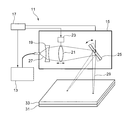
図1は第1構成例のアルミニウム接合体の製造方法に用いられるレーザ溶接装置の全体構成図である。
本構成のアルミニウム接合体の製造方法には、高エネルギービーム溶接を適用できる。高エネルギービーム溶接としては、レーザ溶接や電子ビーム溶接等が挙げられる。
Hereinafter, embodiments of the present invention will be described in detail with reference to the drawings.
FIG. 1 is an overall configuration diagram of a laser welding apparatus used in the method for manufacturing an aluminum joined body of the first configuration example.
High energy beam welding can be applied to the method of manufacturing the aluminum joined body of this configuration. Examples of the high energy beam welding include laser welding and electron beam welding.
レーザ溶接法には、焦点距離の長い集光光学系を用いて溶接するリモート溶接法がある。このリモート溶接法には、更にガルバノ・ミラーでレーザをスキャンするミラー・スキャン法と、ロボットの動作で焦点距離の長い溶接トーチを振って溶接するロボット・スキャン法がある。これらは、ワークに接近して溶接する通常のレーザ溶接と異なり、溶接トーチと溶接物との干渉に制限を受けることなく溶接できる利点がある。また、ミラー・スキャン法は、高速な多点溶接が可能となる。ロボット・スキャン法は、多点溶接の際のエアカット時間を大きく圧縮することがロボットの動作制御上困難となるが、リモート溶接を安価に実現できる利点がある。 Laser welding includes a remote welding method in which welding is performed using a condensing optical system having a long focal length. The remote welding method includes a mirror scanning method in which a laser is scanned with a galvanometer mirror and a robot scanning method in which a welding torch having a long focal length is shaken by a robot operation to perform welding. These are advantageous in that welding can be performed without being limited by interference between the welding torch and the welded object, unlike normal laser welding in which welding is performed close to the workpiece. In addition, the mirror scanning method enables high-speed multipoint welding. The robot scan method has an advantage that remote welding can be realized at a low cost, although it is difficult to control the operation of the robot by greatly compressing the air cut time during multi-point welding.
本構成のアルミニウム接合体の製造方法においては、ミラー・スキャン法によるレーザ溶接装置11を用いてスポット溶接を行うレーザスポット溶接の場合を説明する。なお、レーザビームに代えて、電子ビームを用いた電子ビーム溶接であってもよい。
In the manufacturing method of the aluminum joined body of this structure, the case of the laser spot welding which performs spot welding using the
ミラー・スキャン法によるレーザ溶接装置11は、レーザ発振器13と、レーザ走査ヘッド15と、これらを制御する制御装置17と、を有する。レーザ走査ヘッド15は、凹レンズ19、集光レンズ21、アクチュエータ23、及びミラー25等で構成される。
The
レーザ発振器13は、制御装置17からの指令に基づいてレーザ光27を出力する。そのレーザ光27のエネルギ出力値は、制御装置17からの指令により調整可能となる。レーザ発振器13から出力されたレーザ光27は、凹レンズ19で拡大され、集光レンズ21で集光された後、ミラー25で反射されて、高エネルギービーム(レーザビーム29)として溶接予定箇所に照射される。レーザビーム29としては、CO2レーザ、YAGレーザ、ファイバーレーザ、ディスクレーザ、半導体レーザ等の各種方式のものが使用可能である。
The
集光レンズ21は、アクチュエータ23により光軸方向に高速に移動可能に構成される。そして、レーザ光27の焦点距離は、集光レンズ21の光軸方向の移動により調整される。レーザ光27の焦点位置は、レーザ光27の照射面積(ビームスポット径)が最も小さくなり、レーザ光27のエネルギ密度が最も高くなる位置でもある。集光レンズ21のアクチュエータ23は、制御装置17に接続され、焦点距離が制御装置17により制御される。
The
したがって、レーザ溶接装置11は、レーザ走査ヘッド15のミラー25を傾斜させることにより、集光レンズ21から出力されるレーザ光27を、所望の焦点距離で高速且つ自在に照射できる。
Therefore, the
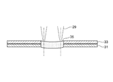
図2は図1に示したアルミニウム接合体をビーム照射方向で断面視した断面図である。
上記のレーザ溶接装置11を用いて重ね継手を形成するアルミニウム接合体の製造方法は、重ね継手形成工程と、ビーム溶接工程と、を有する。重ね継手形成工程は、第1アルミニウム部材31と、第1アルミニウム部材上に第1アルミニウム部材31よりも「導電率」の高い第2アルミニウム部材33を重ねて重ね継手を形成する。ここでは、導電率をIACS(international annealed copper standard)として表している。
FIG. 2 is a cross-sectional view of the aluminum joined body shown in FIG. 1 viewed in cross section in the beam irradiation direction.
The manufacturing method of the aluminum joined body which forms a lap joint using said
一般に、材料の導電率と熱伝導率との関係は、材料が金属である場合、電子数が多い程、電子熱伝導が大きくなることがウィーデマン・フランツの法則として知られている。導電率は、例えばアルミニウム(Al)、金(Au)、銅(Cu)、銀(Ag)の順で高くなる。熱伝導率も同様の順で高くなる。すなわち、導電率は熱伝達率に比例する。 In general, the relationship between the electrical conductivity and the thermal conductivity of a material is known as the Wiedemann-Franz law that when the material is a metal, the electron thermal conductivity increases as the number of electrons increases. The conductivity increases in the order of, for example, aluminum (Al), gold (Au), copper (Cu), and silver (Ag). The thermal conductivity increases in the same order. That is, the conductivity is proportional to the heat transfer coefficient.
導電率は、第1アルミニウム部材31の導電率をW1と、第2アルミニウム部材33の導電率をW2とした場合、例えばその差を7以上とすることが好ましい。
For example, when the conductivity of the
第1アルミニウム部材31及び第2アルミニウム部材33は、1000〜8000系のアルミニウム又はアルミニウム合金が使用可能である。機械的強度の点では5000系、6000系、7000系の合金が好適に用いられ、単層の材料だけでなく表面にアルミニウム(Al-Si系合金)のクラッド層を設けた構成としてもよい。
The
ビーム溶接工程は、下板の第1アルミニウム部材31に、上板の第2アルミニウム部材33を重ねた重ね継手のうち、導電率の高い第2アルミニウム部材側(上板側)からレーザビーム29を照射する。レーザビーム29は、重ね継手を貫通する溶融凝固部35を形成する。アルミニウム接合体の製造方法では、後述するように、上側に導電率の高い(すなわち熱伝導率の高い)材料を配置することで引張応力を低減できる。
In the beam welding process, the
溶接部におけるレーザビーム29のビーム径は0.3〜4.0mmとする。レーザビーム径は、入熱量やビームの走査方法によって適宜調整できる。レーザスポット溶接のビーム照射は、いわゆるキーホール型でもよいが、ビームの焦点を被溶接材の厚み方向にずらしてデフォーカスとしてもよい。また、ビームの走査方法は、後述するように、同心円状、渦巻き状等任意に設定することができる。
The beam diameter of the
図3はデフォーカスによるビーム照射部の模式図である。
レーザスポット溶接は、レーザビームをデフォーカスさせて行うものであってもよい。デフォーカスビーム37は、図1に示すレーザ溶接装置11の制御装置17により、例えばアクチュエータ23の駆動により、集光レンズ21を光軸に沿う方向に移動させて実施できる。
FIG. 3 is a schematic diagram of a beam irradiation unit by defocusing.
Laser spot welding may be performed by defocusing the laser beam. The
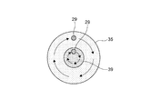
図4は同心円状のビーム走査によるビーム照射部の模式図である。
また、レーザスポット溶接は、レーザビーム29を同心円状に複数回走査させて行うものであってもよい。レーザビーム29の同心円状走査は、最初にレーザビーム29を照射した初期照射範囲39の外周部に同心円のパターンで連続して照射する。レーザビーム29の同心円状走査は、図1に示すレーザ溶接装置11の制御装置17によるミラー25の傾斜駆動で実施できる。
FIG. 4 is a schematic diagram of a beam irradiation unit by concentric beam scanning.
Laser spot welding may be performed by scanning the
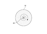
図5は螺旋状のビーム走査によるビーム照射部の模式図である。
更に、レーザスポット溶接は、レーザビーム29を螺旋状に複数回走査させて行うものであってもよい。レーザビーム29の螺旋状走査は、溶接部の中心部から外周側に向けて渦巻き状に連続して照射する。レーザビーム29の螺旋状走査は、前述の同心円走査と同様に、ミラー25の傾斜駆動により実施できる。
FIG. 5 is a schematic diagram of a beam irradiation unit by spiral beam scanning.
Further, laser spot welding may be performed by scanning the laser beam 29 a plurality of times in a spiral manner. The spiral scanning of the
次に、上記構成の作用を説明する。
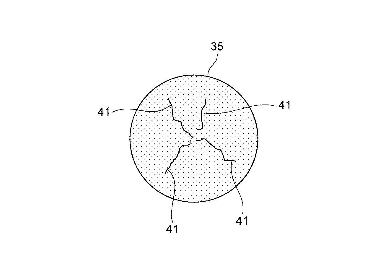
図6は割れを生じた溶融凝固部の模式図である。
アルミニウム接合体の製造方法において、溶接熱源は移動熱源であり、それにより溶接部は熱サイクルを受ける。溶接部は、熱源が近付くにつれて温度が急激に上昇し、最高到達温度に達してから冷却する。この場合に生じる溶接部の割れ41は、冷却特性に大きく依存する。冷却特性の主なものは、一般的に冷却速度と、冷却時間であるが、本発明では、これに加えて溶接物の導電率(熱伝導率)にも着目している。
Next, the operation of the above configuration will be described.
FIG. 6 is a schematic view of a melt-solidified portion in which a crack has occurred.
In the method of manufacturing an aluminum joined body, the welding heat source is a moving heat source, whereby the weld is subjected to a thermal cycle. As the heat source approaches the weld, the temperature rises rapidly, and cools after reaching the maximum temperature. The weld cracks 41 occurring in this case largely depend on the cooling characteristics. The main cooling characteristics are generally the cooling rate and the cooling time, but in the present invention, in addition to this, attention is also paid to the conductivity (thermal conductivity) of the weldment.
このアルミニウム接合体の製造方法によれば、第1アルミニウム部材上に、第1アルミニウム部材31よりも導電率の高い第2アルミニウム部材33を重ねて重ね継手を形成する。この状態で第2アルミニウム部材側からレーザビーム29を照射して、重ね継手を貫通する溶融凝固部35を形成する。この際、溶融池は、上板の第2アルミニウム部材33から下板の第1アルミニウム部材31にわたって形成される。この溶融池は、溶融部が凝固する際に、下板部分から徐々に凝固していくため、凝固割れが発生しにくくなる。
According to this aluminum joined body manufacturing method, the
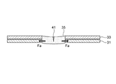
図7は上板部材の導電率が高い場合の溶融凝固部35の状態を断面図で示す説明図である。図中、Faは引張応力を示す。
上板の方が下板よりも導電率が高い場合、凝固が遅い下層部で発生した割れやひずみが、上層部に伝播しにくくなるため、割れ41が小さいか、生じなくなる。
FIG. 7 is an explanatory diagram showing a state of the melt-solidified
When the upper plate has a higher conductivity than the lower plate, cracks and strain generated in the lower layer portion, which is slowly solidified, are less likely to propagate to the upper layer portion, so that the
図8は下板部材の導電率が高い場合の溶融凝固部35の状態を断面図で示す説明図である。図中、Fbは引張応力を示す。
下板の方が上板よりも導電率が高い場合、凝固が早いため下層部で発生した割れやひずみが、凝固が遅い上層部に伝播しやすい。その結果、上層部の割れ41は図7に示す場合より大きくなる。また、それぞれの場合の引張応力は、Fa<Fbの関係となる。
FIG. 8 is an explanatory view showing the state of the melt-solidified
When the lower plate has a higher conductivity than the upper plate, solidification is faster, so that cracks and strains generated in the lower layer portion are likely to propagate to the upper layer portion where the solidification is slow. As a result, the
溶融凝固部35には、冷却後に収縮による引張応力が発生する。溶接部が溶接されると温度上昇により膨張し、その後の冷却により収縮が生じる。その際に、大きな引張応力が溶接部近傍から溶融凝固部35に作用する。本構成例によれば、溶融部が凝固する際に、下板部分から徐々に凝固が進むため、この引張応力が流動する溶融部に順次逃されて、溶融凝固部内に残留しにくくなる。
In the melted and solidified
また、このアルミニウム接合体の製造方法によれば、目的とする溶融凝固部35の中心に初期溶融池を形成している。レーザスポット溶接では、この溶融池を中心に、レーザビーム29を同心円状又は螺旋状に複数回走査させる。これにより、溶融凝固部35を形成するために必要な大きさの溶融池を、初期溶融池から拡大して形成できる。また、レーザビーム29は、任意方向への走査が可能となるので、真円以外の長円や楕円等の溶融凝固部35も形成できる。
In addition, according to this method of manufacturing an aluminum joined body, the initial molten pool is formed at the center of the target melted and solidified
また、アルミニウム接合体の製造方法によれば、レーザビーム29をデフォーカスさせて、目的とする溶融凝固部35の中心に初期溶融池を形成している。デフォーカスビーム37は、照射面積が大きいため、レーザビーム29を走査せずに、溶融凝固部35を形成するために必要な所要面積の溶融池を一度に作ることができる。なお、レーザビーム29のエネルギ密度が少なくなることにより照射深さは浅くなるが、溶融金属量は、デフォーカスを行わない時と同等に確保できる。また、所望の照射深さは、例えばビーム照射時間により制御が可能となる。
Further, according to the method of manufacturing the aluminum joined body, the
次に、上記のアルミニウム接合体の製造方法の変形例を説明する。
(変形例1)
第1アルミニウム部材31及び第2アルミニウム部材33を調質のみが異なる同一組成の熱処理型のアルミニウム合金とした。
Next, the modification of the manufacturing method of said aluminum joined body is demonstrated.
(Modification 1)
The
熱処理型のアルミニウム合金においては、溶体化処理により固溶していた元素が、時効処理により析出物として析出する。この析出物の状態により導電率の差が生じる。 In the heat-treatable aluminum alloy, the element that has been dissolved by the solution treatment is deposited as a precipitate by the aging treatment. A difference in conductivity occurs depending on the state of the precipitate.
そこで、同一材料である熱処理型のアルミニウム合金からなる板材を用い、それらに施す溶体化処理、時効処理の有無、又は溶体化処理、時効処理の加熱温度や保持時間等の熱処理条件を異ならせることにより、導電率に差を持たせる。その結果、同一のアルミニウム部材を用いた重ね継手であっても、固溶化処理や時効処理を選択的に施すことで、上板に導電率の高いアルミニウム部材を用い、下板に導電率の低いアルミニウム部材を用いた構成にでき、溶融凝固部35の割れ41を抑制することが可能となる。
Therefore, plate materials made of heat-treatable aluminum alloy, which is the same material, are used, and the heat treatment conditions such as solution treatment, presence / absence of aging treatment, or solution treatment, heating temperature and holding time of aging treatment are varied. Thus, the conductivity is made different. As a result, even if it is a lap joint using the same aluminum member, an aluminum member having high conductivity is used for the upper plate and a low conductivity is used for the lower plate by selectively performing solution treatment or aging treatment. It can be configured using an aluminum member, and the
(変形例2)
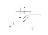
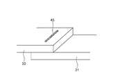
図9はレーザスポット溶接により接合された重ね継手の斜視図、図10はレーザ連続溶接により接合された重ね継手の斜視図である。
上記した溶融凝固部35は、図9に示すように、レーザスポット溶接で形成できるが、図10に示すように、レーザビーム29によるレーザ連続溶接で形成することもできる。
(Modification 2)
FIG. 9 is a perspective view of a lap joint joined by laser spot welding, and FIG. 10 is a perspective view of a lap joint joined by laser continuous welding.
The above-described melt-solidified
以上の通り、本発明は上記の実施形態に限定されるものではなく、実施形態の各構成を相互に組み合わせることや、明細書の記載、並びに周知の技術に基づいて、当業者が変更、応用することも本発明の予定するところであり、保護を求める範囲に含まれる。 As described above, the present invention is not limited to the above-described embodiments, and those skilled in the art can make changes and applications based on combinations of the configurations of the embodiments, descriptions in the specification, and well-known techniques. This is also the scope of the present invention, and is included in the scope for which protection is sought.
図11は6022材と3003材を上下入れ替えた場合の割れ長さの変化を表すグラフである。なお、以降に示す各棒グラフには、複数回の測定により求めた信頼限界も併せて示している。
(実験条件)
(a)板厚1.0mmの6022−T4材及び3003−0材を重ね溶接した。
(b)レーザ溶接は、レーザスポット径:3.5mm、レーザ出力:5.5kw、1秒間照射とした。
(c)レーザ装置は、YLS−6000−S4(IPG Photonics製)を用いた。
(d)導電率測定装置は、シグマテスタ(フェルスター社製)を用いた。
(e)レーザ照射側の割れ長さは、光学顕微鏡により測定した。
なお、(c)〜(e)については、第2、第3実施例も同様の条件で行った。
FIG. 11 is a graph showing changes in crack length when the 6022 material and the 3003 material are exchanged up and down. In addition, each bar graph shown below also shows the reliability limit obtained by a plurality of measurements.
(Experimental conditions)
(A) A 6022-T4 material and a 3003-0 material having a plate thickness of 1.0 mm were lap welded.
(B) Laser welding was performed with laser spot diameter: 3.5 mm, laser output: 5.5 kw, and irradiation for 1 second.
(C) As the laser device, YLS-6000-S4 (manufactured by IPG Photonics) was used.
(D) A sigma tester (manufactured by Forster Co., Ltd.) was used as the conductivity measuring device.
(E) The crack length on the laser irradiation side was measured with an optical microscope.
For (c) to (e), the second and third examples were performed under the same conditions.
(結果)
各試料の割れ長さを図11に示す。上板が3003材で下板が6022材の重ね継手よりも、上板が6022材で下板が3003材の重ね継手の方が割れ長さが長くなった。
(result)
The crack length of each sample is shown in FIG. The lap joint with the upper plate of 6022 material and the lower plate of 3003 material has a longer crack length than the lap joint with the upper plate of 3003 material and the lower plate of 6022 material.
(考察)
上板が3003材で下板が6022材の重ね継手よりも、上板が6022材で下板が3003材の継手の方が割れ長さが長くなったのは、上板と下板の熱伝導率の違いが原因であると考えられる。熱伝導率は、6022材が約45%IACSであり、3003材が約47%IACSである。つまり、6022材よりも3003材の方が熱伝導率が高い。下板の方が上板よりも熱伝導率が低い場合、下板部分における溶融池幅が上板部分よりも小さくなると考えられる。そのため、上板が3003材で下板が6022材の重ね継手は、溶融部が凝固する際に、下板部分から徐々に凝固していくため、凝固割れが発生しにくくなったと考えられる。
(Discussion)
Compared to the lap joint with 3003 material for the upper plate and 6022 material for the lower plate, the joint length with 6022 material for the upper plate and 3003 material for the lower plate has a longer crack length. The difference in conductivity is thought to be the cause. The thermal conductivity is about 45% IACS for the 6022 material and about 47% IACS for the 3003 material. That is, 3003 material has higher thermal conductivity than 6022 material. When the thermal conductivity of the lower plate is lower than that of the upper plate, the molten pool width in the lower plate portion is considered to be smaller than that of the upper plate portion. Therefore, it is considered that the lap joint with the upper plate made of 3003 and the lower plate made of 6022 is gradually solidified from the lower plate portion when the melted portion is solidified, so that solidification cracks are less likely to occur.
図12は6022材とAl−1wt%Fe材を上下入れ替えた場合の割れ長さの変化を表すグラフである。
(実験条件)
(a)板厚1.0mmの6022−T4材及びAl−1wt%Fe材を重ね溶接した。
(b)レーザ照射は、レーザスポット径:3.5mm、レーザ出力:5.5kw、1秒間照射とした。
FIG. 12 is a graph showing a change in crack length when the 6022 material and the Al-1 wt% Fe material are exchanged up and down.
(Experimental conditions)
(A) A 6022-T4 material having a thickness of 1.0 mm and an Al-1 wt% Fe material were lap welded.
(B) Laser irradiation was performed with laser spot diameter: 3.5 mm, laser output: 5.5 kw, and irradiation for 1 second.
(結果)
各試料の割れ長さを図12に示す。上板がAl−1wt%Fe材で下板が6022材の継手よりも、上板が6022材で下板がAl−1wt%Fe材の継手の方が割れ長さが長くなった。
(result)
The crack length of each sample is shown in FIG. The joint with the upper plate of the 6022 material and the lower plate of the Al-1 wt% Fe material has a longer crack length than the joint of the upper plate with the Al-1 wt% Fe material and the lower plate of the 6022 material.
(考察)
上板がAl−1wt%Fe材で下板が6022材の重ね継手よりも、上板が6022材で下板がAl−1wt%Fe材の重ね継手の方が割れ長さが長くなったのは、上板と下板の熱伝導率の違いが原因であると考えられる。熱伝導率は、6020材が約45%IACS、Al−1wt%Fe材が約58%IACSである。つまり、6022材よりもAl−1wt%Fe材の方が熱伝導率が高い。下板の方が上板よりも熱伝導率が低い場合、下板部分における溶融池幅が上板部分よりも小さくなると考えられる。そのため、上板がAl−1wt%Fe材で下板が6022材の重ね継手は、溶融部が凝固する際に、下板部分から徐々に凝固していくため、凝固割れが発生しにくくなったと考えられる。
(Discussion)
The lap joint with the upper plate of 6022 material and the lower plate of Al-1 wt% Fe material has a longer crack length than the lap joint with the upper plate of Al-1 wt% Fe material and the lower plate of 6022 material. Is considered to be caused by the difference in thermal conductivity between the upper and lower plates. The thermal conductivity of the 6020 material is about 45% IACS, and the Al-1 wt% Fe material is about 58% IACS. That is, the Al-1 wt% Fe material has higher thermal conductivity than the 6022 material. When the thermal conductivity of the lower plate is lower than that of the upper plate, the molten pool width in the lower plate portion is considered to be smaller than that of the upper plate portion. Therefore, the lap joint with the upper plate made of Al-1 wt% Fe and the lower plate made of 6022 gradually solidifies from the lower plate portion when the melted portion solidifies, so that solidification cracking is less likely to occur. Conceivable.
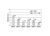
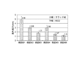
図13は6022材を上板、クラッド材を下板とした場合の割れ長さを表すグラフ、図14はクラッド材を上板、6022材を下板とした場合の割れ長さを表すグラフである。
(実験条件)
(a)板厚1.0mmの6022−T4材及びクラッド材を重ね溶接した。使用したクラッド材の一覧を表1に示す。クラッド材は、表1に示す心材組成を有し、残部がFe及び不可避不純物である。
(b)レーザ照射は、レーザスポット径:3.5mm、レーザ出力:505kw、1秒間照射とした。
FIG. 13 is a graph showing the crack length when the 6022 material is the upper plate and the clad material is the lower plate, and FIG. 14 is a graph showing the crack length when the clad material is the upper plate and the 6022 material is the lower plate. is there.
(Experimental conditions)
(A) A 6022-T4 material having a plate thickness of 1.0 mm and a clad material were lap welded. Table 1 shows a list of the clad materials used. The clad material has a core material composition shown in Table 1, with the balance being Fe and inevitable impurities.
(B) Laser irradiation was performed with laser spot diameter: 3.5 mm, laser output: 505 kw, and irradiation for 1 second.
(結果)
各試料の割れ長さを図13、図14に示す。クラッド材皮材のSi濃度が高くなるほど割れ長さが短くなった。また、図13に示す上板が6022材で下板がクラッド材の重ね継手よりも、図14に示す上板がクラッド材で下板が6022材の重ね継手の方が割れ長さが長くなった。
(result)
The crack length of each sample is shown in FIGS. The crack length shortened as the Si concentration of the cladding material skin increased. In addition, the lap joint of the upper plate shown in FIG. 14 with the clad material and the lower plate of 6022 material has a longer crack length than the lap joint with the upper plate of 6022 material and the lower plate shown in FIG. It was.
(考察)
上板が6022材で下板がクラッド材の重ね継手よりも、上板がクラッド材で下板が6022材の重ね継手の方が割れ長さが長くなったのは、上板と下板の熱伝導率の違いが原因であると考えられる。熱伝導率は、クラッド材が40〜45%IACS、6022材が約45%IACSである。つまり、クラッド材よりも6022材の方が熱伝導率が高い。下板の方が上板よりも熱伝導率が低い場合、下板部分における溶融池幅が上板部分よりも小さくなると考えられる。そのため、上板が6022材で下板がクラッド材の重ね継手は、溶融部が凝固する際に、下板部分から徐々に凝固していくため、凝固割れが発生しにくくなったと考えられる。
(Discussion)
The lap joint where the upper plate is clad material and the lower plate is 6022 material has a longer crack length than the lap joint where the upper plate is 6022 material and the lower plate is clad material. It is thought that this is due to the difference in thermal conductivity. The thermal conductivity is 40 to 45% IACS for the clad material and about 45% IACS for the 6022 material. That is, 6022 material has higher thermal conductivity than clad material. When the thermal conductivity of the lower plate is lower than that of the upper plate, the molten pool width in the lower plate portion is considered to be smaller than that of the upper plate portion. Therefore, it is considered that the lap joint in which the upper plate is 6022 material and the lower plate is clad material is gradually solidified from the lower plate portion when the melted portion is solidified, so that solidification cracks are less likely to occur.
以上の通り、本明細書には次の事項が開示されている。
(1) 第1アルミニウム部材と、前記第1アルミニウム部材上に前記第1アルミニウム部材よりも導電率の高い第2アルミニウム部材を重ねて重ね継手を形成する工程と、前記第2アルミニウム部材側から高エネルギービームを照射して、前記重ね継手を貫通する溶融凝固部を形成するビーム溶接工程と、を有するアルミニウム接合体の製造方法。
このアルミニウム接合体の製造方法によれば、第1アルミニウム部材上に、第1アルミニウム部材よりも導電率の高い第2アルミニウム部材を重ねて重ね継手を形成する。この状態で第2アルミニウム部材側から高エネルギービームを照射して、重ね継手を貫通する溶融凝固部を形成する。この際、溶融池は、上板の第2アルミニウム部材から下板の第1アルミニウム部材にわたって連続して形成される。この溶融池は、熱伝導率が低い下板の第1アルミニウム部材の方が、上板の第2アルミニウム部材よりも溶融池幅が小さくなると考えられ、その結果、溶融部が凝固する際に、下板部分から徐々に凝固して、凝固割れが発生しにくくなる。
As described above, the following items are disclosed in this specification.
(1) A step of forming a lap joint by stacking a first aluminum member, a second aluminum member having a higher conductivity than the first aluminum member on the first aluminum member, and a height from the second aluminum member side. A beam welding step of irradiating an energy beam to form a melt-solidified portion penetrating the lap joint.
According to this method for manufacturing an aluminum joined body, a lap joint is formed by stacking a second aluminum member having a higher conductivity than the first aluminum member on the first aluminum member. In this state, a high energy beam is irradiated from the second aluminum member side to form a melt-solidified portion that penetrates the lap joint. At this time, the molten pool is continuously formed from the second aluminum member of the upper plate to the first aluminum member of the lower plate. In this molten pool, the first aluminum member of the lower plate having a low thermal conductivity is considered to have a smaller molten pool width than the second aluminum member of the upper plate, and as a result, when the molten part solidifies, It gradually solidifies from the lower plate part and solidification cracks are less likely to occur.
(2) 前記溶融凝固部を、前記高エネルギービームによるスポット溶接で形成する(1)のアルミニウム接合体の製造方法。
このアルミニウム接合体の製造方法によれば、高エネルギービームにより溶融凝固部が形成される。高エネルギービームは、高エネルギ密度の集中熱源であるので、加工時に第2アルミニウム部材に与える熱影響を小さくでき、溶融凝固部近傍の変形も小さくできる。よって、小型且つ精密な重ね継手の形成が可能となる。
(2) The method for manufacturing an aluminum joined body according to (1), wherein the melt-solidified portion is formed by spot welding with the high-energy beam.
According to this method of manufacturing an aluminum joined body, a melt-solidified portion is formed by a high energy beam. Since the high energy beam is a concentrated heat source with a high energy density, the thermal effect on the second aluminum member during processing can be reduced, and deformation near the melt-solidified portion can also be reduced. Therefore, a small and precise lap joint can be formed.
(3) 前記スポット溶接は、前記高エネルギービームを同心円状又は螺旋状に複数回走査させて行う(2)のアルミニウム接合体の製造方法。
このアルミニウム接合体の製造方法によれば、目的とする溶融凝固部の中心に初期溶融池を作る。スポット溶接は、この溶融池を中心に、高エネルギービームを同心円状又は螺旋状に複数回走査させることにより、溶融凝固部を形成するために必要な所要面積の溶融池を、初期溶融池を拡げて作ることができる。また、高エネルギービームは、任意方向への走査が可能となるので、真円以外の長円や楕円等の溶融凝固部を作ることが可能となる。
(3) The method for manufacturing an aluminum joined body according to (2), wherein the spot welding is performed by scanning the high energy beam a plurality of times concentrically or spirally.
According to this method of manufacturing an aluminum joined body, an initial molten pool is formed at the center of the target melted and solidified portion. In spot welding, a high energy beam is scanned concentrically or spirally around this molten pool multiple times to expand the molten pool of the required area to form the molten solidified zone. Can be made. Further, since the high energy beam can be scanned in an arbitrary direction, it is possible to form a melted and solidified portion such as an ellipse other than a perfect circle or an ellipse.
(4) 前記スポット溶接は、前記高エネルギービームをデフォーカスさせて行う(2)のアルミニウム接合体の製造方法。
このアルミニウム接合体の製造方法によれば、高エネルギービームをデフォーカスさせて、目的とする溶融凝固部の中心に初期溶融池を形成する。デフォーカスによる高エネルギービームは、照射面積を増減でき、これにより、スポット溶接は、高エネルギービームを走査せずに、溶融凝固部を形成するために必要な大きさの溶融池を一度に作ることができる。
(4) The method for manufacturing an aluminum joined body according to (2), wherein the spot welding is performed by defocusing the high energy beam.
According to this method of manufacturing an aluminum joined body, an initial molten pool is formed at the center of a target melt-solidified portion by defocusing a high energy beam. The high-energy beam by defocusing can increase or decrease the irradiation area, so that spot welding can create a molten pool of the size required to form a molten solidified part at once without scanning the high-energy beam. Can do.
(5) 前記溶融凝固部を、前記高エネルギービームによる連続溶接で形成する(1)のアルミニウム接合体の製造方法。
このアルミニウム接合体の製造方法によれば、第2アルミニウム部材に照射される高エネルギービームが、直線的に連続走査される。これにより、割れのない連続した溶融凝固部を形成できる。
(5) The method for manufacturing an aluminum joined body according to (1), wherein the melt-solidified portion is formed by continuous welding using the high-energy beam.
According to this method for manufacturing an aluminum joined body, the high energy beam applied to the second aluminum member is continuously scanned linearly. Thereby, the continuous melt-solidified part without a crack can be formed.
29 レーザビーム(高エネルギービーム)
31 第1アルミニウム部材
33 第2アルミニウム部材
35 溶融凝固部
29 Laser beam (high energy beam)
31
Claims (5)
前記第2アルミニウム部材側から高エネルギービームを照射して、前記重ね継手を貫通する溶融凝固部を形成するビーム溶接工程と、
を有するアルミニウム接合体の製造方法。 Forming a lap joint by stacking a first aluminum member and a second aluminum member having a higher conductivity than the first aluminum member on the first aluminum member;
A beam welding step of irradiating a high energy beam from the second aluminum member side to form a melt-solidified portion penetrating the lap joint;
The manufacturing method of the aluminum joined body which has this.
Priority Applications (3)
| Application Number | Priority Date | Filing Date | Title |
|---|---|---|---|
| JP2016180001A JP6719348B2 (en) | 2016-09-14 | 2016-09-14 | Method for manufacturing aluminum joined body |
| CN201710463783.0A CN107824964B (en) | 2016-09-14 | 2017-06-19 | The manufacturing method of aluminium conjugant |
| US15/674,630 US20180071866A1 (en) | 2016-09-14 | 2017-08-11 | Method for producing aluminum joined body |
Applications Claiming Priority (1)
| Application Number | Priority Date | Filing Date | Title |
|---|---|---|---|
| JP2016180001A JP6719348B2 (en) | 2016-09-14 | 2016-09-14 | Method for manufacturing aluminum joined body |
Publications (2)
| Publication Number | Publication Date |
|---|---|
| JP2018043273A true JP2018043273A (en) | 2018-03-22 |
| JP6719348B2 JP6719348B2 (en) | 2020-07-08 |
Family
ID=61559082
Family Applications (1)
| Application Number | Title | Priority Date | Filing Date |
|---|---|---|---|
| JP2016180001A Expired - Fee Related JP6719348B2 (en) | 2016-09-14 | 2016-09-14 | Method for manufacturing aluminum joined body |
Country Status (3)
| Country | Link |
|---|---|
| US (1) | US20180071866A1 (en) |
| JP (1) | JP6719348B2 (en) |
| CN (1) | CN107824964B (en) |
Cited By (1)
| Publication number | Priority date | Publication date | Assignee | Title |
|---|---|---|---|---|
| JP2020062682A (en) * | 2018-10-19 | 2020-04-23 | フタバ産業株式会社 | Welding method |
Families Citing this family (7)
| Publication number | Priority date | Publication date | Assignee | Title |
|---|---|---|---|---|
| JP7063083B2 (en) * | 2018-04-25 | 2022-05-09 | トヨタ自動車株式会社 | Laser welding method |
| JP7081324B2 (en) * | 2018-06-19 | 2022-06-07 | トヨタ自動車株式会社 | Laser welding method and welded structure |
| CN115609151B (en) * | 2018-08-30 | 2026-01-16 | 罗姆股份有限公司 | Semiconductor devices |
| JP6898287B2 (en) * | 2018-10-19 | 2021-07-07 | フタバ産業株式会社 | Welding method |
| CN109967869A (en) * | 2019-04-08 | 2019-07-05 | 上海工程技术大学 | A kind of pulse laser stitch welding process method of 6061 aluminum alloy sheet |
| CN113523568B (en) * | 2020-04-20 | 2024-04-12 | 中国科学院上海光学精密机械研究所 | Aluminum or aluminum alloy lap joint laser spot welding method |
| US11471975B1 (en) * | 2021-06-03 | 2022-10-18 | Corelase Oy | Spiral laser welding methods for joining metal |
Citations (8)
| Publication number | Priority date | Publication date | Assignee | Title |
|---|---|---|---|---|
| JPH06126476A (en) * | 1992-10-13 | 1994-05-10 | Nissan Motor Co Ltd | Laser welding method for aluminum alloy |
| JPH08332582A (en) * | 1995-06-05 | 1996-12-17 | Toshiba Corp | Laser welding method |
| JPH0910973A (en) * | 1995-06-28 | 1997-01-14 | Isuzu Motors Ltd | Laser welding method |
| JP2007222937A (en) * | 2006-02-27 | 2007-09-06 | Toyota Motor Corp | Laser bonding method |
| JP2013513486A (en) * | 2009-12-11 | 2013-04-22 | ダイムラー・アクチェンゲゼルシャフト | Welding method of two metal constituent members and joint structure having two metal constituent members |
| JP2015025147A (en) * | 2013-07-24 | 2015-02-05 | 株式会社Uacj | Aluminum alloy bus bar |
| JP2015147236A (en) * | 2014-02-06 | 2015-08-20 | 株式会社神戸製鋼所 | Joined member for high energy beam welding and method of manufacturing joined body |
| JP2017128758A (en) * | 2016-01-19 | 2017-07-27 | 株式会社Uacj | Aluminum alloy plate for conductive member, method for producing the same, and electrical connection component |
Family Cites Families (8)
| Publication number | Priority date | Publication date | Assignee | Title |
|---|---|---|---|---|
| WO2006016441A1 (en) * | 2004-08-09 | 2006-02-16 | Nec Corporation | Method for welding thin plates of different metal, joined body of thin plates of different metal, electric device, and electric device assembly |
| CN101439451A (en) * | 2007-11-22 | 2009-05-27 | 苏州达方电子有限公司 | Welding device and welding method |
| JP5527526B2 (en) * | 2010-02-24 | 2014-06-18 | マツダ株式会社 | Laser welding method |
| US9839971B2 (en) * | 2013-09-20 | 2017-12-12 | GM Global Technology Operations LLC | Resistance spot welding steel and aluminum workpieces with hot welding electrode at aluminum workpiece |
| WO2015104781A1 (en) * | 2014-01-10 | 2015-07-16 | パナソニックIpマネジメント株式会社 | Laser welding method and laser welding device |
| JP6032236B2 (en) * | 2014-04-08 | 2016-11-24 | トヨタ自動車株式会社 | Laser welding method and welded structure |
| JP6024707B2 (en) * | 2014-05-22 | 2016-11-16 | トヨタ自動車株式会社 | Laser welding method |
| CN104985325B (en) * | 2015-08-12 | 2016-05-25 | 辽宁工业大学 | A kind of red copper and fine aluminium sheet material laser stitch welding device and method |
-
2016
- 2016-09-14 JP JP2016180001A patent/JP6719348B2/en not_active Expired - Fee Related
-
2017
- 2017-06-19 CN CN201710463783.0A patent/CN107824964B/en not_active Expired - Fee Related
- 2017-08-11 US US15/674,630 patent/US20180071866A1/en not_active Abandoned
Patent Citations (8)
| Publication number | Priority date | Publication date | Assignee | Title |
|---|---|---|---|---|
| JPH06126476A (en) * | 1992-10-13 | 1994-05-10 | Nissan Motor Co Ltd | Laser welding method for aluminum alloy |
| JPH08332582A (en) * | 1995-06-05 | 1996-12-17 | Toshiba Corp | Laser welding method |
| JPH0910973A (en) * | 1995-06-28 | 1997-01-14 | Isuzu Motors Ltd | Laser welding method |
| JP2007222937A (en) * | 2006-02-27 | 2007-09-06 | Toyota Motor Corp | Laser bonding method |
| JP2013513486A (en) * | 2009-12-11 | 2013-04-22 | ダイムラー・アクチェンゲゼルシャフト | Welding method of two metal constituent members and joint structure having two metal constituent members |
| JP2015025147A (en) * | 2013-07-24 | 2015-02-05 | 株式会社Uacj | Aluminum alloy bus bar |
| JP2015147236A (en) * | 2014-02-06 | 2015-08-20 | 株式会社神戸製鋼所 | Joined member for high energy beam welding and method of manufacturing joined body |
| JP2017128758A (en) * | 2016-01-19 | 2017-07-27 | 株式会社Uacj | Aluminum alloy plate for conductive member, method for producing the same, and electrical connection component |
Cited By (1)
| Publication number | Priority date | Publication date | Assignee | Title |
|---|---|---|---|---|
| JP2020062682A (en) * | 2018-10-19 | 2020-04-23 | フタバ産業株式会社 | Welding method |
Also Published As
| Publication number | Publication date |
|---|---|
| JP6719348B2 (en) | 2020-07-08 |
| CN107824964A (en) | 2018-03-23 |
| CN107824964B (en) | 2019-10-01 |
| US20180071866A1 (en) | 2018-03-15 |
Similar Documents
| Publication | Publication Date | Title |
|---|---|---|
| JP6719348B2 (en) | Method for manufacturing aluminum joined body | |
| Dada et al. | Recent advances in joining technologies of aluminum alloys: a review | |
| JP4573108B2 (en) | Welding method | |
| EP1446256A1 (en) | Process for avoiding cracking in welding | |
| WO2015159503A1 (en) | Joined body of dissimilar metals | |
| KR102328270B1 (en) | Resistance spot welding joint of aluminum material, and resistance spot welding method of aluminum material | |
| CN113664218A (en) | Composite manufacturing method of ultra-large metal structure | |
| JP2020093272A (en) | Laser welding method | |
| CN110666349A (en) | Laser welding method | |
| JP2019217524A (en) | Laser weld method and weld structure | |
| JP2011005499A (en) | Method for laser butt-welding aluminum member and copper member | |
| CN117259978A (en) | Ultrafast laser welding systems and methods for sapphire and semiconductors | |
| WO2023157809A1 (en) | Laser welding method | |
| Murzin et al. | Features of laser welding of sandwich composite metal-polymer materials | |
| CN115768586B (en) | Method for manufacturing dissimilar material joined structure | |
| CN118808912A (en) | A method and system for laser spot welding of dissimilar materials | |
| Vollertsen | Developments and trends in laser welding of sheet metal | |
| Kim et al. | Welding of AZ31B magnesium alloy by YAG laser/TIG arc hybrid welding process | |
| JP3082468B2 (en) | Laser welding method of aluminum alloy | |
| JP2018108602A (en) | Overlap laser spot weld joint and manufacturing method for the weld joint | |
| EA028399B1 (en) | Method for laser welding of parts made of dissimilar metals | |
| Bárta et al. | Electron Beam Welding of 2099-T83 aluminium-lithium alloy thick plates | |
| JP6408824B2 (en) | Metal clad welding material and method for producing metal clad welding material | |
| JP7747678B2 (en) | Manufacturing method of components | |
| JP6947669B2 (en) | Laser welding method |
Legal Events
| Date | Code | Title | Description |
|---|---|---|---|
| A621 | Written request for application examination |
Free format text: JAPANESE INTERMEDIATE CODE: A621 Effective date: 20181203 |
|
| A977 | Report on retrieval |
Free format text: JAPANESE INTERMEDIATE CODE: A971007 Effective date: 20191010 |
|
| A131 | Notification of reasons for refusal |
Free format text: JAPANESE INTERMEDIATE CODE: A131 Effective date: 20191112 |
|
| TRDD | Decision of grant or rejection written | ||
| A01 | Written decision to grant a patent or to grant a registration (utility model) |
Free format text: JAPANESE INTERMEDIATE CODE: A01 Effective date: 20200602 |
|
| A61 | First payment of annual fees (during grant procedure) |
Free format text: JAPANESE INTERMEDIATE CODE: A61 Effective date: 20200616 |
|
| R150 | Certificate of patent or registration of utility model |
Ref document number: 6719348 Country of ref document: JP Free format text: JAPANESE INTERMEDIATE CODE: R150 |
|
| LAPS | Cancellation because of no payment of annual fees |