JP2018062425A - A yarn splicing device for a work unit of a textile machine for manufacturing a chewy package - Google Patents
A yarn splicing device for a work unit of a textile machine for manufacturing a chewy package Download PDFInfo
- Publication number
- JP2018062425A JP2018062425A JP2017199325A JP2017199325A JP2018062425A JP 2018062425 A JP2018062425 A JP 2018062425A JP 2017199325 A JP2017199325 A JP 2017199325A JP 2017199325 A JP2017199325 A JP 2017199325A JP 2018062425 A JP2018062425 A JP 2018062425A
- Authority
- JP
- Japan
- Prior art keywords
- yarn
- splicing
- thread
- passage
- splicing device
- Prior art date
- Legal status (The legal status is an assumption and is not a legal conclusion. Google has not performed a legal analysis and makes no representation as to the accuracy of the status listed.)
- Pending
Links
- 238000004519 manufacturing process Methods 0.000 title claims abstract description 9
- 239000004753 textile Substances 0.000 title claims abstract description 6
- 239000002184 metal Substances 0.000 claims description 10
- 230000004308 accommodation Effects 0.000 claims description 4
- 230000002093 peripheral effect Effects 0.000 claims description 3
- 238000004804 winding Methods 0.000 description 21
- 238000000034 method Methods 0.000 description 16
- 238000005520 cutting process Methods 0.000 description 15
- 238000009987 spinning Methods 0.000 description 5
- 238000003780 insertion Methods 0.000 description 3
- 230000037431 insertion Effects 0.000 description 3
- 238000002360 preparation method Methods 0.000 description 3
- 238000003860 storage Methods 0.000 description 3
- 230000008878 coupling Effects 0.000 description 2
- 238000010168 coupling process Methods 0.000 description 2
- 238000005859 coupling reaction Methods 0.000 description 2
- 230000002950 deficient Effects 0.000 description 2
- 239000000835 fiber Substances 0.000 description 2
- 238000007664 blowing Methods 0.000 description 1
- 239000000470 constituent Substances 0.000 description 1
- 238000010276 construction Methods 0.000 description 1
- 230000007547 defect Effects 0.000 description 1
- 230000001419 dependent effect Effects 0.000 description 1
- 239000000463 material Substances 0.000 description 1
- 239000012188 paraffin wax Substances 0.000 description 1
- 230000000717 retained effect Effects 0.000 description 1
- 230000002441 reversible effect Effects 0.000 description 1
- 238000007378 ring spinning Methods 0.000 description 1
Images

Classifications
-
- B—PERFORMING OPERATIONS; TRANSPORTING
- B65—CONVEYING; PACKING; STORING; HANDLING THIN OR FILAMENTARY MATERIAL
- B65H—HANDLING THIN OR FILAMENTARY MATERIAL, e.g. SHEETS, WEBS, CABLES
- B65H69/00—Methods of, or devices for, interconnecting successive lengths of material; Knot-tying devices ;Control of the correct working of the interconnecting device
- B65H69/06—Methods of, or devices for, interconnecting successive lengths of material; Knot-tying devices ;Control of the correct working of the interconnecting device by splicing
- B65H69/061—Methods of, or devices for, interconnecting successive lengths of material; Knot-tying devices ;Control of the correct working of the interconnecting device by splicing using pneumatic means
-
- B—PERFORMING OPERATIONS; TRANSPORTING
- B65—CONVEYING; PACKING; STORING; HANDLING THIN OR FILAMENTARY MATERIAL
- B65H—HANDLING THIN OR FILAMENTARY MATERIAL, e.g. SHEETS, WEBS, CABLES
- B65H2701/00—Handled material; Storage means
- B65H2701/30—Handled filamentary material
- B65H2701/31—Textiles threads or artificial strands of filaments
Landscapes
- Spinning Or Twisting Of Yarns (AREA)
- Guides For Winding Or Rewinding, Or Guides For Filamentary Materials (AREA)
Abstract
Description
本発明は、綾巻きパッケージを製造する繊維機械の作業ユニット用の糸スプライシング装置であって、圧縮空気を供給可能なスプライシング通路を有する、空気分配体に固定可能なスプライシング角柱体(Spleisspisma)と、スプライシング角柱体に対して間隔を置いて配置されている、制限されて回動可能に支承された糸寄せ器とを備える、糸スプライシング装置に関する。 The present invention relates to a yarn splicing device for a working unit of a textile machine for manufacturing a spiral wound package, having a splicing passage capable of supplying compressed air, and a splicing prism (Spleisspisma) that can be fixed to an air distributor; The present invention relates to a yarn splicing device including a limited and pivotally supported yarn feeder arranged at a distance from a splicing prism.
このような糸スプライシング装置は、特に自動綾巻きワインダの作業ユニットにおいて、例えば糸切れ後またはコントロール下の糸クリアリング切断後のような巻取り中断後に、本来の糸とほぼ同じ接合箇所が得られるように、2つの糸端部を空気力によって再び接合させようとするときに使用される。 Such a yarn splicing device, particularly in a work unit of an automatic traverse winder, can obtain approximately the same joint location as the original yarn after winding interruption, for example after yarn breakage or after controlled yarn clearing cut. Thus, it is used when trying to rejoin two yarn ends by aerodynamic force.
このような糸スプライシング装置は、そのために、スプライシング通路に空気を供給可能であるスプライシング角柱体を有しているだけではなく、両方の糸端部を、これらの糸端部が空気力によってスプライシングされる前に、正確に所定の長さに切断し、適正に準備し、かつ規定通りにスプライシング角柱体のスプライシング通路内に位置決めすることを可能にする装置も備えている。すなわち、このような糸スプライシング装置は、糸クランプ装置、糸切断装置および糸寄せ器を備えていて、空気を供給可能な保持兼解撚管を有している。 For this purpose, such a yarn splicing device not only has a splicing prism that can supply air to the splicing passage, but also both yarn ends are spliced by aerodynamic forces. It is also provided with a device that allows it to be precisely cut to a predetermined length, properly prepared and positioned in the splicing passage of the splicing prism as prescribed. That is, such a yarn splicing device includes a yarn clamping device, a yarn cutting device, and a yarn feeder, and has a holding and untwisting tube capable of supplying air.
例えば、独国特許出願公開第10224080号明細書(DE 102 24 080 A1)には、圧縮空気を供給可能なスプライシング角柱体と、必要な場合に同様に圧縮空気を供給可能な2つの保持兼解撚管とを有する糸スプライシング装置が記載されている。このとき保持兼解撚管は、通常のように、スプライシング角柱体のスプライシング通路の出口に対して幾分か間隔を置いてかつ側方にずらされて配置されている。このような公知の糸スプライシング装置では、これに所属の糸クランプ装置および糸切断装置の駆動は、差込みカップリングを介して該当する作業ユニットの駆動装置に接続されているカム板駆動装置を介して行われる。これに対して、旋回軸線を中心に可動に支承されている糸寄せ器は、さらに作業ユニットコンピュータに接続されている個別駆動装置(好ましくはステップモータ)によって駆動される。 For example, DE 102 24 080 A1 (DE 102 24 080 A1) describes a splicing prism that can be supplied with compressed air and two holding and holding solutions that can also be supplied with compressed air if necessary. A yarn splicing device having a twisted tube is described. At this time, the holding and untwisting tube is arranged at a distance from the outlet of the splicing passage of the splicing prism and is shifted laterally as usual. In such a known yarn splicing device, the drive of the associated yarn clamping device and yarn cutting device is via a cam plate drive device connected to the drive device of the corresponding work unit via an insertion coupling. Done. On the other hand, the yarn feeder which is supported movably around the turning axis is further driven by an individual drive device (preferably a step motor) connected to the work unit computer.
このとき糸寄せ器は、第1の形態において、2つのアームを有しており、これらのアームは、糸寄せ器の作動時に上方から上糸および下糸の糸端部の糸ストランドに対して旋回し、その際にそれぞれが下方を向いた糸ループを形成するように、旋回軸に配置されている。すなわち、糸寄せ器の、下方へ旋回する両アームは、糸ループを形成しており、この糸ループによって、準備された両糸端部は、保持兼解撚管から引き出されて、適正に重畳されてスプライシング角柱体のスプライシング通路内に位置決めされる。 At this time, in the first mode, the yarn feeder has two arms, and these arms are against the yarn strands at the ends of the upper yarn and the lower yarn from above when the yarn feeder is operated. It is arranged on the swivel shaft so as to form a yarn loop that turns downward and each of which turns downward. In other words, both arms that rotate downward of the yarn feeder form a yarn loop, and by this yarn loop, the prepared yarn ends are pulled out from the holding and untwisting tube and properly overlapped. And positioned in the splicing passage of the splicing prism.
1つの択一的な形態において、糸寄せ器は、回転羽根の形式で構成されている。このとき糸寄せ器の両アームは、糸寄せ器の旋回軸に対して直交して配置されていて、保持兼解撚管内に配置された後続のスプライシングすべき糸端部の糸ストランドにそれぞれ横方向から作用するように旋回する。ここでも、発生して側方に延びる糸ループは、準備された両糸端部が、保持兼解撚管から引き出され、適正に重畳されてスプライシング角柱体のスプライシング通路内に位置決めされるように働く。 In one alternative form, the yarn catcher is configured in the form of a rotary vane. At this time, both arms of the yarn gathering device are arranged orthogonally to the swivel axis of the yarn gathering device, and are respectively lateral to the yarn strand at the yarn end portion to be spliced in the holding and untwisting tube. Turn to act from the direction. Here again, the yarn loops that are generated and extend laterally are such that both prepared yarn ends are pulled out of the holding and untwisting tube and properly overlapped and positioned within the splicing passage of the splicing prism. work.
糸寄せ器が回転羽根の形式で構成されている糸スプライシング装置は、独国特許出願公開第4420979号明細書(DE 44 20 979 A1)にも記載されている。このような公知の糸スプライシング装置において、スプライシング角柱体と空気分配体との間に、回転羽根が制限されて回転可能に支承されており、この回転羽根は、相応の駆動構造部を介して様々な機能位置へ旋回可能である。すなわち、このような公知の糸スプライシング装置において、糸継ぎ工程中に糸寄せ器によってまず側方に延びる糸ループが形成されて、このとき回転羽根を、糸端部の準備を最適化するために、例えば、糸端部がこれに所属の保持兼解撚管の開口の上方のほぼ中心に配置される糸調整位置に位置決めすることができる。
A yarn splicing device in which the yarn catcher is configured in the form of a rotary blade is also described in
このような公知の糸スプライシング装置も、通常のように、後続のスプライシング工程のために準備すべき糸を処理するために、糸クランプ装置および糸切断装置を備えていて、このとき糸切断装置は、好ましくは保持兼解撚管の開口の直ぐ近くにそれぞれ配置されている。 Such a known yarn splicing device is also provided with a yarn clamping device and a yarn cutting device for processing the yarn to be prepared for the subsequent splicing process as usual. Preferably, they are respectively arranged in the immediate vicinity of the opening of the holding and untwisting tube.
上述の糸スプライシング装置は、実地においてそれ自体良好であると認められているが、かけられた糸撚りの一部がスプライシング工程中に糸継ぎ箇所に入り込まずに消失してしまうおそれが常にある、という欠点を有している。すなわち、このような公知の糸スプライシング装置には、スプライシング角柱体のスプライシング通路内で糸端部にかけられた糸撚りの一部が、糸端部の、スプライシング角柱体のスプライシング通路の両側において露出しかつ糸ループとしてそれぞれ形成された部分の領域に入り、ひいては本来の糸継ぎ領域が消失してしまう、というおそれが常にあった。 The above-mentioned yarn splicing device is recognized as being good in practice, but there is always a possibility that a part of the applied yarn twist may be lost without entering the spliced part during the splicing process. Has the disadvantages. That is, in such a known yarn splicing device, a part of the yarn twist applied to the yarn end in the splicing passage of the splicing prism is exposed on both sides of the splicing passage of the splicing prism. In addition, there has always been a risk that the region of the part formed as a yarn loop may be entered, and the original spliced region may disappear.
上記形式の糸スプライシング装置を出発点として、本発明の根底を成す課題は、糸スプライシング装置を改良して、スプライシング工程中に空気力によってかけられた糸撚りがスプライシング角柱体のスプライシング通路の領域で保持され、これにより糸継ぎ箇所へ移されて、それぞれ1つの糸ループを形成する糸端部へ少なくとも部分的にも逃げられないことを保証するようにすることである。 Starting from a yarn splicing device of the above type, the problem underlying the present invention is to improve the yarn splicing device so that the yarn twist applied by aerodynamic force during the splicing process is in the region of the splicing passage of the splicing prism. It is to be held and thereby transferred to the yarn splice point to ensure that it does not escape at least partly to the yarn ends, each forming one yarn loop.
この課題は、本発明によれば、スプライシング角柱体の領域に、上糸および下糸の糸端部を収容する糸ガイド溝が配置されていて、かつスプライシング角柱体のスプライシング通路の出口側に、保持兼解撚管用の収容孔を有する、漏斗状に形成された出口開口がそれぞれ1つ配置されている糸スプライシング装置によって解決される。 According to the present invention, according to the present invention, the yarn guide groove for accommodating the yarn ends of the upper thread and the lower thread is disposed in the region of the splicing prism body, and on the outlet side of the splicing passage of the splicing prism body, This is solved by a yarn splicing device in which one outlet opening formed in a funnel shape having a holding hole for a holding and untwisting tube is arranged.
本発明の有利な構成は、従属請求項の対象である。 Advantageous configurations of the invention are the subject matter of the dependent claims.
糸スプライシング装置の本発明による構成には、特に、スプライシングすべき糸端部が確実にスプライシング角柱体の糸ガイド溝に案内されていて、ひいてはスプライシング工程中に比較的限られた空間においてコントロール下で保持されている、という利点がある。すなわち、スプライシング工程中に、糸端部のループ状に形成された領域の主要部分が、スプライシング工程中の糸端部における渦動が大幅に制限されるように、糸寄せ器のアームによって糸ガイド溝に位置決めされかつコンロトール下で保持されている。さらに糸ガイド溝の内壁に対する糸端部の接線接触は、糸端部が平らにされ、かつ毛羽立ちが十分に妨げられる、という利点を有する。さらに糸ガイド溝の本発明による配向には、制限されて回動可能に支承された糸寄せ器に関連して、糸端部がそれぞれ2つの個別な転向点だけを介して引っ張られる、回転羽根として構成された従来公知の糸寄せ器と比べると、糸寄せ器の比較的わずかな回転角度運動によって格段に長い糸を移動させることができる、という利点がある。 The configuration according to the invention of the yarn splicing device in particular is such that the yarn end to be spliced is reliably guided in the yarn guide groove of the splicing prism and thus under control in a relatively limited space during the splicing process. There is an advantage that it is retained. That is, during the splicing process, the main portion of the loop-shaped region of the yarn end portion is controlled by the yarn guide arm so that the vortex at the yarn end portion during the splicing step is greatly limited. And is held under the control. Furthermore, tangential contact of the yarn end with the inner wall of the yarn guide groove has the advantage that the yarn end is flattened and fuzzing is sufficiently prevented. In addition, the orientation of the thread guide groove according to the invention relates to a rotating blade whose thread ends are each pulled only through two separate turning points in connection with a restricted and pivotally supported thread feeder. Compared with a conventionally known yarn gathering device configured as the above, there is an advantage that a significantly longer yarn can be moved by a relatively slight rotational angular movement of the yarn gathering device.
このときスプライシング通路の出口側に配置された、それぞれ漏斗状に形成された出口開口によって、糸端部が糸寄せ器によってそれぞれ確実にこれに所属の糸ガイド溝に旋回して入り込むことが保証される。さらに保持兼解撚管がこの領域に配置されることによって、糸端部が必要なときに常に確実に保持兼解撚管に吸引されることが保証される。すなわち、保持兼解撚管が、漏斗状に形成された出口開口の領域に配置されることによって、糸端部の準備が格段に容易になる。というのも、後続のスプライシング工程のために準備すべき糸端部が、常に問題なく適正に保持兼解撚管内に位置決め可能であるからである。 At this time, the respective funnel-shaped exit openings arranged on the outlet side of the splicing passage ensure that the yarn ends are reliably swung into the associated yarn guide groove by the yarn feeder. The Further, the arrangement of the holding / untwisting tube in this region ensures that the yarn end is always sucked into the holding / untwisting tube whenever necessary. In other words, the holding and untwisting tube is disposed in the region of the outlet opening formed in the funnel shape, so that the preparation of the yarn end portion is greatly facilitated. This is because the yarn end portion to be prepared for the subsequent splicing process can always be properly positioned in the holding and untwisting tube without any problem.
有利な実施形態において、糸ガイド溝はベース体に加工されており、このベース体は、平面図で見て、少なくとも糸ガイド溝の領域において円形の横断面を有している。円形の横断面を有するこのようなベース体には、加工された糸ガイド溝が、実現可能な最長の長さを有している、という利点がある。すなわち、糸ガイド溝は、糸寄せ器が問題なく糸ストランドの主要領域をコントロール下で設置することができる長さを有するので、渦動がこの糸領域に入り込むことが確実に阻止される。さらにこのように構成されたベース体は、比較的安価に製造することが可能であり、そのコンパクトな構造に基づいて、所要スペースが比較的わずかである。 In an advantageous embodiment, the thread guide groove is machined into a base body, which has a circular cross section at least in the region of the thread guide groove when viewed in plan view. Such a base body having a circular cross section has the advantage that the processed thread guide groove has the longest possible length. That is, the yarn guide groove has such a length that the yarn catcher can place the main region of the yarn strand under control without any problem, so that the vortex is reliably prevented from entering this yarn region. Furthermore, the base body configured in this way can be manufactured at a relatively low cost, and requires a relatively small space based on its compact structure.
このときベース体は、スプライシング角柱体と一体的に結合されているか、またはねじ結合を介してスプライシング角柱体に接続されてよい。このとき一体的な構成には、スプライシング装置の取付けおよび取外しの際に必要とされる組立ての手間が最小限に抑えられる、という利点がある。しかしながら、スプライシング角柱体の一体的な構成は、製造において幾分かより多くの手間を要し、ひいては幾分かより高いコストを要する。糸ガイド溝と漏斗状に形成された出口開口とを備え、製造後にスプライシング角柱体に接続される別個のベース体の製造は、通常、幾分かより高いコストを要する。当然ながら、スプライシング角柱体の、このような場合に必要な接続には、幾分かより多くの時間を要する。 At this time, the base body may be integrally coupled to the splicing prism body, or may be connected to the splicing prism body through screw coupling. The integral configuration at this time has the advantage that the assembly effort required when installing and removing the splicing device is minimized. However, the unitary construction of the splicing prisms requires some more work in manufacture and thus somewhat higher costs. The manufacture of a separate base body with a thread guide groove and a funnel-shaped outlet opening, which is connected to the splicing prism after manufacture, usually requires somewhat higher costs. Of course, the splicing prisms need some more time to connect in this case.
さらに有利な実施形態では、糸ガイド溝が、ベース体の外周部の領域に配置されていて、漏斗状に形成された出口開口の間をそれぞれ延びている。このような構成には、糸寄せ器の旋回時にスプライシング通路の前でこれまで自由に延びていた長い糸ストランドがコントロール下で糸ガイド溝に設置される、という利点がある。すなわち、糸寄せ器のアームが、捕捉された糸ストランドの主要部分をそれぞれスプライシング角柱体のベース体の糸ガイド溝内に収容するので、糸端部と糸ガイド通路の内壁との物質的な接触が生じて、それによって糸ストランドの領域に糸撚りが入り込むことが確実に阻止される。 In a further advantageous embodiment, the thread guide grooves are arranged in the region of the outer periphery of the base body and each extend between a funnel-shaped outlet opening. Such a configuration has the advantage that long yarn strands that have been free to extend in front of the splicing path during the turning of the yarn feeder are placed in the yarn guide groove under control. That is, since the main portion of the captured yarn strand is accommodated in the yarn guide groove of the base body of the splicing prismatic body, the material contact between the yarn end and the inner wall of the yarn guide passage is provided. This ensures that the yarn twist is prevented from entering the region of the yarn strand.
さらに有利な実施形態では、スプライシング通路の出口側に糸ガイド金属薄板がそれぞれ取り付けられている。このような糸ガイド金属薄板によって、上糸もしくは下糸の、吸込みノズルもしくはグリッパ管によって搬送されてきた糸端部を常に適正にスプライシング角柱体のスプライシング通路に挿通することが、簡単に保証可能である。 In a further advantageous embodiment, a thread guide metal sheet is respectively attached to the outlet side of the splicing passage. With such a thread guide metal thin plate, it can be easily guaranteed that the thread end of the upper thread or the lower thread, which has been conveyed by the suction nozzle or the gripper tube, is always properly inserted into the splicing passage of the splicing prism. is there.
スプライシング角柱体は、ねじ結合によって、いわゆる空気分配体に固定可能であることが好ましい。 The splicing prism is preferably fixable to a so-called air distributor by screw connection.
このとき空気分配体には、スプライシング角柱体のスプライシング通路内にスプライシング空気を供給する、中央に配置された圧縮空気管路と、保持兼解撚管に空気を供給する圧縮空気供給管路とが接続されている。すなわち、空気分配体に固定されたスプライシング角柱体において、中央に配置された圧縮空気管路は、それに所属の接続孔を介してスプライシング角柱体のスプライシング通路に接続されており、これに対して圧縮空気供給管路は、接続孔を介して保持兼解撚管用のリング通路に接続されている。 At this time, the air distributor includes a compressed air pipe disposed in the center for supplying the splicing air into the splicing passage of the splicing prism and a compressed air supply pipe for supplying air to the holding and untwisting pipe. It is connected. That is, in the splicing prism that is fixed to the air distributor, the compressed air pipe disposed in the center is connected to the splicing passage of the splicing prism through the connection hole belonging to the compressed air pipe. The air supply pipe line is connected to a ring passage for holding and untwisting pipe through a connection hole.
次に図面に示した実施形態を参照しながら、本発明をさらに詳細に説明する。 Next, the present invention will be described in more detail with reference to the embodiments shown in the drawings.
図1には、綾巻きパッケージを製造する繊維機械1(本実施形態では自動綾巻きワインダ)の作業ユニット2を概略的に側面図で示している。 FIG. 1 schematically shows a working unit 2 of a textile machine 1 (automatic traverse winder in this embodiment) for manufacturing a traverse package in a side view.
公知のように、このような自動綾巻きワインダ1はその両端部フレーム(図示せず)の間に、互いに列をなして並んで配置された同一形式の多数の作業ユニット2を有している。これらの作業ユニット2において、例えば、製造工程において前置されたリング精紡機(図示せず)において製造された紡績コップ9である繰出しボビンが、大きな体積の綾巻きパッケージ15へと巻き返される。綾巻きパッケージ15はその完成後に、自動作動式のサービスアセンブリ(同様に図示せず)を用いて、機械長さの綾巻きパッケージ搬送装置21に引き渡される。
As is well known, such an automatic traverse winder 1 has a large number of work units 2 of the same type arranged in a row between both end frames (not shown). . In these work units 2, for example, a feeding bobbin that is a spinning cup 9 manufactured in a ring spinning machine (not shown) placed in advance in the manufacturing process is wound back into a large
このような自動綾巻きワインダ1は、通常さらに中央制御ユニット11を有しており、この中央制御ユニット11は、例えば機械バス16を介して、個々の作業ユニット2の作業ユニットコンピュータ29に接続されている。
Such an automatic traverse winder 1 usually has a
本実施形態において図示された自動綾巻きワインダ1は、さらに、紡績コップ・空管搬送システム3として形成された機械固有の補給装置(Logistikeinrichtung)を備えているが、この補給装置のうち、図1には、コップ供給区間4、可逆式に駆動可能な貯え区間5、巻取りユニット2に通じる横搬送区間6および巻管戻し区間7だけが示されている。このコップ・巻管搬送システム3において、搬送皿8上に鉛直に方向付けられて位置決めされた紡績コップ9もしくは空管が循環する。コップ供給区間4を介して供給されまずは貯え区間5において中間貯蔵されている紡績コップ9は、このとき、それぞれ横搬送区間6の領域において作業ユニット2の高さに位置している繰出し位置ASにおいて、大きな体積の綾巻きパッケージ15へと巻き返される。
The automatic traverse winder 1 illustrated in the present embodiment further includes a machine-specific supply device (Logistikeinrichtung) formed as a spinning cup / empty tube conveyance system 3. Of these supply devices, FIG. Only a cup supply section 4, a reversible
個々の作業ユニット2は、そのために、公知のように(ゆえに略示だけするが)、この作業ユニット2の適正な運転を、特に巻取り中断後において保証する種々様々な装置を有している。これらの装置は、例えば吸込みノズル12、グリッパ管25および糸スプライシング装置10である。このとき旋回軸線13を中心にして制限されて回動可能に支承された吸込みノズル12によって、巻取り中断後に綾巻きパッケージ15の表面に巻き上げられた上糸31の糸端部が受け取られ、糸スプライシング装置10に引き渡される。旋回軸線20を中心にして制限されて回動可能なグリッパ管25は、下糸32の、巻取り中断時に紡績コップ9に結合されている糸端部を処理するために、つまり同様に糸スプライシング装置10に引き渡すために使用される。
The individual work unit 2 therefore has a variety of devices which, as is known, (thus only briefly shown) ensure the proper operation of this work unit 2, in particular after the winding interruption. . These devices are, for example, the
糸スプライシング装置10は、公知のように、それに対応する収容装置を介して作業ユニット2の作業ユニットハウジング33に結合されており、かつこのとき通常のように、正規の糸走路に対して幾分か後退させられて配置されている。糸スプライシング装置10は、図2〜5に基づき以下に詳説するように、特に、上糸31の糸端部と下糸32の糸端部とを糸継ぎする、空気を供給可能なスプライシング角柱体34と、上糸31もしくは下糸32の糸端部を機械的に準備する保持兼解撚管17とを有している。このときスプライシング角柱体34は、空気を供給可能なスプライシング通路35と、これに対応付けられた、環状の糸ガイド溝46を有するベース体45とを備えており、この環状の糸ガイド溝46は、ほぼスプライシング角柱体34のスプライシング通路35の高さに配置されているのが好ましい。さらにスプライシング通路35の複数の出口の領域において、漏斗状に形成された出口開口48が配置されていて、各出口開口48に、保持兼解撚管17用の収容孔30が設けられている。
The
さらに糸スプライシング装置10の領域には、例えば糸クランプ装置37、糸切断装置36、および制限されて回動可能に支承された糸寄せ器38のような、糸ハンドリング装置が配置されている。
Further, in the area of the
通常、このような作業ユニット2はさらに、糸テンショナ、糸切断装置が接続された糸クリアラ、パラフィン処理装置、糸張力センサ、および下糸センサのような、図1には詳しく示されていない別の装置を備えている。 Usually, such a work unit 2 is further provided by a thread tensioner, a thread clearer to which a thread cutting device is connected, a paraffin processing device, a thread tension sensor, and a lower thread sensor, which are not shown in detail in FIG. Equipment.
自体公知のように、このような作業ユニット2では、綾巻きパッケージ15の巻成は、それぞれ巻取り装置24において行われ、この巻取り装置24は、特にパッケージフレーム28を有しており、このパッケージフレーム28は、旋回軸線22を中心に可動に支承されていて、かつ綾巻きパッケージ15の巻管を回転可能に保持する装置を有している。パッケージフレーム28において回転自在に保持された綾巻きパッケージ15は、その表面が、巻取り工程中に、例えばいわゆる糸ガイドドラム14のようなパッケージ駆動装置に載置していて、糸ガイドドラム14によって、摩擦により連行される。このような糸ガイドドラム14は、糸ガイド溝を有しており、この糸ガイド溝内において、巻き上げられる糸は、巻取り工程中に案内されて、互いに交差する巻き層を形成しながら巻き取りパッケージ上に巻き上げられる。
As is known per se, in such a working unit 2, winding of the winding
しかしながらこのような糸ガイドドラムは、かなり高価であり、しかも「ランダムワインディング(Wilde Wicklung)」という巻成形式での綾巻きパッケージの製造しか可能でないので、糸ガイドドラムの代わりに、比較的安価な、溝のないパッケージ駆動ローラを使用することができる。このような場合に、綾巻きパッケージは、パッケージ駆動ローラによって専ら摩擦により回転させられ、これに対して、巻き上げられる糸の綾振りは、別体の糸綾振り装置を用いて行われる。例えばフィンガ糸ガイドを備えた、このような糸綾振り装置は、以前より、様々な実施形態において公知であり、例えば独国特許出願公開第102004025519号明細書(DE 10 2004 025 519 A1)、独国特許出願公開第19858548号明細書(DE 198 58 548 A1)および/または独国特許出願公開第19820464号明細書(DE 198 20 464 A1)に詳しく記載されている。
However, such a yarn guide drum is quite expensive and can only be manufactured in a winding form called “random winding (Wilde Wicklung)”, so that it is relatively inexpensive instead of a yarn guide drum. A package drive roller without a groove can be used. In such a case, the traversing package is rotated by friction exclusively by the package driving roller, whereas the traversing of the wound yarn is performed using a separate yarn traversing device. Such yarn traversing devices, for example with finger yarn guides, have been known in various embodiments for a long time, for example DE 102 2004 25 519 (
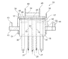
図2には、本発明に従って構成された糸スプライシング装置10が、部分断面側面図で示されており、この糸スプライシング装置10は、中央の構成部材として、空気分配体18を有しており、この空気分配体18は、圧縮空気管路26,27のための接続孔19,23と、保持兼解撚管17のための収容孔30とを備えている。空気分配体18は、これに対応する収容装置を介して作業ユニット2の作業ユニットハウジング33に結合されている。中央に配置された接続孔23とこれに所属の圧縮空気管路26とを介して、このとき必要な場合に、スプライシング空気をスプライシング角柱体34のスプライシング通路35内に吹き込むことができ、これに対して接続孔19および圧縮空気供給管路27を介して、収容孔30内に配置された保持兼解撚管17に空気が供給される。すなわち、後続のスプライシング工程においてスプライシング角柱体34のスプライシング通路35内で本来の糸とほぼ同じように糸継ぎされるべき、保持兼解撚管17内に配置された糸端部は、圧縮空気供給管路27を介して圧縮空気の吹込みによってスプライシング工程のために適正に準備、即ち解撚される。
FIG. 2 shows a
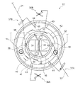
図3からも明らかに分かるように、糸スプライシング装置10の空気分配体18には、回動可能に支承された少なくとも2つの制御エレメント41,42が配置されており、これらの制御エレメント41,42はそれぞれ、個別駆動装置によって規定通りに駆動可能である。すなわち、制御エレメント41,42はそれぞれ1つの歯列を有しており、この歯列は、これに所属の個別駆動装置のモータ軸に配置されたピニオンに対応する。好ましくはステップモータとして構成された個別駆動装置は、このときそれ自体それぞれ制御ラインを介して、該当する作業ユニット2の作業ユニットコンピュータ29に接続されていて、この作業ユニットコンピュータ29によって必要に応じて制御可能である。図面から分かるように、制御エレメント41は、糸スプライシング装置10の領域に取り付けられた糸ハンドリング装置(例えば糸切断装置36A,36Bおよび糸クランプ装置37A,37B)を作動させる切換え突子43,44を有している。
As can be clearly seen from FIG. 3, the
制御エレメント42は、糸寄せ器38を備えており、この糸寄せ器38は、スプライシング工程中に保持兼解撚管17内において準備された糸端部が、糸寄せ器38のアームによって、必要に応じてスプライシング角柱体34のスプライシング通路35内だけでなく、コントロール下でスプライシング角柱体34のベース体45の糸ガイド溝46内で位置決め可能であるように、形成されかつ配置されている。
The
図3には、図2の糸スプライシング装置10が平面図で示されている。図面から分かるように、円形の外周部を有する空気分配体18には、スプライシング角柱体34が配置されており、このスプライシング角柱体34は、空気を供給可能なスプライシング通路35を有している。スプライシング角柱体34は、ベース体45に固定されているか、またはそれ自体が、環状の糸ガイド溝46を有しかつスプライシング通路35の出口側にはそれぞれ漏斗状の出口開口48を備えているベース体45の構成部材である。このとき出口開口48の領域には、保持兼解撚管17用の収容孔30がそれぞれ1つ配置されている。さらにスプライシング通路の出口領域には、それぞれ糸ガイド金属薄板49が設置されており、これらの糸ガイド金属薄板49は、吸込みノズル12またはグリッパ管25によって収容された上糸および下糸31,32の糸端部の、スプライシング角柱体34のスプライシング通路35内への挿通を著しく容易にする。
FIG. 3 is a plan view of the
図3から良好に分かるように、空気分配体18の外周部には、制限されて回動可能に制御エレメント41,42が支承されており、これらの制御エレメント41,42は、その外周部の一部にそれぞれ歯列51,52を有している。制御エレメント42の歯列52は、例えばピニオンと噛み合っており、このピニオンは、好ましくはステップモータとして形成されかつ作業ユニット2の作業ユニットコンピュータ29に接続されている所属の個別駆動装置のモータ軸に配置されている。制御エレメント42は、さらに糸寄せ器38を備えており、この糸寄せ器38は、必要な場合に、スプライシングすべき糸端部を、スプライシング角柱体34のスプライシング通路47内において適正に位置決めして、これらの糸端部を、スプライシング工程中にコントロール下でベース体45の糸ガイド溝46に拘束させる。
As can be seen from FIG. 3,
制御エレメント41は、歯列51を有しており、この歯列51は、同様に個別駆動装置のモータ軸に配置されたピニオンと対応し、個別駆動装置自体は、制御ラインを介して、作業ユニット2の作業ユニットコンピュータ29に接続されている。制御エレメント41は、さらに切換え突子43,44を備えており、これらの切換え突子43,44は、糸切断装置36を作動させるため、もしくは糸クランプ装置37を作動させるために働く。
The
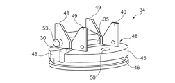
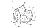
図4および5は、それぞれ斜め方向から見た側面図で、もしくは斜め方向から見た平面図で、本発明に従って構成されたスプライシング角柱体34を示している。図示された実施形態の場合、スプライシング通路35を有するスプライシング角柱体34と、糸ガイド溝46および出口開口48を備えるベース体45とは、一体的に結合されている。図面から分かるように、それぞれスプライシング角柱体34のスプライシング通路35の端部側で、1つの出口開口48が配置されていて、それぞれ保持兼解撚管17用の収容孔30を有している。さらにスプライシング通路35の出口側では、糸ガイド金属薄板49が配置されており、これらの糸ガイド金属薄板49は、上糸および下糸31,32のスプライシングすべき糸端部の、スプライシング通路35内への挿通を著しく容易にする。糸ガイド金属薄板49は、例えばねじボルト53によって、スプライシング角柱体34に取り付けられている。スプライシング角柱体34は、それ自体が、好ましくは同様にねじボルトによって空気分配体18に固定可能であって、そのために取付孔50を有している。
4 and 5 each show a
本発明による糸スプライシング装置の機能
公知のように、糸スプライシング装置は、自動綾巻きワインダ1の作業ユニット2において糸の切断によって巻取りの中断が生じると使用される。このときこのような巻取りの中断は、糸切れまたはコントロール下の糸クリアリング切断に起因するとみなしてよい。すなわち、このような自動綾巻きワインダ1の作業ユニット2において、走行する糸は巻取り作業中に連続的にそれぞれ糸クリアラによって監視され、この糸クリアラは、各々の糸不均一部を検知して、それを直ちに該当の作業ユニット2の作業ユニットコンピュータ29に通知する。作業ユニットコンピュータ29それ自体は、必要な場合に直ちに、規定通りに糸切断を開始し、この糸切断時に、走行する糸は、糸クリアラの領域に配置された公知の糸切断装置によって、上糸31と下糸32とに切り離される。次いで上糸31は、パッケージフレームに回転可能に保持されかつ制動モーメントを加えられた綾巻きパッケージ15の表面に巻き上げられ、これに対して下糸32は、通常いわゆる糸テンショナにおいて保持される。
Functions of the yarn splicing device according to the invention As is known in the art, the yarn splicing device is used in the working unit 2 of the automatic traverse winder 1 when winding is interrupted by cutting the yarn. At this time, such winding interruption may be considered to be caused by yarn breakage or yarn clearing cut under control. That is, in the working unit 2 of the automatic winding machine 1, the traveling yarn is continuously monitored by the yarn clearer during the winding operation, and the yarn clearer detects each non-uniform portion of the yarn. This is immediately notified to the
欠陥のある糸部分のクリアリング除去のため、かつ新しい糸継ぎ部の形成のために、次いで、綾巻きパッケージ15に巻き上げられた上糸31が再び受け取られる。すなわち、吸込みノズル12が上方に向かって旋回させられ、負圧を加えることが可能なその開口が、綾巻きパッケージ15の表面の領域において位置決めされ、このとき綾巻きパッケージ15は同時にゆっくりと繰出し方向に回転させられる。吸込みノズル12が上糸31の糸端部を受け取ると直ちに、吸込みノズル12の領域に配置された糸切断装置(図示せず)を用いて、欠陥のある糸部分が切り離されて廃棄される。
The
次いで、いまや欠陥のない上糸31が、吸込みノズル12によって糸スプライシング装置10の領域に搬送されて、その領域において糸ガイド金属薄板49によって案内されて、スプライシング角柱体34のスプライシング通路35内に挿通される。このとき上糸31は、さらに上側の糸クランプ装置37B内に、かつ下側の糸切断装置36Aの工具の間に挿入される。
Next, the
上糸31の受取りと同時にまたは時間的に幾分か遅れて、グリッパ管25は、コントロール下の糸切断後に通常糸テンショナにおいて固定されている下糸32の糸端部を迎えに行く。すなわち、グリッパ管25は、下糸32を糸テンショナから糸スプライシング装置10へ搬送し、その糸を糸ガイド金属薄板49によって案内させて、逆の方向からスプライシング角柱体34のスプライシング通路35に挿入する。このとき下糸32はさらに、下側の糸クランプ装置37Aおよび上側の糸切断装置36Bに挿通される。
Simultaneously with the receipt of the
上糸31および下糸32の糸端部がスプライシング角柱体34のスプライシング通路35内に挿入されると直ちに、それらの糸端部は、糸クランプ装置37A,37Bによって機械式に固定され、かつ糸切断装置36A,36Bによって適正に所定の長さで切断される。
As soon as the yarn ends of the
次いで、糸寄せ器38は、上糸31および下糸32の糸端部が、スプライシング角柱体34のスプライシング通路35の出口側に配置された保持兼解撚管17の領域へそれぞれ移動され、かつ保持兼解撚管17によって吸い込まれるように、駆動制御される。このとき保持兼解撚管17は、有利には、スプライシング角柱体34のベース体45の出口開口48の領域に配置された収容孔30内に固定されている。それから糸寄せ器38は、再び戻し旋回されて、その結果、所定の長さの糸端部が保持兼解撚管17内に吸引されて、保持兼解撚管17内で空気力によってスプライシング工程のために準備される。すなわち、上糸31および下糸32の、保持兼解撚管17内に吸い込まれた糸端部においては、十分にその糸撚りが解されかつ短繊維が除去される。
Next, the
次いで、準備された糸端部は、糸寄せ器38によって保持兼解撚管17から再び引き出され、そしてそれらの糸端部が適正な方向付けおよび規定通りの重なり部分を有するようにスプライシング角柱体34のスプライシング通路35内に位置決めされる。糸寄せ器38は、そのために回動させられて、その結果、糸寄せ器38のアームは、糸クランプ装置37Aもしくは37Bとスプライシング角柱体34のスプライシング通路35との間においてそれぞれ延びる、上糸31および下糸32の糸ストランドと交差し、このとき自由な糸端部を保持兼解撚管17から引き出す。さらに糸寄せ器38は、糸ストランドの主要部分がコントロール下でスプライシング角柱体34のベース体45の糸ガイド溝46に収容されるように働き、その結果、スプライシング工程中に、空気力によってかけられた糸撚りの一部がスプライシング通路35から出て糸ストランドの主要部分に伝達することを阻止する。
The prepared yarn ends are then withdrawn from the holding and untwisting
すなわち、適正にスプライシング角柱体34のスプライシング通路35に位置決めされかつベース体45の糸ガイド溝46にコントロール下で拘束された、上糸31および下糸32の糸端部は、圧縮空気管路26と空気分配体18の接続孔23とを介してスプライシング空気をスプライシング角柱体34のスプライシング通路35内に吹き込み、かつこのときまずスプライシング通路35内でほぼ平行に配向された、両糸端部の繊維を、相互に本来の糸とほぼ同じように糸継ぎされるように渦動させることによって、本来の糸とほぼ同じように空気力によって糸継ぎされる。
That is, the thread ends of the
糸継ぎ工程は、これによって終了し、該当する作業ユニット2は巻取り工程に進むことができる。 The yarn splicing process is thereby completed, and the corresponding work unit 2 can proceed to the winding process.
Claims (7)
圧縮空気を供給可能なスプライシング通路(35)を有する、空気分配体(18)に固定可能なスプライシング角柱体(34)と、該スプライシング角柱体(34)に対して間隔を置いて配置されていて、制限されて回動可能に支承された糸寄せ器(38)とを備える、糸スプライシング装置(10)において、
前記スプライシング角柱体(34)の領域に、上糸および下糸(31,32)の糸端部を収容する糸ガイド溝(46)が配置されていて、かつ前記スプライシング角柱体(34)の前記スプライシング通路(35)の出口側に、保持兼解撚管(17)用の収容孔(30)を有する、漏斗状に形成された出口開口(48)がそれぞれ1つ配置されていることを特徴とする、綾巻きパッケージを製造する繊維機械(1)の作業ユニット(2)用の糸スプライシング装置(10)。 A yarn splicing device (10) for a work unit (2) of a textile machine (1) for producing a traverse package,
A splicing prism (34) fixed to the air distributor (18) having a splicing passage (35) capable of supplying compressed air, and spaced from the splicing prism (34); A yarn splicing device (10) comprising a restricted and pivotally supported yarn feeder (38),
In the region of the splicing prismatic body (34), a thread guide groove (46) that accommodates the thread ends of the upper thread and the lower thread (31, 32) is disposed, and the splicing prismatic body (34) One outlet opening (48) formed in a funnel shape having an accommodation hole (30) for the holding and untwisting tube (17) is disposed on the outlet side of the splicing passage (35). A yarn splicing device (10) for a work unit (2) of a textile machine (1) for manufacturing a traverse package.
Applications Claiming Priority (2)
| Application Number | Priority Date | Filing Date | Title |
|---|---|---|---|
| DE102016119542.1 | 2016-10-13 | ||
| DE102016119542.1A DE102016119542A1 (en) | 2016-10-13 | 2016-10-13 | Thread splicing device for a workstation of a cross-wound textile machine |
Publications (1)
| Publication Number | Publication Date |
|---|---|
| JP2018062425A true JP2018062425A (en) | 2018-04-19 |
Family
ID=61764652
Family Applications (1)
| Application Number | Title | Priority Date | Filing Date |
|---|---|---|---|
| JP2017199325A Pending JP2018062425A (en) | 2016-10-13 | 2017-10-13 | A yarn splicing device for a work unit of a textile machine for manufacturing a chewy package |
Country Status (3)
| Country | Link |
|---|---|
| JP (1) | JP2018062425A (en) |
| CN (1) | CN107934682B (en) |
| DE (1) | DE102016119542A1 (en) |
Cited By (2)
| Publication number | Priority date | Publication date | Assignee | Title |
|---|---|---|---|---|
| CN115537989A (en) * | 2022-10-08 | 2022-12-30 | 安徽迪惠新材料科技有限公司 | Spinning process of antistatic and antibacterial yarn |
| JP7637483B2 (en) | 2019-08-16 | 2025-02-28 | リーター オートマティック ワインダー ゲー・エム・ベー・ハー | Splicing unit for textile machine splicers |
Families Citing this family (7)
| Publication number | Priority date | Publication date | Assignee | Title |
|---|---|---|---|---|
| DE102018102757A1 (en) * | 2018-02-07 | 2019-08-08 | Saurer Spinning Solutions Gmbh & Co. Kg | yarn splicing |
| EP3643819B1 (en) * | 2018-09-11 | 2025-03-19 | Lakshmi Machine Works Ltd. | Yarn picking arrangement for a ring spinning machine and a method thereof |
| CN110846749B (en) * | 2019-11-07 | 2022-05-13 | 义乌市明荣线业有限公司 | Wire guiding device capable of automatically adjusting yarn clamping force and twisting |
| DE102021108703A1 (en) * | 2021-04-08 | 2022-10-13 | Saurer Spinning Solutions Gmbh & Co. Kg | Thread splicing device for a work station of a textile machine producing cross-wound bobbins |
| PT4177200T (en) * | 2021-11-04 | 2026-06-15 | Saurer Intelligent Technology AG | Thread guiding element and yarn cleaner for a work station of a textile machine with a thread guiding element |
| DE102023114441A1 (en) * | 2023-06-01 | 2024-12-05 | Rieter Automatic Winder GmbH | Thread connecting device for a workstation of a textile machine producing winding packages |
| DE102023114438A1 (en) * | 2023-06-01 | 2024-12-05 | Rieter Automatic Winder GmbH | Thread connecting device for a workstation of a textile machine producing winding packages |
Family Cites Families (10)
| Publication number | Priority date | Publication date | Assignee | Title |
|---|---|---|---|---|
| DE4008640A1 (en) * | 1990-03-17 | 1991-09-19 | Stahlecker Gmbh Wilhelm | SPLITTING DEVICE FOR CONNECTING THREADS |
| JPH07133079A (en) * | 1993-11-09 | 1995-05-23 | Murata Mach Ltd | Splicer |
| DE4420979B4 (en) | 1994-06-16 | 2005-09-01 | Saurer Gmbh & Co. Kg | Fadenendevorbereitungseinrichtung for cross-wound textile machinery manufacturing |
| CH692624A5 (en) | 1998-03-19 | 2002-08-30 | Textilma Ag | Electrical rotary engine in particular for a textile machine. |
| DE19858548A1 (en) | 1998-12-18 | 2000-06-21 | Schlafhorst & Co W | Electromechanical drive for the reciprocating yarn guide for winding cross wound bobbins has a structured air gap with magnetic field lines through it acting on a coil at the yarn guide |
| DE10202781A1 (en) * | 2002-01-25 | 2003-07-31 | Schlafhorst & Co W | Device for the pneumatic connection of yarns |
| DE10224080A1 (en) | 2002-05-31 | 2003-12-11 | Schlafhorst & Co W | Textile machine has cross-wound bobbin winder with thread splicing unit having a separate drive for a predefined drive control |
| DE102004025519A1 (en) | 2004-05-25 | 2005-12-15 | Saurer Gmbh & Co. Kg | Method and device for operating a winding device of a cross-wound producing textile machine |
| CN201447265U (en) * | 2009-07-28 | 2010-05-05 | 湛江中湛纺织有限公司 | Yarn joiner |
| DE102011101629A1 (en) * | 2011-05-14 | 2012-11-15 | Oerlikon Textile Gmbh & Co. Kg | Thread splicing device for automatic cheese winder, has smoothening zone extending over length in thread longitudinal direction, where length corresponds to thread ends projecting from channel during splicing process |
-
2016
- 2016-10-13 DE DE102016119542.1A patent/DE102016119542A1/en not_active Withdrawn
-
2017
- 2017-10-10 CN CN201710933402.0A patent/CN107934682B/en active Active
- 2017-10-13 JP JP2017199325A patent/JP2018062425A/en active Pending
Cited By (2)
| Publication number | Priority date | Publication date | Assignee | Title |
|---|---|---|---|---|
| JP7637483B2 (en) | 2019-08-16 | 2025-02-28 | リーター オートマティック ワインダー ゲー・エム・ベー・ハー | Splicing unit for textile machine splicers |
| CN115537989A (en) * | 2022-10-08 | 2022-12-30 | 安徽迪惠新材料科技有限公司 | Spinning process of antistatic and antibacterial yarn |
Also Published As
| Publication number | Publication date |
|---|---|
| CN107934682B (en) | 2019-06-18 |
| DE102016119542A1 (en) | 2018-04-19 |
| CN107934682A (en) | 2018-04-20 |
Similar Documents
| Publication | Publication Date | Title |
|---|---|---|
| JP6930877B2 (en) | Thread splicing equipment for working units of textile machines that manufacture twill-wound packages | |
| JP5943700B2 (en) | Yarn splicing device for the working position of textile machine to manufacture twill winding package | |
| CN107934682B (en) | For manufacturing the yarn splicing device of the station of the weaving loom of cross winding bobbin | |
| CN101454231B (en) | Method for operating a workstation of a textile machine which produces crosswound bobbins | |
| EP2573017B1 (en) | Yarn winding unit, yarn winding apparatus and spinning machine | |
| CN1295125C (en) | Apparatus for pneumatically connecting ends of yarns | |
| JP6895774B2 (en) | Thread splicing equipment for working units of textile machines that manufacture twill-wound packages | |
| EP2441718B1 (en) | Yarn winding apparatus | |
| JP2019011544A (en) | Yarn splicing apparatus for pneumatic power type piecing of yarn end part | |
| JP6080428B2 (en) | Yarn Splicing Equipment for Textile Machine Manufacturing Twill Roll Package | |
| JPH01281261A (en) | Yarn doubling winder | |
| JP2016003089A (en) | Automatic winder and thread winding method | |
| JP7085937B2 (en) | A device that clears and removes thread defects from threads | |
| JPH026643A (en) | Fine spinning frame equipped with many fine spinning devices for producing bobbin used as twisting supply bobbin | |
| JP2016137959A (en) | Yarn winder | |
| EP1712504B1 (en) | Device and process for the handling and control of the yarn in a crosswinding head of a crosswinding machine in bobbin doffing operations | |
| EP1616829B1 (en) | Yarn guide device of revolving type automatic winder | |
| JP2004323219A (en) | Automatic winder | |
| JP7222686B2 (en) | Yarn splicing equipment for textile machinery | |
| CN111747233B (en) | Method for producing a piecing connection at a textile machine station and textile machine station | |
| JP6861502B2 (en) | A method for correcting yarn run in the working unit of a textile machine that manufactures twill-wound packages | |
| CN1847130B (en) | Device and process for handling and controlling the yarn of a crosswinding head of a crosswinding machine during the starting operations of a new lot | |
| JP2019026482A (en) | Yarn splicing device which splices yarn aerodynamically | |
| JP2024533087A (en) | Yarn splicing device for a work station of a textile machine for producing twill packages | |
| JP7060404B2 (en) | Thread splicing device for working units of automatic twill winder |