JP2018093717A - 過電圧保護装置及び方法 - Google Patents
過電圧保護装置及び方法 Download PDFInfo
- Publication number
- JP2018093717A JP2018093717A JP2017230778A JP2017230778A JP2018093717A JP 2018093717 A JP2018093717 A JP 2018093717A JP 2017230778 A JP2017230778 A JP 2017230778A JP 2017230778 A JP2017230778 A JP 2017230778A JP 2018093717 A JP2018093717 A JP 2018093717A
- Authority
- JP
- Japan
- Prior art keywords
- patient
- bias
- voltage
- resistor
- limiting device
- Prior art date
- Legal status (The legal status is an assumption and is not a legal conclusion. Google has not performed a legal analysis and makes no representation as to the accuracy of the status listed.)
- Granted
Links
Images








Classifications
-
- H—ELECTRICITY
- H02—GENERATION; CONVERSION OR DISTRIBUTION OF ELECTRIC POWER
- H02H—EMERGENCY PROTECTIVE CIRCUIT ARRANGEMENTS
- H02H9/00—Emergency protective circuit arrangements for limiting excess current or voltage without disconnection
- H02H9/04—Emergency protective circuit arrangements for limiting excess current or voltage without disconnection responsive to excess voltage
- H02H9/045—Emergency protective circuit arrangements for limiting excess current or voltage without disconnection responsive to excess voltage adapted to a particular application and not provided for elsewhere
-
- A—HUMAN NECESSITIES
- A61—MEDICAL OR VETERINARY SCIENCE; HYGIENE
- A61B—DIAGNOSIS; SURGERY; IDENTIFICATION
- A61B5/00—Measuring for diagnostic purposes; Identification of persons
- A61B5/24—Detecting, measuring or recording bioelectric or biomagnetic signals of the body or parts thereof
- A61B5/30—Input circuits therefor
- A61B5/307—Input circuits therefor specially adapted for particular uses
- A61B5/308—Input circuits therefor specially adapted for particular uses for electrocardiography [ECG]
-
- A—HUMAN NECESSITIES
- A61—MEDICAL OR VETERINARY SCIENCE; HYGIENE
- A61N—ELECTROTHERAPY; MAGNETOTHERAPY; RADIATION THERAPY; ULTRASOUND THERAPY
- A61N1/00—Electrotherapy; Circuits therefor
- A61N1/02—Details
- A61N1/08—Arrangements or circuits for monitoring, protecting, controlling or indicating
-
- A—HUMAN NECESSITIES
- A61—MEDICAL OR VETERINARY SCIENCE; HYGIENE
- A61N—ELECTROTHERAPY; MAGNETOTHERAPY; RADIATION THERAPY; ULTRASOUND THERAPY
- A61N1/00—Electrotherapy; Circuits therefor
- A61N1/18—Applying electric currents by contact electrodes
- A61N1/32—Applying electric currents by contact electrodes alternating or intermittent currents
- A61N1/36—Applying electric currents by contact electrodes alternating or intermittent currents for stimulation
- A61N1/3605—Implantable neurostimulators for stimulating central or peripheral nerve system
- A61N1/36125—Details of circuitry or electric components
-
- A—HUMAN NECESSITIES
- A61—MEDICAL OR VETERINARY SCIENCE; HYGIENE
- A61N—ELECTROTHERAPY; MAGNETOTHERAPY; RADIATION THERAPY; ULTRASOUND THERAPY
- A61N1/00—Electrotherapy; Circuits therefor
- A61N1/18—Applying electric currents by contact electrodes
- A61N1/32—Applying electric currents by contact electrodes alternating or intermittent currents
- A61N1/36—Applying electric currents by contact electrodes alternating or intermittent currents for stimulation
- A61N1/3605—Implantable neurostimulators for stimulating central or peripheral nerve system
- A61N1/36128—Control systems
- A61N1/36142—Control systems for improving safety
-
- A—HUMAN NECESSITIES
- A61—MEDICAL OR VETERINARY SCIENCE; HYGIENE
- A61N—ELECTROTHERAPY; MAGNETOTHERAPY; RADIATION THERAPY; ULTRASOUND THERAPY
- A61N1/00—Electrotherapy; Circuits therefor
- A61N1/18—Applying electric currents by contact electrodes
- A61N1/32—Applying electric currents by contact electrodes alternating or intermittent currents
- A61N1/36—Applying electric currents by contact electrodes alternating or intermittent currents for stimulation
- A61N1/362—Heart stimulators
- A61N1/37—Monitoring; Protecting
-
- A—HUMAN NECESSITIES
- A61—MEDICAL OR VETERINARY SCIENCE; HYGIENE
- A61N—ELECTROTHERAPY; MAGNETOTHERAPY; RADIATION THERAPY; ULTRASOUND THERAPY
- A61N1/00—Electrotherapy; Circuits therefor
- A61N1/18—Applying electric currents by contact electrodes
- A61N1/32—Applying electric currents by contact electrodes alternating or intermittent currents
- A61N1/36—Applying electric currents by contact electrodes alternating or intermittent currents for stimulation
- A61N1/362—Heart stimulators
- A61N1/37—Monitoring; Protecting
- A61N1/3718—Monitoring of or protection against external electromagnetic fields or currents
-
- A—HUMAN NECESSITIES
- A61—MEDICAL OR VETERINARY SCIENCE; HYGIENE
- A61N—ELECTROTHERAPY; MAGNETOTHERAPY; RADIATION THERAPY; ULTRASOUND THERAPY
- A61N1/00—Electrotherapy; Circuits therefor
- A61N1/18—Applying electric currents by contact electrodes
- A61N1/32—Applying electric currents by contact electrodes alternating or intermittent currents
- A61N1/38—Applying electric currents by contact electrodes alternating or intermittent currents for producing shock effects
- A61N1/39—Heart defibrillators
- A61N1/3925—Monitoring; Protecting
-
- H—ELECTRICITY
- H02—GENERATION; CONVERSION OR DISTRIBUTION OF ELECTRIC POWER
- H02H—EMERGENCY PROTECTIVE CIRCUIT ARRANGEMENTS
- H02H9/00—Emergency protective circuit arrangements for limiting excess current or voltage without disconnection
- H02H9/005—Emergency protective circuit arrangements for limiting excess current or voltage without disconnection avoiding undesired transient conditions
-
- H—ELECTRICITY
- H03—ELECTRONIC CIRCUITRY
- H03K—PULSE TECHNIQUE
- H03K17/00—Electronic switching or gating, i.e. not by contact-making and –breaking
- H03K17/08—Modifications for protecting switching circuit against overcurrent or overvoltage
- H03K17/081—Modifications for protecting switching circuit against overcurrent or overvoltage without feedback from the output circuit to the control circuit
- H03K17/08104—Modifications for protecting switching circuit against overcurrent or overvoltage without feedback from the output circuit to the control circuit in field-effect transistor switches
-
- A—HUMAN NECESSITIES
- A61—MEDICAL OR VETERINARY SCIENCE; HYGIENE
- A61B—DIAGNOSIS; SURGERY; IDENTIFICATION
- A61B2562/00—Details of sensors; Constructional details of sensor housings or probes; Accessories for sensors
- A61B2562/18—Shielding or protection of sensors from environmental influences, e.g. protection from mechanical damage
Landscapes
- Health & Medical Sciences (AREA)
- Life Sciences & Earth Sciences (AREA)
- Animal Behavior & Ethology (AREA)
- Veterinary Medicine (AREA)
- Public Health (AREA)
- Engineering & Computer Science (AREA)
- Biomedical Technology (AREA)
- General Health & Medical Sciences (AREA)
- Nuclear Medicine, Radiotherapy & Molecular Imaging (AREA)
- Radiology & Medical Imaging (AREA)
- Heart & Thoracic Surgery (AREA)
- Cardiology (AREA)
- Neurology (AREA)
- Neurosurgery (AREA)
- Physics & Mathematics (AREA)
- Electromagnetism (AREA)
- Biophysics (AREA)
- Pathology (AREA)
- Medical Informatics (AREA)
- Molecular Biology (AREA)
- Surgery (AREA)
- Electrotherapy Devices (AREA)
- Emergency Protection Circuit Devices (AREA)
Abstract
Description
Claims (15)
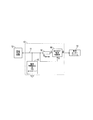
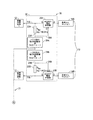
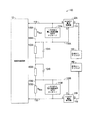
- 第1の端部と第2の端部とを接続する第1の配線と、
前記第1の端部と前記第2の端部との間の前記第1の配線に接続された電流制限装置であって、前記電流制限装置はオン状態とオフ状態とを有し、前記オフ状態のときに通過する電流を前記第1の端部と前記第2の端部との間に制限し、所定のバイアス電圧に応答して前記オン状態から前記オフ状態に切り替わるように構成された前記電流制限装置と、
前記第1の配線から延在する第2の配線と、
前記第2の配線に接続され、少なくとも1つのバイアス素子と、少なくとも1つのバイアス電圧生成装置と直列に接続された追加の回路素子とを有するバイアス電圧生成回路と、
前記第1の配線の過渡過電圧に応答して前記電流制限装置に前記所定のバイアス電圧を印加するように構成された前記バイアス素子と前記追加の回路素子と、
を有し、
前記電流制限装置は、スイッチオフされ、前記第1の配線を流れる電流を制限する、過電圧保護装置。 - 前記第1の配線は医療機器の第1の患者側配線であり、前記第1の端部は前記医療機器の内部回路と通信し、前記第2の端部は患者インターフェースを有する、請求項1に記載の過電圧保護装置。
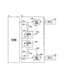
- それぞれのバイアス抵抗は、50オームから1キロオームの範囲の抵抗を有し、
及び/又は、
前記追加の回路素子は、第1のバイアス抵抗と第2のバイアス抵抗との間に接続された少なくとも1つの電圧制限装置を有し、
及び/又は、
前記電流制限装置は、第1のデプリーション型金属酸化物半導体電界効果トランジスタ(MOSFET)と第2のデプリーション型金属酸化物半導体電界効果トランジスタ(MOSFET)とを有する、請求項2に記載の過電圧保護装置。 - 少なくとも1つの前記電圧制限装置は、過渡電圧抑制器(TVS)を有し、
及び/又は、
前記電圧制限装置は、前記第1のバイアス抵抗の前記第2の端部に接続された第1の一方向性のTVSと、前記第1の一方向性のTVSと前記第2のバイアス抵抗の前記第2の端部との間に接続された第2の一方向性のTVSと、を有する、請求項3に記載の過電圧保護装置。 - それぞれのMOSFETは、
第2の端子に接続されるドレイン端子と、
前記医療機器の前記内部回路に接続されるソース端子と、
ゲート端子と、
を有し、
前記第1のバイアス抵抗は、第1のMOSFETの前記ゲート端子に接続され、
前記第2のバイアス抵抗は、第2のMOSFETの前記ゲート端子に接続される、請求項3又は請求項4に記載の過電圧保護装置。 - 少なくとも1つの前記追加の回路素子は、
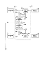
第1のバイアス抵抗と直列に接続されて第1の分圧器を形成する第1の抵抗と、
第2のバイアス抵抗と直列に接続されて第2の分圧器を形成する第2の抵抗と、
第1の電流制限装置に接続された前記第1のバイアス抵抗と前記第1の抵抗との間の第1の接続部と、
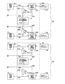
第2の電流制限装置に接続された前記第2のバイアス抵抗と前記第2の抵抗との間の第2の接続部と、を有する、請求項2乃至請求項5のいずれか1項に記載の過電圧保護装置。 - 前記第1の患者側配線と第2の患者側配線と、反対側にある前記第1の端部と前記第2の端部と、を有する第2の患者チャネルと、
前記医療機器の前記内部回路と通信するそれぞれの前記第1の端部と、
それぞれ第1の患者インターフェースと第2の患者インターフェースと、前記第2の患者チャネルの前記第1の患者側配線と前記第2の患者側配線とにそれぞれ第1の電流制限装置と第2の電流制限装置とを有する前記第2の端部と、
前記第2の患者チャネルの前記第1の患者側配線と前記第2の患者側配線との間に延在する前記第2の配線に接続された第1のバイアス電圧生成回路と同一であり、前記第2の患者チャネルのそれぞれ前記第1の患者側配線又は前記第2の患者側配線に過渡電圧パルスが発生した場合に、前記第2の患者チャネルの少なくともそれぞれ前記第1の電流制限装置又は前記第2の電流制限装置をオフにするバイアス電圧を生成するように構成される第2のバイアス電圧生成回路と、をさらに有し、
及び/又は、
前記第1の患者チャネルと前記第2の患者チャネルとの前記バイアス電圧生成回路の第1のバイアス素子と第2のバイアス素子とはバイアス抵抗を有し、
前記追加の回路素子は前記バイアス抵抗の間に接続された少なくとも1つの電圧制限装置を有する、請求項2乃至請求項6のいずれか1項に記載の過電圧保護装置。 - 少なくとも1つの前記追加の回路素子は、それぞれの患者チャネルの前記バイアス抵抗の間に接続された第1の一方向性の電圧制限装置と第2の一方向性の電圧制限装置とを有し、
接続配線は、前記第1の患者チャネルの前記第1の一方向性の電圧制限装置と前記第2の一方向性の電圧制限装置との間の第1の位置で接続された前記第1の端部と、前記第2の患者チャネルの前記第1の一方向性の電圧制限装置と前記第2の一方向性の電圧制限装置との間の第2の位置で接続された前記第2の端部と、を有し、
及び/又は、
それぞれの前記患者チャネルの前記追加の回路素子は、それぞれの前記患者チャネルの前記バイアス抵抗の間に接続された第1の双方向性の電圧制限装置を有し、それぞれの前記患者チャネルの第1の接続部と第2の接続部とは、第1のバイアス抵抗と双方向性の電圧制限装置との間と、第2のバイアス抵抗と双方向性の電圧制限装置との間とにそれぞれ配置され、
第1の電流経路は、前記第1の患者チャネルの前記第1の接続部と前記第2の患者チャネルの前記第2の接続部との間に延在し、第2の双方向性の電圧制限装置が前記第1の電流経路に配置され、
第2の電流経路は、前記第1の患者チャネルの前記第1の接続部と前記第2の患者チャネルの前記第1の接続部との間に延在し、第3の双方向性の電圧制限装置が前記第2の電流経路に配置され、
第3の電流経路は、前記第1の患者チャネルの前記第2の接続部と前記第2の患者チャネルの前記第1の接続部との間に延在し、第4の双方向性の電圧制限装置が前記第3の電流経路に配置され、
第4の電流経路は、前記第1の患者チャネルの前記第2の接続部と前記第2の患者チャネルの前記第2の接続部との間に延在し、第5の双方向性の電圧制限装置が前記第4の電流経路に配置される、請求項7に記載の過電圧保護装置。 - 前記第1の患者側配線と前記第2の患者側配線と、反対側にある前記第1の端部と前記第2の端部と、を有する第3の患者チャネルと、
前記医療機器の前記内部回路と通信するそれぞれの前記第1の端部と、
それぞれ前記第1の患者インターフェースと前記第2の患者インターフェースと、前記第3の患者チャネルの前記第1の患者側配線と前記第2の患者側配線とにそれぞれ前記第1の電流制限装置と前記第2の電流制限装置とを有する前記第2の端部と、
前記第2の患者チャネルの前記第1のバイアス電圧生成回路と前記第2のバイアス電圧生成回路と同一であり、前記第3の患者チャネルのそれぞれ前記第1の患者側配線又は前記第2の患者側配線に過渡電圧パルスが発生した場合に、前記第3の患者チャネルの少なくともそれぞれ前記第1の電流制限装置又は前記第2の電流制限装置をオフにするバイアス電圧を生成するように構成される第3のバイアス電圧生成回路と、をさらに有する、請求項7又は請求項8に記載の過電圧保護装置。 - 前記第1の患者チャネルと前記第2の患者チャネルとの前記バイアス電圧生成回路の前記第1のバイアス素子と前記第2のバイアス素子とは、第1のバイアス抵抗と第2のバイアス抵抗とを有し、
少なくとも1つの前記追加の回路素子は、前記第1のバイアス抵抗と直列に接続された第1の抵抗と、前記第2のバイアス抵抗並びに第1の分圧器と第2の分圧器とを形成する前記第1の抵抗と直列に接続される第2の抵抗と、前記第1の電流制限装置に接続された前記第1の分圧器の抵抗の間の接続部と、前記第2の電流制限装置に接続された前記第2の分圧器の抵抗との間の接続部と、を有し、
少なくとも1つの接続配線は、前記第1の患者チャネルの前記第1の抵抗と前記第2の抵抗との間に接続された前記第1の端部と、前記第2の患者チャネルの前記第1の抵抗と前記第2の抵抗との間に接続された前記第2の端部とを有する、請求項7乃至請求項9のいずれか1項に記載の過電圧保護装置。 - 1つ以上の電子部品と、
医療機器の電子部品の間で電気信号を伝える第1の患者側配線と第2の患者側配線とを有し、前記第1の患者側配線と前記第2の患者側配線とにそれぞれ接続される第1の患者インターフェースと第2の患者インターフェースとを有する少なくとも1つの患者チャネルと、
を有し、
前記患者チャネルに関連付けられ、前記第1の患者側配線に配置された第1の電流制限装置と、前記第2の患者側配線に配置された第2の電流制限装置と、前記第1の患者側配線と前記第2の患者側配線との外側にそれぞれ配置された第1のバイアス電圧生成装置と第2のバイアス電圧生成装置とを有し、第1の配線と第2の配線との過渡電圧に応答して、前記第1の配線又は前記第2の配線を流れる電流を制限するために、それぞれ前記第1の電流制限装置又は前記第2の電流制限装置をオフにし、所定のバイアス電圧を生成するように構成される過電圧保護回路と、を有する医療機器。 - 第1の電圧生成装置と第2の電圧生成装置とは、それぞれ前記第1の患者側配線と前記第2の患者側配線とに接続された第1の端部をそれぞれ有する各々の第1のバイアス抵抗と第2のバイアス抵抗と、バイアス電圧を制御するために、それぞれ前記第1のバイアス抵抗と前記第2のバイアス抵抗との間に接続された少なくとも1つの電圧制限装置と、を有し、
及び/又は、
少なくとも1つの前記電圧制限装置は、前記第1のバイアス抵抗と前記第2のバイアス抵抗との間に直列に接続された第1の一方向性の電圧制限装置と第2の一方向性の電圧制限装置とを有し、
及び/又は、
少なくとも1つの前記電圧制限装置は、前記第1のバイアス抵抗と前記第2のバイアス抵抗との間に接続された1つの双方向性の電圧制限装置を有し、
及び/又は、
少なくとも1つの前記電圧制限装置は、第1の分圧器を形成するために前記第2のバイアス抵抗に接続された第1の抵抗と、前記第1の分圧器と直列に接続された前記第2のバイアス抵抗に接続され、第2の分圧器を形成する第2の抵抗と、を有する、請求項11に記載の医療機器。 - 前記第1のバイアス抵抗と前記第2のバイアス抵抗とは、それぞれ10キロオームから1メガオームの範囲の抵抗を有し、前記第1の抵抗と前記第2の抵抗とはそれぞれ22キロオームから3.3メガオームの抵抗を有し、
及び/又は、
前記第1の抵抗と並列に接続された第1のコンデンサと、前記第2の抵抗と並列に接続された第2のコンデンサと、をさらに有する、請求項12に記載の医療機器。 - 前記第1の電流制限装置と前記第2の電流制限装置とは、それぞれ患者インターフェースに接続されたドレイン、前記電子部品に接続されたソース、及びゲートを有する金属酸化物半導体電界効果トランジスタ(MOSFET)を有し、それぞれのバイアス抵抗は、それぞれのMOSFETのゲートに接続される、請求項12又は請求項13に記載の医療機器。
- 体内又体表で使用され、少なくとも1つの患者インターフェースを有する電子医療機器の過電圧保護方法であって、
前記患者インターフェースと医療機器の電子部品との間の電流経路に直列に電流制限装置を接続し、
前記電流経路に接続された第1の端部を含むバイアス素子を有する前記電流経路から延在する配線のバイアス電圧生成回路と、前記バイアス素子と直列に接続された追加のバイアス電圧制限素子と、を接続し、
前記電流経路の過渡電圧に応じて、前記バイアス電圧生成回路に所定のバイアス電圧を発生させ、前記電流制限装置に前記所定のバイアス電圧を印加して前記電流制限装置をスイッチオフし、前記電子部品への前記電流経路又は前記電子部品からの前記電流経路における電流を制限する、過電圧保護方法。
Applications Claiming Priority (2)
| Application Number | Priority Date | Filing Date | Title |
|---|---|---|---|
| US15/366,914 | 2016-12-01 | ||
| US15/366,914 US10516262B2 (en) | 2016-12-01 | 2016-12-01 | Overvoltage protection device and method |
Publications (2)
| Publication Number | Publication Date |
|---|---|
| JP2018093717A true JP2018093717A (ja) | 2018-06-14 |
| JP6804429B2 JP6804429B2 (ja) | 2020-12-23 |
Family
ID=60269714
Family Applications (1)
| Application Number | Title | Priority Date | Filing Date |
|---|---|---|---|
| JP2017230778A Active JP6804429B2 (ja) | 2016-12-01 | 2017-11-30 | 過電圧保護装置及び方法 |
Country Status (3)
| Country | Link |
|---|---|
| US (1) | US10516262B2 (ja) |
| EP (1) | EP3345650B1 (ja) |
| JP (1) | JP6804429B2 (ja) |
Cited By (1)
| Publication number | Priority date | Publication date | Assignee | Title |
|---|---|---|---|---|
| JP2022167806A (ja) * | 2021-04-22 | 2022-11-04 | リテルフューズ、インコーポレイテッド | ミニ回路遮断器内のデプレッションモードmosfet又はjfet及びバイメタル温度感知スイッチによる過電流保護 |
Families Citing this family (7)
| Publication number | Priority date | Publication date | Assignee | Title |
|---|---|---|---|---|
| CN108242802A (zh) * | 2016-12-23 | 2018-07-03 | 华为技术有限公司 | 接口防护电路及设备接口 |
| CN106786459B (zh) * | 2016-12-28 | 2020-02-04 | 深圳市槟城电子有限公司 | 浪涌保护电路以及使用该电路的电子装置 |
| CN112867535B (zh) * | 2019-06-28 | 2024-04-02 | 深圳迈瑞生物医疗电子股份有限公司 | 除颤仪 |
| US11362650B2 (en) * | 2020-09-11 | 2022-06-14 | Littelfuse, Inc. | Overcurrent protection by depletion mode MOSFET and bi-metallic temperature sensing switch |
| US11637423B2 (en) | 2020-09-11 | 2023-04-25 | Littelfuse, Inc. | Overcurrent protection by depletion mode MOSFET or JFET and bi-metallic temperature sensing switch in mini circuit breaker |
| ES3056554T3 (en) * | 2022-02-04 | 2026-02-23 | Hoffmann La Roche | Electronic circuit and analyte sensor system such as a glucose sensor system and method of operating an analyte sensor and system |
| US20230344219A1 (en) * | 2022-04-26 | 2023-10-26 | G & W Electric Company | Current sensor powered fault current limiter |
Citations (5)
| Publication number | Priority date | Publication date | Assignee | Title |
|---|---|---|---|---|
| JPH11164467A (ja) * | 1997-11-28 | 1999-06-18 | Nec Corp | 過電流保護回路 |
| JP2003303890A (ja) * | 2002-04-09 | 2003-10-24 | Fuji Electric Co Ltd | 過電圧保護回路 |
| JP2005102415A (ja) * | 2003-09-25 | 2005-04-14 | Nippon Kouatsu Electric Co | 雷防護装置 |
| JP2006067187A (ja) * | 2004-08-26 | 2006-03-09 | Matsushita Electric Ind Co Ltd | 過電圧過電流保護回路 |
| JP2012213250A (ja) * | 2011-03-30 | 2012-11-01 | Semiconductor Components Industries Llc | 保護回路および入出力回路 |
Family Cites Families (22)
| Publication number | Priority date | Publication date | Assignee | Title |
|---|---|---|---|---|
| US4320763A (en) | 1979-10-10 | 1982-03-23 | Telectronics Pty. Limited | Protection device for pacemaker implantees |
| US4533970A (en) | 1983-06-27 | 1985-08-06 | Motorola, Inc. | Series current limiter |
| US4513341A (en) * | 1983-07-25 | 1985-04-23 | Gte Lenkurt Incorporated | Overvoltage protection circuit for power supply |
| US4595009A (en) | 1984-02-06 | 1986-06-17 | Medtronic, Inc. | Protection circuit for implantable cardioverter |
| US4661979A (en) | 1985-09-24 | 1987-04-28 | Northern Telecom Limited | Fault protection for integrated subscriber line interface circuits |
| US4745923A (en) | 1985-11-20 | 1988-05-24 | Intermedics, Inc. | Protection apparatus for patient-implantable device |
| US4744369A (en) | 1986-10-06 | 1988-05-17 | Cherne Medical, Inc. | Medical current limiting circuit |
| US4796630A (en) | 1987-03-23 | 1989-01-10 | Telectronics N.V. | Cardiac pacemaker with combined defibrillation and electrosurgery protection |
| US5517379A (en) * | 1993-05-26 | 1996-05-14 | Siliconix Incorporated | Reverse battery protection device containing power MOSFET |
| FR2708156B1 (fr) | 1993-07-19 | 1995-10-06 | Sgs Thomson Microelectronics | Circuit de protection contre des surtensions à forte énergie à tension d'écretage contrôlée. |
| FR2708860B1 (fr) * | 1993-08-11 | 1995-10-13 | Ela Medical Sa | Circuit de protection pour dispositif électronique implantable. |
| US5585991A (en) * | 1994-10-19 | 1996-12-17 | Siliconix Incorporated | Protective circuit for protecting load against excessive input voltage |
| US6161040A (en) * | 1999-02-16 | 2000-12-12 | Pacesetter, Inc. | Current limiter for an implantable cardiac device |
| US20060238936A1 (en) * | 2005-04-25 | 2006-10-26 | Blanchard Richard A | Apparatus and method for transient blocking employing relays |
| FR2911736B1 (fr) * | 2007-01-23 | 2009-03-20 | Schneider Toshiba Inverter | Dispositif de commande d'un interrupteur de puissance et variateur comprenant un tel dipositif. |
| DE102008002330A1 (de) | 2008-06-10 | 2009-12-17 | Biotronik Crm Patent Ag | Überspannungsschutzelement |
| US8099173B2 (en) * | 2009-02-26 | 2012-01-17 | Pacesetter, Inc. | Implantable medical lead circuitry and methods for reducing heating and/or induced current |
| US8155740B2 (en) | 2009-06-23 | 2012-04-10 | Medtronic, Inc. | Constant current pacing apparatus and pacing method |
| US8914109B2 (en) * | 2009-07-07 | 2014-12-16 | Pacesetter, Inc. | Method and system for identifying a potential lead failure in an implantable medical device |
| US8861164B2 (en) * | 2011-02-04 | 2014-10-14 | Fairchild Semiconductor Corporation | Integrated overdrive and overvoltage protection device |
| US8929041B2 (en) * | 2012-02-10 | 2015-01-06 | Cardiac Pacemakers, Inc. | Electrostatic discharge protection circuit |
| US10181719B2 (en) * | 2015-03-16 | 2019-01-15 | Analog Devices Global | Overvoltage blocking protection device |
-
2016
- 2016-12-01 US US15/366,914 patent/US10516262B2/en active Active
-
2017
- 2017-11-07 EP EP17200397.2A patent/EP3345650B1/en active Active
- 2017-11-30 JP JP2017230778A patent/JP6804429B2/ja active Active
Patent Citations (5)
| Publication number | Priority date | Publication date | Assignee | Title |
|---|---|---|---|---|
| JPH11164467A (ja) * | 1997-11-28 | 1999-06-18 | Nec Corp | 過電流保護回路 |
| JP2003303890A (ja) * | 2002-04-09 | 2003-10-24 | Fuji Electric Co Ltd | 過電圧保護回路 |
| JP2005102415A (ja) * | 2003-09-25 | 2005-04-14 | Nippon Kouatsu Electric Co | 雷防護装置 |
| JP2006067187A (ja) * | 2004-08-26 | 2006-03-09 | Matsushita Electric Ind Co Ltd | 過電圧過電流保護回路 |
| JP2012213250A (ja) * | 2011-03-30 | 2012-11-01 | Semiconductor Components Industries Llc | 保護回路および入出力回路 |
Cited By (2)
| Publication number | Priority date | Publication date | Assignee | Title |
|---|---|---|---|---|
| JP2022167806A (ja) * | 2021-04-22 | 2022-11-04 | リテルフューズ、インコーポレイテッド | ミニ回路遮断器内のデプレッションモードmosfet又はjfet及びバイメタル温度感知スイッチによる過電流保護 |
| JP7757583B2 (ja) | 2021-04-22 | 2025-10-22 | リテルフューズ、インコーポレイテッド | ミニ回路遮断器内のデプレッションモードmosfet又はjfet及びバイメタル温度感知スイッチによる過電流保護 |
Also Published As
| Publication number | Publication date |
|---|---|
| JP6804429B2 (ja) | 2020-12-23 |
| US10516262B2 (en) | 2019-12-24 |
| EP3345650B1 (en) | 2019-10-23 |
| EP3345650A1 (en) | 2018-07-11 |
| US20180159322A1 (en) | 2018-06-07 |
Similar Documents
| Publication | Publication Date | Title |
|---|---|---|
| JP6804429B2 (ja) | 過電圧保護装置及び方法 | |
| US8600519B2 (en) | Transient voltage/current protection system for electronic circuits associated with implanted leads | |
| EP0228539B1 (en) | Protection apparatus for patient-implantable device | |
| US5325870A (en) | Multiplexed defibrillation electrode apparatus | |
| US6597950B2 (en) | Cardiac rhythm management system with painless defibrillation lead impedance measurement | |
| JP5819957B2 (ja) | 植込型医療デバイスにおける治療回路保護 | |
| US5591218A (en) | Current limiter for implantable electronic device lead | |
| US8099173B2 (en) | Implantable medical lead circuitry and methods for reducing heating and/or induced current | |
| WO2012078228A1 (en) | Implantable lead including a spark gap to reduce heating in mri environments | |
| EP1259290B1 (en) | Defibrillator with a solid-state multiphasic circuit | |
| JP2012500050A (ja) | 外部高エネルギー電気ショック後の増加ペーシング出力のためのシステムおよび方法 | |
| Slater et al. | neuroBi: a highly configurable neurostimulator for a retinal prosthesis and other applications | |
| US20210058047A1 (en) | Isolation amplification circuit with improved common mode rejection | |
| US9026225B2 (en) | Overvoltage protection element | |
| US11389653B2 (en) | Electrical stimulation devices and systems for safely operating such devices | |
| US8494646B2 (en) | Implantable device | |
| EP0145419A2 (en) | Direct current blocking circuit and implantable device using same | |
| DE69424101T2 (de) | Schutzschaltkreis für ein einpflanzbares elektronisches Gerät | |
| CN106877302B (zh) | 用于测量放大器的主动式保护电路 | |
| DE4002187C2 (de) | Schutzschaltung |
Legal Events
| Date | Code | Title | Description |
|---|---|---|---|
| A621 | Written request for application examination |
Free format text: JAPANESE INTERMEDIATE CODE: A621 Effective date: 20171130 |
|
| RD03 | Notification of appointment of power of attorney |
Free format text: JAPANESE INTERMEDIATE CODE: A7423 Effective date: 20180328 |
|
| A521 | Request for written amendment filed |
Free format text: JAPANESE INTERMEDIATE CODE: A821 Effective date: 20180328 |
|
| A131 | Notification of reasons for refusal |
Free format text: JAPANESE INTERMEDIATE CODE: A131 Effective date: 20190205 |
|
| A601 | Written request for extension of time |
Free format text: JAPANESE INTERMEDIATE CODE: A601 Effective date: 20190419 |
|
| A601 | Written request for extension of time |
Free format text: JAPANESE INTERMEDIATE CODE: A601 Effective date: 20190705 |
|
| A521 | Request for written amendment filed |
Free format text: JAPANESE INTERMEDIATE CODE: A523 Effective date: 20190711 |
|
| A131 | Notification of reasons for refusal |
Free format text: JAPANESE INTERMEDIATE CODE: A131 Effective date: 20200107 |
|
| A521 | Request for written amendment filed |
Free format text: JAPANESE INTERMEDIATE CODE: A523 Effective date: 20200401 |
|
| A02 | Decision of refusal |
Free format text: JAPANESE INTERMEDIATE CODE: A02 Effective date: 20200526 |
|
| A521 | Request for written amendment filed |
Free format text: JAPANESE INTERMEDIATE CODE: A523 Effective date: 20200917 |
|
| C60 | Trial request (containing other claim documents, opposition documents) |
Free format text: JAPANESE INTERMEDIATE CODE: C60 Effective date: 20200917 |
|
| A911 | Transfer to examiner for re-examination before appeal (zenchi) |
Free format text: JAPANESE INTERMEDIATE CODE: A911 Effective date: 20200923 |
|
| C21 | Notice of transfer of a case for reconsideration by examiners before appeal proceedings |
Free format text: JAPANESE INTERMEDIATE CODE: C21 Effective date: 20200929 |
|
| C272 | Notice of ex officio correction |
Free format text: JAPANESE INTERMEDIATE CODE: C272 Effective date: 20200929 |
|
| TRDD | Decision of grant or rejection written | ||
| A01 | Written decision to grant a patent or to grant a registration (utility model) |
Free format text: JAPANESE INTERMEDIATE CODE: A01 Effective date: 20201110 |
|
| A61 | First payment of annual fees (during grant procedure) |
Free format text: JAPANESE INTERMEDIATE CODE: A61 Effective date: 20201202 |
|
| R150 | Certificate of patent or registration of utility model |
Ref document number: 6804429 Country of ref document: JP Free format text: JAPANESE INTERMEDIATE CODE: R150 |
|
| R250 | Receipt of annual fees |
Free format text: JAPANESE INTERMEDIATE CODE: R250 |
|
| R250 | Receipt of annual fees |
Free format text: JAPANESE INTERMEDIATE CODE: R250 |
|
| R250 | Receipt of annual fees |
Free format text: JAPANESE INTERMEDIATE CODE: R250 |