JP2018093902A - Around Case - Google Patents
Around Case Download PDFInfo
- Publication number
- JP2018093902A JP2018093902A JP2016238142A JP2016238142A JP2018093902A JP 2018093902 A JP2018093902 A JP 2018093902A JP 2016238142 A JP2016238142 A JP 2016238142A JP 2016238142 A JP2016238142 A JP 2016238142A JP 2018093902 A JP2018093902 A JP 2018093902A
- Authority
- JP
- Japan
- Prior art keywords
- shelf
- product display
- bracket
- display shelf
- pair
- Prior art date
- Legal status (The legal status is an assumption and is not a legal conclusion. Google has not performed a legal analysis and makes no representation as to the accuracy of the status listed.)
- Pending
Links
Images




Landscapes
- Freezers Or Refrigerated Showcases (AREA)
Abstract
【課題】商品陳列棚を支持する一対のブラケットがハの字形に拡開する向きに延出して設けられているアラウンドケースであって、そのブラケットにより支持される商品陳列棚を前後方向にスライド可能とすることができるアラウンドケースを提供する。【解決手段】アラウンドケース3は、上下方向に延出する棚支柱7aに一端が取付けられ、他端が棚支柱7aから離れるにつれてハの字形に拡開する一対のブラケット14と、ブラケット14の上部に固定された固定板16と、固定板16に取付けられ、棚支柱7aから離れる方向に延出して平行に対向する一対のスライドレール17と、スライドレール17を介して棚支柱7aに対して接離する方向にスライド可能にブラケット14に支持された商品陳列棚8aと、を有する。【選択図】図3PROBLEM TO BE SOLVED: To provide an around case in which a pair of brackets supporting a product display shelf extend in a direction of expanding in a C shape, and the product display shelf supported by the bracket can be slid in the front-rear direction. Provide an around case that can be. SOLUTION: Around case 3 has a pair of brackets 14 having one end attached to a shelf support 7a extending in the vertical direction and expanding in a V shape as the other end moves away from the shelf support 7a, and an upper part of the bracket 14. A pair of slide rails 17 that are attached to the fixing plate 16 and extend in a direction away from the shelf support 7a and face each other in parallel, and are in contact with the shelf support 7a via the slide rail 17. It has a product display shelf 8a supported by a bracket 14 so as to be slidable in a direction of separation. [Selection diagram] Fig. 3
Description
本発明は、周囲の三方向に商品陳列棚が設けられ、例えば、直ケースの端部に連結して使用されるアラウンドケースに関する。 The present invention relates to an around case that is provided with merchandise display shelves in three surrounding directions and is used by being connected to an end of a straight case, for example.
従来、スーパーマーケットやコンビニエンスストア等の店舗では各種のショーケースが使用されており、例えば、下記特許文献1に記載されているように、背中合わせに配置された一対の直ケースとアラウンドケースとを組み合わせた構造のショーケースが使用されている。なお、直ケースには、ケースの長手方向に沿った位置に商品陳列棚が設けられ、アラウンドケースには、周囲の三方向に商品陳列棚が設けられている。
Conventionally, various showcases are used in stores such as supermarkets and convenience stores. For example, as described in
このようなショーケースにおいては、商品陳列棚を前後方向(手前側位置と奥側位置)にスライド可能としたものが知られている。そして、商品陳列棚上に商品を陳列する場合に、商品陳列棚を手前側位置にスライドさせてその商品陳列棚を作業者の手元近くに位置させることにより、商品陳列作業の効率化を図ることができる。 In such a showcase, a product display shelf that is slidable in the front-rear direction (front side position and back side position) is known. And when displaying products on the product display shelf, the product display shelf is slid to the front side position so that the product display shelf is positioned close to the operator's hand, thereby improving the efficiency of the product display work. Can do.
商品陳列棚を前後方向にスライドさせる構造としては、例えば、下記特許文献2に記載されたものが知られている。下記特許文献2に記載されたショーケースでは、前後方向に延出して平行に対向する一対のブラケットをショーケースの左右両側に設け、これらのブラケットに平行に対向する一対のスライドレールを取付け、これらのスライドレールを介して商品陳列棚をブラケットにスライド可能に支持している。
As a structure for sliding a merchandise display shelf in the front-rear direction, for example, a structure described in
ここで、直ケースの商品陳列棚やアラウンドケースの背中合わせに位置する商品陳列棚(第1、第2の商品陳列棚)においては、それらの商品陳列棚を支持するブラケットが平行に対向して設けられている。このため、そのブラケットにスライドレールを取付けることにより、スライドレールは平行に対向することになり、商品陳列棚をスライド可能に支持することが容易にできる。 Here, in the product display shelves (first and second product display shelves) positioned back to back of the direct case product display shelves and the around case, the brackets that support the product display shelves are provided in parallel and facing each other. It has been. For this reason, by attaching a slide rail to the bracket, the slide rails face each other in parallel, and the product display shelf can be easily slidably supported.
しかしながら、アラウンドケースにおける背中合わせに位置する一対の商品陳列棚(第1、第2商品陳列棚)の間に位置する商品陳列棚(第3の商品陳列棚)は、その第3商品陳列棚の先端側コーナー部が商品の重みで垂れ下がりを生じないようにするため、その第3商品陳列棚を支持する一対のブラケットは、先端側に向かうにつれてハの字形に拡開する形状とされている。したがって、これらのブラケットにスライドレールを取付けても、取付けられた一対のスライドレールは平行にならず、アラウンドケースにおける第3の商品陳列棚を前後方向にスライド可能に支持することはできなかった。 However, the product display shelf (third product display shelf) positioned between the pair of product display shelves (first and second product display shelves) positioned back to back in the around case is the tip of the third product display shelf. In order not to cause the side corner portion to hang down due to the weight of the product, the pair of brackets that support the third product display shelf have a shape that expands in a square shape toward the tip side. Therefore, even if the slide rails are attached to these brackets, the attached pair of slide rails are not parallel, and the third commodity display shelf in the around case cannot be slidably supported in the front-rear direction.
本発明は、このような課題を解決するためになされたものであり、その目的は、商品陳列棚を支持する一対のブラケットがハの字形に拡開する向きに延出して設けられているアラウンドケースであって、そのブラケットにより支持される商品陳列棚を前後方向にスライド可能に支持することができるアラウンドケースを提供することである。 SUMMARY OF THE INVENTION The present invention has been made to solve the above-described problems, and an object of the present invention is to provide an around which a pair of brackets that support a merchandise display shelf extend in the direction of expanding into a square shape. It is a case, and it is providing the around case which can support the goods display shelf supported by the bracket so that sliding is possible in the front-back direction.
本発明に係るアラウンドケースは、上下方向に延出する棚支柱に一端が取付けられ、他端が前記棚支柱から離れるにつれてハの字形に拡開する一対のブラケットと、前記ブラケットの上部に固定された固定板と、前記固定板に取付けられ、前記棚支柱から離れる方向に延出して平行に対向する一対のスライドレールと、前記スライドレールを介して前記棚支柱に対して接離する方向にスライド可能に前記ブラケットに支持された商品陳列棚と、を有する。 The around case according to the present invention is fixed to a pair of brackets, one end of which is attached to a shelf post extending in the vertical direction and the other end of which expands into a square shape as the distance from the shelf post is increased. A fixed plate, a pair of slide rails attached to the fixed plate, extending in a direction away from the shelf column and facing in parallel, and sliding in a direction contacting and separating from the shelf column via the slide rail And a commodity display shelf supported by the bracket.
また、上述のアラウンドケースにおいて、前記商品陳列棚は、上下方向に複数段設けられていることが望ましい。 In the above-mentioned around case, it is preferable that the commodity display shelf is provided in a plurality of stages in the vertical direction.
アラウンドケースには、一端が棚支柱に取付けられて他端が棚支柱から離れるにつれてハの字形に拡開する一対のブラケットが設けられ、このブラケットの上部に固定板が固定され、固定板に棚支柱から離れる方向に延出して平行に対向する一対のスライドレールが取付けられている。このため、ブラケットがハの字形に拡開して取付けられた構造のアラウンドケースであっても、ブラケットの上部に固定板を固定し、固定板に一対のスライドレールを取付けることにより、これらのスライドレールを棚支柱から離れる方向に延出させることができるとともに平行に対向させることができる。このため、このスライドレールを介して商品陳列棚をブラケットに支持することにより、アラウンドケースの商品陳列棚を棚支柱に対して接離する方向にスライド可能とすることができる。そして、商品陳列棚を棚支柱から離れる方向である作業者の手元近くにスライドさせることにより、商品陳列棚上への商品陳列作業を容易に行うことができる。 The around case is provided with a pair of brackets, one end of which is attached to the shelf post and the other end of which is expanded in a C shape as it is separated from the shelf post. A fixed plate is fixed to the upper portion of the bracket, and the shelf is fixed to the fixed plate. A pair of slide rails extending in a direction away from the column and facing in parallel are attached. For this reason, even if the bracket is an around case with a structure that expands into a square shape, the fixed plate is fixed to the top of the bracket, and a pair of slide rails are attached to the fixed plate. The rail can be extended in a direction away from the shelf column and can be opposed in parallel. For this reason, by supporting the product display shelf on the bracket via the slide rail, the product display shelf of the around case can be slidable in a direction in which the product display shelf is in contact with or separated from the shelf column. Then, the product display shelf can be easily displayed on the product display shelf by sliding the product display shelf near the operator's hand in the direction away from the shelf column.
また、商品陳列棚が上下方向に複数段設けられている場合には、商品陳列棚を棚支柱から離れる方向へスライドさせることにより、スライドさせた商品陳列棚の上方に位置する他の商品陳列棚が商品陳列作業の妨げになることを防止することができ、商品陳列棚上への商品陳列作業をより一層容易に行うことができる。 In addition, when a plurality of product display shelves are provided in the vertical direction, by sliding the product display shelf away from the shelf column, another product display shelf positioned above the slid product display shelf. Can prevent the product display work from being obstructed, and the product display work on the product display shelf can be performed more easily.
本発明の一実施形態について、図面に基づいて説明する。図1はショーケース1を示す斜視図である。このショーケース1は、背中合わせに連結された一対の直ケース2と、この直ケース2の一方の端部側に連結されたアラウンドケース3とにより構成されている。
An embodiment of the present invention will be described with reference to the drawings. FIG. 1 is a perspective view showing a
直ケース2には、上下方向に延出する一対の棚支柱4と、上下3段の商品陳列棚5と、隣合う棚支柱4の間に位置する背面板6とが設けられている。また、アラウンドケース3には、上下方向に延出する棚支柱7、7aと、上下3段の商品陳列棚8、8aと、隣合う棚支柱7、7aの間に位置する背面板9とが設けられている。なお、直ケース2やアラウンドケース3に設けられている商品陳列棚5、8、8aの段数に関しては、上下3段に限定されるものではなく、任意の段数とすることができる。
The
図2及び図3は、ショーケース1の水平断面図である。商品陳列棚5、8、8aは前後方向(手前側位置と奥側位置)にスライド可能に設けられており、図2は商品陳列棚5、8、8aを奥側位置にスライドさせた状態を示し、図3は商品陳列棚5、8、8aを手前側位置にスライドさせた状態を示している。
2 and 3 are horizontal sectional views of the
直ケース2には、商品陳列棚5を支持するための一対のブラケット10と、商品陳列棚5をスライドさせるための一対のスライドレール11とが設けられている。一対のブラケット10は、一端が棚支柱4に取付けられて他端が手前側に向けて平行に延出している。
したがって、一対のブラケット10に取付けられたスライドレール11は、平行に対向している。
The
Therefore, the
アラウンドケース3には、商品陳列棚8を支持するための一対のブラケット12、12aと、商品陳列棚8をスライドさせるためのスライドレール13とが設けられている。ブラケット12は、一端が棚支柱7に取付けられて他端が手前側に向けて延出している。ブラケット12aは、一端が棚支柱7aに取付けられて他端が手前側に向けて延出している。このブラケット12aは、棚支柱7aへの取付部の近傍には「くの字形」に屈曲した部分を有するが、スライドレール13が取付られる部分はブラケット12と平行に対向している。したがって、ブラケット12に取付けられたスライドレール13とブラケット12aに取付けられたスライドレール13とは、平行に対向している。
The around
さらに、アラウンドケース3には、商品陳列棚8aを支持するための一対のブラケット14及び一対のブラケットエンド15と、固定板16と、商品陳列棚8aをスライドさせるための一対のスライドレール17とが設けられている。各商品陳列棚5、8、8aの下面には、その商品陳列棚5、8、8aの下方に陳列されている商品を照明するランプ18が取付けられている。
Further, the around
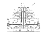
図4は、図2におけるX−X線断面図である。直ケース2の下部には商品が陳列される陳列板19が設けられており、陳列板19の下方空間と棚支柱4の裏側の空間とを連通するダクト20が設けられている。このダクト20内であって陳列板19の下方空間内には、冷却器21とファン22とが設けけられている。これらの冷却器21とファン22とが駆動されることにより、ダクト20内の空気が冷却器21により冷やされて冷気となり、その冷気はファン22によりダクト20内を矢印で示すように送風される。ダクト20内を送風された冷気はダクト20の上部手前側に設けられている冷気吹出口23から下向きに吹き出され、冷気吹出口23から吹き出された冷気は、ダクト20の下部手前側に設けられている冷気吸込口24からダクト20内に吸込まれる。冷気吸込口24からダクト20内に吸込まれた冷気は、冷却器21により再び冷やされてダクト20内を送風される。
FIG. 4 is a cross-sectional view taken along line XX in FIG. A
図6は、図2におけるY−Y線断面図である。アラウンドケース3の下部には陳列板19aが設けられており、陳列板19aの下方空間と棚支柱7aの裏側の空間とを連通するダクト20aが設けられている。このダクト20a内であって陳列板19aの下方空間内には、冷却器21aとファン22aとが設けけられている。これらの冷却器21aとファン22aとが駆動されることにより、ダクト20a内の空気が冷却器21aにより冷やされて冷気となり、その冷気はファン22aによりダクト20a内を矢印で示すように送風される。ダクト20a内を送風された冷気はダクト20aの上部手前側に設けられている冷気吹出口23aから下向きに吹き出され、冷気吹出口23aから吹き出された冷気は、ダクト20aの下部手前側に設けられている冷気吸込口24aからダクト20a内に吸込まれる。冷気吸込口24aからダクト20a内に吸込まれた冷気は、冷却器21aにより再び冷やされてダクト20a内を送風される。
6 is a cross-sectional view taken along line YY in FIG. A
アラウンドケース3に設けられている商品陳列棚8の支持構造について、図2及び図5に基づいて説明する。図2に示すように、棚支柱7にはブラケット12が取付けられ、棚支柱7aにはブラケット12aが取付けられている。そして、これらのブラケット12、12aにおけるスライドレール13が取付けられる部分は平行に対向している。そして、これらのスライドレール13により商品陳列棚8が支持されている。なお、商品陳列棚8は上下に3段設けられており、各商品陳列棚8は同じ支持構造とされている。
A support structure for the
スライドレール13は、固定側レール13aとスライド側レール13bとスライド機構13cとにより構成され、固定側レール13aとスライド側レール13bとがスライド機構13cを介してスライド可能とされている。そして、固定側レール13aがブラケット12、12aに固定され、スライド側レール12bが商品陳列棚8に固定されている。これにより、商品陳列棚8がスライドレール13を介してブラケット12、12aにスライド可能に支持され、商品陳列棚8は棚支柱7、7aに対して接離する方向である前後方向にスライド可能とされている。
The
つぎに、アラウンドケース3に設けられている商品陳列棚8aの支持構造について、図2、図6及び図7に基づいて説明する。図2及び図6に示すように、棚支柱7aには、上下3段に一対ずつのブラケット14とブラケットエンド15との一端が取付けられている。ブラケット14の他端は、図2に示すように、棚支柱7aから離れるにつれてハの字形に拡開している。また、ブラケットエンド15の他端は、ブラケット12aと平行な方向に延出している。そして、これらのブラケット14及びブラケットエンド15の上部に矩形状の固定板16が固定され、固定板16には一対のスライドレール17が平行に取付けられ、これらのスライドレール17を介して商品陳列棚8aが棚支柱7aに対して接離する方向である前後方向にスライド可能に支持されている。
Next, a support structure for the
スライドレール17は、図5に示したスライドレール13と同じ構造であり、図7に示すように、固定側レール17aとスライド側レール17bとスライド機構17cとにより構成され、固定側レール17aとスライド側レール17bとがスライド機構17cを介してスライド可能とされている。そして、固定側レール17aが固定板16に固定され、スライド側レール17bが商品陳列棚8aに固定されている。これにより、商品陳列棚8aがスライドレール17を介してブラケット14及びブラケットエンド15支持され、商品陳列棚8aは棚支柱7aに対して接離する方向である前後方向にスライド可能とされている。
The
このような構成において、商品陳列棚5、8、8aへの商品陳列作業は、商品陳列棚5、8、8aを図3に示す手前側位置にスライドさせた状態で行う。
In such a configuration, the product display work on the
ここで、直ケース2の商品陳列棚5を手前側位置にスライドさせることについて説明する。一対の棚支柱4には、平行に対向する一対のブラケット10が取付けられ、これらのブラケット10に平行に対向するスライドレール11が取付けられている。そして、これらのスライドレール11を介して商品陳列棚5がスライド可能に支持され、商品陳列棚5は棚支柱4に対して接離する方向である前後方向にスライド可能とされている。このため、商品陳列棚5上への商品陳列作業時には、図3の実線又は図4の二点鎖線で示すように、商品陳列棚5を棚支柱4から離れる方向である手前側位置にスライドさせることより、商品陳列作業を行う作業者の手元近くに商品陳列棚5を位置させることができ、商品陳列棚5上への商品陳列作業を容易に行うことができる。
Here, sliding the
つぎに、アラウンドケース3の商品陳列棚8を手前側位置にスライドさせることについて説明する。棚支柱7にはブラケット12が取付けられ、棚支柱7aにブラケット12aが取付けられている。これらのブラケット12、12aは、スライドレール13が取付けられる部分が平行に対向し、ブラケット12、12aに取付けられたスライドレール13は平行に対向している。そして、これらのスライドレール13を介して商品陳列棚8がスライド可能に支持され、商品陳列棚8は棚支柱7、7aに対して接離する方向である前後方向にスライド可能とされている。このため、商品陳列棚8上への商品陳列作業時には、図3の実線で示すように、商品陳列棚8を棚支柱7、7aから離れる方向である手前側位置にスライドさせることより、商品陳列作業を行う作業者の手元近くに商品陳列棚8を位置させることができ、商品陳列棚8上への商品陳列作業を容易に行うことができる。
Next, sliding the
つぎに、アラウンドケース3の商品陳列棚8aを手前側位置にスライドさせることについて説明する。一端が棚支柱7aに取付けられて他端がハの字形に拡開するブラケット14と、一端が棚支柱7aに取付られて他端がブラケット12aと平行な方向に延出するブラケットエンド15とが設けられ、これらのブラケット14とブラケットエンド15との上部に固定板16が固定されている。そして、固定板16に一対のスライドレール17が平行に取付けられ、これらのスライドレール17を介して商品陳列棚8aがスライド可能に支持され、商品陳列棚8aは棚支柱7aに対して接離する方向である前後方向にスライド可能とされている。このため、商品陳列棚8a上への商品陳列作業時には、図3の実線又は図6の二点鎖線で示すように、商品陳列棚8aを棚支柱7aから離れる方向である手前側位置にスライドさせることより、商品陳列作業を行う作業者の手元近くに商品陳列棚8aを位置させることができ、商品陳列棚8a上への商品陳列作業を容易に行うことができる。
Next, sliding the
ここで、ブラケット14及びブラケットエンド15の上部に固定板16が固定され、固定板16には棚支柱7aから離れる方向に延出する一対のスライドレール17が平行に取付けられている。したがって、一対のブラケット14が平行に配置されていなくても、その一対のブラケット14に固定板16を固定し、固定板16に一対のスライドレール17を取付けることにより、一対のスライドレール17を平行に対向させることができるとともに、そのスライドレール17を用いて商品陳列棚8aを棚支柱7aに対して接離する方向である前後方向にスライド可能に支持することができる。
Here, a fixed
また、商品陳列棚5、8、8aが、上下方向に複数段設けられている場合には、商品陳列作業を行う商品陳列棚5、8、8aを棚支柱4、7、7aから離反する方向へスライドさせることにより、スライドさせた商品陳列棚5、8、8aの上方に位置する他の商品陳列棚5、8、8aが商品陳列作業の妨げになることを防止することができ、商品陳列棚5、8、8a上への商品陳列作業を容易に行うことができる。
Further, when the
1 ショーケース
2 直ケース
3 アラウンドケース
4 棚支柱
5 商品陳列棚
6 背面板
7 棚支柱
7a 棚支柱
8 商品陳列棚
8a 商品陳列棚
9 背面板
10 ブラケット
11 スライドレール
12 ブラケット
12a ブラケット
13 スライドレール
13a 固定側レール
13b スライド側レール
13c スライド機構
14 ブラケット
15 ブラケットエンド
16 固定板
17 スライドレール
17a 固定側レール
17b スライド側レール
17c スライド機構
18 ランプ
19 陳列板
20 ダクト
20a ダクト
21 冷却器
21a 冷却器
22 ファン
22a ファン
23 冷気吹出口
23a 冷気吹出口
24 冷気吸込口
24a 冷気吸込口
DESCRIPTION OF
Claims (2)
前記ブラケットの上部に固定された固定板と、
前記固定板に取付けられ、前記棚支柱から離れる方向に延出して平行に対向する一対のスライドレールと、
前記スライドレールを介して前記棚支柱に対して接離する方向にスライド可能に前記ブラケットに支持された商品陳列棚と、
を有することを特徴とするアラウンドケース。 A pair of brackets, one end of which is attached to the shelf column extending in the vertical direction and the other end of which is expanded in a C shape as the other end is separated from the shelf column;
A fixing plate fixed to the upper part of the bracket;
A pair of slide rails attached to the fixed plate and extending in a direction away from the shelf column and facing in parallel;
A merchandise display shelf supported by the bracket so as to be slidable in a direction of coming into contact with and separating from the shelf column via the slide rail;
An around case characterized by comprising:
Priority Applications (1)
| Application Number | Priority Date | Filing Date | Title |
|---|---|---|---|
| JP2016238142A JP2018093902A (en) | 2016-12-08 | 2016-12-08 | Around Case |
Applications Claiming Priority (1)
| Application Number | Priority Date | Filing Date | Title |
|---|---|---|---|
| JP2016238142A JP2018093902A (en) | 2016-12-08 | 2016-12-08 | Around Case |
Publications (1)
| Publication Number | Publication Date |
|---|---|
| JP2018093902A true JP2018093902A (en) | 2018-06-21 |
Family
ID=62632113
Family Applications (1)
| Application Number | Title | Priority Date | Filing Date |
|---|---|---|---|
| JP2016238142A Pending JP2018093902A (en) | 2016-12-08 | 2016-12-08 | Around Case |
Country Status (1)
| Country | Link |
|---|---|
| JP (1) | JP2018093902A (en) |
Citations (6)
| Publication number | Priority date | Publication date | Assignee | Title |
|---|---|---|---|---|
| JPH10148448A (en) * | 1996-11-15 | 1998-06-02 | Nakano Refrigerators Co Ltd | Around-showcase |
| JP2000139638A (en) * | 1998-11-13 | 2000-05-23 | Sanden Corp | Rack structure of show case |
| JP2000316682A (en) * | 1999-05-13 | 2000-11-21 | Okamura Corp | Round shelf board supporting device |
| JP2002045276A (en) * | 2000-08-03 | 2002-02-12 | Sanyo Electric Co Ltd | Showcase |
| JP2008220987A (en) * | 2008-05-12 | 2008-09-25 | Fuji Electric Retail Systems Co Ltd | Showcase |
| JP2014108182A (en) * | 2012-11-30 | 2014-06-12 | Okamura Corp | Open showcase |
-
2016
- 2016-12-08 JP JP2016238142A patent/JP2018093902A/en active Pending
Patent Citations (6)
| Publication number | Priority date | Publication date | Assignee | Title |
|---|---|---|---|---|
| JPH10148448A (en) * | 1996-11-15 | 1998-06-02 | Nakano Refrigerators Co Ltd | Around-showcase |
| JP2000139638A (en) * | 1998-11-13 | 2000-05-23 | Sanden Corp | Rack structure of show case |
| JP2000316682A (en) * | 1999-05-13 | 2000-11-21 | Okamura Corp | Round shelf board supporting device |
| JP2002045276A (en) * | 2000-08-03 | 2002-02-12 | Sanyo Electric Co Ltd | Showcase |
| JP2008220987A (en) * | 2008-05-12 | 2008-09-25 | Fuji Electric Retail Systems Co Ltd | Showcase |
| JP2014108182A (en) * | 2012-11-30 | 2014-06-12 | Okamura Corp | Open showcase |
Similar Documents
| Publication | Publication Date | Title |
|---|---|---|
| CA2831239C (en) | Display system | |
| US20140263128A1 (en) | Convertible gondola shelving | |
| US20150351561A1 (en) | Double end frame | |
| US20130186847A1 (en) | Shelving Systems | |
| JP2018093902A (en) | Around Case | |
| JP4877946B2 (en) | Service counter equipment | |
| JP6692143B2 (en) | Storage box suspension structure | |
| JP6952273B2 (en) | Showcase | |
| JP5986821B2 (en) | Showcase | |
| JP4653433B2 (en) | Product display stand | |
| JP3182957U (en) | Product display shelf | |
| JP2015173902A (en) | Showcase product display shelf support structure | |
| JP3240108U (en) | panel display device | |
| JP3189754U (en) | Product display stand and product display device | |
| JP6624420B2 (en) | Display fixtures | |
| JP3207629U (en) | Product display stand | |
| JP4996396B2 (en) | Showcase shelf structure | |
| JP3212968U (en) | Sales promotion device | |
| JP4236341B2 (en) | Showcase product shelf | |
| JP6891635B2 (en) | Showcase | |
| JP3208171U (en) | Moving mechanism of moving table | |
| JP2949892B2 (en) | Showcase merchandise display shelves | |
| KR101699759B1 (en) | Display stand for arranging merchandise thereon | |
| KR200254015Y1 (en) | Multipurpose exhibition stand | |
| JP2005013402A (en) | Bottle display device and display shelf using it |
Legal Events
| Date | Code | Title | Description |
|---|---|---|---|
| A621 | Written request for application examination |
Free format text: JAPANESE INTERMEDIATE CODE: A621 Effective date: 20191129 |
|
| A977 | Report on retrieval |
Free format text: JAPANESE INTERMEDIATE CODE: A971007 Effective date: 20201019 |
|
| A131 | Notification of reasons for refusal |
Free format text: JAPANESE INTERMEDIATE CODE: A131 Effective date: 20201022 |
|
| A131 | Notification of reasons for refusal |
Free format text: JAPANESE INTERMEDIATE CODE: A131 Effective date: 20210519 |
|
| A02 | Decision of refusal |
Free format text: JAPANESE INTERMEDIATE CODE: A02 Effective date: 20211102 |