JP2018094868A - Inkjet printer and method for cleaning ink head in inkjet printer - Google Patents
Inkjet printer and method for cleaning ink head in inkjet printer Download PDFInfo
- Publication number
- JP2018094868A JP2018094868A JP2016244244A JP2016244244A JP2018094868A JP 2018094868 A JP2018094868 A JP 2018094868A JP 2016244244 A JP2016244244 A JP 2016244244A JP 2016244244 A JP2016244244 A JP 2016244244A JP 2018094868 A JP2018094868 A JP 2018094868A
- Authority
- JP
- Japan
- Prior art keywords
- ink
- ink jet
- head
- pump
- inkjet
- Prior art date
- Legal status (The legal status is an assumption and is not a legal conclusion. Google has not performed a legal analysis and makes no representation as to the accuracy of the status listed.)
- Withdrawn
Links
Images




Landscapes
- Ink Jet (AREA)
Abstract
【課題】インクジェットノズル内部における種類の異なるインクによる混合状態の発生を防止する。【解決手段】上記吸引ポンプにより上記インクジェットノズルから上記インクを吸引した後に、上記キャップ部材による上記開口部の上記封止を解除して、上記クリーニング処理を行うインクジェットプリンタにおいて、上記クリーニング処理において上記吸引ポンプにより上記インクを吸引した後に、上記送液ポンプにより上記インクヘッドへ上記インクを送液させ、上記インクジェットノズル内を大気圧以上の圧力とするポンプ制御手段を有する。【選択図】 図7An object of the present invention is to prevent a mixed state caused by different types of ink inside an inkjet nozzle. In the ink jet printer that performs the cleaning process by releasing the sealing of the opening by the cap member after the ink is sucked from the ink jet nozzle by the suction pump, the suction is performed in the cleaning process. After the ink is sucked by the pump, there is pump control means for feeding the ink to the ink head by the liquid feed pump so that the pressure in the ink jet nozzle is equal to or higher than atmospheric pressure. [Selection] Figure 7
Description
本発明は、インクジェットプリンタおよびインクジェットプリンタにおけるインクヘッドのクリーニング方法に関する。さらに詳細には、本発明は、インクジェット方式によりメディアに向けてインクを吐出する複数のインクジェットノズルを備えたインクヘッドをクリーニングするインクジェットプリンタおよびインクジェットプリンタにおけるインクヘッドのクリーニング方法に関する。 The present invention relates to an inkjet printer and an ink head cleaning method in an inkjet printer. More specifically, the present invention relates to an ink jet printer that cleans an ink head having a plurality of ink jet nozzles that eject ink toward a medium by an ink jet method, and a method for cleaning the ink head in the ink jet printer.
なお、本明細書において「メディア」とは、普通紙などの紙類よりなる各種の記録媒体は勿論のこと、PVC、ポリエステルなどの樹脂材料やアルミ、鉄、木材のような材料などの各種材料が含まれるものとする。 In this specification, the term “media” refers to various recording media such as plain paper and various recording media such as resin materials such as PVC and polyester, and materials such as aluminum, iron, and wood. Is included.
また、本明細書において「インクジェット方式」とは、二値偏向方式あるいは連続偏向方式などの各種の連続方式や、サーマル方式あるいは圧電素子方式などの各種のオンデマンド方式を含む、従来より公知の各種の手法によるインクジェット技術による印刷方法を意味するものとする。 Further, in the present specification, the “inkjet method” means various conventionally known methods, including various continuous methods such as a binary deflection method or a continuous deflection method, and various on-demand methods such as a thermal method or a piezoelectric element method. This means a printing method using an inkjet technique according to the above method.
さらに、本明細書における圧力の表記については、大気圧基準(標準大気圧1atm=0kPa(G))を用いるものとする。従って、「標準大気圧1atm=0kPa(G)」より高い圧力は正圧となり、「標準大気圧1atm=0kPa(G)」より低い圧力は負圧となる。 Furthermore, the atmospheric pressure reference (standard atmospheric pressure 1 atm = 0 kPa (G)) is used for the pressure notation in this specification. Therefore, a pressure higher than “standard atmospheric pressure 1 atm = 0 kPa (G)” is a positive pressure, and a pressure lower than “standard atmospheric pressure 1 atm = 0 kPa (G)” is a negative pressure.
従来より、マイクロコンピューターによって全体の動作を制御され、メディアたる記録紙と対向する面にインクジェット方式により複数の異なる色彩のインクをそれぞれ吐出する複数のインクジェットノズルを備えたインクヘッドに、複数の異なる色彩のインクをそれぞれ供給し、供給された複数の異なる色彩のインクをそれぞれの色彩のインクに対応するするように設定されたインクジェットノズルから記録紙に対して吐出して、当該記録紙上にカラー印刷を行うようにしたインクジェットプリンタが知られている。 Conventionally, a plurality of different colors are applied to an ink head having a plurality of ink jet nozzles that respectively eject a plurality of different colors of ink by an ink jet method on a surface facing a recording paper as a medium, which is controlled by a microcomputer. Ink is supplied to each of the recording papers, and a plurality of supplied inks of different colors are ejected onto the recording paper from ink jet nozzles set to correspond to the inks of the respective colors, and color printing is performed on the recording paper. Inkjet printers are known that perform.
こうしたインクジェットプリンタのインクヘッドにおいては、インクジェットノズル内に気泡が混入したり、あるいは、インクジェットノズル内でインクが凝集したりすると、インクジェットノズルに目詰まりなどが発生してインクの吐出不良が生じる。 In the ink head of such an ink jet printer, when bubbles are mixed in the ink jet nozzle or the ink is aggregated in the ink jet nozzle, the ink jet nozzle is clogged and the ink discharge is defective.
インクヘッドのインクジェットノズルにおけるインクの吐出不良が生じた場合には、以下に説明するインクヘッドのインクジェットノズルをクリーニングするクリーニング処理が実行されていた。 When ink ejection failure occurs in the ink jet nozzles of the ink head, a cleaning process for cleaning the ink jet nozzles of the ink head described below has been performed.
このクリーニング処理とは、以下の処理を順次行うことを意味する。即ち、まず、キャップ装置のキャップ部材により、インクヘッドのインクジェットノズルが形成された面(本明細書においては、「インクヘッドのインクジェットノズルが形成された面」を「インクジェットノズル面」と適宜に称する。)をキャッピング(封止)する。次に、この状態で吸引ポンプを作動して、キャッピングされたインクジェットノズル面を負圧にする。これにより、インクヘッド内のインクは、インクジェットノズルからキャップ部材側に強制的に吸引され、インクジェットノズル内の気泡やインクの凝集を解消する。その後に、キャップ部材によるインクヘッドのキャッピングを解除して、インクヘッドをキャップ装置からワイパー装置へと移動し、ワイパー装置のワイパーブレードによりインクジェットノズル面をワイピングする。 This cleaning process means that the following processes are sequentially performed. That is, first, the surface on which the ink jet nozzle of the ink head is formed by the cap member of the cap device (in this specification, the “surface on which the ink jet nozzle of the ink head is formed” is appropriately referred to as “ink jet nozzle surface”. .) Is capped (sealed). Next, in this state, the suction pump is operated to make the capped inkjet nozzle surface have a negative pressure. As a result, the ink in the ink head is forcibly sucked from the ink jet nozzle toward the cap member, thereby eliminating bubbles and ink aggregation in the ink jet nozzle. Thereafter, the capping of the ink head by the cap member is released, the ink head is moved from the cap device to the wiper device, and the inkjet nozzle surface is wiped by the wiper blade of the wiper device.
ところで、例えば、特許第5980390号公報に開示されたインクジェットプリンタなどは、インクを貯留するインクカートリッジと、インクを吐出するインクジェットノズルを備えたインクヘッドと、インクカートリッジからインクヘッドに向けてインクを送液する加圧ポンプ(送液ポンプ)と、インクカートリッジと加圧ポンプとを連通するインク経路に設けられてインクヘッドのインクジェットノズル内のインクを負圧の状態に維持する圧力制御弁と、加圧ポンプの作動と停止を制御するマイクロコンピューターとを備えている。圧力制御弁は電気的に制御されておらず、マイクロコンピューターの制御により加圧ポンプが停止しているときにはインク経路を閉鎖する。 Incidentally, for example, an inkjet printer disclosed in Japanese Patent No. 5980390 discloses an ink cartridge that stores ink, an ink head that includes an inkjet nozzle that discharges ink, and an ink cartridge that sends ink from the ink cartridge toward the ink head. A pressure control valve for supplying liquid, a pressure control valve provided in an ink path communicating with the ink cartridge and the pressure pump, and maintaining the ink in the ink jet nozzle of the ink head in a negative pressure state; It has a microcomputer that controls the operation and stop of the pressure pump. The pressure control valve is not electrically controlled, and closes the ink path when the pressurizing pump is stopped under the control of the microcomputer.
上記した構成を備えたインクジェットプリンタにおいては、圧力制御弁と加圧ポンプとの協働により、インクヘッドのインクジェットノズルからインクを吐出していないときは、インクヘッドのインクジェットノズルの内部の圧力が常に負圧状態となるように維持されている。こうしたインクジェットプリンタにおいては、インクヘッドのインクジェットノズルからインクを吐出していないときは、インクヘッドにおけるインクジェットノズルの内部が常に負圧状態に維持されているため、クリーニング処理におけるインクヘッドからのインクの吸引後にワイパーブレードによりワイピングするまでの間で、インクジェットノズル面に付着したインクがインクジェットノズル内部に逆流してしまう逆流現象が発生していた。 In the ink jet printer having the above-described configuration, the pressure inside the ink jet nozzle of the ink head is always maintained when the ink is not ejected from the ink jet nozzle of the ink head by the cooperation of the pressure control valve and the pressure pump. The negative pressure is maintained. In such an ink jet printer, when ink is not ejected from the ink jet nozzles of the ink head, the inside of the ink jet nozzles of the ink head is always maintained in a negative pressure state, so that ink is sucked from the ink head in the cleaning process. Until the wiping with the wiper blade was performed later, a back flow phenomenon occurred in which the ink adhered to the ink jet nozzle surface flowed back into the ink jet nozzle.
インクジェットノズルが種々の色彩のインクやクリアーインクなどのような異なる種類のインクを吐出するように構成されているインクヘッドにおいて上記した逆流現象が発生すると、インクジェットノズルが吐出する種類のインクとは異なる種類のインクが当該インクジェットノズル内部に逆流してしまうということが発生していた。インクジェットノズルが吐出する種類とは異なる種類のインクが当該インクジェットノズル内部に逆流すると、当該インクヘッドのインクジェットノズル内部で種類の異なるインクによる混合が生じてしまい、そのままの状態で印刷を行うと印刷品質が劣化する。 When the above-described reverse flow phenomenon occurs in an ink head in which an inkjet nozzle is configured to eject different types of ink, such as ink of various colors or clear ink, it is different from the type of ink ejected by the inkjet nozzle. It has occurred that various types of ink flow back into the inkjet nozzle. When ink of a different type from the type ejected by the ink jet nozzle flows back into the ink jet nozzle, mixing with different types of ink occurs inside the ink jet nozzle of the ink head. Deteriorates.
このため、従来のインクジェットプリンタにおいては、上記したインクジェットノズル内部における種類の異なるインクの混合による印刷品質の劣化を防止するために、クリーニング処理後においては、印刷を開始する前にインクジェットノズルからインクを吐出するフラッシングをかなり多めにおこなって、インクジェットノズル内部での種類の異なるインクによる混合状態を解消するようにしていた。 For this reason, in the conventional ink jet printer, in order to prevent the deterioration of the print quality due to the mixing of different types of ink inside the ink jet nozzle described above, after the cleaning process, the ink is ejected from the ink jet nozzle before starting the printing. A considerable amount of flushing was performed to eliminate the mixed state of different types of ink inside the inkjet nozzle.
このため、従来のインクジェットプリンタにおいては、印刷を開始する前にインクジェットノズルからインクを吐出するフラッシングによるインクの消費量が多くなるという問題点があった。 For this reason, the conventional ink jet printer has a problem in that the amount of ink consumed by flushing that ejects ink from the ink jet nozzles before starting printing increases.
本発明は、従来の技術における上記したような問題点に鑑みてなされたものであり、その目的とするところは、インクジェットノズル内部における種類の異なるインクによる混合状態の発生を防止して、こうした混合状態を解消するために消費するインクの消費量を削減することを可能にしたインクジェットプリンタおよびインクジェットプリンタにおけるインクヘッドのクリーニング方法を提供するものである。 The present invention has been made in view of the above-described problems in the prior art, and an object of the present invention is to prevent the occurrence of a mixed state due to different types of ink inside the inkjet nozzle, and to perform such mixing. The present invention provides an ink jet printer and an ink head cleaning method in an ink jet printer that can reduce the amount of ink consumed to eliminate the state.
上記目的を達成するために、本発明は、クリーニング処理において、インクヘッドのインクジェットノズルからインクを吸引するためにインクヘッドのインクジェットノズルが形成されたインクジェットノズル面を負圧にするが、インクヘッドのインクジェットノズル面を負圧にしてインクジェットノズルからのインクの吸引の終了後に、インクヘッドのインクジェットノズル内の圧力を一旦大気圧もしくは正圧にする。なお、正圧の際には、若干の正圧とすることが好ましい。これにより、インクジェットノズル面に付着したインクがインクジェットノズル内部に逆流してしまうことが防止され、インクヘッドのインクジェットノズル内部における異なる種類のインクによる混合状態の発生が防止される。 In order to achieve the above object, according to the present invention, in the cleaning process, in order to suck ink from the ink jet nozzles of the ink head, the ink jet nozzle surface on which the ink jet nozzles of the ink head are formed has a negative pressure. After the suction of the ink from the ink jet nozzle is completed by setting the ink jet nozzle surface to a negative pressure, the pressure in the ink jet nozzle of the ink head is once set to atmospheric pressure or positive pressure. In addition, in the case of a positive pressure, it is preferable to set it as a slight positive pressure. This prevents ink adhering to the ink jet nozzle surface from flowing back into the ink jet nozzle and prevents the mixed state of different types of ink inside the ink jet nozzle of the ink head.
本発明によれば、インクジェットノズル内部における異なる種類のインクによる混合状態の発生が防止されるので、クリーニング処理後において、印刷を開始する前にインクジェットノズルからインクを吐出するフラッシングにより上記した混合状態を解消する必要がなく、上記した印刷開始前のフラッシングによるインクの消費量を削減することができる。 According to the present invention, since the mixed state due to different types of inks inside the inkjet nozzle is prevented, the mixed state described above is performed by flushing the ink from the inkjet nozzle before starting printing after the cleaning process. There is no need to eliminate the ink consumption, and it is possible to reduce the ink consumption due to the flushing before the start of printing.
即ち、本発明によるインクジェットプリンタは、種類の異なるインクを吐出する複数のインクジェットノズルを形成したインクヘッドと、上記インクヘッドへ上記インクを送液する送液ポンプと、上記インクジェットノズルの開口部を封止するキャップ部材と、上記インクジェットノズルから上記インクを吸引する吸引ポンプと、上記インクジェットノズルの開口部が位置するインクジェットノズル面をワイパーブレードでクリーニング処理するワイパー装置とを有し、上記吸引ポンプにより上記インクジェットノズルから上記インクを吸引した後に、上記キャップ部材による上記開口部の上記封止を解除して、上記クリーニング処理を行うインクジェットプリンタにおいて、上記クリーニング処理において上記吸引ポンプにより上記インクを吸引した後に、上記送液ポンプにより上記インクヘッドへ上記インクを送液させ、上記インクジェットノズル内を大気圧以上の圧力とするポンプ制御手段とを有するようにしたものである。 That is, an ink jet printer according to the present invention seals an ink head in which a plurality of ink jet nozzles for discharging different types of ink, a liquid feed pump for feeding the ink to the ink head, and an opening of the ink jet nozzle. A cap member that stops, a suction pump that sucks the ink from the inkjet nozzle, and a wiper device that cleans the inkjet nozzle surface on which the opening of the inkjet nozzle is located with a wiper blade. In the ink jet printer that performs the cleaning process by releasing the sealing of the opening by the cap member after the ink is sucked from the ink jet nozzle, the ink is discharged by the suction pump in the cleaning process. After suction, by the liquid feeding pump to feeding the ink to the ink head, in which to have a pump control means for the inside the ink jet nozzle and above atmospheric pressure.
また、本発明によるインクジェットプリンタは、上記した本発明によるインクジェットプリンタにおいて、上記大気圧以上の圧力は、0〜1kPa(G)であるようにしたものである。 The ink jet printer according to the present invention is the ink jet printer according to the present invention described above, wherein the pressure above the atmospheric pressure is 0 to 1 kPa (G).
また、本発明によるインクジェットプリンタは、上記した本発明によるインクジェットプリンタにおいて、上記種類の異なるインクは、色彩の異なるインクであるようにしたものである。 The ink jet printer according to the present invention is the ink jet printer according to the present invention described above, wherein the different types of inks are inks having different colors.
また、本発明によるインクジェットプリンタにおけるインクヘッドのクリーニング方法は、種類の異なるインクを吐出する複数のインクジェットノズルを形成したインクヘッドと、上記インクヘッドへ上記インクを送液する送液ポンプと、上記インクジェットノズルの開口部を封止するキャップ部材と、上記インクジェットノズルから上記インクを吸引する吸引ポンプと、上記インクジェットノズルの開口部が位置するインクジェットノズル面をワイパーブレードでクリーニング処理するワイパー装置とを有するインクジェットプリンタにおけるインクヘッドのクリーニング方法であって、上記吸引ポンプにより上記インクジェットノズルから上記インクを吸引した後に、上記キャップ部材による上記開口部の上記封止を解除して、上記クリーニング処理を行うインクジェットプリンタのクリーニング方法において、上記クリーニング処理において上記吸引ポンプにより上記インクを吸引した後に、上記送液ポンプにより上記インクヘッドへ上記インクを送液させ、上記インクジェットノズル内を大気圧以上の圧力とするようにしたものである。 The ink head cleaning method in the ink jet printer according to the present invention includes an ink head having a plurality of ink jet nozzles for discharging different types of ink, a liquid feed pump for feeding the ink to the ink head, and the ink jet. Inkjet having cap member for sealing nozzle opening, suction pump for sucking ink from inkjet nozzle, and wiper device for cleaning inkjet nozzle surface on which inkjet nozzle opening is located with wiper blade A method for cleaning an ink head in a printer, wherein after the ink is sucked from the inkjet nozzle by the suction pump, the sealing of the opening by the cap member is released, and the cleaning is performed. In the cleaning method of an ink jet printer that performs a cleaning process, after the ink is sucked by the suction pump in the cleaning process, the ink is fed to the ink head by the liquid feed pump, and the inside of the ink jet nozzle is at atmospheric pressure or higher. The pressure is set as follows.
また、本発明によるインクジェットプリンタにおけるインクヘッドのクリーニング方法は、本発明によるインクジェットプリンタにおけるインクヘッドのクリーニング方法において、上記大気圧以上の圧力は、0〜1kPa(G)であるようにしたものである。 The ink head cleaning method in the ink jet printer according to the present invention is the ink head cleaning method in the ink jet printer according to the present invention, wherein the pressure above the atmospheric pressure is 0 to 1 kPa (G). .
また、本発明によるインクジェットプリンタにおけるインクヘッドのクリーニング方法は、本発明によるインクジェットプリンタにおけるインクヘッドのクリーニング方法において、上記種類の異なるインクは、色彩の異なるインクであるようにしたものである。 The ink head cleaning method in the ink jet printer according to the present invention is the ink head cleaning method in the ink jet printer according to the present invention, wherein the different types of ink are inks of different colors.
本発明は、以上説明したように構成されているので、インクジェットノズル内部における種類の異なるインクによる混合状態の発生を防止することができ、こうした混合状態を解消するために消費するインクの消費量を削減することが可能になるという優れた効果を奏するものである。 Since the present invention is configured as described above, it is possible to prevent the occurrence of a mixed state due to different types of ink inside the inkjet nozzle, and to reduce the amount of ink consumed to eliminate such a mixed state. It has an excellent effect that it can be reduced.
以下、添付の図面を参照しながら、本発明によるインクジェットプリンタおよびインクジェットプリンタにおけるインクヘッドのクリーニング方法の実施の形態の一例を詳細に説明するものとする。 Hereinafter, an example of an embodiment of an ink jet printer and an ink head cleaning method in the ink jet printer according to the present invention will be described in detail with reference to the accompanying drawings.
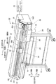
図1には、本発明によるインクジェットプリンタの実施の形態の一例を示す概略構成斜視説明図が示されている。 FIG. 1 is a perspective view of a schematic configuration showing an example of an embodiment of an ink jet printer according to the present invention.
このインクジェットプリンタ10は、基台部材12に支持され主走査方向に延長して配設された固定系のベース部材14を備えている。ベース部材14の左右両端には側方部材16L、16Rが配設され、側方部材16R側には側方ユニット18が配設されている。
The
インクジェットプリンタ10は、左右2つの側方部材16L、16Rを連結する中央壁20を備え、中央壁20の壁面には主走査方向に延長してガイドレール22が配設されている。
The
符号24は、中央壁20の壁面に平行して主走査方向に移動自在に配設されたワイヤーである。キャリッジ26は、ワイヤー24に固定的に配設されるとともにガイドレール22に摺動自在に装着されている。キャリッジ26には、ベース部材14上に位置するメディアたる記録紙28と対向するようにしてインクヘッド30が搭載されてるとともに、インクヘッド30と接続されたダンパー装置32が搭載されている。インクヘッド30には、複数の異なる色彩のインクをそれぞれ吐出する複数のインクジェットノズル(図示せず。)が形成されている。
なお、こうしたインクジェットプリンタ10の全体の動作は、マイクロコンピューター34によって制御されている。
The overall operation of the
また、インクジェットプリンタ10においては、上記したようにメディアとして記録紙28を用いるものとする。この記録紙28は、給紙装置(図示せず。)によってベース部材14上に供給され、幅方向たる主走査方向において所定の長さを有するとともに、主走査方向と直交する方向、即ち、記録紙28の長手方向に搬送される。なお、主走査方向と直交する方向、即ち、記録紙28の搬送方向かつ記録紙28の長手方向を「副走査方向」と称する。
In the
そして、このインクジェットプリンタ10においては、マイクロコンピューター34の制御に従って記録紙28上に印刷が行われる。
In the
即ち、マイクロコンピューター34の制御に従って、ワイヤー24の巻き取りによりワイヤー24が移動すると、このワイヤー24の移動に伴って、キャリッジ26が主走査方向における行き方向(往路)および帰り方向(復路)に往復移動する。これにより、キャリッジ26に搭載されたダンパー装置32およびインクヘッド30が、給紙装置によってベース部材14上に供給された記録紙28上を主走査方向における行き方向(往路)および帰り方向(復路)に一体的に往復移動し、記録紙28上に印刷が行われる。
That is, when the
インクジェットプリンタ10においては、ベース部材14に廃液タンク42が配設されており、側方ユニット18に着脱可能に配設されるインクカートリッジ36から廃液タンクインク42へ至るインク経路100が形成されている(図2を参照する。)。なお、インクカートリッジ36としては、それぞれ異なる色彩のインクを貯留した複数のインクカートリッジ36が配設されている。
In the
インクジェットプリンタ10には、インクヘッド30のインクジェットノズル面30aに設けられたインクジェットノズルの開口部に対してキャッピングするキャップ装置38が設けられている。また、インクジェットプリンタ10には、インクヘッド30のインクジェットノズル面30aをワイパーブレード(図示せず。)でワイピングするワイパー装置39が設けられている。
The
なお、符号40は作業者がインクジェットプリンタ10の動作を制御するための操作子を備えた操作パネルである。操作パネル40には、インクジェットプリンタ10の動作状態を表示するための表示装置40aが設けられている。
Reference numeral 40 denotes an operation panel provided with an operator for the operator to control the operation of the
ここで、図2には、図1に示すインクジェットプリンタ10におけるインクカートリッジ36から廃液タンクインク42へ至るインク経路100を模式的に示す構成説明図が示されている。なお、図2においては、説明を簡素化して本発明の理解を容易にするために、上流側のインクカートリッジ36から下流側のインクヘッド30のインクジェットノズルに至るまでの経路については、1色のインクに関するインク経路を示している。複数の色彩のインクを用いる場合には、上流側のインクカートリッジ36から下流側のインクヘッド30のインクジェットノズルに至るまでの経路が各色分設けられることになる。
Here, FIG. 2 is an explanatory diagram schematically showing an
この図2に示すインク経路100は、一方の端部102aにインクカートリッジ36と連通するように接続されるとともに他方の端部102bにコネクタ104の一方の端部104aが連通するように接続された可撓性のインク供給チューブ102を備えている。インク供給チューブ102の端部102bとコネクタ104の端部104aとは、着脱自在に接続されている。
The
インクカートリッジ36はインクヘッド30へ供給するためのインクを貯留しており、インクカートリッジ36内に貯留されたインクの量を検知するセンサー(図示せず。)が設けられている。
The
コネクタ104は、屈曲可能な蛇腹状部位を備えた中空パイプ形状を備え、その他方の端部104bにはダンパー装置32が接続されている。
The
ダンパー装置32はインクヘッド30とともにキャリッジ26に搭載されており、コネクタ104を通過したインクを一時的に貯留する貯留室(図示せず。)を備えている。このダンパー装置32により、キャリッジ26が記録紙28に対して往復動する際におけるインク経路100内のインクの圧力変動を吸収している。また、ダンパー装置32は、ダンパー装置32内に貯留されたインクの量を検出するインク貯留量検出装置を備えている。
The
ダンパー装置32のインク貯留量検出装置は、例えば、ダンパー装置32の貯留室に貯留されたインクの量が所定量以下であるか否かを検出するものである。ここで、ダンパー装置32の貯留室に貯留可能なインクの量を、例えば、6ccとすると、所定量は、例えば、3〜4ccである。ダンパー装置32のインク貯留量検出装置が、貯留室に貯留されたインクの量が所定量以下となったことを検出すると、マイクロコンピューター34の自動制御により加圧ポンプ101(後述する。)を作動して、加圧ポンプ101から予め設定された量のインクをダンパー装置32の貯留室に加圧して送液する。
The ink storage amount detection device of the
こうしたインク貯留量検出装置は、例えば、特許第5980390号公報などに開示された公知の技術であるため、その詳細な構成ならびに作用の説明は省略する。 Since such an ink storage amount detection device is a known technique disclosed in, for example, Japanese Patent No. 5980390, the detailed configuration and description of the operation are omitted.
ダンパー装置32には、ダンパー装置32の貯留室と連通するインクジェットノズルを備えたインクヘッド30が接続されており、インクカートリッジ36に貯留されたインクは、ダンパー装置32を介してインクヘッド30へ供給される。インクヘッド30に供給されたインクは、インクジェットノズル面30aに開口部が形成されたインクヘッドノズルから吐出される。インクヘッド30のインクジェットノズルは、後に詳述するように、圧力制御弁108(後述する。)と加圧ポンプ101との協働により、インクを吐出していないときは内部の圧力が常に負圧状態となるように維持されている。
An
また、インク供給チューブ102においては、一方の端部102aと圧力制御弁108との間にバルブ弁106が設けられている。バルブ弁106は、例えば、ソレノイドバルブにより構成されている。バルブ弁106は、バルブ弁106を開放してインクカートリッジ36からインクヘッド30へのインクの供給を許容したり、バルブ弁106を閉鎖してインクカートリッジ36からインクヘッド30へのインクの供給を停止したりを選択的に制御することができる。
In the
インク供給チューブ102においては、圧力制御弁108と加圧ポンプ101とが、バルブ弁106とダンパー装置32との間に配置されている。圧力制御弁108が上流側に配置され、加圧ポンプ101が下流側に配置される。
In the
圧力制御弁108は、インクヘッド30のインクジェットノズル内のインクを負圧の状態に維持する。圧力制御弁108は、電気的に制御されておらず、マイクロコンピューター34の制御により加圧ポンプ101が停止しているときは、インク供給チューブ102を閉じてインク経路100を閉鎖する。
The
加圧ポンプ101は、マイクロコンピューター34の自動制御によって作動すると、インクカートリッジ36からダンパー装置32へ向けてインクを加圧して送液し、マイクロコンピューター34の自動制御によって作動を停止すると、インクカートリッジ36からダンパー装置32へ向けてのインクの送液を停止する。
When the
インク供給チューブ102に圧力制御弁108と供給ポンプ101とを設けることにより、加圧ポンプ101が停止しているときには、圧力制御弁108によってインク供給チューブ102を閉じてインク経路100が閉鎖されている。これにより、インクヘッド30のインクジェットノズルがインクを吐出していないときは、インクヘッド30のインクジェットノズル内部の圧力が常に負圧状態となるように維持される。従って、インクジェットプリンタ10の不使用時には、インクヘッド30からのインク漏れを的確に防止することができる。また、インクカートリッジ36をインクヘッド30よりも高い位置に配置することが可能となり、高さ方向の設計(レイアウト)の自由度を高めることができる。さらに、この構成では、インクジェットプリンタ10の不使用時に、インク供給チューブ102の一部を押しつぶし続ける必要が無く、インクジェットプリンタ10の使用時には安定してインクをインクヘッド30に供給することができる。
By providing the
上記した圧力制御弁108と加圧ポンプ101とは、例えば、特許第5980390号公報などに開示されている従来より公知の技術であるので、その詳細な構成ならびに作用の説明は省略する。
Since the
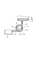
なお、本実施の形態においては、加圧ポンプ101としては、コロを回転することによりチューブを潰してインクを加圧して送液する、従来より公知のチューブポンプを用いるものとする。図3には、加圧ポンプ101の構成の一例を示す構成説明図が示されている。加圧ポンプ101は、インク供給チューブ102におけるバルブ弁106とコネクタ104との間に設けられている。チューブポンプ自体は従来より公知の技術であるので、加圧ポンプ101についての詳細な説明は省略するが、加圧ポンプ101はその内部に、中心部C1を中心として矢印A方向に回転する円形台座101aと、円形台座101aの円周部にそれぞれ配設されたコロ101b、101cとを有している。コロ101b、101cとは、中心部C1を対称点として点対称位置に配置されている。加圧ポンプ101においては、円形台座101aの中心部C1を中心として矢印A方向に回転することにより、コロ101b、101cが円形台座101aの円周上を矢印A方向に回転移動することになり、これにより内部のチューブ101dの押圧状態を変化させ、バルブ弁106側からコネクタ104側へインクを送液する。この加圧ポンプ101においては、円形台座101aが中心部C1を中心として回転角45度で回転するのを1単位の回転量(作動量)、即ち、単位回転量(単位作動量)として設定されている。
In the present embodiment, as the pressurizing
加圧ポンプ101は、中心部C1を中心として円形台座101aを回転することによるコロ101b、101cの回転の回転速度を切り替えることができるとともに、コロの回転角についても任意の角度に設定することができる。
The pressurizing
また、インクジェットプリンタにおいては、上記において説明したように、インクヘッド30のインクジェットノズル面30aに形成されたインクジェットノズル周りをキャッピングするキャップ装置38が設けられている。
Further, as described above, the ink jet printer is provided with the
キャップ装置38は、インクヘッド30のインクジェットノズル面30aに形成されたインクジェットノズルの開口部を封止するキャップ部材112と、インク経路100内のインクを吸引可能な吸引ポンプ114とを有して構成されている。吸引ポンプ114は、インクヘッド30のインクジェットノズル面30aに形成されたインクジェットノズルの開口部を封止したキャップ部材112に負圧を供給し、インク供給経路100内のインクを吸引する。
The
符号116は廃液チューブであり、一方の端部116aをキャップ部材112に接続するとともに他方の端部116bを廃液タンク118に接続している。吸引ポンプ114は、廃液チューブ116の一方の端部116aと他方の端部116bとの間に設けられている。
吸引ポンプ114としては、従来より公知の種々の構成のものを用いることが可能であり、例えば、チューブポンプやトロコイドポンプなどを用いることができ、インクの吸引速度を可変することができる。
As the
ここで、チューブポンプやトロコイドポンプは、ポンプ内のコロを移動したり歯車を回転させたりして吸引力を発生させている状態と、所定の位置でポンプ内のコロの移動を停止したり歯車の回転を停止して吸引力が解除されて外気に開放された状態と、所定の位置でポンプ内のコロの移動を停止したり歯車の回転を停止して吸引力が解除されて外気に対して閉鎖された状態とを選択的に制御可能なポンプである。 Here, the tube pump and the trochoid pump stop the movement of the roller in the pump at a predetermined position and the state where the suction force is generated by moving the roller in the pump or rotating the gear. When the suction force is released and the air is released to the outside air, the roller movement in the pump is stopped at a predetermined position, or the gear rotation is stopped and the suction force is released to the outside air. The pump can selectively control the closed state.
具体的には、吸引ポンプ114としては、図4に示すように、例えば、特許第4857798号などに開示されたチューブポンプと同様な構成のチューブポンプを用いることができる。
Specifically, as the
この図4に示す吸引ポンプ114は、その内部に中心部C2を中心として矢印B方向に回転する円形台座114aと、円形台座114aの円周部にそれぞれ配設されたコロ114b、114cとを有している。コロ114b、114cとは、中心部C2を対称点として点対称位置に配置されている。吸引ポンプ114においては、円形台座114aの中心部C2を中心として矢印B方向に回転することにより、コロ114b、114cが円形台座114aの円周上を矢印B方向に回転移動することになり、これにより内部のチューブ114dの押圧状態を変化させ、キャップ部材112に負圧を供給して吸引力を発生させている状態と、所定の位置でコロ114b、114cの移動を停止して吸引力が解除されて外気に開放された状態と、所定の位置でコロ114b、114cの移動を停止して吸引力が解除されて外気に対して閉鎖された状態とを選択することができる。吸引ポンプ114においては、中心部C2を中心として円形台座114aを回転することによるコロ114b、114cの回転の回転速度を変化して、コロ114b、114cの移動速度を変化させることにより、インクの吸引速度を変化させることができる。
The
なお、吸引ポンプ114は、本実施の形態においては、吸引速度が低速ではインクを1秒当たり0.05cc吸引し、吸引速度が中速ではインクを1秒当たり0.075cc吸引し、吸引速度が高速ではインクを1秒当たり0.1cc吸引するものとする。このインクを1秒当たり0.1cc吸引する吸引速度が、吸引ポンプ114が適正に動作する吸引速度の最高速度となる。
In this embodiment, the
図5(a)(b)(c)には、インクヘッド30のインクジェットノズルが形成されたインクジェットノズル面30aとキャップ部材112との位置関係が模式的に示されている。
5A, 5B, and 5C schematically show the positional relationship between the ink
図5(a)は、インクヘッド30がキャップ装置38のキャップ部材112によりインクジェット面30aをキャッピングされているキャッピング位置を示す。図5(b)は、インクヘッド30とキャップ部材112とが所定の距離離隔した待機位置を示す。図5(c)は、インクヘッド30からキャップ部材112が若干の間隙G(例えば、0.5mm)をあけて離隔したキャップ内フラッシング位置(CAP内FL位置)を示す。
FIG. 5A shows a capping position where the
次に、図6には、インクジェットプリンタ10におけるマイクロコンピューター34の本発明の実施に関連する機能的構成をあらわすブロック構成説明図が示されている。
Next, FIG. 6 is a block diagram illustrating a functional configuration related to the implementation of the present invention of the
マイクロコンピューター34は、制御部202と、記憶部204と、加圧ポンプ制御部206とを有して構築される。
The
制御部202は、インクジェットプリンタ10により実行される印刷処理や後述するクリーニング処理(図7を参照する。)などの各種の処理の実行を含む全体の処理の制御を行う。
The
記憶部204は、印刷処理やクリーニング処理などの各種の処理において用いる各種の情報を記憶する。
The
加圧ポンプ制御部206は、クリーニング処理中における加圧ポンプ101の作動と停止とを制御する。即ち、加圧ポンプ101は、マイクロコンピューター34(制御部202)によって、ダンパー装置32のインク貯留量検出装置が貯留室に貯留されたインクの量が所定量以下となったことを検出すると、予め設定された量のインクをダンパー装置32の貯留室に加圧して送液するように自動的に制御されている。加圧ポンプ制御部206は、クリーニング処理において、こうしたマイクロコンピューター34(制御部202)による加圧ポンプ101の自動制御を停止させ、自動制御の停止中において予め設定された条件で加圧ポンプ101を作動する。そして、この作動を完了すると、マイクロコンピューター34(制御部202)による自動制御を再開する。
The pressurization
以上の構成において、マイクロコンピューター34の制御により、バルブ弁106を開いてインクカートリッジ36からインク供給チューブ102へインクを供給しながら、インクヘッド30のインクヘッドジェットノズルから記録紙28に対してインクを吐出し、記憶紙28へ印刷する。
In the above configuration, under the control of the
ここで、インクヘッドの30のインジェットヘッドノズルからインクが吐出され、これに伴いインクがダンパー装置32からインクヘッド30へ排出される。ダンパー装置32のインク貯留量検出装置は、ダンパー装置32に貯留されているインクの量を検出する。
Here, ink is ejected from the 30 jet head nozzles of the ink head, and the ink is discharged from the
マイクロコンピューター34の制御部202は、ダンパー装置32に貯留されているインクの量が予め設定された量以下になったことをインク貯留量検出装置が検出すると、加圧ポンプ101を作動し予め設定された量のインクをダンパー装置32の貯留室へ送液する。
When the ink storage amount detection device detects that the amount of ink stored in the
次に、図7に示すインクジェットプリンタ10が実行するクリーニング処理ルーチンのフローチャートを参照しながら、インクジェットプリンタ10の動作について説明する。
Next, the operation of the
インクヘッド30が、キャップ装置38のキャップ部材112によりインクジェット面30aをキャッピングされているキャッピング位置(図5(a)に示す位置)にあるとき、ユーザーによる操作パネル40の操作によりクリーニング処理の実行が指示されると、図7に示すクリーニング処理ルーチンが起動する。
When the
以下に説明するクリーニング処理ルーチンにおいては、インクヘッド30とキャップ部材112およびワイパー装置39との位置関係を変化させる動作を行う。この位置関係を変化させる動作については、単にインクヘッド30とキャップ部材112およびワイパー装置39との位置関係が相対的に変化すればよいものであり、インクヘッド30とキャップ部材112とのいずれか一方あるいは双方、または、インクヘッド30とワイパー装置39とのいずれか一方あるいは双方を移動させればよい。こうした、インクヘッド30とキャップ部材112およびワイパー装置39との位置関係を相対的に変化する技術については従来より公知の技術であるので、その詳細な構成ならびに作用の説明は省略する。
In the cleaning processing routine described below, an operation of changing the positional relationship between the
なお、下記の説明においては、説明を簡略化して本発明の理解を容易にするために、インクヘッド30を移動することにより、インクヘッド30とキャップ部材112およびワイパー装置39との位置関係を相対的に変化するものとして説明する。
In the following description, in order to simplify the description and facilitate understanding of the present invention, the positional relationship between the
クリーニング処理ルーチンが起動すると、インクヘッド30を低速(例えば、1cm/sec)で移動して、キャップ部材112によるキャッピングを解除してキャップ部材112を開放し(ステップS702)、インクヘッド30とキャップ部材112とが所定の距離離隔した待機位置(図7(b)に示す位置)へインクヘッド30を移動する(ステップS704)。
When the cleaning processing routine is started, the
ステップS704の処理を終了すると、ステップS706の処理へ進み、マイクロコンピューター34の制御部202の制御により、吸引ポンプ114を高速で0.914秒間正転(なお、「正転」とは、吸引ポンプ114においてインクを吸引する回転方向である。)させて、吸引ポンプ114のコロ114b、114cの位置を吸引開始位置へ移動する。
When the process of step S704 is completed, the process proceeds to the process of step S706. Under the control of the
ステップS706の処理を終了すると、ステップS708の処理へ進み、インクヘッド30を低速でキャッピング位置へ移動して、キャップ部材112によりインクジェット面30aをキャッピングする。
When the process of step S706 is completed, the process proceeds to the process of step S708, the
ステップS708の処理を終了すると、ステップS710の処理へ進み、マイクロコンピューター34の吸引ポンプ制御部208の制御により、吸引ポンプ114を中速で13.7秒間正転させて、インクヘッド30のインクジェットノズルからインクを吸引する。吸引ポンプ114を中速で13.7秒間正転させてインクを吸引する吸引量は、ダンパー装置32のインク貯留量検出装置が、ダンパー装置32の貯留室に貯留されたインクの量が所定量以下であることを検出可能な吸引量である。
When the process of step S708 is completed, the process proceeds to the process of step S710. Under the control of the suction pump control unit 208 of the
ステップS710の処理を終了すると、ステップS712の処理へ進み、11秒間処理を休止する。この休止時間とは、インクヘッド30上流部のインクがキャップ部材112より下に流れ、インクヘッド30上の負圧とインクヘッド30下の負圧が均一になるのを待つ時間である。ここでの負圧は、−0.5〜−1.7kPa(G)程度である。
When the process of step S710 ends, the process proceeds to step S712, and the process is paused for 11 seconds. The pause time is a time for waiting for the ink in the upstream portion of the
ステップS712の処理を終了すると、ステップS714の処理へ進み、加圧ポンプ制御部206の制御により、制御部202による加圧ポンプ101の自動制御を停止させる。これにより加圧ポンプ101の作動は停止し、圧力制御弁108はインク供給チューブ102を閉じてインク経路100を閉鎖する。
When the process of step S712 is completed, the process proceeds to the process of step S714, and the control of the pressurizing
ステップS714の処理を終了すると、ステップS716の処理へ進み、加圧ポンプ101を中速で回転角180°で正転させる(なお、「正転」とは、加圧ポンプ101においてインクをインクヘッド30側へ加圧して送液する回転方向である。)。これにより、インクヘッド30のインクジェットノズル内の圧力を大気圧(0kPa(G))もしくは大気圧より正圧にする。なお、大気圧より正圧の際には若干の正圧とすることが好ましく、例えば、0〜1kPa(G)の圧力とすることが好ましい。なお、この圧力については、使用するインクの粘度などによって異なる値となる。
When the process of step S714 is completed, the process proceeds to the process of step S716, and the
このステップS716の処理は、インクヘッド30のインクジェットノズル面30aを負圧にしてインクジェットノズルからのインクの吸引の終了後に、インクヘッド30のインクジェットノズル内の圧力を一旦大気圧もしくは正圧する処理である。これにより、ワイパー装置39のワイパーブレードによりワイピングするまでの間に、インクジェットノズル面30aに付着したインクがインクジェットノズル内部に逆流してしまうことが防止され、インクヘッド30のインクジェットノズル内部で異なる色彩のインクによる混合状態(混色状態)の発生が防止される。
The process in step S716 is a process for temporarily reducing the pressure in the ink jet nozzles of the
ステップS716の処理を終了すると、ステップS718の処理へ進み、加圧ポンプ制御部206の制御により、制御部202による加圧ポンプ101の自動制御を開始させる。これにより加圧ポンプ101は作動可能となり、加圧ポンプ101が作動するときには圧力制御弁108はインク供給チューブ102を開いてインク経路100を開放する。
When the process of step S716 ends, the process proceeds to the process of step S718, and the control of the pressurizing
ステップS718の処理を終了すると、インクヘッド30を低速で移動して、キャップ部材112によるキャッピングを解除してキャップ部材112を開放し(ステップS720)、インクヘッド30からキャップ部材112が若干の間隙G(例えば、0.5mm)をあけて離隔したキャップ内フラッシング位置(CAP内FL位置)(図5(c)に示す位置)へインクヘッド30を移動する(ステップS722)。
When the process of step S718 is completed, the
ステップS720およびステップS722の処理は、キャップ部材112にインクが溜まっている状態で行われるため、キャップ部材112から外部へインクがこぼれ出さないようにゆっくりした動作で行われる。
Since the processing of step S720 and step S722 is performed in a state where ink is accumulated in the
ステップS722の処理を終了すると、ステップS724の処理へ進み、吸引ポンプ114を駆動してキャップ部材112に溜まっているインクを廃液タンク42へ吸引する空吸引を行う。
When the process of step S722 is completed, the process proceeds to the process of step S724, and the
ステップS724の処理を終了すると、ステップS726の処理へ進み、インクヘッド30を低速で移動して、キャップ部材112によりインクジェットノズル面30aをキャッピングする。これにより、インクヘッド30とキャップ部材112とはキャッピング位置になる。
When the process of step S724 is completed, the process proceeds to the process of step S726, the
ステップS726の処理を終了すると、ステップS728の処理へ進み、ワイパー装置39のワイパーブレードによりインクジェットノズル面30aをワイピングするとともに、吸引ポンプ114を駆動してキャップ部材112に溜まっているインクを廃液タンク42へ吸引する空吸引を行う。なお、ステップS728の処理においては、ワイピングの際にキャップ部材112のキャッピングを解除したり、ワイパーブレードを駆動したりなどの各種の処理を順次行うことになるが、こうした処理技術については公知の技術であるので、その詳細な構成および作用の説明は省略する。
When the process of step S726 is completed, the process proceeds to the process of step S728, and the ink
ステップS728の処理を終了すると、ステップS730の処理へ進み、インクヘッド30を低速で移動して、キャップ部材112によりインクジェットノズル面30aをキャッピングする。これにより、インクヘッド30とキャップ部材112とはキャッピング位置になる。ステップS730の処理を終了すると、このクリーニング処理ルーチンを終了する。
When the process of step S728 ends, the process proceeds to step S730, the
以上において説明したように、インクジェットプリンタ10によれば、クリーニング処理において、インクヘッド30のインクジェットノズルからインクを吸引するためにインクヘッド30のインクジェットノズル面30aを負圧にするが、インクヘッド30のインクジェットノズル面30aを負圧にしてインクジェットノズルからのインクの吸引の終了後に、ステップS716の処理により、インクヘッド30のインクジェットノズル内の圧力を一旦大気圧もしくは正圧にする。これにより、インクヘッド30のインクジェットノズル面30aに付着したインクがインクジェットノズル内部に逆流してしまうことが防止され、インクヘッド30のインクジェットノズル内部で異なる色彩のインクによる混合状体(混色状態)の発生が防止される。
As described above, according to the
従って、インクジェットプリンタ10によれば、クリーニング処理後におけるインクジェットノズル内部における異なる色彩のインクによる混合状態(混色状態)の発生が防止されるので、印刷を開始する前にインクジェットノズルからインクを吐出するフラッシングにより上記した混合状態(混色状態)を解消する必要がなく、上記した印刷開始前のフラッシングによるインクの消費量を削減することができる。
Therefore, according to the
なお、上記した実施の形態は例示に過ぎないものであり、本発明は他の種々の形態で実施することができる。即ち、本発明は、上記した実施の形態に限定されるものではなく、本発明の要旨を逸脱しない範囲で種々の省略、置き換え、変更を行うことができる。 The above-described embodiments are merely examples, and the present invention can be implemented in various other forms. That is, the present invention is not limited to the above-described embodiment, and various omissions, replacements, and changes can be made without departing from the gist of the present invention.
例えば、上記した実施の形態は、以下の(1)乃至(5)に示すように変形するようにしてもよい。 For example, the above-described embodiment may be modified as shown in the following (1) to (5).
(1)本発明によるインクジェットプリンタは、図8(a)(b)に示すように構成してもよい。図8(a)(b)には、本発明の第2の実施の形態によるにインクジェットプリンタのインク経路を模式的に示す構成説明図が示されている。図8(a)はバイパス経路バルブ弁を開放した状態を示し、図8(b)をバイパス経路バルブ弁を閉鎖した状態を示している。なお、図2に示す構成と同一あるいは相当する構成については、図2に用いた符号と同一の符号を付して示すことにより、その構成ならびに作用の詳細な説明は省略する。 (1) The ink jet printer according to the present invention may be configured as shown in FIGS. FIGS. 8A and 8B are structural explanatory views schematically showing ink paths of the ink jet printer according to the second embodiment of the present invention. FIG. 8A shows a state where the bypass path valve valve is opened, and FIG. 8B shows a state where the bypass path valve valve is closed. 2 that are the same as or correspond to those shown in FIG. 2 are denoted by the same reference numerals as those used in FIG. 2, and detailed description of the configuration and operation is omitted.
この本発明の第2の実施の形態によるにインクジェットプリンタのインク経路300においては、加圧ポンプ101がインクを加圧して送液する際などにおいて、インクに負荷される圧力変動を緩和するなどのために、加圧ポンプ101を迂回する迂回路を構成するバイパス経路302が設けられている。このバイパス経路302は、一方の端部304aがインク供給チューブ102の圧力制御弁108と加圧ポンプ101との間で連通するように接続部306aで接続されるとともに、他方の端部304bがインク供給チューブ102の加圧ポンプ101とダンパー装置32との間で連通するように接続部306bで接続されたバイパスチューブ304を備えている。
According to the second embodiment of the present invention, in the
ここで、接続部306aは加圧ポンプ101のインクを吸い込む吸入口に位置し、接続部306bは加圧ポンプ101のインクを吐出する吐出口側に位置する。即ち、バイパスチューブ304の一方の端部304aは、インク供給チューブ102における加圧ポンプ101の吸入口側で接続され、バイパスチューブ304の他方の端部304bは、インク供給チューブ102の加圧ポンプ101の吐出口で接続されている。これにより、加圧ポンプ101を通過しないで迂回するインクカートリッジ36から廃液タンク42に至るインク経路が形成される。
Here, the connecting
バイパスチューブ304における一方の端部304aと他方の端部304bとの間には、バイパス経路バルブ弁308が設けられている。バイパス経路バルブ弁308は、例えば、ソレノイドバルブにより構成されている。バイパス経路バルブ弁308は、マイクロコンピューター34の制御により、バイパス経路バルブ弁308を開いてバイパス経路302内におけるインクの流通を許容する開放の状態と、バイパス経路バルブ弁308を閉じてバイパス経路302内におけるインクの流通を禁止した閉鎖の状態とを選択することができる。
A bypass
ここで、図2に示すバイパス経路のないインク経路100においては、吸引ポンプ114の吸引力のみでインク経路100内を一定の負圧状態にしていた。こうした場合には、ダンパー装置32内の負圧が小さいために、大きな負圧状態にするためには多くのインクを消費していた。
Here, in the
一方、バイパス経路302を備えたインク経路300においては、吸引ポンプでインクを吸引する前に、バイパス経路302のバイパス経路バルブ弁308を開放することにより、多くのインクを消費することなく負圧を大きくすることができる。具体的には、以下に説明する処理手順を行うことのより、多くのインクを消費することなく負圧を大きくすることができる。
On the other hand, in the
まず、加圧ポンプ101の自動制御を停止して、加圧ポンプ101を閉鎖状態とする。次に、バイパス経路302のバイパス経路バルブ弁308を一旦開放し、予め設定された時間経過後にする閉鎖する。その後に、吸引ポンプ114でインクヘッド30のインクジェットノズルからインクを吸引して、インク経路300内の負圧を大きくする。吸引ポンプ114により予め設定された時間吸引後に、加圧ポンプ101を自動制御状態に復帰する。それから、ワイパー装置39のワイピング動作でインクジェットノズル面30aを整える。
First, the automatic control of the pressurizing
上記した処理手順を行うことにより、多くのインクを消費することなく負圧を大きくすることができるようになり、インクの消費量と所要時間とを削減することができる。 By performing the processing procedure described above, the negative pressure can be increased without consuming a large amount of ink, and the amount of ink consumed and the required time can be reduced.
(2)上記した実施の形態においては、本発明の理解を容易にするために具体的な数値(例えば、加圧ポンプ101の回転速度や回転角、吸引ポンプ114の吸引速度や吸引時間などである。)を示している。本明細書におけるこうした具体的な数値は、本発明の理解を容易にするための単なる例示に過ぎないものであり、本発明はこの数値に限定されるものではなく、設計条件などに応じて適宜に変更してよいるものであることは勿論である。
(2) In the above-described embodiment, in order to facilitate understanding of the present invention, specific numerical values (for example, the rotation speed and rotation angle of the
(3)上記した実施の形態にいては、種類の異なるインクとして色彩が異なるインクを用いる場合について説明したが、これに限られるものではないことは勿論である。種類の異なるインクとは、色彩が異なるインクは勿論のこと、クリアーインクやホワイトインクなどのようなものや、色彩は同じでも明度が異なるものや粘度が異なるものなどのように、種々の観点において種類が異なるインクを意味するものとする。 (3) In the above-described embodiment, the case where inks having different colors are used as different types of ink has been described. However, the present invention is not limited to this. Different types of inks are different in color as well as inks such as clear ink and white ink, and those with the same color but different brightness and viscosity. It shall mean different types of ink.
(4)上記した実施の形態においては、インクヘッド30のインクジェットノズル面30aとキャップ部材112との位置関係を相対的に変化する際に、インクヘッド30を移動するようにしたが、これに限られるものではないことは勿論である。例えば、キャップ部材112を移動することにより、インクヘッド30のインクジェットノズル面30aとキャップ部材112との位置関係を相対的に変化させてもよい。あるいは、インクヘッド30とキャップ部材112との両者を移動することにより、インクヘッド30のインクジェットノズル面30aとキャップ部材112との位置関係を相対的に変化させてもよい。
(4) In the above-described embodiment, the
(5)上記した実施の形態ならびに上記した(1)乃至(4)に示す変形例は、適宜に組み合わせるようにしてもよい。 (5) You may make it combine suitably the embodiment shown above and the modification shown in said (1) thru | or (4).
本発明は、インクヘッドからインクジェット方式によりインクを吐出して所定の印刷を行うインクジェットプリンタに用いて好適である。 The present invention is suitable for use in an ink jet printer that performs predetermined printing by discharging ink from an ink head by an ink jet method.
10 インクジェットプリンタ、12 基台部材、14 ベース部材、16L 側方部材、16R 側方部材、18 側方ユニット、20 中央壁、22 ガイドレール、24 ワイヤー、26 キャリッジ、28 記録紙、30 インクヘッド、30a インクジェットノズル面、32 ダンパー装置、34 マイクロコンピューター、36 インクカートリッジ、38 キャップ装置、39 ワイパー装置、40 操作パネル、40a 表示装置、42 廃液タンク、100 インク経路、101 加圧ポンプ(送液ポンプ)、C1 中心部、101a 円形台座部、101b コロ、101c コロ、101d チューブ、102 インク供給チューブ、102a 端部、102b 端部、104 コネクタ、104a 端部、104b 端部、106 バルブ弁、108 圧力制御弁、112 キャップ部材、114 吸引ポンプ、C2 中心部、114a 円形台座部、114b コロ、114c コロ、114d チューブ、116 廃液チューブ、116a 端部、116b 端部、202 制御部、204 記憶部、206 加圧ポンプ制御部(ポンプ制御手段)、300 インク経路、302 バイパス経路、304 バイパスチューブ、304a 端部、304b 端部、306a 接続部、306b 接続部、308 バイパス経路バルブ弁
DESCRIPTION OF
Claims (6)
前記インクヘッドへ前記インクを送液する送液ポンプと、
前記インクジェットノズルの開口部を封止するキャップ部材と、
前記インクジェットノズルから前記インクを吸引する吸引ポンプと、
前記インクジェットノズルの開口部が位置するインクジェットノズル面をワイパーブレードでクリーニング処理するワイパー装置と
を有し、前記吸引ポンプにより前記インクジェットノズルから前記インクを吸引した後に、前記キャップ部材による前記開口部の前記封止を解除して、前記クリーニング処理を行うインクジェットプリンタにおいて、
前記クリーニング処理において前記吸引ポンプにより前記インクを吸引した後に、前記送液ポンプにより前記インクヘッドへ前記インクを送液させ、前記インクジェットノズル内を大気圧以上の圧力とするポンプ制御手段と
を有することを特徴とするインクジェットプリンタ。 An ink head formed with a plurality of inkjet nozzles for discharging different types of ink;
A liquid feed pump for feeding the ink to the ink head;
A cap member for sealing the opening of the inkjet nozzle;
A suction pump for sucking the ink from the inkjet nozzle;
A wiper device that cleans an inkjet nozzle surface on which the opening of the inkjet nozzle is located with a wiper blade, and after the ink is sucked from the inkjet nozzle by the suction pump, the cap member opens the opening In an inkjet printer that releases the sealing and performs the cleaning process,
Pump control means for causing the ink to be fed to the ink head by the liquid feed pump after the ink is sucked by the suction pump in the cleaning process, and for causing the inside of the inkjet nozzle to have a pressure higher than atmospheric pressure. Inkjet printer characterized by.
前記大気圧以上の圧力は、0〜1kPa(G)である
ことを特徴とするインクジェットプリンタ。 The inkjet printer according to claim 1, wherein
The pressure above the atmospheric pressure is 0 to 1 kPa (G).
前記種類の異なるインクは、色彩の異なるインクである
ことを特徴とするインクジェットプリンタ。 The inkjet printer according to claim 1 or 2,
An ink jet printer, wherein the different types of inks are inks having different colors.
前記インクヘッドへ前記インクを送液する送液ポンプと、
前記インクジェットノズルの開口部を封止するキャップ部材と、
前記インクジェットノズルから前記インクを吸引する吸引ポンプと、
前記インクジェットノズルの開口部が位置するインクジェットノズル面をワイパーブレードでクリーニング処理するワイパー装置と
を有するインクジェットプリンタにおけるインクヘッドのクリーニング方法であって、
前記吸引ポンプにより前記インクジェットノズルから前記インクを吸引した後に、前記キャップ部材による前記開口部の前記封止を解除して、前記クリーニング処理を行うインクジェットプリンタのクリーニング方法において、
前記クリーニング処理において前記吸引ポンプにより前記インクを吸引した後に、前記送液ポンプにより前記インクヘッドへ前記インクを送液させ、前記インクジェットノズル内を大気圧以上の圧力とする
ことを特徴とするインクジェットプリンタにおけるインクヘッドのクリーニング方法。 An ink head formed with a plurality of inkjet nozzles for discharging different types of ink;
A liquid feed pump for feeding the ink to the ink head;
A cap member for sealing the opening of the inkjet nozzle;
A suction pump for sucking the ink from the inkjet nozzle;
A method for cleaning an ink head in an ink jet printer, comprising: a wiper device that cleans an ink jet nozzle surface in which an opening of the ink jet nozzle is located with a wiper blade.
In the ink jet printer cleaning method of performing the cleaning process by releasing the sealing of the opening by the cap member after the ink is sucked from the ink jet nozzle by the suction pump.
After the ink is sucked by the suction pump in the cleaning process, the ink is fed to the ink head by the liquid feeding pump, and the pressure inside the ink jet nozzle is set to a pressure higher than atmospheric pressure. Ink head cleaning method.
前記大気圧以上の圧力は、0〜1kPa(G)である
ことを特徴とするインクジェットプリンタにおけるインクヘッドのクリーニング方法。 The method of cleaning an ink head in an ink jet printer according to claim 4,
The pressure above the atmospheric pressure is 0 to 1 kPa (G). A method of cleaning an ink head in an ink jet printer.
前記種類の異なるインクは、色彩の異なるインクである
ことを特徴とするインクジェットプリンタにおけるインクヘッドのクリーニング方法。 The method for cleaning an ink head in an ink jet printer according to claim 4,
The method of cleaning an ink head in an ink jet printer, wherein the different types of ink are inks having different colors.
Priority Applications (1)
| Application Number | Priority Date | Filing Date | Title |
|---|---|---|---|
| JP2016244244A JP2018094868A (en) | 2016-12-16 | 2016-12-16 | Inkjet printer and method for cleaning ink head in inkjet printer |
Applications Claiming Priority (1)
| Application Number | Priority Date | Filing Date | Title |
|---|---|---|---|
| JP2016244244A JP2018094868A (en) | 2016-12-16 | 2016-12-16 | Inkjet printer and method for cleaning ink head in inkjet printer |
Publications (1)
| Publication Number | Publication Date |
|---|---|
| JP2018094868A true JP2018094868A (en) | 2018-06-21 |
Family
ID=62634150
Family Applications (1)
| Application Number | Title | Priority Date | Filing Date |
|---|---|---|---|
| JP2016244244A Withdrawn JP2018094868A (en) | 2016-12-16 | 2016-12-16 | Inkjet printer and method for cleaning ink head in inkjet printer |
Country Status (1)
| Country | Link |
|---|---|
| JP (1) | JP2018094868A (en) |
Cited By (3)
| Publication number | Priority date | Publication date | Assignee | Title |
|---|---|---|---|---|
| JP2020093438A (en) * | 2018-12-11 | 2020-06-18 | ローランドディー.ジー.株式会社 | Ink supply system and inkjet printer |
| JP2021020409A (en) * | 2019-07-30 | 2021-02-18 | ローランドディー.ジー.株式会社 | Inkjet printer |
| WO2021131123A1 (en) * | 2019-12-26 | 2021-07-01 | ローランドディー.ジー.株式会社 | Inkjet printer |
-
2016
- 2016-12-16 JP JP2016244244A patent/JP2018094868A/en not_active Withdrawn
Cited By (6)
| Publication number | Priority date | Publication date | Assignee | Title |
|---|---|---|---|---|
| JP2020093438A (en) * | 2018-12-11 | 2020-06-18 | ローランドディー.ジー.株式会社 | Ink supply system and inkjet printer |
| JP7204462B2 (en) | 2018-12-11 | 2023-01-16 | ローランドディー.ジー.株式会社 | Ink supply system and inkjet printer |
| JP2021020409A (en) * | 2019-07-30 | 2021-02-18 | ローランドディー.ジー.株式会社 | Inkjet printer |
| WO2021131123A1 (en) * | 2019-12-26 | 2021-07-01 | ローランドディー.ジー.株式会社 | Inkjet printer |
| JP2021104668A (en) * | 2019-12-26 | 2021-07-26 | ローランドディー.ジー.株式会社 | Ink jet printer |
| JP7290620B2 (en) | 2019-12-26 | 2023-06-13 | ローランドディー.ジー.株式会社 | inkjet printer |
Similar Documents
| Publication | Publication Date | Title |
|---|---|---|
| JP6256692B2 (en) | Liquid ejecting apparatus and control method thereof | |
| US8915579B2 (en) | Inkjet printing device and method for replacing a print head | |
| JP5488052B2 (en) | Liquid ejector | |
| US8622533B2 (en) | Inkjet recording apparatus and method for removing air bubbles in inkjet recording apparatus | |
| JP5434673B2 (en) | Liquid ejector | |
| JP6488897B2 (en) | Liquid ejecting apparatus and control method thereof | |
| JP5995184B2 (en) | Image forming apparatus | |
| JP2018094868A (en) | Inkjet printer and method for cleaning ink head in inkjet printer | |
| US7654657B2 (en) | Liquid ejecting apparatus | |
| EP1695837A1 (en) | Image forming apparatus | |
| JP5776806B2 (en) | Liquid ejector | |
| JP5679034B2 (en) | Liquid ejector | |
| JP5983827B2 (en) | Liquid ejector | |
| JP2018144374A (en) | Ink jet printer, and method for cleaning ink head of the same | |
| JP2008201024A (en) | Inkjet head and inkjet recorder | |
| JP5488737B2 (en) | Liquid ejector | |
| JP4366217B2 (en) | Liquid discharge head, liquid discharge cartridge, and image forming apparatus | |
| JP7105054B2 (en) | Ink head moisturizing method | |
| JP4862304B2 (en) | Inkjet printer | |
| JP2005131791A (en) | Inkjet head and inkjet recording apparatus | |
| JP2009056752A (en) | Hydrophilic treatment method, hydrophilic treatment apparatus, and fluid ejection apparatus | |
| JP2018099792A (en) | Ink jet printer and ink passage cleaning method in ink jet printer | |
| JP2019155715A (en) | Liquid supply method, ink supply method, image recording method and image forming device | |
| WO2024202241A1 (en) | Ink circulation device, ink jet recording device equipped with the same, and ink pump | |
| JP2006326957A (en) | Image forming apparatus |
Legal Events
| Date | Code | Title | Description |
|---|---|---|---|
| A621 | Written request for application examination |
Free format text: JAPANESE INTERMEDIATE CODE: A621 Effective date: 20191128 |
|
| A761 | Written withdrawal of application |
Free format text: JAPANESE INTERMEDIATE CODE: A761 Effective date: 20200708 |