JP2018097516A - Memory device, controller, host device, data processing system, control program, method of operating memory device and method of operating host device - Google Patents
Memory device, controller, host device, data processing system, control program, method of operating memory device and method of operating host device Download PDFInfo
- Publication number
- JP2018097516A JP2018097516A JP2016240341A JP2016240341A JP2018097516A JP 2018097516 A JP2018097516 A JP 2018097516A JP 2016240341 A JP2016240341 A JP 2016240341A JP 2016240341 A JP2016240341 A JP 2016240341A JP 2018097516 A JP2018097516 A JP 2018097516A
- Authority
- JP
- Japan
- Prior art keywords
- area
- data
- controller
- status information
- erase
- Prior art date
- Legal status (The legal status is an assumption and is not a legal conclusion. Google has not performed a legal analysis and makes no representation as to the accuracy of the status listed.)
- Granted
Links
Images






















Classifications
-
- G—PHYSICS
- G06—COMPUTING OR CALCULATING; COUNTING
- G06F—ELECTRIC DIGITAL DATA PROCESSING
- G06F3/00—Input arrangements for transferring data to be processed into a form capable of being handled by the computer; Output arrangements for transferring data from processing unit to output unit, e.g. interface arrangements
- G06F3/06—Digital input from, or digital output to, record carriers, e.g. RAID, emulated record carriers or networked record carriers
- G06F3/0601—Interfaces specially adapted for storage systems
- G06F3/0602—Interfaces specially adapted for storage systems specifically adapted to achieve a particular effect
- G06F3/0604—Improving or facilitating administration, e.g. storage management
- G06F3/0607—Improving or facilitating administration, e.g. storage management by facilitating the process of upgrading existing storage systems, e.g. for improving compatibility between host and storage device
-
- G—PHYSICS
- G06—COMPUTING OR CALCULATING; COUNTING
- G06F—ELECTRIC DIGITAL DATA PROCESSING
- G06F12/00—Accessing, addressing or allocating within memory systems or architectures
- G06F12/02—Addressing or allocation; Relocation
- G06F12/0223—User address space allocation, e.g. contiguous or non contiguous base addressing
- G06F12/023—Free address space management
- G06F12/0238—Memory management in non-volatile memory, e.g. resistive RAM or ferroelectric memory
- G06F12/0246—Memory management in non-volatile memory, e.g. resistive RAM or ferroelectric memory in block erasable memory, e.g. flash memory
-
- G—PHYSICS
- G06—COMPUTING OR CALCULATING; COUNTING
- G06F—ELECTRIC DIGITAL DATA PROCESSING
- G06F12/00—Accessing, addressing or allocating within memory systems or architectures
- G06F12/02—Addressing or allocation; Relocation
- G06F12/08—Addressing or allocation; Relocation in hierarchically structured memory systems, e.g. virtual memory systems
- G06F12/10—Address translation
- G06F12/1009—Address translation using page tables, e.g. page table structures
-
- G—PHYSICS
- G06—COMPUTING OR CALCULATING; COUNTING
- G06F—ELECTRIC DIGITAL DATA PROCESSING
- G06F3/00—Input arrangements for transferring data to be processed into a form capable of being handled by the computer; Output arrangements for transferring data from processing unit to output unit, e.g. interface arrangements
- G06F3/06—Digital input from, or digital output to, record carriers, e.g. RAID, emulated record carriers or networked record carriers
-
- G—PHYSICS
- G06—COMPUTING OR CALCULATING; COUNTING
- G06F—ELECTRIC DIGITAL DATA PROCESSING
- G06F3/00—Input arrangements for transferring data to be processed into a form capable of being handled by the computer; Output arrangements for transferring data from processing unit to output unit, e.g. interface arrangements
- G06F3/06—Digital input from, or digital output to, record carriers, e.g. RAID, emulated record carriers or networked record carriers
- G06F3/0601—Interfaces specially adapted for storage systems
- G06F3/0602—Interfaces specially adapted for storage systems specifically adapted to achieve a particular effect
- G06F3/0614—Improving the reliability of storage systems
- G06F3/0619—Improving the reliability of storage systems in relation to data integrity, e.g. data losses, bit errors
-
- G—PHYSICS
- G06—COMPUTING OR CALCULATING; COUNTING
- G06F—ELECTRIC DIGITAL DATA PROCESSING
- G06F3/00—Input arrangements for transferring data to be processed into a form capable of being handled by the computer; Output arrangements for transferring data from processing unit to output unit, e.g. interface arrangements
- G06F3/06—Digital input from, or digital output to, record carriers, e.g. RAID, emulated record carriers or networked record carriers
- G06F3/0601—Interfaces specially adapted for storage systems
- G06F3/0628—Interfaces specially adapted for storage systems making use of a particular technique
- G06F3/0629—Configuration or reconfiguration of storage systems
- G06F3/0634—Configuration or reconfiguration of storage systems by changing the state or mode of one or more devices
-
- G—PHYSICS
- G06—COMPUTING OR CALCULATING; COUNTING
- G06F—ELECTRIC DIGITAL DATA PROCESSING
- G06F3/00—Input arrangements for transferring data to be processed into a form capable of being handled by the computer; Output arrangements for transferring data from processing unit to output unit, e.g. interface arrangements
- G06F3/06—Digital input from, or digital output to, record carriers, e.g. RAID, emulated record carriers or networked record carriers
- G06F3/0601—Interfaces specially adapted for storage systems
- G06F3/0628—Interfaces specially adapted for storage systems making use of a particular technique
- G06F3/0638—Organizing or formatting or addressing of data
- G06F3/064—Management of blocks
-
- G—PHYSICS
- G06—COMPUTING OR CALCULATING; COUNTING
- G06F—ELECTRIC DIGITAL DATA PROCESSING
- G06F3/00—Input arrangements for transferring data to be processed into a form capable of being handled by the computer; Output arrangements for transferring data from processing unit to output unit, e.g. interface arrangements
- G06F3/06—Digital input from, or digital output to, record carriers, e.g. RAID, emulated record carriers or networked record carriers
- G06F3/0601—Interfaces specially adapted for storage systems
- G06F3/0628—Interfaces specially adapted for storage systems making use of a particular technique
- G06F3/0646—Horizontal data movement in storage systems, i.e. moving data in between storage devices or systems
- G06F3/0652—Erasing, e.g. deleting, data cleaning, moving of data to a wastebasket
-
- G—PHYSICS
- G06—COMPUTING OR CALCULATING; COUNTING
- G06F—ELECTRIC DIGITAL DATA PROCESSING
- G06F3/00—Input arrangements for transferring data to be processed into a form capable of being handled by the computer; Output arrangements for transferring data from processing unit to output unit, e.g. interface arrangements
- G06F3/06—Digital input from, or digital output to, record carriers, e.g. RAID, emulated record carriers or networked record carriers
- G06F3/0601—Interfaces specially adapted for storage systems
- G06F3/0628—Interfaces specially adapted for storage systems making use of a particular technique
- G06F3/0655—Vertical data movement, i.e. input-output transfer; data movement between one or more hosts and one or more storage devices
- G06F3/0659—Command handling arrangements, e.g. command buffers, queues, command scheduling
-
- G—PHYSICS
- G06—COMPUTING OR CALCULATING; COUNTING
- G06F—ELECTRIC DIGITAL DATA PROCESSING
- G06F3/00—Input arrangements for transferring data to be processed into a form capable of being handled by the computer; Output arrangements for transferring data from processing unit to output unit, e.g. interface arrangements
- G06F3/06—Digital input from, or digital output to, record carriers, e.g. RAID, emulated record carriers or networked record carriers
- G06F3/0601—Interfaces specially adapted for storage systems
- G06F3/0668—Interfaces specially adapted for storage systems adopting a particular infrastructure
- G06F3/0671—In-line storage system
- G06F3/0673—Single storage device
- G06F3/0679—Non-volatile semiconductor memory device, e.g. flash memory, one time programmable memory [OTP]
-
- G—PHYSICS
- G06—COMPUTING OR CALCULATING; COUNTING
- G06F—ELECTRIC DIGITAL DATA PROCESSING
- G06F3/00—Input arrangements for transferring data to be processed into a form capable of being handled by the computer; Output arrangements for transferring data from processing unit to output unit, e.g. interface arrangements
- G06F3/06—Digital input from, or digital output to, record carriers, e.g. RAID, emulated record carriers or networked record carriers
- G06F3/0601—Interfaces specially adapted for storage systems
- G06F3/0668—Interfaces specially adapted for storage systems adopting a particular infrastructure
- G06F3/0671—In-line storage system
- G06F3/0683—Plurality of storage devices
- G06F3/0685—Hybrid storage combining heterogeneous device types, e.g. hierarchical storage, hybrid arrays
-
- G—PHYSICS
- G06—COMPUTING OR CALCULATING; COUNTING
- G06F—ELECTRIC DIGITAL DATA PROCESSING
- G06F2212/00—Indexing scheme relating to accessing, addressing or allocation within memory systems or architectures
- G06F2212/65—Details of virtual memory and virtual address translation
-
- G—PHYSICS
- G06—COMPUTING OR CALCULATING; COUNTING
- G06F—ELECTRIC DIGITAL DATA PROCESSING
- G06F2212/00—Indexing scheme relating to accessing, addressing or allocation within memory systems or architectures
- G06F2212/72—Details relating to flash memory management
- G06F2212/7201—Logical to physical mapping or translation of blocks or pages
Landscapes
- Engineering & Computer Science (AREA)
- Theoretical Computer Science (AREA)
- Physics & Mathematics (AREA)
- General Engineering & Computer Science (AREA)
- General Physics & Mathematics (AREA)
- Human Computer Interaction (AREA)
- Computer Security & Cryptography (AREA)
- Techniques For Improving Reliability Of Storages (AREA)
- Memory System (AREA)
Abstract
【課題】メモリ装置の性能の向上を図ることが可能な技術を提供する。【解決手段】第1モード(スタンバイモード)のコントローラは、消去コマンド及び第1論理アドレスを受け取ると、第1テーブルにおいて第1論理アドレスに対応付けられている第1物理アドレスの消去単位領域を消去待ち領域にする。第1モードのコントローラは、第1テーブルにおいて、第1物理アドレスを、消去済み領域に割り当てられた物理アドレスに置き換える。第2モード(IEモード)のコントローラは、消去待ち領域を消去済み領域に設定する。コントローラは、消去待ち領域のデータを消去している最中に第2モードの解除を指示する解除コマンドをホスト装置から受け取ると、動作モードを第3モード(RIEモード)に変更する。コントローラは、第3モードで動作する場合、消去待ち領域の未消去のデータを消去して、動作モードを第3モードから第1モードに変更する。【選択図】図4A technique capable of improving the performance of a memory device is provided. When a controller in a first mode (standby mode) receives an erase command and a first logical address, the controller erases the erase unit area of the first physical address associated with the first logical address in the first table. Make it a waiting area. The controller in the first mode replaces the first physical address with the physical address assigned to the erased area in the first table. The controller in the second mode (IE mode) sets the erase waiting area as the erased area. The controller changes the operation mode to the third mode (RIE mode) upon receiving from the host device a release command instructing release of the second mode while erasing the data in the erasure waiting area. When the controller operates in the third mode, the controller erases the unerased data in the erasure waiting area and changes the operation mode from the third mode to the first mode. [Selection] Figure 4
Description
本発明は、メモリ装置に関する。 The present invention relates to a memory device.
特許文献1及び2に記載されているように、従来からメモリ装置に関して様々な技術が提案されている。
As described in
さて、メモリ装置については、その性能の向上が望まれる。 Now, it is desired to improve the performance of the memory device.
そこで、本発明は上述の点に鑑みて成されたものであり、メモリ装置の性能の向上を図ることが可能な技術を提供することを目的とする。 Therefore, the present invention has been made in view of the above-described points, and an object thereof is to provide a technique capable of improving the performance of a memory device.
メモリ装置の一態様は、ホスト装置によって制御されるメモリ装置であって、それぞれがデータ消去単位となり、前記ホスト装置が出力する出力データが書き込まれる複数の消去単位領域を含む記憶領域を有するメモリコアと、前記メモリコアを制御するコントローラと、前記複数の消去単位領域にそれぞれ割り当てられた複数の物理アドレスの一部の各物理アドレスと、論理アドレスとの対応関係を示す第1テーブルとを備え、前記コントローラの動作モードには、第1〜第3モードが含まれ、前記第1モードの前記コントローラは、前記ホスト装置が出力する、データ消去を指示する消去コマンドと、当該消去コマンドとともに前記ホスト装置が出力する前記論理アドレスである第1論理アドレスとを受け取ると、前記第1テーブルにおいて前記第1論理アドレスに対応付けられている前記物理アドレスである第1物理アドレスが割り当てられた前記消去単位領域のデータを消去せずに、当該消去単位領域をデータの消去待ち領域に設定し、前記第1テーブルにおいて、前記第1物理アドレスを、データ消去済みの前記消去単位領域である消去済み領域に割り当てられた前記物理アドレスに置き換え、当該消去済み領域を、前記ホスト装置がデータを書き込むことが可能なアクセス領域に設定し、前記第1モードの前記コントローラは、前記ホスト装置が出力する、データ書き込みを指示する書き込みコマンドと、当該書き込みコマンドとともに前記ホスト装置が出力する前記論理アドレスである第2論理アドレスを受け取ると、前記第1テーブルにおいて当該第2論理アドレスに対応付けられている前記物理アドレスが割り当てられた前記アクセス領域に、前記ホスト装置が出力する前記出力データを書き込み、前記第2モードの前記コントローラは、前記消去待ち領域のデータを消去して、当該消去待ち領域を前記消去済み領域に設定し、前記コントローラは、前記第2モードで動作する場合、前記消去待ち領域のデータを消去している最中に前記第2モードの解除を指示する解除コマンドを前記ホスト装置から受け取ると、前記動作モードを前記第2モードから前記第3モードに変更し、前記コントローラは、前記第3モードで動作する場合、前記消去待ち領域の未消去のデータを消去して当該消去待ち領域を前記消去済み領域に設定し、前記動作モードを前記第3モードから前記第1モードに変更する。 One aspect of a memory device is a memory device controlled by a host device, each of which is a data erasure unit, and has a memory core including a plurality of erase unit regions into which output data output from the host device is written A controller that controls the memory core, and a first table indicating a correspondence relationship between a part of each of the plurality of physical addresses assigned to the plurality of erase unit areas and a logical address, The operation modes of the controller include first to third modes, and the controller in the first mode outputs an erase command for instructing data erase output from the host device and the host device together with the erase command. Is received in the first table. The erasing unit area is set as a data erasure waiting area without erasing the data in the erasing unit area to which the first physical address that is the physical address associated with the first logical address is assigned. In the first table, the first physical address is replaced with the physical address assigned to the erased area which is the erased unit area, and the host device writes data to the erased area. The controller in the first mode is set to an access area where the host device can output the write command instructing data writing output from the host device and the logical address output from the host device together with the write command. When the second logical address is received, the second logical address in the first table is received. The output data output from the host device is written to the access area to which the physical address associated with the controller is assigned, and the controller in the second mode erases the data in the erase waiting area, The erasure waiting area is set as the erased area, and the controller, when operating in the second mode, cancels the instruction to release the second mode while erasing the data in the erasure waiting area. When a command is received from the host device, the operation mode is changed from the second mode to the third mode, and the controller erases unerased data in the erase waiting area when operating in the third mode. Then, the erase waiting area is set as the erased area, and the operation mode is changed from the third mode to the first mode.
また、メモリ装置の一態様は、ホスト装置によって制御されるメモリ装置であって、それぞれがデータ消去単位となり、前記ホスト装置が出力する出力データが書き込まれる複数の消去単位領域を含む記憶領域を有するメモリコアと、前記メモリコアを制御するコントローラと、前記複数の消去単位領域にそれぞれ割り当てられた複数の物理アドレスの一部の各物理アドレスと、論理アドレスとの対応関係を示す第1テーブルとを備え、前記コントローラは、前記ホスト装置が出力する、データ消去を指示する消去コマンドと、当該消去コマンドとともに前記ホスト装置が出力する前記論理アドレスである第1論理アドレスとを受け取ると、前記第1テーブルにおいて前記第1論理アドレスに対応付けられている前記物理アドレスである第1物理アドレスが割り当てられた前記消去単位領域のデータを消去せずに、当該消去単位領域をデータの消去待ち領域に設定し、前記第1テーブルにおいて、前記第1物理アドレスを、データ消去済みの前記消去単位領域である消去済み領域に割り当てられた前記物理アドレスに置き換え、当該消去済み領域を、前記ホスト装置がデータを書き込むことが可能なアクセス領域に設定し、前記コントローラは、前記ホスト装置が出力する、データ書き込みを指示する書き込みコマンドと、当該書き込みコマンドとともに前記ホスト装置が出力する前記論理アドレスである第2論理アドレスとを受け取ると、前記第1テーブルにおいて当該第2論理アドレスに対応付けられている前記物理アドレスが割り当てられた前記アクセス領域に、前記ホスト装置が出力する前記出力データを書き込み、前記コントローラは、前記消去待ち領域のデータを消去して、当該消去待ち領域を前記消去済み領域に設定し、前記複数の消去単位領域のそれぞれは、前記出力データが書き込まれるホストデータ領域と、当該消去単位領域の状態を管理するための管理領域とを有し、前記管理領域は、当該管理領域を含む前記消去単位領域が、前記アクセス領域であるのか、前記消去済み領域であるのか、前記消去待ち領域であるのかを示すステータス情報を記憶する第1管理領域と、前記ステータス情報の更新状況を示す第2管理領域とを有し、前記第2管理領域は、前記消去済み領域、前記アクセス領域及び前記消去待ち領域にそれぞれ対応する第1乃至第3更新管理領域を含み、前記コントローラは、前記ステータス情報を、前記消去単位領域が前記消去済み領域であることを示す第1ステータス情報に書き換える際には、第1所定情報を前記第1更新管理領域に書き込み、前記ステータス情報を、前記消去単位領域が前記アクセス領域であることを示す第2ステータス情報に書き換える際には、第2所定情報を前記第2更新管理領域に書き込み、前記ステータス情報を、前記消去単位領域が前記消去待ち領域であることを示す第3ステータス情報に書き換える際には、第3所定情報を前記第3更新管理領域に書き込み、前記コントローラは、前記ステータス情報が正しいか否かを、前記第1乃至第3更新管理領域内の情報に基づいて判定する正否判定を行う。 One aspect of the memory device is a memory device controlled by a host device, each having a storage area including a plurality of erase unit areas in which output data output from the host apparatus is written, each serving as a data erase unit. A memory core; a controller that controls the memory core; and a first table indicating a correspondence relationship between logical addresses and a part of each physical address of a plurality of physical addresses respectively assigned to the plurality of erase unit areas. The controller receives the erase command for instructing data erase output from the host device and the first logical address that is the logical address output from the host device together with the erase command. The first physical address associated with the first logical address in FIG. Without erasing the data of the erase unit area to which the physical address is assigned, the erase unit area is set as a data erasure waiting area, and in the first table, the first physical address is set to the data erased area. The physical address assigned to the erased area, which is an erase unit area, is set, and the erased area is set as an access area where the host device can write data, and the controller outputs the controller When receiving a write command for instructing data writing and a second logical address that is the logical address output from the host device together with the write command, the first table is associated with the second logical address. In the access area to which the physical address is assigned, the host The controller writes the output data output by the device, the controller erases the data in the erasure waiting area, sets the erasure waiting area as the erased area, and each of the plurality of erase unit areas has the output A host data area in which data is written and a management area for managing the state of the erasure unit area, wherein the management area includes the erasure unit area including the management area; A first management area for storing status information indicating whether the area has been erased or an area to be erased; and a second management area for indicating an update status of the status information. Includes first to third update management areas respectively corresponding to the erased area, the access area, and the erasure waiting area, and the controller When rewriting the status information to the first status information indicating that the erase unit area is the erased area, the first predetermined information is written to the first update management area, and the status information is written to the erase unit. When rewriting the second status information indicating that the area is the access area, the second predetermined information is written into the second update management area, and the status information is stored in the erase unit area. When the status information is rewritten to the third status information, the third predetermined information is written in the third update management area, and the controller determines whether the status information is correct. The correct / incorrect determination is made based on the information.
また、コントローラの一態様は、上記のメモリ装置が備えるコントローラである。 One embodiment of the controller is a controller included in the memory device.
また、ホスト装置の一態様は、上記のメモリ装置を制御するホスト装置であって、前記解除コマンドを出力する。 One aspect of the host device is a host device that controls the memory device, and outputs the release command.
また、ホスト装置の一態様は、上記のメモリ装置を制御するホスト装置であって、前記指示コマンドを出力する。 One aspect of the host device is a host device that controls the memory device described above, and outputs the instruction command.
また、データ処理システムの一態様は、上記のメモリ装置と、前記メモリ装置を制御し、前記消去コマンド及び前記書き込みコマンドを出力するホスト装置とを備える。 An aspect of the data processing system includes the memory device described above and a host device that controls the memory device and outputs the erase command and the write command.
また、制御プログラムの一態様は、それぞれがデータ消去単位となり、ホスト装置が出力する出力データが書き込まれる複数の消去単位領域を含む記憶領域を有するメモリコアと、当該複数の消去単位領域にそれぞれ割り当てられた複数の物理アドレスの一部の各物理アドレスと論理アドレスとの対応関係を示すテーブルとを備え、当該ホスト装置によって制御されるメモリ装置を制御するための制御プログラムであって、前記メモリ装置に、(a)第1モードで動作する工程と、(b)第2モードで動作する工程と、(c)第3モードで動作する工程とを実行させ、前記工程(a)において、(a−1)前記ホスト装置が出力する、データ消去を指示する消去コマンドと、当該消去コマンドとともに前記ホスト装置が出力する前記論理アドレスである第1論理アドレスとを受け取る工程と、(a−2)前記工程(a−1)の後に、前記テーブルにおいて前記第1論理アドレスに対応付けられている前記物理アドレスである第1物理アドレスが割り当てられた前記消去単位領域のデータを消去せずに、当該消去単位領域をデータの消去待ち領域に設定する工程と、(a−3)前記工程(a−1)の後に、前記テーブルにおいて、前記第1物理アドレスを、データ消去済みの前記消去単位領域である消去済み領域に割り当てられた前記物理アドレスに置き換え、当該消去済み領域を、前記ホスト装置がデータを書き込むことが可能なアクセス領域に設定する工程と、(a−4)前記ホスト装置が出力する、データ書き込みを指示する書き込みコマンドと、当該書き込みコマンドとともに前記ホスト装置が出力する前記論理アドレスである第2論理アドレスとを受け取ると、前記テーブルにおいて当該第2論理アドレスに対応付けられている前記物理アドレスが割り当てられた前記アクセス領域に、前記ホスト装置が出力する前記出力データを書き込む工程とを実行させ、前記工程(b)において、(b−1)前記消去待ち領域のデータを消去して、当該消去待ち領域を前記消去済み領域に設定する工程を実行させ、(d)前記第2モードで動作する場合、前記消去待ち領域のデータを消去している最中に前記第2モードの解除を指示する解除コマンドを前記ホスト装置から受け取ると、前記動作モードを前記第2モードから前記第3モードに変更する工程と、(e)前記第3モードで動作する場合、前記消去待ち領域の未消去のデータを消去して当該消去待ち領域を前記消去済み領域に設定し、前記動作モードを前記第3モードから前記第1モードに変更する工程とを実行させるためのものである。 In addition, according to one aspect of the control program, each is a data erasing unit, and a memory core having a storage area including a plurality of erasing unit areas in which output data output from the host device is written, and each of the plurality of erasing unit areas are allocated A control program for controlling a memory device controlled by the host device, comprising a table indicating a correspondence relationship between a part of each of the plurality of physical addresses and a logical address, the memory device (A) a step of operating in the first mode, (b) a step of operating in the second mode, and (c) a step of operating in the third mode. In the step (a), (a -1) An erase command for instructing data erase output from the host device, and the logical address output from the host device together with the erase command A first logical address that is a physical address associated with the first logical address in the table after the step (a-2) and (a-2) after the step (a-1). A step of setting the erasing unit area as a data erasing waiting area without erasing the data of the erasing unit area to which the address is assigned; and (a-3) after the step (a-1), the table The first physical address is replaced with the physical address assigned to the erased area which is the erased unit area where data has been erased, and the erased area can be accessed by which the host device can write data. (A-4) a write command for instructing data writing output from the host device, and the write command When the host device receives the second logical address that is the logical address output by the host device, the host device enters the access area to which the physical address associated with the second logical address is assigned in the table. Writing the output data to be output, and in the step (b), (b-1) erasing the data in the erasure waiting area and setting the erasure waiting area as the erased area. (D) when operating in the second mode, when receiving a release command from the host device for instructing the release of the second mode while erasing the data in the erasure waiting area, A step of changing the mode from the second mode to the third mode; and (e) an unerased area in the erasure waiting area when operating in the third mode. Erasing data, setting the erasure waiting area as the erased area, and executing the step of changing the operation mode from the third mode to the first mode.
また、制御プログラムの一態様は、それぞれがデータ消去単位となり、ホスト装置が出力する出力データが書き込まれる複数の消去単位領域を含む記憶領域を有するメモリコアと、当該複数の消去単位領域にそれぞれ割り当てられた複数の物理アドレスの一部の各物理アドレスと論理アドレスとの対応関係を示すテーブルとを備え、当該ホスト装置によって制御されるメモリ装置を制御するための制御プログラムであって、前記メモリ装置に、(a)前記ホスト装置が出力する、データ消去を指示する消去コマンドと、当該消去コマンドとともに前記ホスト装置が出力する前記論理アドレスである第1論理アドレスとを受け取る工程と、(b)前記工程(a)の後に、前記テーブルにおいて前記第1論理アドレスに対応付けられている前記物理アドレスである第1物理アドレスが割り当てられた前記消去単位領域のデータを消去せずに、当該消去単位領域をデータの消去待ち領域に設定する工程と、(c)前記工程(a)の後に、前記テーブルにおいて、前記第1物理アドレスを、データ消去済みの前記消去単位領域である消去済み領域に割り当てられた前記物理アドレスに置き換え、当該消去済み領域を、前記ホスト装置がデータを書き込むことが可能なアクセス領域に設定する工程と、(d)前記ホスト装置が出力する、データ書き込みを指示する書き込みコマンドと、当該書き込みコマンドとともに前記ホスト装置が出力する前記論理アドレスである第2論理アドレスとを受け取ると、前記第1テーブルにおいて当該第2論理アドレスに対応付けられている前記物理アドレスが割り当てられた前記アクセス領域に、前記ホスト装置が出力する前記出力データを書き込む工程と、(e)前記消去待ち領域のデータを消去して、当該消去待ち領域を前記消去済み領域に設定する工程とを実行させ、前記複数の消去単位領域のそれぞれは、前記出力データが書き込まれるホストデータ領域と、当該消去単位領域の状態を管理するための管理領域とを有し、前記管理領域は、当該管理領域を含む前記消去単位領域が、前記アクセス領域であるのか、前記消去済み領域であるのか、前記消去待ち領域であるのかを示すステータス情報を記憶する第1管理領域と、前記ステータス情報の更新状況を示す第2管理領域とを有し、前記第2管理領域は、前記消去済み領域、前記アクセス領域及び前記消去待ち領域にそれぞれ対応する第1乃至第3更新管理領域を含み、(f)前記ステータス情報を、前記消去単位領域が前記消去済み領域であることを示す第1ステータス情報に書き換える際には、第1所定情報を前記第1更新管理領域に書き込む工程と、(g)前記ステータス情報を、前記消去単位領域が前記アクセス領域であることを示す第2ステータス情報に書き換える際には、第2所定情報を前記第2更新管理領域に書き込む工程と、(h)前記ステータス情報を、前記消去単位領域が前記消去待ち領域であることを示す第3ステータス情報に書き換える際には、第3所定情報を前記第3更新管理領域に書き込む工程と、(i)前記ステータス情報が正しいか否かを、前記第1乃至第3更新管理領域内の情報に基づいて判定する正否判定を行う工程とを実行させるためのものである。 In addition, according to one aspect of the control program, each is a data erasing unit, and a memory core having a storage area including a plurality of erasing unit areas in which output data output from the host device is written, and each erasing unit area are allocated A control program for controlling a memory device controlled by the host device, comprising a table indicating a correspondence relationship between a part of each of the plurality of physical addresses and a logical address, the memory device (A) receiving an erase command for instructing data erase output from the host device and a first logical address that is the logical address output from the host device together with the erase command; After step (a), the object associated with the first logical address in the table Without erasing the data of the erase unit area to which the first physical address as the address is assigned, setting the erase unit area as a data erasure waiting area; and (c) after the step (a), In the table, the first physical address can be replaced with the physical address assigned to the erased area which is the erased unit area where data has been erased, and the host device can write data into the erased area. (D) receiving a write command for instructing data writing output from the host device and a second logical address that is the logical address output from the host device together with the write command. And the physical address associated with the second logical address in the first table Writing the output data output from the host device to the allocated access area; and (e) erasing data in the erase wait area and setting the erase wait area as the erased area; Each of the plurality of erase unit areas has a host data area in which the output data is written, and a management area for managing the state of the erase unit area, and the management area A first management area for storing status information indicating whether the erase unit area including the area is the access area, the erased area, or the erase-waiting area; and the status information update status And a second management area corresponding to the erased area, the access area, and the erase waiting area, respectively. (F) when rewriting the status information to first status information indicating that the erase unit area is the erased area, the first predetermined information is included in the first update information area. A step of writing to the update management area; and (g) when rewriting the status information to second status information indicating that the erase unit area is the access area, second predetermined information is written to the second update management area. And (h) when rewriting the status information with third status information indicating that the erase unit area is the erase waiting area, write third predetermined information into the third update management area. And (i) executing a correct / incorrect determination for determining whether the status information is correct based on information in the first to third update management areas. It is intended.
また、制御プログラムの一態様は、上記のメモリ装置を制御するホスト装置を制御するための制御プログラムであって、前記ホスト装置に前記解除コマンドを出力させるためのものである。 One aspect of the control program is a control program for controlling the host device that controls the memory device, and is for causing the host device to output the release command.
また、制御プログラムの一態様は、上記のメモリ装置を制御するホスト装置を制御するための制御プログラムであって、前記ホスト装置に前記指示コマンドを出力させるためのものである。 Also, one aspect of the control program is a control program for controlling the host device that controls the memory device, and is for causing the host device to output the instruction command.
また、メモリ装置の動作方法の一態様は、それぞれがデータ消去単位となり、ホスト装置が出力する出力データが書き込まれる複数の消去単位領域を含む記憶領域を有するメモリコアと、当該複数の消去単位領域にそれぞれ割り当てられた複数の物理アドレスの一部の各物理アドレスと論理アドレスとの対応関係を示すテーブルとを備え、当該ホスト装置によって制御されるメモリ装置の動作方法であって、(a)第1モードで動作する工程と、(b)第2モードで動作する工程と、(c)第3モードで動作する工程とを備え、前記工程(a)は、(a−1)前記ホスト装置が出力する、データ消去を指示する消去コマンドと、当該消去コマンドとともに前記ホスト装置が出力する前記論理アドレスである第1論理アドレスとを受け取る工程と、(a−2)前記工程(a−1)の後に、前記テーブルにおいて前記第1論理アドレスに対応付けられている前記物理アドレスである第1物理アドレスが割り当てられた前記消去単位領域のデータを消去せずに、当該消去単位領域をデータの消去待ち領域に設定する工程と、(a−3)前記工程(a−1)の後に、前記テーブルにおいて、前記第1物理アドレスを、データ消去済みの前記消去単位領域である消去済み領域に割り当てられた前記物理アドレスに置き換え、当該消去済み領域を、前記ホスト装置がデータを書き込むことが可能なアクセス領域に設定する工程と、(a−4)前記ホスト装置が出力する、データ書き込みを指示する書き込みコマンドと、当該書き込みコマンドとともに前記ホスト装置が出力する前記論理アドレスである第2論理アドレスとを受け取ると、前記テーブルにおいて当該第2論理アドレスに対応付けられている前記物理アドレスが割り当てられた前記アクセス領域に、前記ホスト装置が出力する出力データを書き込む工程とを有し、前記工程(b)は、(b−1)前記消去待ち領域のデータを消去して、当該消去待ち領域を前記消去済み領域に設定する工程を有し、(d)前記第2モードで動作する場合、前記消去待ち領域のデータを消去している最中に前記第2モードの解除を指示する解除コマンドを前記ホスト装置から受け取ると、前記動作モードを前記第2モードから前記第3モードに変更する工程と、(e)前記第3モードで動作する場合、前記消去待ち領域の未消去のデータを消去して当該消去待ち領域を前記消去済み領域に設定し、前記動作モードを前記第3モードから前記第1モードに変更する工程とをさらに備える。 Further, according to one aspect of the operation method of the memory device, each of the memory cores includes a memory area including a plurality of erase unit areas into which output data output from the host device is written, and the plurality of erase unit areas. And a table indicating a correspondence relationship between a part of each of the plurality of physical addresses allocated to each of the physical addresses and the logical address, and an operation method of the memory device controlled by the host device, A step of operating in the first mode, (b) a step of operating in the second mode, and (c) a step of operating in the third mode. The step (a) includes (a-1) the host device A step of receiving an erase command for instructing data erasing to be output and a first logical address that is the logical address output from the host device together with the erase command (A-2) After the step (a-1), the data of the erase unit area to which the first physical address that is the physical address associated with the first logical address in the table is assigned is stored. A step of setting the erasing unit area as a data erasure waiting area without erasing, and (a-3) after the step (a-1), the first physical address is already erased in the table. Replacing the physical address assigned to the erased area, which is the erase unit area, and setting the erased area as an access area in which the host device can write data, (a-4) A write command for instructing data writing output from the host device, and the logical address output from the host device together with the write command Receiving a second logical address, and writing output data output by the host device to the access area to which the physical address associated with the second logical address is assigned in the table. The step (b) includes a step (b-1) of erasing data in the erasure waiting area and setting the erasure waiting area as the erased area, and (d) in the second mode. When operating, when a release command for instructing release of the second mode is received from the host device while erasing the data in the erasure waiting area, the operation mode is changed from the second mode to the third mode. And (e) when operating in the third mode, erasing unerased data in the erasure waiting area and setting the erasure waiting area as the erased area. And a step of changing the operation mode from the third mode to the first mode.
また、メモリ装置の動作方法の一態様は、それぞれがデータ消去単位となり、ホスト装置が出力する出力データが書き込まれる複数の消去単位領域を含む記憶領域を有するメモリコアと、当該複数の消去単位領域にそれぞれ割り当てられた複数の物理アドレスの一部の各物理アドレスと論理アドレスとの対応関係を示すテーブルとを備え、当該ホスト装置によって制御されるメモリ装置の動作方法であって、(a)前記ホスト装置が出力する、データ消去を指示する消去コマンドと、当該消去コマンドとともに前記ホスト装置が出力する前記論理アドレスである第1論理アドレスとを受け取る工程と、(b)前記工程(a)の後に、前記テーブルにおいて前記第1論理アドレスに対応付けられている前記物理アドレスである第1物理アドレスが割り当てられた前記消去単位領域のデータを消去せずに、当該消去単位領域をデータの消去待ち領域に設定する工程と、(c)前記工程(a)の後に、前記テーブルにおいて、前記第1物理アドレスを、データ消去済みの前記消去単位領域である消去済み領域に割り当てられた前記物理アドレスに置き換え、当該消去済み領域を、前記ホスト装置がデータを書き込むことが可能なアクセス領域に設定する工程と、(d)前記ホスト装置が出力する、データ書き込みを指示する書き込みコマンドと、当該書き込みコマンドとともに前記ホスト装置が出力する前記論理アドレスである第2論理アドレスとを受け取ると、前記第1テーブルにおいて当該第2論理アドレスに対応付けられている前記物理アドレスが割り当てられた前記アクセス領域に、前記ホスト装置が出力する前記出力データを書き込む工程と、(e)前記消去待ち領域のデータを消去して、当該消去待ち領域を前記消去済み領域に設定する工程とを備え、前記複数の消去単位領域のそれぞれは、前記出力データが書き込まれるホストデータ領域と、当該消去単位領域の状態を管理するための管理領域とを有し、前記管理領域は、当該管理領域を含む前記消去単位領域が、前記アクセス領域であるのか、前記消去済み領域であるのか、前記消去待ち領域であるのかを示すステータス情報を記憶する第1管理領域と、前記ステータス情報の更新状況を示す第2管理領域とを有し、前記第2管理領域は、前記消去済み領域、前記アクセス領域及び前記消去待ち領域にそれぞれ対応する第1乃至第3更新管理領域を含み、(f)前記ステータス情報を、前記消去単位領域が前記消去済み領域であることを示す第1ステータス情報に書き換える際には、第1所定情報を前記第1更新管理領域に書き込む工程と、(g)前記ステータス情報を、前記消去単位領域が前記アクセス領域であることを示す第2ステータス情報に書き換える際には、第2所定情報を前記第2更新管理領域に書き込む工程と、(h)前記ステータス情報を、前記消去単位領域が前記消去待ち領域であることを示す第3ステータス情報に書き換える際には、第3所定情報を前記第3更新管理領域に書き込む工程と、(i)前記ステータス情報が正しいか否かを、前記第1乃至第3更新管理領域内の情報に基づいて判定する正否判定を行う工程とをさらに備える。 Further, according to one aspect of the operation method of the memory device, each of the memory cores includes a memory area including a plurality of erase unit areas into which output data output from the host device is written, and the plurality of erase unit areas. A memory device operating method controlled by the host device, comprising: a table showing a correspondence relationship between a part of each of the plurality of physical addresses assigned to each of the physical addresses and a logical address, comprising: A step of receiving an erase command for instructing data erase output from the host device and a first logical address that is the logical address output from the host device together with the erase command; and (b) after the step (a) , A first physical address that is the physical address associated with the first logical address in the table A step of setting the erase unit area as a data erasure waiting area without erasing the allocated data of the erase unit area; and (c) after the step (a), in the table, the first physical Replacing the address with the physical address assigned to the erased area, which is the erased unit area for which data has been erased, and setting the erased area as an access area where the host device can write data; (D) When receiving a write command for instructing data writing output from the host device and a second logical address that is the logical address output from the host device together with the write command, The access area to which the physical address associated with the second logical address is assigned Writing the output data output by the host device; and (e) erasing data in the erasure waiting area and setting the erasure waiting area as the erased area, Each unit area has a host data area in which the output data is written and a management area for managing the state of the erase unit area. The management area includes the erase unit area including the management area. A first management area for storing status information indicating whether the area is the access area, the erased area, or the erasure waiting area; and a second management area indicating an update status of the status information. And the second management area includes first to third update management areas respectively corresponding to the erased area, the access area, and the erasure waiting area, and (f) When rewriting the status information into first status information indicating that the erase unit area is the erased area, a step of writing first predetermined information in the first update management area; and (g) the status When rewriting information to second status information indicating that the erase unit area is the access area, writing second predetermined information to the second update management area; and (h) the status information, A step of writing third predetermined information in the third update management area when rewriting the third status information indicating that the erasure unit area is the erasure waiting area; and (i) whether the status information is correct. And a step of performing a right / no-good determination that is determined based on information in the first to third update management areas.
また、ホスト装置の動作方法の一態様は、上記のメモリ装置を制御するホスト装置の動作方法であって、前記解除コマンドを出力する工程を備える。 An aspect of the host device operation method is a host device operation method for controlling the memory device described above, and includes a step of outputting the release command.
また、ホスト装置の動作方法の一態様は、上記のメモリ装置を制御するホスト装置の動作方法であって、前記指示コマンドを出力する工程を備える。 An aspect of the operation method of the host device is an operation method of the host device that controls the memory device, and includes a step of outputting the instruction command.
メモリ装置の性能が向上する。 The performance of the memory device is improved.
<データ処理システムの全体構成>
図1はデータ処理システム1の構成の一例を示す図である。データ処理システム1は、ホスト装置2と、メモリ装置3とを備えている。ホスト装置2は、メモリ装置3を制御する上位装置である。メモリ装置3は、例えば不揮発性メモリ装置である。メモリ装置3は、例えば、SPI(Serial Peripheral Interface)フラッシュメモリである。メモリ装置3はメモリコア4を有する。メモリ装置3は、例えば1つの半導体チップで構成されている。なおメモリ装置3は、複数の半導体チップで構成されてもよい。メモリ装置3は半導体メモリ装置であると言える。
<Overall configuration of data processing system>
FIG. 1 is a diagram illustrating an example of the configuration of the
ホスト装置2は、データ処理システム1全体の動作を統括的に管理する。ホスト装置2は、データ処理システム1の本体装置であると言える。ホスト装置2は、メモリ装置3からデータを読み出したり、メモリ装置3にデータを書き込んだりすることが可能である。例えば、ホスト装置2がメモリ装置3に対してデータの読み出しを指示すると、メモリ装置3は、メモリコア4内のデータを読み出してホスト装置2に出力する。また、ホスト装置2がデータの書き込みを指示すると、メモリ装置3は、ホスト装置2からのデータをメモリコア4内に書き込む。
The
メモリコア4は、ホスト装置2が出力するデータ210(以後、「ホスト出力データ210」あるいは「出力データ210」と呼ぶ)を記憶する。データ処理システム1が例えばスマートフォン、タブレット等の携帯型電子機器である場合、ホスト出力データ210は、例えば、任意のアプリケーションプログラムの進行中に生成されるセーブデータである。この場合、アプリケーションプログラムは、例えば、メモリ装置3とは別に設けられた、メモリカード等のメモリ装置に記憶される。携帯型電子機器本体として機能するホスト装置2が、メモリカード等から読み出したアプリケーションプログラムを実行することによって、データ処理システム1ではアプリケーションプログラムが進行する。なお、データ処理システム1は携帯型電子機器以外であってもよいし、ホスト出力データ210はセーブデータ以外のデータであってもよい。
The
<ホスト装置の構成>
ホスト装置2は、一種のコンピュータ装置であって、コントローラ20、記憶部22及びI/F回路23を備える。コントローラ20は、例えば、マイクロプロセッサ21等を備えており、ホスト装置2の動作を統括的に管理する。記憶部22は、ROM(Read Only Memory)及びRAM(Random Access Memory)等の、マイクロプロセッサ21が読み取り可能な非一時的な記録媒体で構成されている。記憶部22には、ホスト装置2の動作を制御するための制御プログラム200等が記憶されている。ホスト装置2の各種機能は、マイクロプロセッサ21が記憶部22内の制御プログラム200を実行することによって実現される。I/F回路23は、ホスト装置2とメモリ装置3と接続するための回路であって、メモリ装置3からの信号をコントローラ20に入力したり、コントローラ20からの信号をメモリ装置3に出力したりする。
<Configuration of host device>
The
コントローラ20は、メモリ装置3に対して指示を行うための各種コマンドを生成して出力する。コントローラ20が出力するコマンドは、I/F回路23からメモリ装置3に入力される。またコントローラ20は、I/F回路23が出力する、メモリ装置3から読み出されたデータに対して各種処理を行う。
The
なお、コントローラ20の全ての機能あるいはコントローラ20の一部の機能は、その機能の実現にソフトウェアが不要なハードウェア回路によって実現されてもよい。また、記憶部22は、ROM及びRAM以外の、コンピュータが読み取り可能な非一時的な記録媒体を備えてもよい。記憶部22は、例えば、小型のハードディスクドライブ及びSSD(Solid State Drive)等を備えてもよい。
Note that all the functions of the
<メモリ装置の構成>
メモリ装置3は、コントローラ30、揮発性メモリ32、I/F回路33及びメモリコア4を備えている。コントローラ30は、例えば、マイクロプロセッサ31等を備えており、メモリ装置3の動作を統括的に管理する。I/F回路33は、メモリ装置3とホスト装置2とを接続するための回路であって、ホスト装置2からの信号をコントローラ30に入力したり、コントローラ30からの信号をホスト装置2に出力したりする。コントローラ30は、I/F回路33から出力される、ホスト装置2からのコマンドに応じた処理を行う。
<Configuration of memory device>
The
揮発性メモリ32は、例えばSRAM(Static RAM)であって、コントローラ30がデータ処理する際のワークメモリ等として機能する。なお、揮発性メモリ32は、DRAM(Dynamic RAM)であってもよい。
The
メモリコア4の記憶領域5には、ホスト出力データ210以外にも、メモリ装置3の動作を制御するための制御プログラム300が記憶されている。メモリ装置3の各種機能は、マイクロプロセッサ31が記憶領域5内の制御プログラム300を実行することによって実現される。メモリコア4は、マイクロプロセッサ31が読み取り可能な非一時的な記録媒体であると言える。
In addition to the
なお、コントローラ30の全ての機能あるいはコントローラ30の一部の機能は、その機能の実現にソフトウェアが不要なハードウェア回路によって実現されてもよい。
Note that all the functions of the
<メモリコアの記憶領域の構成>
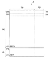
図2はメモリコア4の記憶領域5の構成の一例を示す図である。図2に示されるように、記憶領域5は、N個(N≧2)のセクタ50で構成されている。本例では、N=512であるが、Nは512以外の値であってもよい。データ処理システム1では、記憶領域5内のデータはセクタ50単位で消去される。したがって、各セクタ50は、データ消去単位である消去単位領域であると言える。
<Configuration of memory core storage area>
FIG. 2 is a diagram showing an example of the configuration of the
記憶領域5がN個のセクタ50に対しては、N個の物理アドレス(「物理ADD」と表されることがある)がそれぞれ割り当てられている。本例では、512個のセクタ50に対して、000h〜1FFh(hは16進数を示す)の物理アドレスがそれぞれ割り当てられている。
N physical addresses (sometimes referred to as “physical ADD”) are allocated to
ホスト装置2は、物理アドレス000h〜1EFhの496個のセクタ50で構成される第1部分記憶領域5Aに対してアクセスすることが可能である。一方で、ホスト装置2は、物理アドレス1F0h〜1FFhの16個のセクタ50で構成される第2部分記憶領域5Bに対してアクセスすることができない。第2部分記憶領域5Bには、制御プログラム300がファームウェアとして記憶される。
The
各セクタ50は、ユーザデータ領域50Aと、冗長領域50Bとを備えている。コントローラ30は、第1部分記憶領域5Aの各セクタ50のユーザデータ領域50Aに対して、ホスト装置2からの出力データ210を書き込むことが可能である。
Each
図3は各セクタ50の構成の一例を示す図である。図3に示されるように、各セクタ50はM個(M≧2)のページPGで構成されている。本例では、M=8であるが、Mは8以外の値であってもよい。データ処理システム1では、記憶領域5に対するデータ書き込み及びデータ読み出しは、ページPG単位で行うことが可能である。またデータ処理システム1では、ユーザデータ領域50A及び冗長領域50Bのそれぞれに対して、独立して、データ書き込み及びデータ読み出しを行うことができる。本例では、セクタ50を構成する8個のページPGに対して、0番から7番までの番号が割り当てられている。以後、m番(0≦m≦7)のページPGを「ページm」と呼ぶことがある。
FIG. 3 is a diagram illustrating an example of the configuration of each
本例では、メモリ装置3はフラッシュメモリであるため、コントローラ30は、セクタ50にデータを書き込む場合には、当該セクタ50のデータを消去した上で当該セクタ50にデータを書き込む必要がある。データ書き込みは「プログラム」と呼ばれることがある。
In this example, since the
本例では、第1部分記憶領域5Aを構成する496個のセクタ50のうち、256個のセクタ50が、R/Wアクセスセクタ50として使用される。一方で、当該496個のセクタ50のうち、240個のセクタ50のそれぞれが、消去済みセクタ50あるいは消去待ちセクタ50として使用される。
In this example, 256
ここで、R/Wアクセスセクタ50とは、ホスト装置2がコントローラ30を通じてデータ書き込み及びデータ読み出しを行うことが可能なセクタ50である。R/Wアクセスセクタ50は、ホスト装置2がコントローラ30を通じてデータ書き込み及びデータ読み出しを行うことが可能な消去単位領域であるホストアクセス領域と言える。
Here, the R /
消去済みセクタ50はデータ消去済みのセクタ50である。ホスト装置2は消去済みセクタ50にアクセスできない。消去済みセクタ50は、データ消去済みの消去単位領域である消去済み領域と言える。
The erased
消去待ちセクタ50はデータ消去待ちのセクタ50である。ホスト装置2は消去待ちセクタ50にアクセスできない。消去待ちセクタ50は、データ消去待ちの消去単位領域である消去待ち領域と言える。
The
後述のように、データ処理システム1が動作しているときには、第1部分記憶領域5Aのセクタ50は、R/Wアクセスセクタ50から消去待ちセクタ50に変化することがある。また、第1部分記憶領域5Aのセクタ50は、消去待ちセクタ50から消去済みセクタ50に変化することがある。そして、第1部分記憶領域5Aのセクタ50は、消去済みセクタ50からR/Wアクセスセクタ50に変化することがある。データ処理システム1が動作しているときには、第1部分記憶領域5Aのセクタ50は、R/Wアクセスセクタ50、消去待ちセクタ50及び消去済みセクタ50の順に繰り返し変化することがある。以後、単にセクタ50と言えば、第1部分記憶領域5Aのセクタ50を意味する。
As will be described later, when the
<メモリ装置の動作モードについて>
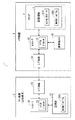
図4はコントローラ30の動作モードの一例を示す図である。コントローラ30の動作モードには、スタンバイモード、アイドルイレースモード(以後、「IEモード」と呼ぶ)及びリリースアイドルイレースモード(以後、「RIEモード」と呼ぶ)が含まれる。スタンバイモード、IEモード及びRIEモードは、メモリ装置3の動作モードとして見ることができる。なお、コントローラ30の動作モードには、他のモードが含まれてもよい。
<Operation mode of memory device>
FIG. 4 is a diagram illustrating an example of the operation mode of the
スタンバイモードのコントローラ30は、ホスト装置2からの書き込みコマンド、読み出しコマンド及び消去コマンドを受け付けることが可能である。書き込みコマンドは、セクタ50に対するデータ書き込みを指示するコマンドである。ホスト装置2は、書き込みコマンドを使用して、ページPG単位でメモリコア4に対してデータを書き込むことができる。書き込みコマンドはページプログラムコマンド(PPコマンド)と呼ばれることがある。読み出しコマンドは、セクタ50からのデータ読み出しを指示するコマンドである。ホスト装置2は、読み出しコマンドを使用して、ページPG単位でメモリコア4からデータを読み出すことができる。消去コマンドは、セクタ50のデータの消去を指示するコマンドであって、セクタイレースコマンド(SEコマンド)と呼ばれることがある。
The
コントローラ30は、書き込みコマンドを受け取ると、ホスト装置2が指定するセクタ50のページPGに、ホスト装置2が出力するデータを書き込む。またコントローラ30は、読み出しコマンドを受け取ると、ホスト装置2が指定するセクタ50のページPGからデータを読み出し、読み出したデータをI/F回路33を通じてホスト装置2に出力する。
When the
また、スタンバイモードのコントローラ30は、ホスト装置2が出力する、IEモードで動作することを指示する指示コマンドであるIEコマンドを受け付けることができる。コントローラ30は、IEコマンドを受け付けると、動作モードを、スタンバイモードからIEモードに変更する。
Further, the
IEモードのコントローラ30は、消去待ちセクタ50のデータを消去する。そして、IEモードのコントローラ30は、データを消去した消去待ちセクタ50を消去済みセクタ50に設定する。
The
また、IEモードのコントローラ30は、ホスト装置2が出力する、IEモードの解除を指示する解除コマンドであるRIEコマンドを受け付けることが可能である。コントローラ30は、RIEコマンドを受け付けると、動作モードを、IEモードからRIEモードに変更した後、スタンバイモードに変更する。
Also, the
RIEモードのコントローラ30は、IEモードにおいてデータが途中まで消去された消去待ちセクタ50が存在する場合には、当該消去待ちセクタ50の未消去のデータを消去する。そして、コントローラ30は、未消去のデータを消去した消去待ちセクタ50を消去済みセクタ50に設定する。その後、コントローラ30は、動作モードをスタンバイモードに変更する。また、コントローラ30は、データが途中まで消去された消去待ちセクタ50が存在しない場合には、特に処理を行わずに、動作モードをスタンバイモードに変更する。
The
本例では、スタンバイモードのコントローラ30は、ホスト装置2から消去コマンドを受け取ると、ホスト装置2から指定されたセクタ50のデータを消去する替りに、消去済みセクタ50をR/Wアクセスセクタ50に変更する。これにより、ホスト装置2から見れば、指定したセクタ50のデータが消去されたように見える。そして、コントローラ30は、データを消去しなかったセクタ50を消去待ちセクタ50とし、IEモードにおいて当該消去待ちセクタ50のデータを消去する。
In this example, when the
なお、スタンバイモード、IEモード及びRIEモードのコントローラ30の動作については後で詳細に説明する。
The operation of the
<メモリ装置が使用するテーブルについて>
コントローラ30は、2種類のテーブルを使用して、ホスト装置2からのコマンドに応じてメモリコア4にアクセスする。具体的には、コントローラ30は、R/Wアクセスセクタ50の物理アドレスと論理アドレス(「論理ADD」と表されることがある)との対応関係を示す論物変換テーブル(以後、「L2Pテーブル」と呼ぶ)60と、消去済みセクタ50及び消去待ちセクタ50の物理アドレスを管理するための管理テーブル70とを使用する。管理テーブル70には、消去済みセクタ50及び消去待ちセクタ50の物理アドレスが登録されている。コントローラ30は、メモリ装置3の起動時に、つまりメモリ装置3の電源がオフからオンになったときに、L2Pテーブル60及び管理テーブル70を生成して揮発性メモリ32に記憶する。
<About the table used by the memory device>
The
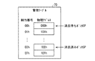
図5はL2Pテーブル60の一例を示す図である。図6は管理テーブル70の一例を示す図である。L2Pテーブル60では、256個のR/Wアクセスセクタ50の物理アドレスと、256個の論理アドレスとがそれぞれ対応付けられている。図5の例では、256個のR/Wアクセスセクタ50の物理アドレスと、00h〜FFhの256個の論理アドレスとがそれぞれ対応付けられている。L2Pテーブル60では、論理アドレスは変化しない。一方で、R/Wアクセスセクタ50に設定されるセクタ50が変化することから、L2Pテーブル60では、論理アドレスに対応付けられる物理アドレスは変化する。ホスト装置2では論理アドレスが管理されており、ホスト装置2は、論理アドレスを指定することによって、データ書き込み及びデータ読み出しを行うR/Wアクセスセクタ50を指定する。以後、R/Wアクセスセクタ50の物理アドレスを「R/Wアクセスアドレス」と呼ぶことがある。
FIG. 5 is a diagram illustrating an example of the L2P table 60. FIG. 6 is a diagram illustrating an example of the management table 70. In the L2P table 60, the physical addresses of 256 R /
管理テーブル70では、消去済みセクタ50及び消去待ちセクタ50についての240個の物理アドレスが登録されている。そして、管理テーブル70では、240個の物理アドレスに対して240個の番号が割当番号としてそれぞれ割り当てられている。図6の例では、00h〜EFhまでの240個の通し番号が割当番号として240個の物理アドレスにそれぞれ割り当てられている。管理テーブル70では、登録されている割当番号は変化しない。一方で、消去済みセクタ50に設定されるセクタ50が変化し、消去待ちセクタ50に設定されるセクタ50が変化することから、管理テーブル70では、割当番号に対応付けられる物理アドレスは変化する。コントローラ30は、消去済みセクタ50をR/Wアクセスセクタ50に変更すると、それに応じて管理テーブル70を更新する。
In the management table 70, 240 physical addresses for the erased
またコントローラ30は、管理テーブル70に登録されている複数の物理アドレスの一つを指し示す消去済みポインタSPと、当該複数の物理アドレスの一つを指し示す消去待ちポインタEPとを使用して、消去済みセクタ50及び消去待ちセクタ50の物理アドレスを管理する。
In addition, the
管理テーブル70の複数の物理アドレスには所定の順番が割り当てられている。具体的には、各物理アドレスには割当番号が所定の順番として割り当てられている。コントローラ30は、消去済みポインタSP及び消去待ちポインタEPのそれぞれを、割当番号(00h〜EFhまでの通し番号)の順に循環して移動する。
A predetermined order is assigned to the plurality of physical addresses in the management table 70. Specifically, an allocation number is allocated to each physical address in a predetermined order. The
管理テーブル70に登録されている240個の物理アドレスを割当番号の順で循環して見る場合において、消去済みポインタSPが指し示す物理アドレスから、消去待ちポインタEPが指し示す物理アドレスよりも一つ前の物理アドレスまでが、消去済みセクタ50の物理アドレスとなっている。また、管理テーブル70に登録されている240個の物理アドレスを割当番号の順で循環して見る場合において、消去待ちポインタEPが指し示す物理アドレスから、消去済みポインタSPが指し示す物理アドレスよりも一つ前の物理アドレスまでが、消去待ちセクタ50の物理アドレスとなっている。
When 240 physical addresses registered in the management table 70 are viewed in the order of the assigned numbers, the physical address indicated by the erased pointer SP is one prior to the physical address indicated by the erase wait pointer EP. The physical address of the erased
図6の例では、管理テーブル70に登録されている240の物理アドレスを割当番号の順で循環して見る場合において、消去待ちポインタEPが指し示す000hから、消去済みポインタSPが指し示す1EEhよりも一つ前の1EDhまでの238個の物理アドレスが、消去待ちセクタ50の物理アドレスとなっている。また、管理テーブル70に登録されている240の物理アドレスを割当番号の順で循環して見る場合において、消去済みポインタSPが指し示す1EEhから、消去待ちポインタEPが指し示す000hよりも一つ前の1EFhまでの2個の物理アドレスが、消去済みセクタ50の物理アドレスとなっている。
In the example of FIG. 6, when the 240 physical addresses registered in the management table 70 are viewed in the order of the assigned numbers, the number is 000h indicated by the erasure waiting pointer EP, and 1 EEh indicated by the erased pointer SP. The 238 physical addresses up to the previous 1EDh are the physical addresses of the
本例では、消去待ちポインタEP及び消去済みポインタSPは、ハードウェア回路によってコントローラ30に実装されているが、ソフトウェアで実現されてもよい。つまり、制御プログラム300を実行するマイクロプロセッサ31が消去待ちポインタEP及び消去済みポインタSPを生成してもよい。
In this example, the erasure waiting pointer EP and the erased pointer SP are mounted on the
以後、消去待ちセクタ50の物理アドレスを「消去待ちアドレス」と呼び、消去済みセクタ50の物理アドレスを「消去済みアドレス」と呼ぶことがある。
Hereinafter, the physical address of the erase-waiting
スタンバイモードのコントローラ30は、ホスト装置2から消去コマンドを受け取ると、L2Pテーブル60において、ホスト装置2から指定される論理アドレスに対応するR/Wアクセスアドレスを、消去済みポインタSPが指し示す、消去済みセクタ50の消去済みアドレスに置き換える。これにより、消去済みセクタ50からR/Wアクセスセクタ50に変更されるセクタ50の物理アドレスがL2Pテーブル60に登録される。また、スタンバイモードのコントローラ30は、管理テーブル70において、消去済みポインタSPが指し示す、消去済みセクタ50の消去済みアドレスを、ホスト装置2から指定される論理アドレスに対応するR/Wアクセスアドレスに置き換え、次の物理アドレスを指し示すように消去済みポインタSPを移動する。これにより、R/Wアクセスセクタ50から消去待ちセクタ50に変更されるセクタ50の物理アドレスが、管理テーブル70に登録される。
When the
図7には、L2Pテーブル60において、ホスト装置2から指定される論理アドレスに対応するR/Wアクセスアドレスが、消去済みポインタSPが指し示す消去済みアドレスに置き換えられる様子の一例が示される。また図7には、管理テーブル70において、消去済みポインタSPが指し示す消去済みアドレスが、ホスト装置2から指定される論理アドレスに対応するR/Wアクセスアドレスに置き換えられ、次の物理アドレスを指し示すように消去済みポインタSPが移動する様子の一例が示されている。図7の例では、L2Pテーブル60において、ホスト装置2から指定される論理アドレス00hに対応するR/Wアクセスアドレス100hが、消去済みポインタSPが指し示す消去済みアドレス1EEhに置き換えられている。また図7の例では、管理テーブル70において、消去済みポインタSPが指し示す消去済みアドレス1EEhが、ホスト装置2から指定される論理アドレスに対応するR/Wアクセスアドレス100hに置き換えられている。
FIG. 7 shows an example of how the R / W access address corresponding to the logical address designated by the
IEモードのコントローラ30は、管理テーブル70において、消去待ちポインタEPが指し示す物理アドレスの消去待ちセクタ50のデータを消去して当該消去待ちセクタ50を消去済みセクタ50に変更し、次の物理アドレスを指し示すように消去待ちポインタEPを移動する。これにより、データが消去されたセクタ50の物理アドレスが、消去済みアドレスとして管理テーブル70に登録される。
In the management table 70, the
図8には、次の物理アドレスを指し示すように消去待ちポインタEPが移動する様子の一例が示されている。図8では、消去済みアドレスにハッチングが示されている。図8の例では、消去待ちポインタEPが指し示す物理アドレス000hの消去待ちセクタ50のデータが消去され、消去待ちポインタEPが1つ次に移動している。図8の例では、データが消去されたセクタ50の物理アドレス000hが消去済みアドレスに変化している。
FIG. 8 shows an example of how the erasure waiting pointer EP moves to point to the next physical address. In FIG. 8, hatching is shown in the erased address. In the example of FIG. 8, the data in the erase-waiting
なお、消去済みポインタSP及び消去待ちポインタEPが同じ物理アドレスを指し示す場合には、管理テーブル70に登録されているすべての物理アドレスは、消去済みアドレスあるいは消去待ちアドレスとなる。消去済みポインタSPが次に移動して、消去済みポインタSP及び消去待ちポインタEPが指し示す物理アドレスが一致した場合には、管理テーブル70に登録されているすべての物理アドレスは、すべて消去待ちポインタEPとなる。一方で、消去待ちポインタEPが次に移動して、消去済みポインタSP及び消去待ちポインタEPが指し示す物理アドレスが一致した場合には、管理テーブル70に登録されているすべての物理アドレスは、すべて消去済みポインタSPとなる。 If the erased pointer SP and the erase wait pointer EP indicate the same physical address, all physical addresses registered in the management table 70 are erased addresses or erase wait addresses. When the erased pointer SP moves next and the physical addresses indicated by the erased pointer SP and the erase wait pointer EP match, all the physical addresses registered in the management table 70 are all erase wait pointers EP. It becomes. On the other hand, when the erase-waiting pointer EP moves next and the physical addresses indicated by the erased pointer SP and the erase-waiting pointer EP match, all the physical addresses registered in the management table 70 are erased. Is a completed pointer SP.
このように、コントローラ30は、消去済みポインタSP及び消去待ちポインタEPを使用することによって、消去済みアドレス及び消去待ちアドレスを1つの管理テーブル70で管理することから、消去済みアドレス及び消去待ちアドレスを管理するために必要なテーブルを記憶するために必要な記憶容量を低減することができる。
In this way, the
なお、コントローラ30は、消去済みアドレスが登録された消去済みテーブルと、消去待ちアドレスが登録された消去待ちテーブルとを使用してもよい。240個の物理アドレスのすべてが消去済みアドレスとなったり、240個の物理アドレスのすべてが消去待ちアドレスとなったりすることから、消去済みテーブル及び消去待ちテーブルのそれぞれは、240個分の物理アドレスを登録できる必要がある。つまり、消去済みテーブルと消去待ちテーブルとを合わせて、480個分の物理アドレスを記憶するための記憶容量が必要となる。これに対して、本例のように、240個の物理アドレスを登録できる1つの管理テーブル70を使用する場合には、240個分の物理アドレスを記憶するための記憶容量があればよい。
The
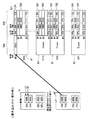
<冗長領域に書き込まれる管理情報について>
図9は第1部分記憶領域5Aのセクタ50に書き込まれる情報の一例を示す図である。上述のように、コントローラ30は、第1部分記憶領域5Aのセクタ50のユーザデータ領域50Aにホスト装置2からの出力データ210を書き込むことが可能である。一方で、コントローラ30は、第1部分記憶領域5Aのセクタ50の冗長領域50Bを、当該セクタ50の状態を管理するために使用する。以後、第1部分記憶領域5Aのセクタ50のユーザデータ領域50Aを特に「ホストデータ領域50A」と呼ぶことがある。また、第1部分記憶領域5Aのセクタ50の冗長領域50Bを特に「管理領域50B」と呼ぶことがある。
<Management information written to redundant area>
FIG. 9 is a diagram showing an example of information written in the
本例では、セクタ50の管理領域50Bのページ0が、ステータス情報が記憶される第1管理領域501として使用される。ステータス情報は、それを記憶するセクタ50が、R/Wアクセスセクタ50であるのか、消去済みセクタ50であるのか、消去待ちセクタ50であるのかを示す情報である。また、第1管理領域501には、L2Pテーブル60において、当該第1管理領域501を有するセクタ50の物理アドレスと対応付けられる論理アドレスが記憶される。
In this example,
本例では、冗長領域50Bの各ページPGの記憶容量は、例えば4バイトである。また、ユーザデータ領域50Aの各ページPGの記憶容量は、例えば512バイトである。第1管理領域501に記憶することが可能な32ビットのデータのうち、例えば、下位から25ビット目から32ビット目の1バイトのデータがステータス情報を示す。また、当該32ビットのデータのうち、例えば、下位から17ビット目から24ビット目の1バイトのデータが論理アドレスを示す。本例では、当該32ビットデータのうち、1ビット目から16ビット目までの2バイトのデータは使用されない。
In this example, the storage capacity of each page PG in the
ステータス情報は、それを記憶するセクタ50が消去済みセクタ50である場合には、例えばFFhを示す。またステータス情報は、それを記憶するセクタ50がR/Wアクセスセクタ50である場合には、例えばAAhを示す。そして、ステータス情報は、それを記憶するセクタ50が消去待ちセクタ50である場合には、例えば88hを示す。
The status information indicates, for example, FFh when the
図9に示される、物理アドレス000hのセクタ50及び物理アドレス0FFhのセクタ50はR/Wアクセスセクタ50である。また図9に示される物理アドレス100hのセクタ50は消去済みセクタ50である。そして、図9に示される物理アドレス1EFhのセクタ50は消去待ちセクタ50である。
The
以後、消去済みセクタ50内のステータス情報を「消去済みステータス情報」と呼ぶことがある。またR/Wアクセスセクタ50内のステータス情報を「R/Wアクセスステータス情報」と呼ぶことがある。そして消去待ちセクタ50内のステータス情報を「消去待ちステータス情報」と呼ぶことがある。
Hereinafter, the status information in the erased
なお、図9のホストデータ領域50Aに示される「Data」及び「Data_old」は、それぞれ、ホスト装置2が読み出すことができるホスト出力データ210及び消去待ちの出力データ210を意味している。また、図9のホストデータ領域50Aに示される「Erase」は、当該ホストデータ領域50A内にデータが記憶されていないことを意味する。以降の図に示される「Data」、「Data_old」及び「Erase」の意味も同様である。
Note that “Data” and “Data_old” shown in the
ここで、本例では、セクタ50のデータが消去されると、当該セクタ50の各ビットの値は“1”を示す。コントローラ30は、セクタ50のデータ消去済みのビットに“0”を書き込むことによって、当該ビットの値を“1”から“0”に書き換えることができる。コントローラ30は、セクタ50のデータを消去しない限り、セクタ50のビットの値を“1”から“0”に書き換えることができない。
Here, in this example, when the data of the
上述のように、本例では、消去済みステータス情報はFFhを示す。FFhは、2進数表記で1111_1111b(bは2進数を意味する)となることから、消去済みステータス情報を構成する各ビットの値はデータ消去済みのビットの値であると言える。セクタ50のデータが消去されて、当該セクタ50が消去済みセクタ50になると、当該消去済みセクタ50内のステータス情報は自動的にFFhを示す。
As described above, in this example, the erased status information indicates FFh. Since FFh is 1111_1111b (b means binary number) in binary notation, it can be said that the value of each bit constituting erased status information is the value of a data-erased bit. When the data in the
また、R/Wアクセスステータス情報はAAhを示す。AAhは、2進数表記で1010_1010b(bは2進数を意味する)となる。したがって、R/Wアクセスステータス情報は、消去済みステータス情報の上位から2ビット目、4ビット目、6ビット目、8ビット目の値を“0”に変更したものと一致する。コントローラ30は、消去済みステータス情報を記憶する第1管理領域501の一部のビットにデータ“0”を書き込むことによって、当該第1管理領域501内のステータス情報を消去済みステータス情報からR/Wアクセスステータス情報に変更することができる。具体的には、コントローラ30は、第1管理領域501における、消去済みステータス情報を記憶する8ビットの領域のうち、上位から2ビット目、4ビット目、6ビット目及び8ビット目のビットにデータ“0”を書き込むことによって、ステータス情報をR/Wアクセスステータス情報に変更することができる。
The R / W access status information indicates AAh. AAh is 1010_1010b (b means a binary number) in binary notation. Therefore, the R / W access status information matches that obtained by changing the values of the second bit, the fourth bit, the sixth bit, and the eighth bit from the top of the erased status information to “0”. The
また、消去待ちステータス情報は88hを示す。88hは、2進数表記で1000_1000b(bは2進数を意味する)となる。したがって、消去待ちステータス情報は、R/Wアクセスステータス情報の上位から3ビット目及び7ビット目の値を“0”に変更したものと一致する。コントローラ30は、R/Wアクセスステータス情報を記憶する第1管理領域501の一部のビットにデータ“0”を書き込むことによって、当該第1管理領域501内のステータス情報をR/Wアクセスステータス情報から消去待ちステータス情報に変更することができる。具体的には、コントローラ30は、第1管理領域501における、R/Wアクセスステータス情報を記憶する8ビットの領域のうち、上位から3ビット目及び7ビット目のビットにデータ“0”を書き込むことによって、ステータス情報を消去待ちステータス情報に変更することができる。
The erasure waiting status information indicates 88h. 88h is 1000_1000b in binary notation (b means binary number). Therefore, the erasure waiting status information matches that obtained by changing the values of the third bit and the seventh bit from the top of the R / W access status information to “0”. The
また本例では、セクタ50の管理領域50Bのページ1〜3が、ステータス情報の更新状況を示す第2管理領域502として使用される。第2管理領域502のページ1〜ページ3は、消去済みセクタ50、R/Wアクセスセクタ50及び消去待ちセクタ50にそれぞれ対応している。
In this example,
コントローラ30は、セクタ50を消去済みセクタ50に変更する場合には、当該セクタ50の第2管理領域502のページ1に第1所定情報を書き込む。言い換えれば、コントローラ30は、セクタ50の第1管理領域501内のステータス情報をFFhに書き換える場合には、当該セクタ50の第2管理領域502のページ1に第1所定情報を書き込む。第2管理領域502のページ1を第1更新管理領域と呼ぶと、コントローラ30は第1更新管理領域に第1所定情報を書き込む。第1所定情報は、例えば0000_0000hである。以後、ある領域に0000_0000hを書き込むことを「オール0を書き込む」と呼ぶことがある。本例では、第1更新管理領域にオール0が書き込まれる。
When changing the
コントローラ30は、セクタ50をR/Wアクセスセクタ50に変更する場合には、当該セクタ50の第2管理領域502のページ2に第2所定情報を書き込む。言い換えれば、コントローラ30は、セクタ50の第1管理領域501内のステータス情報をAAhに書き換える場合には、当該セクタ50の第2管理領域502のページ2に第2所定情報を書き込む。第2管理領域502のページ2を第2更新管理領域と呼ぶと、コントローラ30は第2更新管理領域に第2所定情報を書き込む。第2所定情報は、例えば0000_0000hである。
When changing the
コントローラ30は、セクタ50を消去待ちセクタ50に設定する場合には、当該セクタ50の第2管理領域502のページ3に第3所定情報を書き込む。言い換えれば、コントローラ30は、セクタ50の第1管理領域501内のステータス情報を88hに書き換える場合には、当該セクタ50の第2管理領域502のページ3に第3所定情報を書き込む。第2管理領域502のページ3を第3更新管理領域と呼ぶと、コントローラ30は第3更新管理領域に第3所定情報を書き込む。第3所定情報は、例えば0000_0000hである。
When setting the
以後、第1〜第3所定情報を第1〜第3ステータス更新情報とそれぞれ呼ぶことがある。また、第1〜第3ステータス更新情報を互いに区別する必要がないときには、それぞれを単にステータス更新情報と呼ぶことがある。 Hereinafter, the first to third predetermined information may be referred to as first to third status update information, respectively. Further, when there is no need to distinguish the first to third status update information from each other, each may be simply referred to as status update information.
上述の説明から理解できるように、セクタ50は、消去済みセクタ50からR/Wアクセスセクタ50に変化し、R/Wアクセスセクタ50から消去待ちセクタ50に変化する。したがって、消去済みセクタ50(図9の物理アドレス100hのセクタ50)の第2管理領域502では、ページ1だけにデータが書き込まれ、R/Wアクセスセクタ50(図9の物理アドレス000h及び0FFhのセクタ50)の第2管理領域502では、ページ1及びページ2だけにデータが書き込まれ、消去待ちセクタ50(図9の物理アドレス1EFhのセクタ50)の第2管理領域502では、ページ1、ページ2及びページ3のすべてにデータが書き込まれる。
As can be understood from the above description, the
<セクタの初期出荷状態>
図10は、製造されたメモリ装置3が出荷される際のセクタ50の状態の一例を示す図である。図10に示されるように、初期出荷状態のメモリ装置3では、物理アドレス000h〜0FFhまでのセクタ50がR/Wアクセスセクタ50に設定されている。そして、物理アドレス000h〜0FFhまでのセクタ50の第1管理領域501には、それぞれ論理アドレス00h〜FFhが記憶される。したがって、初期出荷状態のメモリ装置3の起動時には、図10に示されるように、000h〜0FFhの物理アドレスと、00h〜FFhの論理アドレスとがそれぞれ対応付けられたL2Pテーブル60が生成される。
<Initial shipment status of sector>
FIG. 10 is a diagram illustrating an example of the state of the
また、初期出荷状態のメモリ装置3では、物理アドレス100h〜1EFhまでのセクタ50が消去済みセクタ50に設定されている。初期出荷状態のメモリ装置3の記憶領域5には消去待ちセクタ50が含まれない。初期出荷状態のメモリ装置3の起動時には、図10に示されるように、例えば、割当番号00h〜EFhに対して、それぞれ、100h〜1EFhの物理アドレスが対応付けられた管理テーブル70が生成される。
In the
初期出荷状態のメモリ装置3の起動時に、コントローラ30は、各セクタ50の第1管理領域501内のステータス情報及び論理アドレスに基づいて、L2Pテーブル60及び管理テーブル70を生成して揮発性メモリ32に記憶する。
When the
なお、図10及び後述の図に記載される「消去済みセクタ=Full」及び「消去待ちセクタ=Empty」は、管理テーブル70内のすべての物理アドレスが消去済みアドレスであることと、管理テーブル70には消去待ちアドレスが登録されていないことをそれぞれ意味する。また、後述の図に記載される「消去済みセクタ=Empty」及び「消去待ちセクタ=Full」は、管理テーブル70には消去済みアドレスが登録されていないことと、管理テーブル70内のすべての物理アドレスが消去待ちアドレスであることをそれぞれ意味する。 Note that “erased sector = Full” and “erase-waiting sector = Empty” described in FIG. 10 and the later-described diagrams indicate that all physical addresses in the management table 70 are erased addresses, and that the management table 70 Means that no erasure waiting address is registered. In addition, “erased sector = Empty” and “sector to be erased = Full” described in the following figure indicate that the erased address is not registered in the management table 70 and that all physical addresses in the management table 70 are registered. This means that the address is an erasing wait address.
<各動作モードの詳細>
次に、スタンバイモード、IEモード及びRIEモードについて詳細に説明する。
<Details of each operation mode>
Next, the standby mode, IE mode, and RIE mode will be described in detail.
<スタンバイモードの詳細>
<書き込みコマンドを受け取った際のコントローラの動作>
ホスト装置2は、書き込みコマンドとともに論理アドレスを出力する。またホスト装置2は、メモリ装置3に対して書き込み先のページPGを指定するとともに、当該ページPGに書き込むデータを出力する。書き込みコマンドの種類としては、ホストデータ領域50Aにデータを書き込むことを指示する第1書き込みコマンドと、管理領域50Bにデータを書き込むことを指示する第2書き込みコマンドとがある。
<Details of standby mode>
<Operation of the controller when a write command is received>
The
メモリ装置3では、コントローラ30は、書き込みコマンドを受け取ると、L2Pテーブル60において、当該書き込みコマンドとともにホスト装置2が出力する論理アドレスに対応付けられている物理アドレス(R/Wアクセスアドレス)を特定する。そして、コントローラ30は、特定した物理アドレスのセクタ50(R/Wアクセスセクタ50)のホストデータ領域50A及び管理領域50Bのうち、書き込みコマンドの種類に応じた領域における、ホスト装置2が指定するページPGに対して、ホスト装置2が出力するデータを書き込む。このとき、コントローラ30は、メモリコア4に対して書き込みコマンドを出力し、当該書込みコマンドを受け取ったメモリコア4はセクタ50にデータを書きこむ。コントローラ30は、セクタ50にデータを書き込む際には管理テーブル70を使用しない。その後、コントローラ30は、ホスト装置2からの書き込みコマンドに応じた処理が完了したことを、I/F回路33を通じてホスト装置2に通知する。
In the
図11は、ホスト装置2からのデータがセクタ50のホストデータ領域50Aに対して書き込まれる様子の一例を示す図である。図11には、ホスト装置2が第1書き込みコマンド及び論理アドレス00hを出力し、かつ書き込み先のページPGとしてページ0を指定する場合の例が示されている。図11の例では、L2Pテーブル60では、論理アドレス00hに物理アドレス000hが対応付けられていることから、物理アドレス000hが割り当てられたR/Wアクセスセクタ50のホストデータ領域50Aのページ0に対して、ホスト装置2が出力するデータが書き込まれる。
FIG. 11 is a diagram illustrating an example of a state in which data from the
<読み出しコマンドを受け取った際のコントローラの動作>
ホスト装置2は、読み出しコマンドとともに論理アドレスを出力する。またホスト装置2は、メモリ装置3に対して読み出し対象のページPGを指定する。読み出しコマンドの種類としては、ホストデータ領域50Aからデータを読み出すことを指示する第1読み出しコマンドと、管理領域50Bからデータを読み出すことを指示する第2読み出しコマンドとがある。
<Operation of the controller when a read command is received>
The
メモリ装置3では、コントローラ30は、読み出しコマンドを受け取ると、L2Pテーブル60において、当該読み出しコマンドとともにホスト装置2が出力する論理アドレスに対応付けられている物理アドレス(R/Wアクセスアドレス)を特定する。そして、コントローラ30は、特定した物理アドレスのセクタ50(R/Wアクセスセクタ50)のホストデータ領域50A及び管理領域50Bのうち、読み出しコマンドの種類に応じた領域における、ホスト装置2が指定するページPGからデータを読み出す。このとき、コントローラ30は、メモリコア4に対して読み出しコマンドを出力し、当該読み出しコマンドを受け取ったメモリコア4はセクタ50からデータを読み出してコントローラ30に出力する。コントローラ30は、読み出したデータをI/F回路33を通じてホスト装置2に出力する。コントローラ30は、セクタ50からデータを読み出す際には管理テーブル70を使用しない。
In the
<消去コマンドを受け取った際のコントローラの動作>
図12は、メモリコア4に消去待ちセクタ50が含まれる場合において、消去コマンドを受け取るコントローラ30の動作の一例を示すフローチャートである。ホスト装置2は、読み出しコマンドとともに論理アドレスを出力する。以後、ホスト装置2が出力する論理アドレスを「指定論理アドレス」と呼ぶことがある。
<Operation of the controller when an erase command is received>
FIG. 12 is a flowchart showing an example of the operation of the
図12に示されるように、ステップs1において、コントローラ30は、ホスト装置2からの消去コマンド及び指定論理アドレスを受け取ると、ステップs2において、消去済みポインタSPが指し示す消去済みアドレスを特定する。この特定された消去済みアドレスを「特定消去済みアドレス」と呼ぶ。そしてステップs3において、コントローラ30は、消去済みポインタSPを次に移動する。
As shown in FIG. 12, when the
次にステップs4において、コントローラ30は、特定消去済みアドレスが割り当てられた消去済みセクタ50をR/Wアクセスセクタ50に変更する。具体的には、コントローラ30は、特定消去済みアドレスのセクタ50の第1管理領域501内のステータス情報をFFhからAAhに変更し、当該第1管理領域501内の論理アドレスを指定論理アドレスに変更する。コントローラ30は、消去済みセクタ50の第1管理領域501における、消去済みステータス情報(FFh)を記憶する8ビットの領域のうち、上位から2ビット目、4ビット目、6ビット目及び8ビット目のビットにデータ“0”を書き込むことによって、ステータス情報を、消去済みステータス情報(FFh)からR/Wアクセスステータス情報(AAh)に変更する。コントローラ30は、消去済みセクタ50のデータを消去することなく、ステータス情報を、消去済みステータス情報(FFh)からR/Wアクセスステータス情報(AAh)に変更することができることから、簡単にステータス情報を変更することができる。
Next, in step s4, the
ここで、コントローラ30は、セクタ50のページPGにデータを書き込むと、当該ページPGからデータを読み出し、読み出したデータと、書き込んだデータとが一致するか否かを判定して、正しくデータが書き込まれていることを確認するベリファイ処理を行う。ステップs4において、コントローラ30は、特定消去済みアドレスのセクタ50の第1管理領域501(ページ0)にデータを書き込んでステータス情報及び論理アドレスを変更すると、ベリファイ処理を行う。以後、特に説明しなくても、コントローラ30はセクタ50にデータを書き込んだ後にベリファイ処理を行うものとする。
Here, when data is written to the page PG of the
次にステップs5において、コントローラ30は、特定消去済みアドレスのセクタ50の第2管理領域502のページ2にオール0を書き込む。
Next, in step s5, the
次にステップs6において、コントローラ30は、L2Pテーブル60において、指定論理アドレスに対応するR/Wアクセスアドレスを特定する。この特定されたR/Wアクセスアドレスを「特定R/Wアクセスアドレス」と呼ぶ。
Next, in step s6, the
次にステップs7において、コントローラ30は、特定R/Wアクセスアドレスが割り当てられたR/Wアクセスセクタ50を消去待ちセクタ50に変更する。具体的には、コントローラ30は、特定R/Wアクセスアドレスのセクタ50の第1管理領域501内のステータス情報をAAhから88hに変更する。コントローラ30は、R/Wアクセスセクタ50の第1管理領域501における、R/Wアクセスステータス情報(AAh)を記憶する8ビットの領域のうち、上位から3ビット目及び7ビット目のビットにデータ“0”を書き込むことによって、ステータス情報を、R/Wアクセスステータス情報(AAh)から消去待ちステータス情報(88h)に変更する。コントローラ30は、R/Wアクセスセクタ50のデータを消去することなく、ステータス情報を、R/Wアクセスステータス情報(AAh)から消去待ちステータス情報(88h)に変更することができることから、簡単にステータス情報を変更することができる。
Next, in step s7, the
次にステップs8において、コントローラ30は、特定R/Wアクセスアドレスが割り当てられたセクタ50の第2管理領域502のページ3にオール0を書き込む。
Next, in step s8, the
次にステップs9において、コントローラ30は、L2Pテーブル60において、特定R/Wアクセスアドレスを特定消去済みアドレスに置き換える。そしてステップs10にて、コントローラ30は、管理テーブル70において、特定消去済みアドレスを特定R/Wアクセスアドレスに置き換える。ステップs10の実行後、コントローラ30は、ホスト装置2からの消去コマンドに応じた処理が完了したことを、I/F回路33を通じてホスト装置2に通知する。
Next, in step s9, the
以上のようにしてメモリ装置3が動作することによって、ホスト装置2が消去コマンド及び指定論理アドレスを出力する場合には、メモリ装置3では、指定論理アドレスに対応するセクタ50のデータが疑似的に消去される。
When the
図13〜19は、セクタ50、L2Pテーブル60及び管理テーブル70の状態が図11に示される状態の場合に、消去コマンド及び指定論理アドレス00hを受け取ったコントローラ30の一連の動作の一例を説明するための図である。
13 to 19 illustrate an example of a series of operations of the
コントローラ30は、消去コマンド及び指定論理アドレス00hを受け取ると(ステップs1)、消去済みポインタSPが指し示す消去済みアドレス100hを特定する(図13参照)。そして、図13に示されるように、コントローラ30は、消去済みポインタSPを次に移動する。これにより、管理テーブル70上では、消去済みセクタ50の数が239個となり、消去待ちセクタ50の数が1個となる。図13での「消去済みセクタ=239」は、消去済みセクタ50の数が239個であることを意味し、「消去待ちセクタ=1」は、消去待ちセクタ50の数が1個であることを意味している。
Upon receiving the erase command and the designated
次に図14に示されるように、コントローラ30は、特定消去済みアドレス100hのセクタ50の第1管理領域501内のステータス情報をFFhからAAhに変更する(ステップs4)。また図15に示されるように、コントローラ30は、特定消去済みアドレス100hのセクタ50の第1管理領域501内の論理アドレスFFhを、ホスト装置2からの指定論理アドレス00hに変更する(ステップs4)。これにより、特定消去済みアドレス100hが割り当てられた消去済みセクタ50がR/Wアクセスセクタ50に変更される。
Next, as shown in FIG. 14, the
次に図16に示されるように、コントローラ30は、特定消去済みアドレス100hのセクタ50の第2管理領域502のページ2にオール0を書き込む(ステップs5)。
Next, as shown in FIG. 16, the
次にコントローラ30は、L2Pテーブル60において、指定論理アドレスに対応するR/Wアクセスアドレス000hを特定する(ステップs6)。そして、図17に示されるように、コントローラ30は、特定R/Wアクセスアドレス000hが割り当てられたR/Wアクセスセクタ50の第1管理領域501内のステータス情報をAAhから88hに変更する(ステップs7)。これにより、特定R/Wアクセスアドレス000hが割り当てられたR/Wアクセスセクタ50が消去待ちセクタ50に変更される。
Next, the
次に図18に示されるように、コントローラ30は、特定R/Wアクセスアドレス000hが割り当てられたセクタ50の第2管理領域502のページ3にオール0を書き込む。
Next, as shown in FIG. 18, the
次に図19に示されるように、コントローラ30は、L2Pテーブル60において、特定R/Wアクセスアドレス000hを特定消去済みアドレス100hに置き換える(ステップs9)。そして、コントローラ30は、管理テーブル70において、特定消去済みアドレス100hを特定R/Wアクセスアドレス000hに置き換える(ステップs10)。その後、コントローラ30は、ホスト装置2からの消去コマンドに応じた処理が完了したことを、I/F回路33を通じてホスト装置2に通知する。
Next, as shown in FIG. 19, the
以上のように、本例では、コントローラ30は、消去コマンド及び指定論理アドレスを受け取った場合、指定論理アドレスに対応するセクタ50のデータを消去せずに、当該セクタ50の代りに、消去済みセクタ50を当該指定論理アドレスに対応付けることによって、指定論理アドレスに対応するセクタ50のデータを疑似的に消去している。セクタ50のデータを消去するために必要な時間は非常に大きいことから、このようにセクタ50のデータが疑似的に消去されることにより、コントローラ30の処理時間を大幅に低減することができる。よって、メモリ装置3の性能が向上する。またホスト装置2は、セクタ50のデータが実際に消去される場合と比較して、消去コマンドの出力から書き込みコマンドの出力までの時間を短くすることができる。よって、ホスト装置2は、セクタ50のデータが実際に消去される場合と比較して、セーブデータ等のデータを短時間でメモリ装置3に保存することができる。
As described above, in this example, when the
次に、メモリコア4に消去済みセクタ50が含まれない場合において、消去コマンドを受け取るコントローラ30の動作について説明する。図20は当該動作の一例を示すフローチャートである。メモリコア4に消去済みセクタ50が含まれない場合において、コントローラ30は、消去コマンドを受け取ると、消去待ちセクタ50のデータを消去して消去済みセクタ50を生成した後に、上記のステップs2〜10を実行する。
Next, the operation of the
図20に示されるように、ステップs21において、コントローラ30は、ホスト装置2からの消去コマンド及び指定論理アドレスを受け取ると、ステップs22において、消去待ちポインタEPが指し示す消去待ちアドレスを特定する。この特定された消去待ちアドレスを「特定消去待ちアドレス」と呼ぶ。そしてステップs23において、コントローラ30は、消去待ちポインタEPを次に移動する。
As shown in FIG. 20, when the
次にステップs24において、コントローラ30は、特定消去待ちアドレスが割り当てられた消去待ちセクタ50の管理領域50Bのページ0,4,5,6,7に対してオール0を書き込む。
Next, in step s24, the
次にステップs25において、コントローラ30は、特定消去待ちアドレスが割り当てられた消去待ちセクタ50のデータを消去するために、メモリコア4に対して消去コマンドを出力する。消去コマンドを受け取ったメモリコア4は、特定消去待ちアドレスが割り当てられた消去待ちセクタ50のデータを消去する。これにより、特定消去待ちアドレスが割り当てられた消去待ちセクタ50が消去済みセクタ50に変更される。その後、メモリコア4は、データ消去が完了したことを通知する消去完了通知をコントローラ30に出力する。
Next, in step s25, the
ステップs26において、コントローラ30は、消去完了通知を受け取ると、ステップs27において、特定消去待ちアドレスが割り当てられた消去待ちセクタ50の第2管理領域502のページ1にオール0を書き込む。その後、コントローラ30は上記のステップs2〜s10を実行する。ステップs10の実行後、コントローラ30は、ホスト装置2からの消去コマンドに応じた処理が完了したことを、I/F回路33を通じてホスト装置2に通知する。
In step s26, when the
図21は、メモリコア4に消去済みセクタ50が含まれない場合のセクタ50、L2Pテーブル60及び管理テーブル70の状態の一例を示す図である。図21に示される、物理アドレス000h及び0FFhのセクタ50はR/Wアクセスセクタ50である。また図21に示される、物理アドレス100h及び1EFhのセクタ50は消去待ちセクタ50である。
FIG. 21 is a diagram illustrating an example of states of the
図22〜29は、セクタ50、L2Pテーブル60及び管理テーブル70の状態が図21に示される状態の場合に、消去コマンド及び指定論理アドレス00hを受け取ったコントローラ30の一連の動作の一例を説明するための図である。
22 to 29 illustrate an example of a series of operations of the
コントローラ30は、消去コマンド及び指定論理アドレス00hを受け取ると(ステップs21)、消去待ちポインタEPが指し示す消去待ちアドレス100hを特定する(ステップs22)。そして図22に示されるように、コントローラ30は、消去待ちポインタEPを次に移動する(ステップs23)。
When the
次に、図22に示されるように、コントローラ30は、特定消去待ちアドレス100hが割り当てられた消去待ちセクタ50の管理領域50Bのページ0,4,5,6,7に対してオール0を書き込む(ステップs24)。
Next, as shown in FIG. 22, the
次にコントローラ30は、メモリコア4に対して消去コマンドを出力する(ステップs25)。これにより、図23に示されるように、特定消去待ちアドレス100hが割り当てられた消去待ちセクタ50のデータが消去される。
Next, the
その後、コントローラ30は、メモリコア4から消去完了通知を受け取ると(ステップs26)、図24に示されるように、特定消去待ちアドレス100hが割り当てられた消去待ちセクタ50の第2管理領域502のページ1にオール0を書き込む(ステップs27)。
Thereafter, when the
次にコントローラ30は、消去済みポインタSPが指し示す消去済みアドレス100hを特定する(ステップs2)。そして、図25に示されるように、コントローラ30は、消去済みポインタSPを次に移動する(ステップs3)。
Next, the
次に図25に示されるように、コントローラ30は、特定消去済みアドレス100hのセクタ50の第1管理領域501内のステータス情報をFFhからAAhに変更する(ステップs4)。また図26に示されるように、コントローラ30は、特定消去済みアドレス100hのセクタ50の第1管理領域501内の論理アドレスFFhを、ホスト装置2からの指定論理アドレス00hに変更する(ステップs4)。
Next, as shown in FIG. 25, the
次に図27に示されるように、コントローラ30は、特定消去済みアドレス100hのセクタ50の第2管理領域502のページ2にオール0を書き込む(ステップs5)。
Next, as shown in FIG. 27, the
次にコントローラ30は、L2Pテーブル60において、指定論理アドレスに対応するR/Wアクセスアドレス000hを特定する(ステップs6)。そして、図28に示されるように、コントローラ30は、特定R/Wアクセスアドレス000hが割り当てられたR/Wアクセスセクタ50の第1管理領域501内のステータス情報をAAhから88hに変更する(ステップs7)。
Next, the
次に図29に示されるように、コントローラ30は、特定R/Wアクセスアドレス000hが割り当てられたセクタ50の第2管理領域502のページ3にオール0を書き込む。
Next, as shown in FIG. 29, the
次に図30に示されるように、コントローラ30は、L2Pテーブル60において、特定R/Wアクセスアドレス000hを特定消去済みアドレス100hに置き換える(ステップs9)。そして、コントローラ30は、管理テーブル70において、特定消去済みアドレス100hを特定R/Wアクセスアドレス000hに置き換える(ステップs10)。その後、コントローラ30は、ホスト装置2からの消去コマンドに応じた処理が完了したことを、I/F回路33を通じてホスト装置2に通知する。
Next, as shown in FIG. 30, the
なお、コントローラ30が消去コマンドを受け取ったときに行う複数の処理の順番は上記の例に限られない。例えば、ステップs3はステップs1よりも後であればいつでも実行されてよい。また、ステップs6〜s8はステップs2〜s5の前に実行されてもよい。また、ステップs10はステップs9の前に実行されてもよい。また、ステップs9,s10は、ステップs2,s6の後であればいつでも実行されてよい。また、ステップs5はステップs4の前に実行されてもよい。また、ステップs8はステップs7の前に実行されてもよい。
Note that the order of the plurality of processes performed when the
<IEモードの詳細>
図31は、ホスト装置2からのIEコマンドを受け取ったコントローラ30の動作の一例を示すフローチャートである。図31に示されるように、スタンバイモードのコントローラ30は、ステップs31において、ホスト装置2からのIEコマンドを受け取ると、ステップs32において、動作モードをスタンバイモードからIEモードに変更する。
<Details of IE mode>
FIG. 31 is a flowchart illustrating an example of the operation of the
次にステップs33において、IEモードのコントローラ30は、IEコマンドを受け取ってから所定時間が経過する前にIREコマンドを受け取ったか否かを判定する。所定時間は例えば数百msに設定される。コントローラ30は、IEコマンドを受け取ってから所定時間が経過する前にIREコマンドを受け取った場合には(ステップs33でYES)、ステップs34において、消去待ちセクタ50のデータを消去せずに、動作モードをIEモードからRIEモードに変更する。したがって、ホスト装置2が、IEコマンドを出力してから所定時間が経過する前にIREコマンドを出力する場合には、メモリ装置3ではセクタ50のデータの消去が行われない。一方で、コントローラ30は、IEコマンドを受け取ってから、IREコマンドを受け取らずに所定時間が経過すると(ステップs33でNO)、消去待ちセクタ50のデータの消去を開始する。
Next, in step s33, the
コントローラ30は、消去待ちセクタ50のデータを消去する際には、まずステップs35において、消去待ちポインタEPが指し示す消去待ちアドレスを特定する。次にステップs36において、消去待ちポインタEPを次に移動する。
When erasing the data in the
次にステップs37において、コントローラ30は、ステップs35で特定した特定消去待ちアドレスが割り当てられた消去待ちセクタ50の管理領域50Bのページ0,4,5,6,7に対してオール0を書き込む。
Next, in step s37, the
次にステップs38において、コントローラ30は、特定消去待ちアドレスが割り当てられた消去待ちセクタ50のデータを消去するために、メモリコア4に対して消去コマンドを出力する。消去コマンドを受け取ったメモリコア4は、特定消去待ちアドレスが割り当てられた消去待ちセクタ50のデータを消去する。これにより、特定消去待ちアドレスが割り当てられた消去待ちセクタ50が消去済みセクタ50に変更される。その後、メモリコア4は消去完了通知をコントローラ30に出力する。
Next, in step s38, the
ステップs39において、コントローラ30は消去完了通知を受け取ると、ステップs40において、特定消去待ちアドレスが割り当てられたセクタ50の第2管理領域502のページ1にオール0を書き込む。
In step s39, when the
次にステップs41において、コントローラ30は、メモリコア4において消去待ちセクタ50が無くなったか否かを判定する。コントローラ30は、メモリコア4において消去待ちセクタ50が無くなった場合には(ステップs41でのYES)、ステップs42において、動作モードをIEモードに維持する。一方で、コントローラ30は、メモリコア4において消去待ちセクタ50が存在する場合には(ステップs41でのNO)、再度ステップs35を実行して、消去待ちポインタEPが指し示す消去待ちアドレスを特定する。以後、コントローラ30は同様に動作する。
Next, in step s41, the
なお、コントローラ30は、ステップs33において、IEコマンドを受け取ってから、IREコマンドを受け取らずに所定時間が経過したと判定した場合であって、メモリコア4に消去待ちセクタ50が存在しない場合には、ステップs35〜ステップs41を実行せずにステップs42を実行する。
If the
IEモードのコントローラ30は、ステップs35〜s42の間でホスト装置2からRIEコマンドを受け取ると、すぐに動作モードをIEモードからRIEモードに変更する。したがって、消去待ちセクタ50のデータが消去されている最中に、動作モードがIEモードからRIEモードに変化することがある。コントローラ30は、IEモードで動作する場合、IREコマンドを受け取ると、消去待ちセクタ50のデータを消去している最中であるか否かにかかわらず動作モードをIEモードからRIEモードに変更する。また、IEモードのコントローラ30は、メモリコア4の記憶領域5に複数の消去待ちセクタ50が含まれる場合には、RIEコマンドを受け取るまで、当該複数の消去待ちセクタ50のデータ消去を継続して行う。
When the
図32は、セクタ50、L2Pテーブル60及び管理テーブル70の状態の一例を示す図である。図33〜35は、セクタ50、L2Pテーブル60及び管理テーブル70の状態が図32に示される状態の場合に、IEコマンドを受け取ったコントローラ30が消去待ちセクタ50のデータを消去する際の一連の動作の一例を説明するための図である。図32に示される、物理アドレス000h及び0FFhのセクタ50はR/Wアクセスセクタ50である。図32に示される、物理アドレス100hのセクタ50は消去待ちセクタ50である。図32に示される、物理アドレス1EFhのセクタ50は消去済みセクタ50である。
FIG. 32 is a diagram illustrating an example of states of the
コントローラ30は、上述のステップs31〜s33を実行し、ステップs33において、IEコマンドを受け取ってから、IREコマンドを受け取らずに所定時間が経過したと判定すると、消去待ちポインタEPが指し示す消去待ちアドレス100hを特定する(ステップs35)。次に図33に示されるように、コントローラ30は、消去待ちポインタEPを次に移動する(ステップs36)。
If the
次に図33に示されるように、コントローラ30は、特定消去待ちアドレス100hが割り当てられた消去待ちセクタ50の管理領域50Bのページ0,4,5,6,7に対してオール0を書き込む(ステップs37)。
Next, as shown in FIG. 33, the
次にコントローラ30は、メモリコア4に対して消去コマンドを出力する(ステップs38)。これにより、図34に示されるように、特定消去待ちアドレス100hが割り当てられた消去待ちセクタ50のデータが消去され、当該消去待ちセクタ50が消去済みセクタ50に変化する。
Next, the
その後、コントローラ30は、消去完了通知を受け取ると(ステップs39)、図35に示されるように、特定消去待ちアドレス100hがセクタ50の第2管理領域502のページ1にオール0を書き込む(ステップs40)。
Thereafter, when the
次にコントローラ30は、メモリコア4において消去待ちセクタ50が無くなったか否かを判定する(ステップs41)。ここでは、メモリコア4に消去待ちセクタ50が存在することから、コントローラ30は、消去待ちポインタEPが現在指し示す消去待ちアドレス101hを特定する(ステップs35)。以後、コントローラ30は同様に動作する。
Next, the
以上のように、IEモードのコントローラ30は、メモリコア4の記憶領域5に複数の消去待ちセクタ50が含まれる場合には、RIEコマンドを受け取るまで、当該複数の消去待ちセクタ50のデータ消去を継続して行う。したがって、ホスト装置2は、消去待ちセクタ50のデータが消去されるたびにコマンドを出力する必要がなくなる。よって、コントローラ30は、消去待ちセクタ50のデータを消去するたびにホスト装置2からのコマンドを処理する必要はなく、メモリ装置3が複数の消去待ちセクタ50のデータを消去する処理を簡素化することができる。よって、メモリ装置3の性能が向上する。また、ホスト装置2の処理も簡素化される。
As described above, when the
なお、コントローラ30は、IEモードで動作している場合に、消去待ちセクタ50が無くなった場合には(ステップs41でのYES)、RIEモードを経由せずに、動作モードをIEモードから直接スタンバイモードに変更してもよい。
In addition, when operating in the IE mode and the erasing-waiting
<IEモードでのメモリ装置の消費電流>
図36は、IEモードのコントローラ30が、消去待ちセクタ50のデータを消去する際のメモリ装置3の消費電流波形の一例を示す図である。以後、単に消費電流と言えば、メモリ装置3の消費電流を意味する。
<Current consumption of memory device in IE mode>
FIG. 36 is a diagram illustrating an example of a current consumption waveform of the
図36に示されるように、IEモードのコントローラ30が、消去待ちセクタ50のデータを消去する際には、動作期間600,610,620,630が順に現れる。動作期間600は、特定消去待ちアドレスが割り当てられたセクタ50の管理領域50Bのページ0,4,5,6,7に対しオール0が書き込まれて、その後、当該ページ0,4,5,6,7に対するベリファイ処理が行われる期間(ステップs37)である。動作期間610は、消去コマンドを受け取ったメモリコア4が、特定消去待ちアドレスが割り当てられたセクタ50のデータを消去する期間(ステップs38,s39)である。動作期間620は、データ消去されたセクタ50のホストデータ領域50A及び管理領域50Bに対してベリファイ処理が行われる期間である。動作期間630は、データ消去されたセクタ50の第2管理領域502のページ1にオール0が書き込まれて、その後、当該ページ1に対するベリファイ処理が行われる期間(ステップs40)である。
As shown in FIG. 36, when the
本例では、図36に示されるように、動作期間610での消費電流は、動作期間600での当該消費電流よりも大きくなっている。また、動作期間620での消費電流は、動作期間610での消費電流よりも小さくなっている。そして、動作期間630での消費電流は、動作期間620での消費電流よりも大きくなり、動作期間610よりも小さくなっている。これらのことから、セクタ50のデータが消去されているときの消費電流は、セクタ50に対してデータ書き込みを行うときの消費電流よりも大きく、セクタ50に対してデータ読み出しを行うときの消費電流よりも大きくなると言える。
In this example, as shown in FIG. 36, the current consumption during the
なお、スタンバイモードのコントローラ30は、消去コマンドを受け取った場合、メモリコア4に消去済みセクタ50が含まれないときには、上述のように、消去待ちセクタ50のデータを消去して消去済みセクタ50を生成した後に、ステップs2〜10を実行する。スタンバイモードのコントローラ30が消去待ちセクタ50のデータを消去する際の当該コントローラ30の動作は、IEモードのコントローラ30が消去待ちセクタ50のデータを消去する際の当該コントローラ30の動作と同様であることから、スタンバイモードのコントローラ30が消去待ちセクタ50のデータを消去する場合にも、図36に示される動作期間600,610,620,630が順に現れる。
When the
<RIEモードの詳細>
図37は、ホスト装置2からのRIEコマンドを受け取ったコントローラ30の動作の一例を示すフローチャートである。図37に示されるように、IEモードのコントローラ30は、ステップs51において、ホスト装置2からのRIEコマンドを受け取ると、ステップs52において、動作モードをIEモードからRIEモードに変更する。
<Details of RIE mode>
FIG. 37 is a flowchart showing an example of the operation of the
次にステップs53において、RIEモードのコントローラ30は、データが途中まで消去された消去待ちセクタ50がメモリコア4に存在するか否かを判定する。コントローラ30は、データが途中まで消去された消去待ちセクタ50がメモリコア4に存在する場合には、ステップs54において、当該消去待ちセクタ50の未消去のデータを消去して、当該消去待ちセクタ50を消去済みセクタ50に変更する。そしてステップs55において、コントローラ30は、動作モードをRIEモードからスタンバイモードに変更する。コントローラ30が、IEモードで動作する場合に、消去待ちセクタ50のデータを消去している最中にRIEコマンドを受け取ると、データが途中まで消去された消去待ちセクタ50が発生することになる。一方で、コントローラ30は、データが途中まで消去された消去待ちセクタ50がメモリコア4に存在しない場合には、ステップs55を実行して、動作モードをRIEモードからスタンバイモードに変更する。
Next, in step s53, the
このように、本例では、コントローラは、IEモードにおいて消去待ちセクタ50のデータを消去している最中にRIEコマンドを受け取ると、動作モードをすぐにスタンバイモードに変更するのではなく、動作モードをいったんRIEモードに変更している。そして、コントローラ30は、RIEモードにおいて、データが途中まで消去された消去待ちセクタ50の未消去のデータを消去した後に、動作モードをスタンバイモードに変更している。したがって、動作モードがスタンバイモードに設定されたときには、IEモードにおいて途中までしかデータが消去されなかったセクタ50のデータはすべて消去されていることになる。よって、コントローラ30は当該セクタ50に対してデータをすぐに書き込むことができる。その結果、メモリ装置3の性能が向上する。
As described above, in this example, when the controller receives the RIE command while erasing the data in the
なお、ある消去待ちセクタ50のデータの消去中に、コントローラ30の動作モードがIEモードからRIEモードに変化してステップs54が実行される場合であっても、コントローラ30が当該ある消去待ちセクタ50のデータを消去することには変わりがないことから、上述の図36に示される動作期間600,610,620,630が順に現れる。つまり、コントローラ30の動作モードにかかわらず、コントローラ30が消去待ちセクタ50のデータを消去する場合には、図36に示される動作期間600,610,620,630が順に現れる。
Even when the operation mode of the
<ホスト装置のコマンド発行動作>
図38は、ホスト装置2がセクタ50に対してデータを書き込む際に出力するコマンドの順番を示す図である。本例では、コントローラ30の動作モードは、基本的にはIEモードに設定されている。ホスト装置2がセクタ50にデータを書き込む際には、図38に示されるように、ホスト装置2のコントローラ20は、まずRIEコマンドを出力して、メモリ装置3のコントローラ30の動作モードをスタンバイモードに変更する。そして、コントローラ20は、消去コマンドを出力し、その後書き込みコマンドを出力する。セクタ50は8個のページPGで構成されていることから、ホスト装置2は、セクタ50の全ページPGにデータを書き込む場合には、8回書き込みコマンドを出力する。
<Command issuing operation of host device>
FIG. 38 is a diagram illustrating the order of commands output when the
その後、ホスト装置2は、読み出しコマンドを、データを書き込んだページPGの数だけ出力して、データを書き込んだ各ページPGからデータを読み出す。ホスト装置2は、ページPGから読み出したデータと、当該ページPGに書き込んだデータとを比較して、当該ページPGに対して正しくデータが書き込まれていることを確認するベリファイ処理を行う。その後、コントローラ20はIEコマンドを出力し、コントローラ30の動作モードをIEモードに戻す。
Thereafter, the
コントローラ20は、データを書き込むべき他のセクタ50が存在する場合には、IEコマンドを出力した後、RIEコマンド、消去コマンド、書き込みコマンド、読み出しコマンド及びIEコマンドを再度順に出力して、当該他のセクタ50にデータを書き込む。コントローラ20は、複数のセクタ50に対して連続的にデータを書き込む場合には、RIEコマンド、消去コマンド、書き込みコマンド、読み出しコマンド及びIEコマンドを順に出力する処理を繰り返し行う。
When there is another
ここで、上述のように、コントローラ30は、IEコマンドを受け取ってから所定時間が経過するまでにRIEコマンドを受け取ると、消去待ちセクタ50のデータを消去せずに、動作モードをIEモードからRIEモードに変更する。ホスト装置2のコントローラ20は、複数のセクタ50に対して連続的にデータを書き込む場合には、IEコマンドを出力してから所定時間が経過するまでにRIEコマンドを出力する。これにより、複数のセクタ50に対して連続的にデータが書き込まれる場合に、消去待ちセクタ50のデータが消去されることを防止できる。よって、メモリ装置3が複数のセクタ50に対してデータを書き込むために必要な時間が短縮化される。その結果、メモリ装置3の性能が向上する。
Here, as described above, when the
また本例では、ホスト装置2は、コマンドを出力する順番を変更することなく、RIEコマンドを出力するタイミングを変更するだけで、メモリ装置3が消去待ちセクタ50のデータ消去を実行するか否かを制御することができる。よって、メモリ装置3が消去待ちセクタ50のデータ消去を実行するか否かをホスト装置2が制御する際の処理を簡素化できる。上述のように、ホスト装置2は、複数のセクタ50に対して連続的にデータを書き込む場合には、IEコマンドを出力してから所定時間が経過するまでにRIEコマンドを出力する。一方で、ホスト装置2は、メモリ装置3に消去待ちセクタ50のデータを消去させたい場合には、IEコマンドを出力してから所定時間が経過するまでにRIEコマンドを出力することは行わない。ホスト装置2は、コントローラ30の動作モードをスタンバイモードに設定したいときにRIEコマンドを出力する。ホスト装置2は、例えば、メモリ装置3に対してデータ書き込み及びデータ読み出しを行う必要がない期間はRIEコマンドを出力せずに、コントローラ30に消去待ちセクタ50のデータを消去させる。例えば、ホスト装置2は、メモリ装置3とは別に設けられたメモリ装置からアプリケーションプログラムを読み出す期間はRIEコマンドを出力せずに、コントローラ30に消去待ちセクタ50のデータを消去させる。これにより、メモリ装置3は、ホスト装置2からアクセスされないときに、消去待ちセクタ50のデータを消去することができる。よって、消去待ちセクタ50のデータ消去が、データ処理システム1全体での処理に悪影響を与える可能性を低減することができる。
In this example, the
<メモリ装置の起動時の動作>
図39はメモリ装置3の起動時の動作の一例を示すフローチャートである。メモリ装置3に対する電源供給が開始すると、図39に示されるように、ステップs61において、コントローラ30は、各ステータス情報が正しいか否かを、各セクタ50の第2管理領域502のページ1〜3(第1〜第3更新管理領域)内のステータス更新情報に基づいて判定する正否判定を行う。コントローラ30は、正否判定において正しいと判定されたステータス情報を記憶するセクタ50を正常セクタ50とし、正否判定において正しくない判定されたステータス情報を記憶するセクタ50をエラーセクタ50とする。正否判定については後で詳細に説明する。
<Operation at startup of memory device>
FIG. 39 is a flowchart showing an example of the operation when the
次にステップs62において、コントローラ20は、各正常セクタ50について、当該正常セクタ50の第2管理領域502に、当該正常セクタ50の種類に応じたステータス更新情報を書き込む。
In step s62, the
具体的には、正常セクタ50が記憶するステータス情報がFFhを示す場合、コントローラ30は、当該正常セクタ50(消去済みセクタ50)の第2管理領域502のページ1に対してオール0(第1ステータス更新情報)を書き込む。
Specifically, when the status information stored in the
また、正常セクタ50が記憶するステータス情報がAAhを示す場合、コントローラ30は、当該正常セクタ50(R/Wアクセスセクタ50)の第2管理領域502のページ2に対してオール0(第2ステータス更新情報)を書き込む。
When the status information stored in the
また、正常セクタ50が記憶するステータス情報が88hを示す場合、コントローラ30は、当該正常セクタ50(消去待ちセクタ50)の第2管理領域502のページ3に対してオール0(第3ステータス更新情報)を書き込む。
When the status information stored in the
ここで、メモリ装置3が動作している間に、セクタ50のページPGに対するデータ読み出しの回数が多くなると、当該ページPG内の情報に誤りが発生する可能性がある。本例のように、メモリ装置3の動作中に、正常セクタ50の第2管理領域502に対して、当該正常セクタ50の種類に応じたステータス更新情報が再度書き込まれることによって、メモリ装置3の動作中に、第2管理領域502内のステータス更新情報に誤りが発生する可能性を低減することができる。
Here, if the number of times of reading data from the page PG of the
次にステップs63において、コントローラ30は、各エラーセクタ50について、当該エラーセクタ50のデータを消去して、当該エラーセクタ50を消去済みセクタ50に設定する。このとき、消去済みセクタ50に設定されたエラーセクタ50の第2管理領域502のページ1にはオール0が書き込まれる。
Next, in step s63, the
次にステップs64において、コントローラ30は、各セクタ50に割り当てられた物理アドレスと、各セクタ50に記憶される情報とに基づいて、L2Pテーブル60及び管理テーブル70を生成する。ステップs64において、コントローラ30は、ステータス情報AAhを記憶するR/Wアクセスセクタ50に割り当てられた物理アドレスと、当該R/Wアクセスセクタ50の第1管理領域501内の論理アドレスと互いに対応付けてL2Pテーブルに登録する。またコントローラ30は、ステータス情報FFhを記憶する消去済みセクタ50に割り当てられた物理アドレスを管理テーブル70に登録する。このとき、メモリコア4に複数の消去済みセクタ50が存在する場合には、当該複数の消去済みセクタ50の物理アドレスに対して連続した複数の割当番号が対応付けられる。またコントローラ30は、ステータス情報88hを記憶する消去待ちセクタ50に割り当てられた物理アドレスを管理テーブル70に登録する。このとき、メモリコア4に複数の消去待ちセクタ50が存在する場合には、当該複数の消去待ちセクタ50の物理アドレスに対して連続した複数の割当番号が対応付けられる。
Next, in step s64, the
なお、メモリコア4にエラーセクタ50が存在する場合には、そのエラーセクタ50が消去済みセクタ50に設定されることから、ステップs64が実行されるときに、メモリコア4に含まれるR/Wアクセスセクタ50の数が256個未満である可能性がある。このような場合には、コントローラ30は、R/Wアクセスセクタ50の数が256個となるように、所定数の消去済みセクタ50をR/Wアクセスセクタ50に変更する。そして、コントローラ30は、論理アドレス00h〜FFhのうち、元からR/Wアクセスセクタ50であった各セクタ50の第1管理領域501に記憶されていない論理アドレスを、R/Wアクセスセクタ50に変更した各セクタ50の第1管理領域501内に記憶する。これにより、ステップs64が実行されるときに、メモリコア4に含まれるR/Wアクセスセクタ50の数が256個未満であったとしても、最終的に生成されるL2Pテーブルでは256個のR/Wアクセスアドレスが登録される。
If the
図40は、コントローラ30が、正否判定において、あるセクタ50内のステータス情報が正しいか否かを判定する際の当該コントローラ30の動作の一例を示すフローチャートである。以後、説明対象のセクタ50を「対象セクタ50」と呼ぶことがある。また、対象セクタ50の第1管理領域501内のステータス情報を「対象ステータス情報」と呼ぶことがある。コントローラ30は、正否判定において、各セクタ50について図40に示される処理を実行する。
FIG. 40 is a flowchart showing an example of the operation of the
図40に示されるように、ステップs611において、コントローラ30は、対象ステータス情報が想定される情報を示すか否かを判定する。具体的には、コントローラ30は、対象セクタ50から読み出した対象ステータス情報が、FFh、AAh及び88hのいずれか一つを示すか否かを判定する。コントローラ30は、ステップs611において、対象情報が想定される情報を示す場合、つまり対象ステータス情報がFFh、AAh及び88hのいずれか一つを示す場合、ステップs612を実行する。一方で、コントローラ30は、対象ステータス情報が想定される情報を示さない場合、つまり対象ステータス情報がFFh、AAh及び88h以外の情報を示す場合、ステップs614において、対象ステータス情報は正しくないと判定する。
As shown in FIG. 40, in step s611, the
ここで、例えば、FFhであるステータス情報に誤りが発生すると、当該ステータス情報が例えばAAhとなる可能性がある。したがって、ステータス情報が想定される情報を示す場合であっても、当該ステータス情報が正しくない可能性がある。 Here, for example, if an error occurs in the status information that is FFh, the status information may be AAh, for example. Therefore, even if the status information indicates expected information, the status information may be incorrect.
そこで、本例では、対象ステータス情報が想定される情報を示す場合、コントローラ30は、ステータス更新情報を使用して、対象ステータス情報が本当に正しい情報であるのか否かを判定する。
Therefore, in this example, when the target status information indicates assumed information, the
ステップs612において、コントローラ30は、対象ステータス情報に対応する、対象セクタ50の第2管理領域502のページPGに、ステータス更新情報が書き込まれているか否かを判定する。以後、当該ページPGを「対応ページPG」と呼ぶ。対象ステータス情報がFFhを示す場合、対象セクタ50の第2管理領域502のページ1が対応ページPGとなる。対象ステータス情報がAAhを示す場合、対象セクタ50の第2管理領域502のページ2が対応ページPGとなる。対象ステータス情報が88hを示す場合、対象セクタ50の第2管理領域502のページ3が対応ページPGとなる。
In step s612, the
ステップs612において、コントローラ30は、対象ステータス情報がFFhを示す場合、対象セクタ50の第2管理領域502のページ1に、第1ステータス更新情報が書き込まれているか否かを判定する。つまり、コントローラ30は、対象セクタ50の第2管理領域502のページ1に、0000_0000hが書き込まれているか否かを判定する。コントローラ30は、対象セクタ50の第2管理領域502のページ1に、0000_0000hが書き込まれている場合、対応ページPGにステータス更新情報が書き込まれていると判定する。一方で、コントローラ30は、対象セクタ50の第2管理領域502のページ1に、0000_0000hが書き込まれていない場合、対応ページPGにステータス更新情報が書き込まれていないと判定する。
In step s612, when the target status information indicates FFh, the
またコントローラ30は、対象セクタ50内のステータス情報がAAhを示す場合、対象セクタ50の第2管理領域502のページ2に、第2ステータス更新情報が書き込まれているか否かを判定する。つまり、コントローラ30は、対象セクタ50の第2管理領域502のページ2に、0000_0000hが書き込まれているか否かを判定する。コントローラ30は、対象セクタ50の第2管理領域502のページ2に、0000_0000hが書き込まれている場合、対応ページPG内にステータス更新情報が記憶されていると判定する。一方で、コントローラ30は、対象セクタ50の第2管理領域502のページ2に、0000_0000hが書き込まれていない場合、対応ページPGにステータス更新情報が書き込まれていないと判定する。
Further, when the status information in the
またコントローラ30は、対象セクタ50内のステータス情報が88hを示す場合、対象セクタ50の第2管理領域502のページ3に、第3ステータス更新情報が書き込まれているか否かを判定する。つまり、コントローラ30は、対象セクタ50の第2管理領域502のページ3に、0000_0000hが書き込まれているか否かを判定する。コントローラ30は、対象セクタ50の第2管理領域502のページ3に、0000_0000hが書き込まれている場合、対応ページPGにステータス更新情報が書き込まれていると判定する。一方で、コントローラ30は、対象セクタ50の第2管理領域502のページ3に、0000_0000hが書き込まれていない場合、対応ページPG内にステータス更新情報が書き込まれていないと判定する。
When the status information in the
コントローラ30は、ステップs612において、対応ページPGにステータス更新情報が書き込まれていると判定すると、ステップs613において対象ステータス情報が正しいと判定し、ステップs614において対象セクタ50を正常セクタ50とする。一方で、コントローラ30は、対応ページPGにステータス更新情報が書き込まれていないと判定すると、ステップs615において対象ステータス情報が正しくないと判定し、ステップs616において対象セクタ50をエラーセクタ50とする。
If the
以上のように、本例では、セクタ50の状態は、消去済みセクタ50からR/Wアクセスセクタ50に変更し、R/Wアクセスセクタ50から消去待ちセクタ50に変更し、消去待ちセクタ50から消去済みセクタに変更する。そして、ステータス情報がFFhに変更されると(セクタ50が消去済みセクタ50に変更されると)、第1ステータス更新情報が第2管理領域502のページ1に書き込まれ、ステータス情報がAAhに変更されると(セクタ50がR/Wアクセスセクタ50に変更されると)、第2ステータス更新情報が第2管理領域502のページ2に書き込まれ、ステータス情報が88hに変更されると(セクタ50が消去待ちセクタ50に変更されると)、第3ステータス更新情報が第2管理領域502のページ3に書き込まれる。したがって、ステータス情報が正しいか否かを、第2管理領域502のページ1〜3内のステータス更新情報に基づいて判定することによって、ステータス情報が正しいか否かをより正確に判定することができる。よって、メモリ装置3の性能が向上する。
As described above, in this example, the state of the
例えば、本来はFFhであるステータス情報に誤りが発生して当該ステータス情報がAAhとなっている場合、第2管理領域502のページ2には第2ステータス更新情報は記憶されていない。したがって、ステータス情報がAAhを示す場合に、第2管理領域502のページ2に第2ステータス更新情報が記憶されていない場合には、当該ステータス情報が正しくないと正確に判定することができる。また、本来はAAhであるステータス情報に誤りが発生して当該ステータス情報が88hとなっている場合、第2管理領域502のページ3には第3ステータス更新情報は記憶されていない。したがって、ステータス情報が88hを示す場合に、第2管理領域502のページ3に第3ステータス更新情報が記憶されていない場合には、当該ステータス情報が正しくないと正確に判定することができる。
For example, when an error occurs in the status information that is originally FFh and the status information is AAh, the second status update information is not stored in
また本例では、ステータス更新情報を構成する複数ビットの値は“0”となっており、データ消去後のセクタ50の各ビットが示す値である“1”とは異なる値となっている。そのため、コントローラ30は、ステータス更新情報を、第2管理領域502のそれに対応するページPGに書き込む場合には、当該ページPGを構成する複数のビットのそれぞれの値を“1”から“0”に書き換える必要がある。したがって、上述のステップs612においては、対応ページPGの各ビットの値がすべて“1”から“0”に書き換えられているとき、対応ページPGにステータス更新情報が記憶されていると判定される。よって、ステップs61において、対応ページPGに対してステータス更新情報が記憶されていると誤って判定される可能性を低減することができる。その結果、正否判定において、ステータス情報が正しいと誤って判定される可能性を低減することができる。
In this example, the value of a plurality of bits constituting the status update information is “0”, which is different from “1” that is a value indicated by each bit of the
なお上記の例では、第1〜第3ステータス更新情報のすべてを0000_0000hとしたが、第1〜第3ステータス更新情報の少なくとも一つの情報を0000_0000hとしてもよい。また、ステータス更新情報は0000_0000h以外であってもよい。 In the above example, all of the first to third status update information are set to 0000_0000h. However, at least one piece of information of the first to third status update information may be set to 0000_0000h. Further, the status update information may be other than 0000_0000h.
また上記の例では、メモリ装置3の起動時にステップs61〜s63が実行されているが、メモリ装置3の起動時以外においてステップs61〜s63が実行されてもよい。
In the above example, steps s61 to s63 are executed when the
<各種変形例>
以下にメモリ装置3の各種変形例について説明する。
<Various modifications>
Various modifications of the
<第1変形例>
例えば、本来はAAhであるステータス情報に誤りが発生して当該ステータス情報がFFhとなっている場合、FFhに対応する第2管理領域502のページ1には、第1ステータス更新情報が記憶されている。したがって、この場合には、図40の正否判定では、ステップs612でYESと判定され、ステータス情報が誤って正しいと判定されてしまう。
<First Modification>
For example, when an error occurs in the status information that is originally AAh and the status information is FFh, the first status update information is stored in
そこで、本変形例では、図41に示されるように、コントローラ30はステップs612の後にステップs618を実行する。ステップs618では、コントローラ30は、対象セクタ50の第2管理領域502における、対応ページPGの次の番号のページPG(以後、単に「次のページPG」と呼ぶ)にステータス更新情報が書き込まれているか否かを判定する。つまり、コントローラ30は次のページPGに0000_0000hが書き込まれているか否かを判定する。コントローラ30は、対応ページPGが、第2管理領域502のページ1であれば、次のページPGである第2管理領域502のページ2に0000_0000hが書き込まれているか否かを判定する。コントローラ30は、対応ページPGが、第2管理領域502のページ2であれば、次のページPGである第2管理領域502のページ3に0000_0000hが書き込まれているか否かを判定する。コントローラ30は、対応ページPGが、第2管理領域502のページ3であれば、次のページPGである第2管理領域502のページ4に0000_0000hが書き込まれているか否かを判定する。
Therefore, in the present modification, as shown in FIG. 41, the
コントローラ30は、次のページPGに0000_0000hが書き込まれていない場合には、ステップs613において対象ステータス情報が正しいと判定してステップs614を実行する。一方で、コントローラ30は、次のページPGに0000_0000hが書き込まれている場合には、ステップs615において対象ステータス情報が正しくないと判定してステップs616を実行する。
If 0000_0000h is not written in the next page PG, the
このように、本変形例では、コントローラ30は、対象ステータス情報が想定される情報を示し、かつ対応ページPGにステータス更新情報が書き込まれている場合には、すぐに対象ステータス情報が正しいと判定するのではなく、次のページにステータス更新情報が書き込まれているか否かの判定結果に基づいて、対象ステータス情報が正しいか否かを判定している。したがって、ステータス情報が正しいか否かをより正確に判定することができる。
As described above, in this modification, the
なお、第2管理領域502のページ4は未使用であることから、コントローラ30は、ステップs618において、対応ページPGが、第2管理領域502のページ3であれば、第2管理領域502のページ4に0000_0000hが書き込まれているか否かを判定せずに、ステップs615を実行してもよい。
Since
<第2変形例>
本変形例では、コントローラ30は、ステータス情報をFFhに変更した場合、その変更の後の第1管理領域501に記憶される全データを誤り訂正符号化して得られる第1誤り訂正符号を第1ステータス更新情報として、第2管理領域502のページ1に書き込む。例えば、上述の図20のステップs27及び図31のステップs40において、コントローラ30は、特定消去待ちアドレスのセクタ50の第1管理領域501に記憶されるデータを誤り訂正符号化して得られる第1誤り訂正符号を、当該セクタ50の第2管理領域502のページ1に書き込む。
<Second Modification>
In this modification, when the status information is changed to FFh, the
またコントローラ30は、ステータス情報をAAhに変更した場合、その変更の後の第1管理領域501に記憶される全データを誤り訂正符号化して得られる第2誤り訂正符号を第2ステータス更新情報として、第2管理領域502のページ2に書き込む。例えば、上述の図12のステップs5において、コントローラ30は、特定消去済みアドレスのセクタ50の第1管理領域501に記憶されるデータを誤り訂正符号化して得られる第2誤り訂正符号を、当該セクタ50の第2管理領域502のページ2に書き込む。
Further, when the status information is changed to AAh, the
またコントローラ30は、ステータス情報を88hに変更した場合、その変更の後の第1管理領域501に記憶される全データを誤り訂正符号化して得られる第3誤り訂正符号を第3ステータス更新情報として、第2管理領域502のページ3に書き込む。例えば、上述の図12のステップs8において、コントローラ30は、特定R/Wアクセスアドレスのセクタ50の第1管理領域501に記憶されるデータを誤り訂正符号化して得られる第3誤り訂正符号を、当該セクタ50の第2管理領域502のページ3に書き込む。
Further, when the status information is changed to 88h, the
コントローラ30は、第1管理領域501に記憶されるデータを、例えば、BCC(Block Check Character)、BCH符号あるいはリード・ソロモン符号などのECC(Error Correction Code)を用いて誤り訂正符号化してよい。本変形例では、コントローラ30は、第1管理領域501に記憶されるすべてのデータを誤り訂正符号化しているが、第1管理領域501に記憶される必要なデータのみ、つまりステータス情報及び論理アドレスだけを誤り訂正符号化してもよい。また、コントローラ30は、ステータス情報だけを誤り訂正符号化してもよい。以後、第1〜第3誤り訂正符号を互いに区別する必要がないときには、それぞれを「誤り訂正符号」と呼ぶ。
The
図42は、ステップs61で実行される本変形例に係る正否判定の一例を示すフローチャートである。正否判定において、コントローラ30は、各セクタ50について図42に示される処理を実行する。
FIG. 42 is a flowchart showing an example of correct / incorrect determination according to the present modification executed in step s61. In the correct / incorrect determination, the
図42に示されるように、ステップs101において、コントローラ30は、上述のステップs611と同様に、対象ステータス情報が想定される情報を示すか否かを判定する。コントローラ30は、対象ステータス情報が想定される情報を示さない場合、ステップs108において、対象ステータス情報は正しくないと判定する。そして、ステップs109において、コントローラ30は対象セクタ50をエラーセクタ50とする。一方で、コントローラ30は、対象ステータス情報が想定される情報を示す場合、ステップs102において、対応ページPG内の全データを誤り訂正復号化する。以後、誤り訂正復号化を単に「復号化」と呼ぶことがある。
As shown in FIG. 42, in step s101, the
ステップs102の後、ステップs103において、コントローラ30は、ステップs102において正しく復号化できたか否かを判定する。正しく復号化できた場合には、誤り訂正符号化した元のデータが復元される。コントローラ30は、正しく復号化できた場合にはステップs104を実行する。一方で、コントローラ30は、正しく復号化できなかった場合には、ステップs112を実行する。対応ページPG内に誤り訂正符号が記憶されていない場合には、コントローラ30は正しく復号化できない。また、誤り訂正能力を超えるビット数の誤りが対応ページPG内の誤り訂正符号に発生している場合には、コントローラ30は、対応ページPG内のデータに含まれるすべての誤りを訂正できず、正しく復号化ができない。以後、正しく復号化されることによって得られるデータを「復号化データ」と呼ぶ。
After step s102, in step s103, the
ステップs104では、コントローラ30は、対象ステータス情報と、復号化データ(復元された元のデータ)に含まれるステータス情報とが一致するか否かを判定する。コントローラ30は、対象ステータス情報と、復号化データに含まれるステータス情報とが一致する場合には、ステップs105を実行する。一方で、コントローラ30は、対象ステータス情報と、復号化データに含まれるステータス情報とが一致しない場合には、ステップs110において、次のページPGにデータが書き込まれているか否かを判定する。コントローラ30は、次のページPGの各ビットの値が“1”であれば、次のページPGにデータが書き込まれていないと判定する。一方で、コントローラ30は、次のページPGのいずれかのビットの値が“0”であれば、次のページPGにデータが書き込まれていると判定する。コントローラ30は、次のページPGにデータが書き込まれていると判定すると、ステップs111を実行する。一方で、コントローラ30は、次のページPGにデータが書き込まれていないと判定すると、ステップs108において対象ステータス情報が正しくないと判定する。そして、コントローラ30はステップs109を実行する。
In step s104, the
ステップs105において、コントローラ30は、上述のステップs110と同様に、次のページPGにデータが書き込まれているか否かを判定する。コントローラ30は、次のページPGにデータが書き込まれていると判定する場合、ステップs111を実行する。一方で、コントローラ30は、次のページPGにデータが書き込まれていないと判定する場合、ステップs106において、対象ステータス情報は正しいと判定する。そして、ステップs107において、コントローラ30は対象セクタ50を正常セクタ50とする。
In step s105, the
ステップs103でNOと判定されたときに実行されるステップs112において、コントローラ30は、ステップs110と同様に、次のページPGにデータが書き込まれているか否かを判定する。コントローラ30は、次のページPGにデータが書き込まれていると判定すると、ステップs111を実行する。一方で、コントローラ30は、次のページPGにデータが書き込まれていないと判定すると、ステップs113において、対象ステータス情報の正否は不明であると判断する。そしてステップs109において、コントローラ30は、正否が不明である対象ステータス情報を記憶する対象セクタ50をエラーセクタ50とする。
In step s112, which is executed when NO is determined in step s103, the
ステップs111では、コントローラ30は、次のページPG内のデータを復号化する。そしてステップs114において、コントローラ30は、ステップs111において正しく復号化できたか否かを判定する。コントローラ30は、正しく復号化できたと判定すると、ステップs108において対象ステータス情報は正しくないと判定する。そして、コントローラ30はステップs109を実行する。次のページPG内のデータを正しく復号化できたということは、次のページPGに誤り訂正符号が記憶されていることを意味する。一方で、対象ステータス情報が正しい場合には、次のページPGに誤り訂正符号が記憶されない。したがって、ステップs114において正しく復号化できたと判定される場合には、対象ステータス情報は正しくないと言える。
In step s111, the
一方で、ステップs114において、コントローラ30は、正しく復号化できなかったと判定すると、ステップs113において、対象ステータス情報の正否は不明であると判定する。そして、コントローラ30はステップs109を実行する。
On the other hand, if the
以上のように、ステータス更新情報として誤り訂正符号が採用されることによって、ステータス更新情報に含まれる誤りを訂正することができる。よって、ステータス情報が正しいか否かをより正確に判定することができる。 As described above, an error included in the status update information can be corrected by adopting the error correction code as the status update information. Therefore, it can be determined more accurately whether the status information is correct.
なお、第1〜第3ステータス更新情報のすべてを誤り訂正符号としたが、第1〜第3ステータス更新情報の少なくとも一つの情報を誤り訂正符号としてもよい。 Although all of the first to third status update information are error correction codes, at least one piece of information of the first to third status update information may be an error correction code.
<第3変形例>
本変形例に係るメモリ装置3は、上述の第2変形例に係るメモリ装置3での正否判定を変更したものである。本変形例では、コントローラ30は、ステップs61での正否判定において、ステータス情報が正しいか否かを判定するだけではなく、ステータス情報に含まれる誤りの原因の推定と、その誤りの修復を行う。図43〜46は、本変形例に係る正否判定の一例を示すフローチャートである。正否判定において、コントローラ30は、各セクタ50について図43〜46に示される処理を実行する。以下では、本変形例に係るメモリ装置3と第2変形例に係るメモリ装置3との相違点を主に説明する。
<Third Modification>
The
図43に示されるように、コントローラ30は、上述のステップs101を実行する。ステップs101において、コントローラ30は、対象ステータス情報が想定される情報を示さないと判定すると、ステップs125において、対象ステータス情報は正しくないと判定する。そして、コントローラ30は、図44に示されるステップs131を実行する。一方で、コントローラ30は、対象ステータス情報が想定される情報を示すと判定すると、上述のステップs102,s103を実行する。
As shown in FIG. 43, the
ステップs103において、コントローラ30は、正しく復号化できなかったと判定すると、上述のステップs112を実行する。ステップs112において、コントローラ30は、次のページにデータが書き込まれていると判定すると、図45に示されるステップs151を実行する。一方で、コントローラ30は、次のページにデータが書き込まれていないと判定すると、上述のステップs113を実行して、対象ステータス情報の正否は不明であると判断する。そして、コントローラ30は、上述のステップs109を実行して、対象セクタ50をエラーセクタ50とする。
If the
ステップs103において、コントローラ30は、正しく復号化できたと判定すると、ステップs121において、対象セクタ50の第1管理領域501の全データと、復号化データ(復元された元のデータ)とが一致するか否かを判定する。コントローラ30は、対象セクタ50の第1管理領域501の全データと復号化データとが一致すると判定すると、ステップs122において、次のページPGにデータが書き込まれているか否かを判定する。コントローラ30は、次のページPGにデータが書き込まれていないと判定すると、ステップs123において、第1管理領域の全データが正しいと判定する。これにより、対象ステータス情報が正しいと判定される。そして、ステップs124において、対象セクタ50を正常セクタ50とする。一方で、コントローラ30は、ステップs122において、次のページPGにデータが書き込まれていると判定すると、図45に示されるステップs151を実行する。以後、第1管理領域501のデータを「第1管理データ」と呼ぶことがある。本変形例では、第1管理データには、ステータス情報及び論理アドレスが含まれる。
If the
ステップs121において、コントローラ30は、対象セクタ50の第1管理領域501のデータと復号化データとが異なっていると判定すると、ステップs126において、次のページPGにデータが書き込まれているか否かを判定する。コントローラ30は、次のページPGにデータが書き込まれていると判定すると、図45に示されるステップs151を実行する。一方で、コントローラ30は、次のページPGにデータが書き込まれていないと判定すると、ステップs127において、対象ステータス情報は正しくないと判定する。そして、コントローラ30は、図46に示されるステップs171を実行する。
If the
図44に示されるステップs131では、コントローラ30は、対象セクタ50の第2管理領域502への書き込みが最新のデータを復号化する。以後、対象セクタ50の第2管理領域502への書き込みが最新のデータを単に「最新のデータ」と呼ぶ。
In step s131 shown in FIG. 44, the
ステップs131において、コントローラ30は、まず、対象セクタ50の第2管理領域502のページ3にデータが書き込まれているか否かを判定する。コントローラ30は、対象セクタ50の第2管理領域502のページ3にデータが書き込まれている場合には、当該データを、最新のデータとして復号化する。コントローラ30は、対象セクタ50の第2管理領域502のページ3にデータが書き込まれていない場合には、対象セクタ50の第2管理領域502のページ2にデータが書き込まれているか否かを判定する。コントローラ30は、対象セクタ50の第2管理領域502のページ2にデータが書き込まれている場合には、当該データを、最新のデータとして復号化する。コントローラ30は、対象セクタ50の第2管理領域502のページ2にデータが書き込まれていない場合には、対象セクタ50の第2管理領域502のページ1に書き込まれているデータを、最新の誤り訂正符号として復号化する。
In step s131, the
ステップs131の後、ステップs132において、コントローラ30は、ステップs31において正しく復号化できたか否かを判定する。コントローラ30は、正しく復号化できないと判定すると、ステップs133において、対象セクタ50をエラーセクタ50とする。
After step s131, in step s132, the
ステップs132において、コントローラ30は、正しく復号化できたと判定すると、ステップs134において、ステップs131で得られた復号化データに基づいて、対象セクタ50の第1管理データの各ビットについてビット化け方向確認を行う。ここで、ビット化け方向確認とは、ビットの値が、“1”から“0”に誤っているのか(化けているのか)、“0”から“1”に誤っているのか(化けているのか)いるかを推定することを意味する。
If the
ここで、復号化データは、第1管理データの正しい値を示していると考えることができる。言い換えれば、復号化データは、誤りを含まない第1管理データを示していると考えることができる。したがって、第1管理データのあるビットの値が、復号化データにおける、当該あるビットと同じビット位置のビットの値と異なっている場合には、当該あるビットの値は誤っていると推定できる。以後、第1管理データにおける、誤っていると推定されるビットの値を「誤りビット値」と呼ぶ。また、誤りビット値が“1”を示す場合、当該誤りビット値は“0”から“1”に誤っていると言える。一方で、誤りビット値が“0”を示す場合、当該誤りビット値は“1”から“0”に誤っていると言える。“1”を示す誤りビット値を「誤りビット値(0→1)」と呼び、“0”を示す誤りビット値を「誤りビット値(1→0)」と呼ぶ。 Here, it can be considered that the decoded data indicates a correct value of the first management data. In other words, it can be considered that the decoded data indicates the first management data not including an error. Therefore, when the value of a certain bit in the first management data is different from the value of the bit at the same bit position in the decoded data, it can be estimated that the value of the certain bit is incorrect. Hereinafter, the bit value estimated to be erroneous in the first management data is referred to as “error bit value”. When the error bit value indicates “1”, it can be said that the error bit value is incorrect from “0” to “1”. On the other hand, when the error bit value indicates “0”, it can be said that the error bit value is incorrect from “1” to “0”. An error bit value indicating “1” is referred to as “error bit value (0 → 1)”, and an error bit value indicating “0” is referred to as “error bit value (1 → 0)”.
ビット化け方向確認において、コントローラ30は、第1管理データを構成する32ビットの値と、復号化データを構成する32ビットのビットの値とを、同じビット位置同士で比較することによって、第1管理データに含まれる誤りビット値を特定する。コントローラ30は、特定した誤りビット値がすべて誤りビット値(0→1)である場合には、ステップs139において、第1管理データに含まれる誤りの原因は、リテンションであると推定する。リテンションとは、時間の経過によってメモリセルに格納された電子が抜けて、記憶領域5内のデータのビットの値が“0”から“1”に変化する現象である。特定した誤りビット値がすべて誤りビット値(0→1)であって、対象ステータス情報に誤りビット値が含まれる場合には、対象ステータス情報に含まれる誤りの原因がリテンションであると推定できる。
In the bit direction confirmation, the
またコントローラ30は、特定した誤りビット値がすべて誤りビット値(1→0)である場合には、ステップs137において、第1管理データに含まれる誤りの原因は、リードディスターブであると推定する。リードディスターブとは、記憶領域5に対するデータ読み出しによって生じる、記憶領域5内のデータのビットの値が“1”から“0”に変化する現象である。特定した誤りビット値がすべて誤りビット値(1→0)であって、対象ステータス情報に誤りビット値が含まれる場合には、対象ステータス情報に含まれる誤りの原因がリードディスターブであると推定できる。
When all the specified error bit values are error bit values (1 → 0), the
そして、コントローラ30は、特定した誤りビット値に誤りビット値(1→0)及び誤りビット値(0→1)の両方が含まれる場合には、ステップs135おいて、第1管理データに含まれる誤りの原因は、第1管理領域501にデータを書き込んでいる最中あるいはセクタ50のデータ消去中にメモリ装置3に対する電源供給が停止したことであると推定する。特定した誤りビット値に誤りビット値(1→0)及び誤りビット値(0→1)の両方が含まれ、対象ステータス情報に誤りビット値が含まれる場合には、対象ステータス情報に含まれる誤りの原因は、第1管理領域501にステータス情報を書き込んでいる最中あるいはセクタ50のデータ消去中にメモリ装置3に対する電源供給が停止したことであると推定できる。
If the specified error bit value includes both the error bit value (1 → 0) and the error bit value (0 → 1), the
コントローラ30は、ステップs139の後、ステップs140において、第1管理データに含まれる誤りを修復する。コントローラ30は、メモリコア4に対して書き込みコマンドを出力することによって、ページPG単位でセクタ50のビットに“0”を書き込むことができる。コントローラ30は、第1管理データに含まれる各誤りビット値(0→1)について、当該誤りビット値(0→1)を有するビットに“0”を書き込む。これにより、第1管理データに含まれる誤りが修復され、正しい第1管理データを得ることができる。
After step s139, the
コントローラ30は、ステップs137の後、ステップs138において、第1管理データに含まれる誤りを修復する。コントローラ30は、メモリコア4に対して書き込みコマンドを出力することによって、ページPG単位でセクタ50のビットに“1”を書き込むことはできない。コントローラ30は、対象セクタ50のデータを一度消去した上で、対象セクタ50の第1管理領域501に、正しいデータ、つまりステップs131で得られた復号化データを書き込む。これにより、第1管理データの誤りが修復される。このとき、対象セクタ50の第2管理領域502には、対象セクタ50のデータの消去前に第2管理領域502記憶されていたデータが書き込まれる。
After step s137, the
コントローラ30は、ステップs135の後、ステップs136において、第1管理データに含まれる誤りを、ステップs138と同様にして修復する。コントローラ30は、対象セクタ50のデータを消去した後、対象セクタ50の第1管理領域501に、正しいデータ、つまりステップs131で得られた復号化データを書き込む。これにより、第1管理データの誤りが修復される。このとき、対象セクタ50の第2管理領域502には、対象セクタ50のデータの消去前に第2管理領域502記憶されていたデータが書き込まれる。
After step s135, the
ステップs140の後、コントローラ30は、ステップs141において対象セクタ50を正常セクタ50にする。コントローラ30は、ステップs138の後、ステップs141を実行して、対象セクタ50を正常セクタ50にする。コントローラ30は、ステップs136の後、ステップs141を実行して、対象セクタ50を正常セクタ50にする。
After step s140, the
図47は、ステップs135において、第1管理データに含まれる誤りの原因が、第1管理領域501にデータを書き込んでいる最中にメモリ装置3に対する電源供給が停止したことであると推定される場合の対象セクタ50の管理領域50B内のデータの一例を示す図である。図48は、ステップs137において、第1管理データに含まれる誤りの原因がリードディスターブであると推定される場合の対象セクタ50の管理領域50B内のデータの一例を示す図である。図49は、ステップs139において、第1管理データに含まれる誤りの原因がリテンションであると推定される場合の対象セクタ50の管理領域50B内のデータの一例を示す図である。図47〜49では、左側にページ0〜7の本来の正しいデータが示されており、右側に対象セクタ50の管理領域50Bのページ0〜7の誤りを含むデータが示されている。後述の図についても同様である。図47〜49では、右側に示されるデータでは、誤りが発生している部分に下線が示されている。後述の図についても同様である。図47〜49では、ページPG内の正しく復号化できる誤り訂正符号が「XXXX_XXXX」で示されている。後述の図についても同様である。図48,49の例では、対象ステータス情報に誤りが発生している。
In FIG. 47, in step s135, it is estimated that the cause of the error included in the first management data is that the power supply to the
図45に示されるステップs151では、コントローラ30は、次のページPG内のデータを復号化する。そして、ステップs152において、コントローラ30は、ステップs151において正しく復号化できたか否かを判定する。コントローラ30は、正しく復号化できないと判定すると、ステップs153において、対象ステータス情報の正否は不明であると判定する。そしてステップs154において、コントローラ30は対象セクタ50をエラーセクタ50とする。
In step s151 shown in FIG. 45, the
ステップs152において、コントローラ30は、正しく復号化できたと判定すると、ステップs155において、対象ステータス情報は正しくないと判定する。次のページPG内のデータを正しく復号化できたということは、次のページPG内には誤り訂正符号が書き込まれていることになる。対象ステータス情報が正しい場合には、次のページPGには誤り訂正符号は書き込まれていない。したがって、ステップs152において正しく復号化できたと判定されたときには、言い換えれば、次のページPGに誤り訂正符号が記憶されているときには、対象ステータス情報が正しくないと言える。
If the
ステップs155の後、ステップs156において、コントローラ30は、上述のステップs134と同様にして、ステップs151で得られた復号化データに基づいて、対象セクタ50の第1管理データの各ビットについてビット化け方向確認を行う。
After step s155, in step s156, the
コントローラ30は、特定した誤りビット値がすべて誤りビット値(0→1)である場合には、ステップs161において、第1管理データに含まれる誤りの原因はリテンションであると推定する。またコントローラ30は、ビット化け方向確認において特定した誤りビット値がすべて誤りビット値(1→0)である場合には、ステップs159において、第1管理データに含まれる誤りの原因はリードディスターブであると推定する。そして、コントローラ30は、特定した誤りビット値に誤りビット値(1→0)及び誤りビット値(0→1)の両方が含まれる場合には、ステップs157おいて、第1管理データに含まれる誤りの原因は、第1管理領域501にデータを書き込んでいる最中あるいはセクタ50のデータ消去中にメモリ装置3に対する電源供給が停止したことであると推定する。
When all the specified error bit values are error bit values (0 → 1), the
コントローラ30は、ステップs161の後、ステップs162において、第1管理データに含まれる誤りを、上述のステップs140と同様にして修復する。そして、コントローラ30は、ステップs163において、対象セクタ50を正常セクタ50とする。
After step s161, the
コントローラ30は、ステップs159の後、ステップs160において、第1管理データに含まれる誤りを、上述のステップs138と同様にして修復する。そして、コントローラ30は、ステップs163を実行する。
After step s159, the
コントローラ30は、ステップs157の後、ステップs158において、第1管理データに含まれる誤りを、上述のステップs136と同様にして修復する。そして、コントローラ30は、ステップs163を実行する。
After step s157, the
図50は、ステップs126においてYESと判定された場合に実行されるステップs157において、第1管理データに含まれる誤りの原因が、第1管理領域501にデータを書き込んでいる最中にメモリ装置3に対する電源供給が停止したことであると推定される場合の対象セクタ50の管理領域50B内のデータの一例を示す図である。図51は、ステップs126においてYESと判定された場合に実行されるステップs161において、第1管理データに含まれる誤りの原因がリテンションであると推定される場合の対象セクタ50の管理領域50B内のデータの一例を示す図である。図51の例では、対象ステータス情報に誤りが発生している。
FIG. 50 shows the
図52は、ステップs122においてYESと判定された場合に実行されるステップs152において、正しく復号化できなかったと判定される場合の対象セクタ50の管理領域50B内のデータの一例を示す図である。図52では、正しく復号化できなかった次のページPG内のデータが太字の「YYYY_YYYY」で示されている。図52の例では、第1管理データに誤りが含まれていない。図53,54は、ステップs122においてYESと判定された場合に実行されるステップs161において、第1管理データに含まれる誤りの原因がリテンションであると推定される場合の対象セクタ50の管理領域50B内のデータの一例を示す図である。図53,54の例では、対象ステータス情報に誤りが発生している。
FIG. 52 is a diagram illustrating an example of data in the
図46に示されるステップs171では、コントローラ30は、上述のステップs134と同様にして、ステップs102で得られた復号化データに基づいて、対象セクタ50の第1管理データの各ビットについてビット化け方向確認を行う。
In step s171 shown in FIG. 46, the
コントローラ30は、ビット化け方向確認において特定した誤りビット値がすべて誤りビット値(0→1)である場合には、ステップs176において、第1管理データに含まれる誤りの原因はリテンションであると推定する。またコントローラ30は、特定した誤りビット値がすべて誤りビット値(1→0)である場合には、ステップs174において、第1管理データに含まれる誤りの原因はリードディスターブであると推定する。そして、コントローラ30は、特定した誤りビット値に誤りビット値(1→0)及び誤りビット値(0→1)の両方が含まれる場合には、ステップs172おいて、第1管理データに含まれる誤りの原因は、第1管理領域501にデータを書き込んでいる最中あるいはセクタ50のデータ消去中にメモリ装置3に対する電源供給が停止したことであると推定する。
If all the error bit values identified in the bit direction confirmation are error bit values (0 → 1), the
コントローラ30は、ステップs176の後、ステップs177において、第1管理データに含まれる誤りを、上述のステップs140と同様にして修復する。そして、コントローラ30は、ステップs178において、対象セクタ50を正常セクタ50とする。
After step s176, the
コントローラ30は、ステップs174の後、ステップs175において、第1管理データに含まれる誤りを、上述のステップs138と同様にして修復する。そして、コントローラ30は、ステップs178を実行する。
After step s174, the
コントローラ30は、ステップs172の後、ステップs173において、第1管理データに含まれる誤りを、上述のステップs136と同様にして修復する。そして、コントローラ30は、ステップs178を実行する。
After step s172, the
図55は、ステップs174において、第1管理データに含まれる誤りの原因がリードディスターブであると推定される場合の対象セクタ50の管理領域50B内のデータの一例を示す図である。図56は、ステップs176において、第1管理データに含まれる誤りの原因がリテンションであると推定される場合の対象セクタ50の管理領域50B内のデータの一例を示す図である。
FIG. 55 is a diagram showing an example of data in the
図57は、ステップs103において正しく復号化できなかったと判定され、ステップs112において次のページPGにデータが書き込まれていないと判定される場合の対象セクタ50の管理領域50B内のデータの一例を示す図である。図57では、正しく復号化できなかった対応ページPG内のデータが太字の「YYYY_YYYY」で示されている。
FIG. 57 shows an example of data in the
以上のようにして、コントローラ30は、対象セクタ50が記憶する第1管理データの誤りの原因を推定すると、推定した誤りの原因を、対象セクタ50の管理領域50Bの未使用のページPG(例えばページ7)に記憶する。このとき、コントローラ30は、推定した誤りの原因を、その誤りの原因を推定した日時とともに管理領域50Bに記憶してもよい。これにより、メモリ装置3のユーザは、どのセクタ50でどのような誤りが発生したのかを特定することができる。ユーザは、特定した内容に基づいて、メモリ装置3の使用状態等を推定し、その推定結果を設計変更等に役立てることができる。
As described above, when the
<第4変形例>
本変形例では、コントローラ30は、セクタ50のホストデータ領域50Aに記憶される出力データ210を誤り訂正符号化して得られる第4誤り訂正符号を、当該セクタ50の管理領域50Bにおける、第1管理領域501及び第2管理領域502以外の領域に書き込む。本変形例では、コントローラ30は、例えば管理領域50Bのページ4に第4誤り訂正符号を書き込む。
<Fourth Modification>
In the present modification, the
図58は本変形例に係るメモリ装置3が対象セクタ50に出力データ210を書き込む場合の動作例を説明するための図である。図58の上側には、新しい出力データ210が書き込まれる前の対象セクタ50、つまり、古い出力データ210を記憶する対象セクタ50が示されている。コントローラ30は、新しい出力データ210を対象セクタ50に書き込む際には、上述のように、対象セクタ50のデータを消去した後に、新しい出力データ210を対象セクタ50のホストデータ領域50Aに書き込む。図58の中央部には、新しい出力データ210が書き込まれた直後の対象セクタ50が示されている。
FIG. 58 is a diagram for explaining an operation example when the
コントローラ30は、対象セクタ50に新しい出力データ210を書き込むと、ホストデータ領域50Aに対してベリファイ処理を行う。コントローラ30は、対象セクタ50のホストデータ領域50Aの最後のページPGに対するベリファイ処理を完了すると、ホストデータ領域50Aに書き込んだ出力データ210全体を誤り訂正符号化して第4誤り訂正符号を生成する。そして、コントローラ30は、生成した第4誤り訂正符号を、対象セクタ50の管理領域50Bのページ4に書き込む。図58の下側には、第4誤り訂正符号が管理領域50Bのページ4に書き込まれた対象セクタ50が示されている。
When the
コントローラ30は、複数のセクタ50に対して連続的に出力データ210を書き込む際には、上記の処理を繰り返し行う。
When the
またコントローラ30は、対象セクタ50のホストデータ領域50Aの一部にだけしか出力データ210を書き込まない場合には、ホストデータ領域50A全体のデータではなく、ホストデータ領域50Aに書き込んだ出力データ210だけを誤り訂正符号化し、それによって得られた第4誤り訂正符号を管理領域50Bのページ4に書き込む。図59の上側には、ホストデータ領域50Aの一部にだけ出力データ210が書き込まれた対象セクタ50が示されており、図59の下側には、その対象セクタ50に対して第4誤り訂正符号が書き込まれた様子が示されている。
Further, when the
このように、ホストデータ領域50Aに記憶される出力データ210を誤り訂正符号化して得られる第4誤り訂正符号が、管理領域50Bに書き込まれることによって、第4誤り訂正符号から、ホストデータ領域50Aに記憶される正しい出力データ210を得ることができる。よって、メモリ装置3の性能が向上する。
As described above, the fourth error correction code obtained by performing error correction coding on the
以上のように、データ処理システム1は詳細に説明されたが、上記した説明は、全ての局面において例示であって、この発明がそれに限定されるものではない。また、上述した各種変形例は、相互に矛盾しない限り組み合わせて適用可能である。そして、例示されていない無数の変形例が、この発明の範囲から外れることなく想定され得るものと解される。
As mentioned above, although the
1 データ処理システム
2 ホスト装置
3 メモリ装置
4 メモリコア
5 記憶領域
30 コントローラ
50A ホストデータ領域(ユーザデータ領域)
50B 管理領域(冗長領域)
200,300 制御プログラム
501 第1管理領域
502 第2管理領域
PG ページ
1
50B Management area (redundant area)
200,300
Claims (37)
それぞれがデータ消去単位となり、前記ホスト装置が出力する出力データが書き込まれる複数の消去単位領域を含む記憶領域を有するメモリコアと、
前記メモリコアを制御するコントローラと、
前記複数の消去単位領域にそれぞれ割り当てられた複数の物理アドレスの一部の各物理アドレスと、論理アドレスとの対応関係を示す第1テーブルと
を備え、
前記コントローラの動作モードには、第1〜第3モードが含まれ、
前記第1モードの前記コントローラは、前記ホスト装置が出力する、データ消去を指示する消去コマンドと、当該消去コマンドとともに前記ホスト装置が出力する前記論理アドレスである第1論理アドレスとを受け取ると、
前記第1テーブルにおいて前記第1論理アドレスに対応付けられている前記物理アドレスである第1物理アドレスが割り当てられた前記消去単位領域のデータを消去せずに、当該消去単位領域をデータの消去待ち領域に設定し、
前記第1テーブルにおいて、前記第1物理アドレスを、データ消去済みの前記消去単位領域である消去済み領域に割り当てられた前記物理アドレスに置き換え、当該消去済み領域を、前記ホスト装置がデータを書き込むことが可能なアクセス領域に設定し、
前記第1モードの前記コントローラは、前記ホスト装置が出力する、データ書き込みを指示する書き込みコマンドと、当該書き込みコマンドとともに前記ホスト装置が出力する前記論理アドレスである第2論理アドレスを受け取ると、前記第1テーブルにおいて当該第2論理アドレスに対応付けられている前記物理アドレスが割り当てられた前記アクセス領域に、前記ホスト装置が出力する前記出力データを書き込み、
前記第2モードの前記コントローラは、前記消去待ち領域のデータを消去して、当該消去待ち領域を前記消去済み領域に設定し、
前記コントローラは、前記第2モードで動作する場合、前記消去待ち領域のデータを消去している最中に前記第2モードの解除を指示する解除コマンドを前記ホスト装置から受け取ると、前記動作モードを前記第2モードから前記第3モードに変更し、
前記コントローラは、前記第3モードで動作する場合、前記消去待ち領域の未消去のデータを消去して当該消去待ち領域を前記消去済み領域に設定し、前記動作モードを前記第3モードから前記第1モードに変更する、メモリ装置。 A memory device controlled by a host device,
A memory core having a storage area including a plurality of erase unit areas each of which is a data erasure unit and into which output data output from the host device is written;
A controller for controlling the memory core;
A first table showing a correspondence relationship between a part of each of the plurality of physical addresses assigned to the plurality of erase unit areas and a logical address;
The operation modes of the controller include first to third modes,
When the controller in the first mode receives an erase command for instructing data erase output from the host device and a first logical address that is the logical address output from the host device together with the erase command,
In the first table, the erase unit area assigned with the first physical address that is the physical address associated with the first logical address is not erased, and the erase unit area is awaiting data erase. Set the area,
In the first table, the first physical address is replaced with the physical address assigned to the erased area which is the erased unit area, and the host device writes data to the erased area. Is set to an accessible area,
The controller in the first mode receives the write command for instructing data writing output from the host device and the second logical address that is the logical address output from the host device together with the write command. Writing the output data output by the host device into the access area to which the physical address associated with the second logical address in one table is assigned;
The controller in the second mode erases the data in the erase waiting area, sets the erase waiting area as the erased area,
When operating in the second mode, the controller receives the release command for instructing the release of the second mode while erasing the data in the erasure waiting area from the host device. Changing from the second mode to the third mode,
When the controller operates in the third mode, the controller erases unerased data in the erasure waiting area, sets the erasure waiting area as the erased area, and changes the operation mode from the third mode to the first mode. A memory device that changes to one mode.
前記第2モードの前記コントローラは、前記記憶領域に複数の前記消去待ち領域が含まれる場合には、前記解除コマンドを受け取るまで、前記複数の前記消去待ち領域のデータ消去を継続して行う、メモリ装置。 The memory device according to claim 1,
The controller in the second mode performs data erasure of the plurality of erasure areas continuously until receiving the release command when the storage area includes a plurality of erasure areas. apparatus.
前記コントローラは、前記第2モードで動作する場合、前記解除コマンドを受け取ると、前記消去待ち領域のデータを消去している最中であるか否かにかかわらず前記動作モードを前記第2モードから前記第3モードに変更し、
前記コントローラは、前記第3モードで動作する場合、
データが途中まで消去された前記消去待ち領域が存在する場合には、当該消去待ち領域の未消去のデータを消去して前記動作モードを前記第1モードに変更し、
データが途中まで消去された前記消去待ち領域が存在しない場合には、前記消去待ち領域のデータ消去を行わずに、前記動作モードを前記第1モードに変更し、
前記コントローラは、前記第1モードで動作する場合、前記第2モードで動作することを指示する指示コマンドを前記ホスト装置から受け取ると、前記動作モードを前記第2モードに変更し、
前記ホスト装置は、前記コントローラが前記第2モードで動作する前記メモリ装置に対して前記解除コマンドを出力した後に、前記消去コマンドを出力し、前記消去コマンドの後に前記書き込みコマンドを出力し、前記書き込みコマンドの後に前記指示コマンドを出力するという処理を繰り返し実行し、
前記コントローラは、
前記指示コマンドを受け取ってから所定時間が経過する前に前記解除コマンドを受け取る場合には、前記消去待ち領域のデータ消去を行わずに、前記動作モードを前記第3モードに変更し、
前記指示コマンドを受け取ってから前記所定時間が経過する前に前記解除コマンドを受け取らない場合には、前記消去待ち領域のデータ消去を開始する、メモリ装置。 The memory device according to any one of claims 1 and 2,
When the controller operates in the second mode, upon receiving the release command, the controller changes the operation mode from the second mode regardless of whether or not the data in the erasure waiting area is being erased. Change to the third mode,
When the controller operates in the third mode,
If there is an erase-waiting area where data has been erased halfway, erase the unerased data in the erase-waiting area and change the operation mode to the first mode,
If the erase waiting area where data has been erased halfway does not exist, the operation mode is changed to the first mode without erasing data in the erase waiting area,
When the controller receives an instruction command for instructing to operate in the second mode when operating in the first mode, the controller changes the operation mode to the second mode;
The host device outputs the erase command after the controller outputs the release command to the memory device operating in the second mode, outputs the write command after the erase command, and writes the write command. Repeat the process of outputting the instruction command after the command,
The controller is
If the release command is received before a predetermined time has elapsed after receiving the instruction command, the operation mode is changed to the third mode without erasing data in the erasure waiting area,
A memory device, which starts erasing data in the erasure waiting area when the release command is not received before the predetermined time has elapsed after receiving the instruction command.
前記複数の消去単位領域のそれぞれは、前記出力データが書き込まれるホストデータ領域と、当該消去単位領域の状態を管理するための管理領域とを有し、
前記管理領域は、
当該管理領域を含む前記消去単位領域が、前記アクセス領域であるのか、前記消去済み領域であるのか、前記消去待ち領域であるのかを示すステータス情報を記憶する第1管理領域と、
前記ステータス情報の更新状況を示す第2管理領域と
を有し、
前記第2管理領域は、前記消去済み領域、前記アクセス領域及び前記消去待ち領域にそれぞれ対応する第1乃至第3更新管理領域を含み、
前記コントローラは、
前記ステータス情報を、前記消去単位領域が前記消去済み領域であることを示す第1ステータス情報に書き換える際には、第1所定情報を前記第1更新管理領域に書き込み、
前記ステータス情報を、前記消去単位領域が前記アクセス領域であることを示す第2ステータス情報に書き換える際には、第2所定情報を前記第2更新管理領域に書き込み、
前記ステータス情報を、前記消去単位領域が前記消去待ち領域であることを示す第3ステータス情報に書き換える際には、第3所定情報を前記第3更新管理領域に書き込み、
前記コントローラは、前記ステータス情報が正しいか否かを、前記第1乃至第3更新管理領域内の情報に基づいて判定する正否判定を行う、メモリ装置。 A memory device according to any one of claims 1 to 3,
Each of the plurality of erase unit areas has a host data area in which the output data is written, and a management area for managing the state of the erase unit area,
The management area is
A first management area for storing status information indicating whether the erase unit area including the management area is the access area, the erased area, or the erase waiting area;
A second management area indicating an update status of the status information,
The second management area includes first to third update management areas corresponding to the erased area, the access area, and the erasure waiting area, respectively.
The controller is
When rewriting the status information with first status information indicating that the erase unit area is the erased area, write first predetermined information into the first update management area,
When rewriting the status information with second status information indicating that the erase unit area is the access area, the second predetermined information is written into the second update management area,
When rewriting the status information with third status information indicating that the erasure unit area is the erasure waiting area, the third predetermined information is written into the third update management area,
The controller is a memory device that makes a right / no-go determination to determine whether the status information is correct based on information in the first to third update management areas.
それぞれがデータ消去単位となり、前記ホスト装置が出力する出力データが書き込まれる複数の消去単位領域を含む記憶領域を有するメモリコアと、
前記メモリコアを制御するコントローラと、
前記複数の消去単位領域にそれぞれ割り当てられた複数の物理アドレスの一部の各物理アドレスと、論理アドレスとの対応関係を示す第1テーブルと
を備え、
前記コントローラは、前記ホスト装置が出力する、データ消去を指示する消去コマンドと、当該消去コマンドとともに前記ホスト装置が出力する前記論理アドレスである第1論理アドレスとを受け取ると、
前記第1テーブルにおいて前記第1論理アドレスに対応付けられている前記物理アドレスである第1物理アドレスが割り当てられた前記消去単位領域のデータを消去せずに、当該消去単位領域をデータの消去待ち領域に設定し、
前記第1テーブルにおいて、前記第1物理アドレスを、データ消去済みの前記消去単位領域である消去済み領域に割り当てられた前記物理アドレスに置き換え、当該消去済み領域を、前記ホスト装置がデータを書き込むことが可能なアクセス領域に設定し、
前記コントローラは、前記ホスト装置が出力する、データ書き込みを指示する書き込みコマンドと、当該書き込みコマンドとともに前記ホスト装置が出力する前記論理アドレスである第2論理アドレスとを受け取ると、前記第1テーブルにおいて当該第2論理アドレスに対応付けられている前記物理アドレスが割り当てられた前記アクセス領域に、前記ホスト装置が出力する前記出力データを書き込み、
前記コントローラは、前記消去待ち領域のデータを消去して、当該消去待ち領域を前記消去済み領域に設定し、
前記複数の消去単位領域のそれぞれは、前記出力データが書き込まれるホストデータ領域と、当該消去単位領域の状態を管理するための管理領域とを有し、
前記管理領域は、
当該管理領域を含む前記消去単位領域が、前記アクセス領域であるのか、前記消去済み領域であるのか、前記消去待ち領域であるのかを示すステータス情報を記憶する第1管理領域と、
前記ステータス情報の更新状況を示す第2管理領域と
を有し、
前記第2管理領域は、前記消去済み領域、前記アクセス領域及び前記消去待ち領域にそれぞれ対応する第1乃至第3更新管理領域を含み、
前記コントローラは、
前記ステータス情報を、前記消去単位領域が前記消去済み領域であることを示す第1ステータス情報に書き換える際には、第1所定情報を前記第1更新管理領域に書き込み、
前記ステータス情報を、前記消去単位領域が前記アクセス領域であることを示す第2ステータス情報に書き換える際には、第2所定情報を前記第2更新管理領域に書き込み、
前記ステータス情報を、前記消去単位領域が前記消去待ち領域であることを示す第3ステータス情報に書き換える際には、第3所定情報を前記第3更新管理領域に書き込み、
前記コントローラは、前記ステータス情報が正しいか否かを、前記第1乃至第3更新管理領域内の情報に基づいて判定する正否判定を行う、メモリ装置。 A memory device controlled by a host device,
A memory core having a storage area including a plurality of erase unit areas each of which is a data erase unit, and in which output data output from the host device is written
A controller for controlling the memory core;
A first table showing a correspondence relationship between a part of each of the plurality of physical addresses assigned to the plurality of erase unit areas and a logical address;
When the controller receives an erase command for instructing data erase output from the host device and a first logical address that is the logical address output from the host device together with the erase command,
In the first table, the erase unit area assigned with the first physical address that is the physical address associated with the first logical address is not erased, and the erase unit area is awaiting data erase. Set the area,
In the first table, the first physical address is replaced with the physical address assigned to the erased area which is the erased unit area, and the host device writes data to the erased area. Is set to an accessible area,
When the controller receives a write command for instructing data writing output from the host device and a second logical address that is the logical address output from the host device together with the write command, the controller receives the write command in the first table. Writing the output data output by the host device to the access area to which the physical address associated with the second logical address is assigned;
The controller erases the data in the erasure waiting area, sets the erasure waiting area as the erased area,
Each of the plurality of erase unit areas has a host data area in which the output data is written, and a management area for managing the state of the erase unit area,
The management area is
A first management area for storing status information indicating whether the erase unit area including the management area is the access area, the erased area, or the erase waiting area;
A second management area indicating an update status of the status information,
The second management area includes first to third update management areas corresponding to the erased area, the access area, and the erasure waiting area, respectively.
The controller is
When rewriting the status information with first status information indicating that the erase unit area is the erased area, write first predetermined information into the first update management area,
When rewriting the status information with second status information indicating that the erase unit area is the access area, the second predetermined information is written into the second update management area,
When rewriting the status information with third status information indicating that the erasure unit area is the erasure waiting area, the third predetermined information is written into the third update management area,
The controller is a memory device that makes a right / no-go determination to determine whether the status information is correct based on information in the first to third update management areas.
前記コントローラの動作モードには、第1及び第2動作モードが含まれ、
前記第1モードの前記コントローラは、前記消去コマンド及び前記第1論理アドレスを受け取ると、
前記第1テーブルにおいて前記第1論理アドレスに対応付けられている前記第1物理アドレスが割り当てられた前記消去単位領域のデータを消去せずに、当該消去単位領域を前記消去待ち領域に設定し、
前記第1テーブルにおいて、前記第1物理アドレスを、前記消去済み領域に割り当てられた前記物理アドレスに置き換え、当該消去済み領域を前記アクセス領域に設定し、
前記第1モードの前記コントローラは、前記書き込みコマンド及び前記第2論理アドレスを受け取ると、前記第1テーブルにおいて当該第2論理アドレスに対応付けられている前記物理アドレスが割り当てられた前記アクセス領域に、前記ホスト装置が出力する前記出力データを書き込み、
前記第2モードの前記コントローラは、前記消去待ち領域のデータを消去して、当該消去待ち領域を前記消去済み領域に設定する、メモリ装置。 The memory device according to claim 5, comprising:
The operation modes of the controller include first and second operation modes,
When the controller in the first mode receives the erase command and the first logical address,
Without erasing the data of the erase unit area to which the first physical address associated with the first logical address in the first table is assigned, setting the erase unit area as the erase waiting area;
In the first table, the first physical address is replaced with the physical address assigned to the erased area, the erased area is set as the access area,
When the controller in the first mode receives the write command and the second logical address, the controller accesses the access area to which the physical address associated with the second logical address in the first table is assigned. Write the output data output by the host device,
The memory device, wherein the controller in the second mode erases data in the erasure waiting area and sets the erasure waiting area as the erased area.
前記コントローラは、
前記正否判定において正しいと判定される前記ステータス情報が前記第1ステータス情報を示す場合には、前記第1更新管理領域に前記第1所定情報を再度書き込み、
前記正否判定において正しいと判定される前記ステータス情報が前記第2ステータス情報を示す場合には、前記第2更新管理領域に前記第2所定情報を再度書き込み、
前記正否判定において正しいと判定される前記ステータス情報が前記第3ステータス情報を示す場合には、前記第3更新管理領域に前記第3所定情報を再度書き込む、メモリ装置。 The memory device according to any one of claims 4 to 6,
The controller is
When the status information determined to be correct in the correct / incorrect determination indicates the first status information, the first predetermined information is rewritten in the first update management area,
When the status information determined to be correct in the correct / incorrect determination indicates the second status information, the second predetermined information is rewritten in the second update management area,
A memory device that rewrites the third predetermined information in the third update management area when the status information determined to be correct in the correctness determination indicates the third status information.
前記コントローラは、前記消去コマンド及び前記第1論理アドレスを受け取った場合に前記複数の消去単位領域に前記消去済み領域が含まれていないときには、前記消去待ち領域のデータを消去して、当該消去待ち領域を前記消去済み領域に設定した後、前記第1テーブルにおいて、前記第1物理アドレスを、当該消去済み領域に割り当てられた前記物理アドレスに置き換えて、当該消去済み領域を前記アクセス領域に設定する、メモリ装置。 A memory device according to any one of claims 4 to 7,
When the controller receives the erase command and the first logical address and the erased area is not included in the plurality of erase unit areas, the controller erases the data in the erase wait area and waits for the erase After setting the area as the erased area, the first physical address is replaced with the physical address assigned to the erased area in the first table, and the erased area is set as the access area. Memory device.
前記アクセス領域の前記第1管理領域は、前記第1テーブルにおいて、当該アクセス領域に割り当てられた前記物理アドレスに対応付けられる前記論理アドレスを記憶する、メモリ装置。 A memory device according to any one of claims 4 to 8, comprising:
The memory device, wherein the first management area of the access area stores the logical address associated with the physical address assigned to the access area in the first table.
前記コントローラは、前記第1ステータス情報を記憶する前記第1管理領域の一部のビットにデータを書きこむことによって、前記ステータス情報を前記第1ステータス情報から前記第2ステータス情報に変更する、メモリ装置。 The memory device according to any one of claims 4 to 9,
The controller changes the status information from the first status information to the second status information by writing data to some bits of the first management area that stores the first status information. apparatus.
前記コントローラは、前記第2ステータス情報を記憶する前記第1管理領域の一部のビットにデータを書きこむことによって、前記ステータス情報を前記第2ステータス情報から前記第3ステータス情報に変更する、メモリ装置。 A memory device according to any one of claims 4 to 10,
The controller changes the status information from the second status information to the third status information by writing data into a part of bits of the first management area for storing the second status information. apparatus.
前記第1乃至第3所定情報の少なくとも一つの情報は複数ビットの値で構成され、
前記複数ビットの値は、データ消去後の前記消去単位領域の各ビットが示す値とは異なる値である、メモリ装置。 A memory device according to any one of claims 4 to 11, comprising:
At least one of the first to third predetermined information is composed of a plurality of bits.
The memory device, wherein the value of the plurality of bits is different from a value indicated by each bit of the erase unit area after data erasure.
前記コントローラは、
前記ステータス情報を前記第1ステータス情報に書き換えた後に前記第1管理領域に記憶されるデータを誤り訂正符号化して得られる第1誤り訂正符号を、前記第1所定情報として前記第1更新管理領域に書き込む第1処理と、
前記ステータス情報を前記第2ステータス情報に書き換えた後に前記第1管理領域に記憶されるデータを誤り訂正符号化して得られる第2誤り訂正符号を、前記第2所定情報として前記第2更新管理領域に書き込む第2処理と、
前記ステータス情報を前記第3ステータス情報に書き換えた後に前記第1管理領域に記憶されるデータを誤り訂正符号化して得られる第3誤り訂正符号を、前記第3所定情報として前記第3更新管理領域に書き込む第3処理と
の少なくとも一つの処理を行う、メモリ装置。 A memory device according to any one of claims 4 to 11, comprising:
The controller is
A first error correction code obtained by performing error correction coding on data stored in the first management area after rewriting the status information to the first status information is used as the first predetermined management information as the first update management area. A first process to write to
A second error correction code obtained by performing error correction coding on data stored in the first management area after rewriting the status information to the second status information is used as the second predetermined information as the second update management area. A second process to write to
A third error correction code obtained by error correction encoding data stored in the first management area after rewriting the status information to the third status information is used as the third predetermined information as the third update management area. A memory device that performs at least one of a third process and a third process that writes to the memory device.
データ消去後の前記消去単位領域の各ビットは第1の値を示し、
前記コントローラは、
前記第1更新管理領域内のデータを誤り訂正復号化した第1結果、前記第2更新管理領域内のデータを誤り訂正復号化した第2結果及び前記第3更新管理領域内のデータを誤り訂正復号化した第3結果の少なくとも一つの結果に基づいて、前記ステータス情報を構成するビットの値が、前記第1の値とは異なる第2の値から前記第1の値に誤っているか否かを判定し、
前記ステータス情報を構成するビットの値が前記第2の値から前記第1の値に誤っている場合には、当該ビットに前記第2の値を書き込んで前記ステータス情報を修復する、メモリ装置。 14. The memory device according to claim 13, wherein
Each bit of the erase unit area after data erasure indicates a first value,
The controller is
A first result of error correction decoding of data in the first update management area, a second result of error correction decoding of data in the second update management area, and an error correction of data in the third update management area Whether or not the value of the bits constituting the status information is erroneously changed from the second value different from the first value to the first value based on at least one result of the decoded third result Determine
A memory device that, when a value of a bit constituting the status information is incorrect from the second value to the first value, writes the second value to the bit to restore the status information.
データ消去後の前記消去単位領域の各ビットは第1の値を示し、
前記コントローラは、
前記第1更新管理領域内のデータを誤り訂正復号化した第1結果、前記第2更新管理領域内のデータを誤り訂正復号化した第2結果及び前記第3更新管理領域内のデータを誤り訂正復号化した第3結果の少なくとも一つの結果に基づいて、前記ステータス情報を構成するビットの値が、前記第1の値から、当該第1の値とは異なる第2の値に誤っているか否かを判定し、
前記ステータス情報を構成するビットの値が前記第1の値から前記第2の値に誤っている場合には、当該ステータス情報を記憶する前記消去単位領域のデータを消去した上で、当該消去単位領域に正しい前記ステータス情報を書き込む、メモリ装置。 The memory device according to any one of claims 13 and 14,
Each bit of the erase unit area after data erasure indicates a first value,
The controller is
A first result of error correction decoding of data in the first update management area, a second result of error correction decoding of data in the second update management area, and an error correction of data in the third update management area Whether the value of the bits constituting the status information is erroneously changed from the first value to a second value different from the first value based on at least one result of the decoded third result Determine whether
If the value of the bit constituting the status information is incorrect from the first value to the second value, the erase unit area storing the status information is erased, and then the erase unit A memory device for writing the correct status information in an area.
前記コントローラは、前記消去単位領域の前記第1更新管理領域内のデータを誤り訂正復号化した結果、正しく復号化できない場合には当該消去単位領域のデータを消去し、前記消去単位領域の前記第2更新管理領域内のデータを誤り訂正復号化した結果、正しく復号化できない場合には当該消去単位領域のデータを消去し、前記消去単位領域の前記第3更新管理領域内のデータを誤り訂正復号化した結果、正しく復号化できない場合には当該消去単位領域のデータを消去し、データを消去した前記消去単位領域を前記消去済み領域に設定する、メモリ装置。 The memory device according to any one of claims 13 to 15,
The controller erases the data in the erasure unit area when the data in the first update management area of the erasure unit area cannot be correctly decoded as a result of error correction decoding. 2 If the data in the update management area is error-corrected and decoded, if the data cannot be correctly decoded, the data in the erase unit area is erased, and the data in the third update management area in the erase unit area is error-corrected and decoded. As a result, if the data cannot be correctly decoded, the data in the erase unit area is erased, and the erase unit area from which the data has been erased is set as the erased area.
前記コントローラは、前記第1更新管理領域内のデータを誤り訂正復号化した第1結果、前記第2更新管理領域内のデータを誤り訂正復号化した第2結果及び前記第3更新管理領域内のデータを誤り訂正復号化した第3結果の少なくとも一つの結果と、前記ステータス情報とに基づいて、当該ステータス情報の誤り原因を推定する推定処理を行う、メモリ装置。 The memory device according to any one of claims 13 to 16, comprising:
The controller includes a first result of error correction decoding of data in the first update management area, a second result of error correction decoding of data in the second update management area, and a third result in the third update management area A memory device that performs an estimation process for estimating an error cause of status information based on at least one result of error correction decoding of data and the status information.
前記コントローラは、前記推定処理において、前記ステータス情報が、前記第1乃至第3ステータス情報以外の他の情報を示す場合、
前記第3更新管理領域に前記第3誤り訂正符号が記憶されているときには、前記第3結果に基づいて前記誤り原因を推定し、
前記第3更新管理領域にデータ前記第3誤り訂正符号が記憶されておらず、前記第2更新管理領域に前記第2誤り訂正符号が記憶されているときには、前記第2結果に基づいて前記誤り原因を推定し、
前記第3更新管理領域に前記第3誤り訂正符号が記憶されておらず、前記第2更新管理領域に前記第2誤り訂正符号が記憶されておらず、前記第1更新管理領域に前記第1誤り訂正符号が記憶されているときには、前記第1結果に基づいて前記誤り原因を推定する、メモリ装置。 The memory device according to claim 17, comprising:
In the estimation process, the controller, when the status information indicates information other than the first to third status information,
When the third error correction code is stored in the third update management area, the error cause is estimated based on the third result,
When the third error correction code is not stored in the third update management area and the second error correction code is stored in the second update management area, the error is based on the second result. Estimate the cause,
The third error correction code is not stored in the third update management area, the second error correction code is not stored in the second update management area, and the first update management area does not store the first error correction code. A memory device that estimates the cause of an error based on the first result when an error correction code is stored.
前記コントローラは、前記推定処理において、
前記ステータス情報が前記第1ステータス情報を示し、前記第1更新管理領域内のデータを誤り訂正復号化することによって得られる復号化データが前記第1管理領域内のデータと一致し、前記第2更新管理領域に前記第2誤り訂正符号が記憶されている場合には、前記第2結果に基づいて前記誤り原因を推定し、
前記ステータス情報が前記第2ステータス情報を示し、前記第2更新管理領域内のデータを誤り訂正復号化することによって得られる復号化データが前記第1管理領域内のデータと一致し、前記第3更新管理領域に前記第3誤り訂正符号が記憶されている場合には、前記第3結果に基づいて前記誤り原因を推定する、メモリ装置。 The memory device according to claim 17, comprising:
In the estimation process, the controller
The status information indicates the first status information, and the decoded data obtained by performing error correction decoding on the data in the first update management area matches the data in the first management area, and the second When the second error correction code is stored in the update management area, the error cause is estimated based on the second result,
The status information indicates the second status information, and the decoded data obtained by performing error correction decoding on the data in the second update management area matches the data in the first management area, and the third A memory device that estimates the cause of an error based on the third result when the third error correction code is stored in an update management area.
前記コントローラは、前記推定処理において、
前記ステータス情報が前記第1ステータス情報を示し、前記第1更新管理領域内のデータを誤り訂正復号化することによって得られる復号化データが前記第1管理領域内のデータと一致せず、前記第2更新管理領域に前記第2誤り訂正符号が記憶されている場合には、前記第2結果に基づいて前記誤り原因を推定し、
前記ステータス情報が前記第2ステータス情報を示し、前記第2更新管理領域内のデータを誤り訂正復号化することによって得られる復号化データが前記第1管理領域内のデータと一致せず、前記第3更新管理領域に前記第3誤り訂正符号が記憶されている場合には、前記第3結果に基づいて前記誤り原因を推定する、メモリ装置。 The memory device according to claim 17, comprising:
In the estimation process, the controller
The status information indicates the first status information, and the decoded data obtained by performing error correction decoding on the data in the first update management area does not match the data in the first management area. 2 When the second error correction code is stored in the update management area, the error cause is estimated based on the second result,
The status information indicates the second status information, and the decoded data obtained by performing error correction decoding on the data in the second update management area does not match the data in the first management area. A memory device that estimates the cause of an error based on the third result when the third error correction code is stored in a third update management area.
前記コントローラは、前記推定処理において、
前記ステータス情報が前記第1ステータス情報を示し、前記第1更新管理領域内のデータを誤り訂正復号化することによって得られる復号化データが前記第1管理領域内のデータと一致せず、前記第2更新管理領域に前記第2誤り訂正符号が記憶されていない場合には、前記第1結果に基づいて前記誤り原因を推定し、
前記ステータス情報が前記第2ステータス情報を示し、前記第2更新管理領域内のデータを誤り訂正復号化することによって得られる復号化データが前記第1管理領域内のデータと一致せず、前記第3更新管理領域に前記第3誤り訂正符号が記憶されていない場合には、前記第2結果に基づいて前記誤り原因を推定し、
前記ステータス情報が前記第3ステータス情報を示し、前記第3更新管理領域内のデータを誤り訂正復号化することによって得られる復号化データが前記第1管理領域内のデータと一致しない場合には、前記第3結果に基づいて前記誤り原因を推定する、メモリ装置。 The memory device according to claim 17, comprising:
In the estimation process, the controller
The status information indicates the first status information, and the decoded data obtained by performing error correction decoding on the data in the first update management area does not match the data in the first management area. 2 If the second error correction code is not stored in the update management area, the error cause is estimated based on the first result,
The status information indicates the second status information, and the decoded data obtained by performing error correction decoding on the data in the second update management area does not match the data in the first management area. If the third error correction code is not stored in the three update management area, the error cause is estimated based on the second result,
When the status information indicates the third status information, and the decoded data obtained by error correction decoding the data in the third update management area does not match the data in the first management area, A memory device that estimates the cause of the error based on the third result.
前記コントローラは、前記ホストデータ領域に記憶される前記出力データを誤り訂正符号化して得られる第4誤り訂正符号を、前記管理領域における、前記第1及び第2管理領域以外の領域に書き込む、メモリ装置。 The memory device according to any one of claims 4 to 21,
The controller writes a fourth error correction code obtained by error correction encoding the output data stored in the host data area in an area other than the first and second management areas in the management area; apparatus.
前記管理領域に対して情報の書き込みが行われる第1期間の後に、前記消去待ち領域のデータの消去が行われる第2期間が発生し、当該第2期間の後に、前記管理領域に対して情報の書き込みが行われる第3期間が発生し、
前記第2期間での前記メモリ装置の消費電流は、前記第1期間での当該消費電流よりも大きくなり、前記第3期間での当該消費電流は、前記第2期間での当該消費電流よりも小さくなる、メモリ装置。 A memory device according to any one of claims 4 to 22,
After a first period in which information is written to the management area, a second period in which data in the erasure waiting area is erased occurs, and after the second period, information is written to the management area. Occurs during the third period,
The current consumption of the memory device in the second period is greater than the current consumption in the first period, and the current consumption in the third period is greater than the current consumption in the second period. Smaller memory device.
前記コントローラは、前記第1モードで動作する場合、前記第2モードで動作することを指示する指示コマンドを前記ホスト装置から受け取ると、前記動作モードを前記第2モードに変更する、メモリ装置。 A memory device according to any one of claims 1 to 4 and claim 6,
When the controller operates in the first mode, the controller changes the operation mode to the second mode when receiving an instruction command for instructing to operate in the second mode from the host device.
それぞれが、前記第1テーブルに登録されている前記物理アドレス以外の前記物理アドレスである複数の第2物理アドレスが登録される第2テーブルをさらに備え、
前記複数の第2物理アドレスには順番が割り当てられ、
前記コントローラは、前記複数の第2物理アドレスの一つを指し示す第1ポインタと、前記複数の第2物理アドレスの一つを指し示す第2ポインタのそれぞれを、前記順番で循環して移動し、
前記複数の第2物理アドレスを前記順番で循環して見る場合において、前記第1ポインタが指し示す前記第2物理アドレスから、前記第2ポインタが指し示す前記第2物理アドレスよりも一つ前の前記第2物理アドレスまでが、前記消去済み領域の前記物理アドレスであって、前記第2ポインタが指し示す前記第2物理アドレスから、前記第1ポインタが指し示す前記第2物理アドレスよりも一つ前の前記第2物理アドレスまでが、前記消去待ち領域の前記物理アドレスであって、
前記第1モードの前記コントローラは、前記消去コマンドを受け取ると、前記第1テーブルにおいて、前記第1物理アドレスを、前記第1ポインタが指し示す、前記消去済み領域の前記第2物理アドレスである第3物理アドレスに置き換え、前記第2テーブルにおいて、当該第3物理アドレスを、当該第1物理アドレスに置き換え、次の前記第2物理アドレスを指し示すように前記第1ポインタを移動し、
前記第2モードの前記コントローラは、前記第2ポインタが指し示す前記第2物理アドレスの前記消去待ち領域のデータを消去して、当該消去待ち領域を前記消去済み領域に設定し、次の前記第2物理アドレスを示すように前記第2ポインタを移動する、メモリ装置。 25. The memory device according to any one of claims 1 to 24, wherein:
Each further comprises a second table in which a plurality of second physical addresses that are physical addresses other than the physical addresses registered in the first table are registered,
An order is assigned to the plurality of second physical addresses,
The controller circulates and moves each of a first pointer pointing to one of the plurality of second physical addresses and a second pointer pointing to one of the plurality of second physical addresses in the order,
In the case of viewing the plurality of second physical addresses in the order, the second physical address pointed to by the first pointer points to the second physical address pointed to before the second physical address pointed to by the second pointer. Up to two physical addresses are the physical addresses of the erased area, and the second physical address pointed to by the first pointer before the second physical address pointed to by the first pointer is the second physical address pointed to by the second pointer. Up to two physical addresses are the physical addresses of the erasure waiting area,
When the controller in the first mode receives the erase command, a third physical address that is the second physical address of the erased area indicated by the first pointer is indicated by the first pointer in the first table. Replace with a physical address, replace the third physical address with the first physical address in the second table, and move the first pointer to point to the next second physical address,
The controller in the second mode erases data in the erasure waiting area at the second physical address pointed to by the second pointer, sets the erasure waiting area as the erased area, A memory device that moves the second pointer to indicate a physical address.
前記解除コマンドを出力する、ホスト装置。 A host device for controlling the memory device according to any one of claims 1 to 4,
A host device that outputs the release command.
前記指示コマンドを出力する、ホスト装置。 A host device for controlling the memory device according to claim 24, comprising:
A host device that outputs the instruction command.
前記メモリ装置を制御し、前記消去コマンド及び前記書き込みコマンドを出力するホスト装置と
を備える、データ処理システム。 A memory device according to any one of claims 1 to 25;
A data processing system comprising: a host device that controls the memory device and outputs the erase command and the write command.
前記メモリ装置に、
(a)第1モードで動作する工程と、
(b)第2モードで動作する工程と、
(c)第3モードで動作する工程と
を実行させ、
前記工程(a)において、
(a−1)前記ホスト装置が出力する、データ消去を指示する消去コマンドと、当該消去コマンドとともに前記ホスト装置が出力する前記論理アドレスである第1論理アドレスとを受け取る工程と、
(a−2)前記工程(a−1)の後に、前記テーブルにおいて前記第1論理アドレスに対応付けられている前記物理アドレスである第1物理アドレスが割り当てられた前記消去単位領域のデータを消去せずに、当該消去単位領域をデータの消去待ち領域に設定する工程と、
(a−3)前記工程(a−1)の後に、前記テーブルにおいて、前記第1物理アドレスを、データ消去済みの前記消去単位領域である消去済み領域に割り当てられた前記物理アドレスに置き換え、当該消去済み領域を、前記ホスト装置がデータを書き込むことが可能なアクセス領域に設定する工程と、
(a−4)前記ホスト装置が出力する、データ書き込みを指示する書き込みコマンドと、当該書き込みコマンドとともに前記ホスト装置が出力する前記論理アドレスである第2論理アドレスとを受け取ると、前記テーブルにおいて当該第2論理アドレスに対応付けられている前記物理アドレスが割り当てられた前記アクセス領域に、前記ホスト装置が出力する前記出力データを書き込む工程と
を実行させ、
前記工程(b)において、(b−1)前記消去待ち領域のデータを消去して、当該消去待ち領域を前記消去済み領域に設定する工程を実行させ、
(d)前記第2モードで動作する場合、前記消去待ち領域のデータを消去している最中に前記第2モードの解除を指示する解除コマンドを前記ホスト装置から受け取ると、前記動作モードを前記第2モードから前記第3モードに変更する工程と、
(e)前記第3モードで動作する場合、前記消去待ち領域の未消去のデータを消去して当該消去待ち領域を前記消去済み領域に設定し、前記動作モードを前記第3モードから前記第1モードに変更する工程と
を実行させるための制御プログラム。 A memory core having a storage area including a plurality of erase unit areas, each of which is a data erase unit and into which output data output from the host device is written, and a part of a plurality of physical addresses respectively allocated to the plurality of erase unit areas A control program for controlling a memory device controlled by the host device, comprising a table showing a correspondence relationship between each physical address and logical address of
In the memory device,
(A) a step of operating in the first mode;
(B) a step of operating in the second mode;
(C) executing a step operating in the third mode;
In the step (a),
(A-1) receiving an erase command for instructing data erase output from the host device and a first logical address that is the logical address output from the host device together with the erase command;
(A-2) After the step (a-1), the data in the erase unit area to which the first physical address that is the physical address associated with the first logical address in the table is assigned is erased. Without setting the erase unit area as a data erasure waiting area,
(A-3) After the step (a-1), in the table, the first physical address is replaced with the physical address assigned to the erased area which is the erased unit area where data has been erased. Setting the erased area as an access area in which the host device can write data;
(A-4) Upon receipt of a write command for instructing data writing output from the host device and a second logical address that is the logical address output from the host device together with the write command, Writing the output data output by the host device to the access area to which the physical address associated with two logical addresses is assigned,
In the step (b), (b-1) erasing data in the erasure waiting area and setting the erasure waiting area as the erased area,
(D) When operating in the second mode, when receiving a release command for instructing the release of the second mode while erasing the data in the erasure waiting area, the operation mode is changed to the Changing from the second mode to the third mode;
(E) When operating in the third mode, the unerased data in the erase waiting area is erased, the erase waiting area is set as the erased area, and the operation mode is changed from the third mode to the first mode. And a control program for executing the process of changing to the mode.
前記メモリ装置に、
(a)前記ホスト装置が出力する、データ消去を指示する消去コマンドと、当該消去コマンドとともに前記ホスト装置が出力する前記論理アドレスである第1論理アドレスとを受け取る工程と、
(b)前記工程(a)の後に、前記テーブルにおいて前記第1論理アドレスに対応付けられている前記物理アドレスである第1物理アドレスが割り当てられた前記消去単位領域のデータを消去せずに、当該消去単位領域をデータの消去待ち領域に設定する工程と、
(c)前記工程(a)の後に、前記テーブルにおいて、前記第1物理アドレスを、データ消去済みの前記消去単位領域である消去済み領域に割り当てられた前記物理アドレスに置き換え、当該消去済み領域を、前記ホスト装置がデータを書き込むことが可能なアクセス領域に設定する工程と、
(d)前記ホスト装置が出力する、データ書き込みを指示する書き込みコマンドと、当該書き込みコマンドとともに前記ホスト装置が出力する前記論理アドレスである第2論理アドレスとを受け取ると、前記第1テーブルにおいて当該第2論理アドレスに対応付けられている前記物理アドレスが割り当てられた前記アクセス領域に、前記ホスト装置が出力する前記出力データを書き込む工程と、
(e)前記消去待ち領域のデータを消去して、当該消去待ち領域を前記消去済み領域に設定する工程と
を実行させ、
前記複数の消去単位領域のそれぞれは、前記出力データが書き込まれるホストデータ領域と、当該消去単位領域の状態を管理するための管理領域とを有し、
前記管理領域は、
当該管理領域を含む前記消去単位領域が、前記アクセス領域であるのか、前記消去済み領域であるのか、前記消去待ち領域であるのかを示すステータス情報を記憶する第1管理領域と、
前記ステータス情報の更新状況を示す第2管理領域と
を有し、
前記第2管理領域は、前記消去済み領域、前記アクセス領域及び前記消去待ち領域にそれぞれ対応する第1乃至第3更新管理領域を含み、
(f)前記ステータス情報を、前記消去単位領域が前記消去済み領域であることを示す第1ステータス情報に書き換える際には、第1所定情報を前記第1更新管理領域に書き込む工程と、
(g)前記ステータス情報を、前記消去単位領域が前記アクセス領域であることを示す第2ステータス情報に書き換える際には、第2所定情報を前記第2更新管理領域に書き込む工程と、
(h)前記ステータス情報を、前記消去単位領域が前記消去待ち領域であることを示す第3ステータス情報に書き換える際には、第3所定情報を前記第3更新管理領域に書き込む工程と、
(i)前記ステータス情報が正しいか否かを、前記第1乃至第3更新管理領域内の情報に基づいて判定する正否判定を行う工程と
を実行させるための制御プログラム。 A memory core having a storage area including a plurality of erase unit areas, each of which is a data erase unit and into which output data output from the host device is written, and a part of a plurality of physical addresses respectively allocated to the plurality of erase unit areas A control program for controlling a memory device controlled by the host device, comprising a table showing a correspondence relationship between each physical address and logical address of
In the memory device,
(A) receiving an erase command for instructing data erase output from the host device and a first logical address that is the logical address output from the host device together with the erase command;
(B) After the step (a), without erasing the data in the erasure unit area to which the first physical address that is the physical address associated with the first logical address in the table is assigned, Setting the erasure unit area as a data erasure waiting area;
(C) After the step (a), in the table, the first physical address is replaced with the physical address assigned to the erased area which is the erased unit area where data has been erased, and the erased area is Setting an access area in which the host device can write data;
(D) Upon receiving a write command for instructing data writing output from the host device and a second logical address that is the logical address output from the host device together with the write command, Writing the output data output by the host device to the access area to which the physical address associated with two logical addresses is assigned;
(E) erasing the data in the erasure waiting area and setting the erasure waiting area as the erased area; and
Each of the plurality of erase unit areas has a host data area in which the output data is written, and a management area for managing the state of the erase unit area,
The management area is
A first management area for storing status information indicating whether the erase unit area including the management area is the access area, the erased area, or the erase waiting area;
A second management area indicating an update status of the status information,
The second management area includes first to third update management areas corresponding to the erased area, the access area, and the erasure waiting area, respectively.
(F) when rewriting the status information with first status information indicating that the erase unit area is the erased area, writing first predetermined information into the first update management area;
(G) when rewriting the status information with second status information indicating that the erasure unit area is the access area, writing second predetermined information into the second update management area;
(H) when rewriting the status information with third status information indicating that the erasure unit area is the erasure waiting area, writing third predetermined information into the third update management area;
(I) A control program for executing a step of determining whether or not the status information is correct based on information in the first to third update management areas.
前記ホスト装置に前記解除コマンドを出力させるための制御プログラム。 A control program for controlling a host device that controls the memory device according to any one of claims 1 to 4,
A control program for causing the host device to output the release command.
前記ホスト装置に前記指示コマンドを出力させるための制御プログラム。 A control program for controlling a host device that controls the memory device according to claim 24,
A control program for causing the host device to output the instruction command.
(a)第1モードで動作する工程と、
(b)第2モードで動作する工程と、
(c)第3モードで動作する工程と
を備え、
前記工程(a)は、
(a−1)前記ホスト装置が出力する、データ消去を指示する消去コマンドと、当該消去コマンドとともに前記ホスト装置が出力する前記論理アドレスである第1論理アドレスとを受け取る工程と、
(a−2)前記工程(a−1)の後に、前記テーブルにおいて前記第1論理アドレスに対応付けられている前記物理アドレスである第1物理アドレスが割り当てられた前記消去単位領域のデータを消去せずに、当該消去単位領域をデータの消去待ち領域に設定する工程と、
(a−3)前記工程(a−1)の後に、前記テーブルにおいて、前記第1物理アドレスを、データ消去済みの前記消去単位領域である消去済み領域に割り当てられた前記物理アドレスに置き換え、当該消去済み領域を、前記ホスト装置がデータを書き込むことが可能なアクセス領域に設定する工程と、
(a−4)前記ホスト装置が出力する、データ書き込みを指示する書き込みコマンドと、当該書き込みコマンドとともに前記ホスト装置が出力する前記論理アドレスである第2論理アドレスとを受け取ると、前記テーブルにおいて当該第2論理アドレスに対応付けられている前記物理アドレスが割り当てられた前記アクセス領域に、前記ホスト装置が出力する出力データを書き込む工程と
を有し、
前記工程(b)は、(b−1)前記消去待ち領域のデータを消去して、当該消去待ち領域を前記消去済み領域に設定する工程を有し、
(d)前記第2モードで動作する場合、前記消去待ち領域のデータを消去している最中に前記第2モードの解除を指示する解除コマンドを前記ホスト装置から受け取ると、前記動作モードを前記第2モードから前記第3モードに変更する工程と、
(e)前記第3モードで動作する場合、前記消去待ち領域の未消去のデータを消去して当該消去待ち領域を前記消去済み領域に設定し、前記動作モードを前記第3モードから前記第1モードに変更する工程と
をさらに備える、メモリ装置の動作方法。 A memory core having a storage area including a plurality of erase unit areas, each of which is a data erase unit and into which output data output from the host device is written, and a part of a plurality of physical addresses respectively allocated to the plurality of erase unit areas And a table showing a correspondence relationship between each physical address and a logical address, and an operation method of a memory device controlled by the host device,
(A) a step of operating in the first mode;
(B) a step of operating in the second mode;
(C) comprising a step of operating in a third mode,
The step (a)
(A-1) receiving an erase command for instructing data erase output from the host device and a first logical address that is the logical address output from the host device together with the erase command;
(A-2) After the step (a-1), the data in the erase unit area to which the first physical address that is the physical address associated with the first logical address in the table is assigned is erased. Without setting the erase unit area as a data erasure waiting area,
(A-3) After the step (a-1), in the table, the first physical address is replaced with the physical address assigned to the erased area which is the erased unit area where data has been erased. Setting the erased area as an access area in which the host device can write data;
(A-4) Upon receipt of a write command for instructing data writing output from the host device and a second logical address that is the logical address output from the host device together with the write command, Writing the output data output by the host device to the access area to which the physical address associated with two logical addresses is assigned,
The step (b) includes a step (b-1) of erasing data in the erasure waiting area and setting the erasure waiting area as the erased area,
(D) When operating in the second mode, when receiving a release command for instructing the release of the second mode while erasing the data in the erasure waiting area, the operation mode is changed to the Changing from the second mode to the third mode;
(E) When operating in the third mode, the unerased data in the erase waiting area is erased, the erase waiting area is set as the erased area, and the operation mode is changed from the third mode to the first mode. A method of operating the memory device, further comprising: changing to a mode.
(a)前記ホスト装置が出力する、データ消去を指示する消去コマンドと、当該消去コマンドとともに前記ホスト装置が出力する前記論理アドレスである第1論理アドレスとを受け取る工程と、
(b)前記工程(a)の後に、前記テーブルにおいて前記第1論理アドレスに対応付けられている前記物理アドレスである第1物理アドレスが割り当てられた前記消去単位領域のデータを消去せずに、当該消去単位領域をデータの消去待ち領域に設定する工程と、
(c)前記工程(a)の後に、前記テーブルにおいて、前記第1物理アドレスを、データ消去済みの前記消去単位領域である消去済み領域に割り当てられた前記物理アドレスに置き換え、当該消去済み領域を、前記ホスト装置がデータを書き込むことが可能なアクセス領域に設定する工程と、
(d)前記ホスト装置が出力する、データ書き込みを指示する書き込みコマンドと、当該書き込みコマンドとともに前記ホスト装置が出力する前記論理アドレスである第2論理アドレスとを受け取ると、前記第1テーブルにおいて当該第2論理アドレスに対応付けられている前記物理アドレスが割り当てられた前記アクセス領域に、前記ホスト装置が出力する前記出力データを書き込む工程と、
(e)前記消去待ち領域のデータを消去して、当該消去待ち領域を前記消去済み領域に設定する工程と
を備え、
前記複数の消去単位領域のそれぞれは、前記出力データが書き込まれるホストデータ領域と、当該消去単位領域の状態を管理するための管理領域とを有し、
前記管理領域は、
当該管理領域を含む前記消去単位領域が、前記アクセス領域であるのか、前記消去済み領域であるのか、前記消去待ち領域であるのかを示すステータス情報を記憶する第1管理領域と、
前記ステータス情報の更新状況を示す第2管理領域と
を有し、
前記第2管理領域は、前記消去済み領域、前記アクセス領域及び前記消去待ち領域にそれぞれ対応する第1乃至第3更新管理領域を含み、
(f)前記ステータス情報を、前記消去単位領域が前記消去済み領域であることを示す第1ステータス情報に書き換える際には、第1所定情報を前記第1更新管理領域に書き込む工程と、
(g)前記ステータス情報を、前記消去単位領域が前記アクセス領域であることを示す第2ステータス情報に書き換える際には、第2所定情報を前記第2更新管理領域に書き込む工程と、
(h)前記ステータス情報を、前記消去単位領域が前記消去待ち領域であることを示す第3ステータス情報に書き換える際には、第3所定情報を前記第3更新管理領域に書き込む工程と、
(i)前記ステータス情報が正しいか否かを、前記第1乃至第3更新管理領域内の情報に基づいて判定する正否判定を行う工程と
をさらに備える、メモリ装置の動作方法。 A memory core having a storage area including a plurality of erase unit areas, each of which is a data erase unit and into which output data output from the host device is written, and a part of a plurality of physical addresses respectively allocated to the plurality of erase unit areas And a table showing a correspondence relationship between each physical address and a logical address, and an operation method of a memory device controlled by the host device,
(A) receiving an erase command for instructing data erase output from the host device and a first logical address that is the logical address output from the host device together with the erase command;
(B) After the step (a), without erasing the data in the erasure unit area to which the first physical address that is the physical address associated with the first logical address in the table is assigned, Setting the erasure unit area as a data erasure waiting area;
(C) After the step (a), in the table, the first physical address is replaced with the physical address assigned to the erased area which is the erased unit area where data has been erased, and the erased area is Setting an access area in which the host device can write data;
(D) Upon receiving a write command for instructing data writing output from the host device and a second logical address that is the logical address output from the host device together with the write command, Writing the output data output by the host device to the access area to which the physical address associated with two logical addresses is assigned;
(E) erasing the data in the erasure waiting area and setting the erasure waiting area as the erased area,
Each of the plurality of erase unit areas has a host data area in which the output data is written, and a management area for managing the state of the erase unit area,
The management area is
A first management area for storing status information indicating whether the erase unit area including the management area is the access area, the erased area, or the erase waiting area;
A second management area indicating an update status of the status information,
The second management area includes first to third update management areas corresponding to the erased area, the access area, and the erasure waiting area, respectively.
(F) when rewriting the status information with first status information indicating that the erase unit area is the erased area, writing first predetermined information into the first update management area;
(G) when rewriting the status information with second status information indicating that the erasure unit area is the access area, writing second predetermined information into the second update management area;
(H) when rewriting the status information with third status information indicating that the erasure unit area is the erasure waiting area, writing third predetermined information into the third update management area;
(I) A method of operating a memory device, further comprising: determining whether the status information is correct based on information in the first to third update management areas.
前記解除コマンドを出力する工程を備える、ホスト装置の動作方法。 An operation method of a host device for controlling the memory device according to claim 1,
A method for operating a host device, comprising the step of outputting the release command.
前記指示コマンドを出力する工程を備える、ホスト装置の動作方法。 25. A method of operating a host device for controlling a memory device according to claim 24, comprising:
A method for operating a host device, comprising the step of outputting the instruction command.
Priority Applications (2)
| Application Number | Priority Date | Filing Date | Title |
|---|---|---|---|
| JP2016240341A JP6789788B2 (en) | 2016-12-12 | 2016-12-12 | Memory device, controller, host device, data processing system, control program, memory device operation method and host device operation method |
| US15/834,205 US10509565B2 (en) | 2016-12-12 | 2017-12-07 | Apparatuses, methods, and computer-readable non-transitory recording mediums for erasure in data processing |
Applications Claiming Priority (1)
| Application Number | Priority Date | Filing Date | Title |
|---|---|---|---|
| JP2016240341A JP6789788B2 (en) | 2016-12-12 | 2016-12-12 | Memory device, controller, host device, data processing system, control program, memory device operation method and host device operation method |
Publications (2)
| Publication Number | Publication Date |
|---|---|
| JP2018097516A true JP2018097516A (en) | 2018-06-21 |
| JP6789788B2 JP6789788B2 (en) | 2020-11-25 |
Family
ID=62489335
Family Applications (1)
| Application Number | Title | Priority Date | Filing Date |
|---|---|---|---|
| JP2016240341A Active JP6789788B2 (en) | 2016-12-12 | 2016-12-12 | Memory device, controller, host device, data processing system, control program, memory device operation method and host device operation method |
Country Status (2)
| Country | Link |
|---|---|
| US (1) | US10509565B2 (en) |
| JP (1) | JP6789788B2 (en) |
Families Citing this family (5)
| Publication number | Priority date | Publication date | Assignee | Title |
|---|---|---|---|---|
| US10761773B2 (en) * | 2018-04-02 | 2020-09-01 | Micron Technology, Inc. | Resource allocation in memory systems based on operation modes |
| KR102691851B1 (en) * | 2018-08-29 | 2024-08-06 | 에스케이하이닉스 주식회사 | Nonvolatile memory device, data storage apparatus including the same and operating method thereof |
| CN111435287B (en) * | 2019-01-14 | 2023-06-27 | 群联电子股份有限公司 | Memory control method, memory storage device and memory control circuit unit |
| CN111222152B (en) * | 2020-01-03 | 2022-10-14 | 上海达梦数据库有限公司 | Data writing method, device, equipment and storage medium |
| CN120406860A (en) * | 2025-07-02 | 2025-08-01 | 深圳佰维存储科技股份有限公司 | Storage system data secure deletion method, device and electronic equipment |
Citations (2)
| Publication number | Priority date | Publication date | Assignee | Title |
|---|---|---|---|---|
| JPH11126488A (en) * | 1997-10-21 | 1999-05-11 | Hitachi Ltd | Data storage control method and apparatus for external storage device using a plurality of flash memories |
| JP2004062554A (en) * | 2002-07-30 | 2004-02-26 | Oki Electric Ind Co Ltd | Managing method of flash memory |
Family Cites Families (7)
| Publication number | Priority date | Publication date | Assignee | Title |
|---|---|---|---|---|
| JPS5162846A (en) | 1974-11-29 | 1976-05-31 | Mitsubishi Chem Ind | NITORIRUKEIKYOJUGOTAISOSEIBUTSU |
| JP3450071B2 (en) | 1994-12-19 | 2003-09-22 | 三菱電機株式会社 | PC card |
| JP5162846B2 (en) | 2005-07-29 | 2013-03-13 | ソニー株式会社 | Storage device, computer system, and storage system |
| US7646636B2 (en) * | 2007-02-16 | 2010-01-12 | Mosaid Technologies Incorporated | Non-volatile memory with dynamic multi-mode operation |
| JP5224706B2 (en) * | 2007-03-23 | 2013-07-03 | キヤノン株式会社 | Storage device and storage device control method |
| TWI426528B (en) * | 2009-09-30 | 2014-02-11 | Phison Electronics Corp | Block management method for a flash memory and flash memory controller and storage system using the same |
| CN106844222A (en) * | 2015-12-03 | 2017-06-13 | 西安三星电子研究有限公司 | The method and apparatus of the data processing of solid state hard disc |
-
2016
- 2016-12-12 JP JP2016240341A patent/JP6789788B2/en active Active
-
2017
- 2017-12-07 US US15/834,205 patent/US10509565B2/en active Active
Patent Citations (2)
| Publication number | Priority date | Publication date | Assignee | Title |
|---|---|---|---|---|
| JPH11126488A (en) * | 1997-10-21 | 1999-05-11 | Hitachi Ltd | Data storage control method and apparatus for external storage device using a plurality of flash memories |
| JP2004062554A (en) * | 2002-07-30 | 2004-02-26 | Oki Electric Ind Co Ltd | Managing method of flash memory |
Also Published As
| Publication number | Publication date |
|---|---|
| US10509565B2 (en) | 2019-12-17 |
| JP6789788B2 (en) | 2020-11-25 |
| US20180165012A1 (en) | 2018-06-14 |
Similar Documents
| Publication | Publication Date | Title |
|---|---|---|
| US9037782B2 (en) | Method of programming memory cells and reading data, memory controller and memory storage apparatus using the same | |
| JP4129381B2 (en) | Nonvolatile semiconductor memory device | |
| US20190354285A1 (en) | Method and apparatus for memory management | |
| US8453021B2 (en) | Wear leveling in solid-state device | |
| US8812776B2 (en) | Data writing method, and memory controller and memory storage device using the same | |
| US9146691B2 (en) | Method for managing commands in command queue, memory control circuit unit and memory storage apparatus | |
| JP5492679B2 (en) | Storage device and memory controller | |
| CN106297865B (en) | Controller for controlling semiconductor memory device and method of operating the same | |
| US9058296B2 (en) | Data processing method, memory storage device and memory control circuit unit | |
| JP6789788B2 (en) | Memory device, controller, host device, data processing system, control program, memory device operation method and host device operation method | |
| JP2009512022A (en) | Managing flash memory | |
| TWI489466B (en) | Memory erasing method, memory controller and memory storage apparatus | |
| JP2012137994A (en) | Memory system and controlling method thereof | |
| CN112567315B (en) | Power configuration component with optional configuration profiles | |
| CN105988722A (en) | Data storage method and embedded system | |
| CN111078146B (en) | Memory management method, memory storage device and memory control circuit unit | |
| US10049007B2 (en) | Non-volatile memory device and read method thereof | |
| US20200341676A1 (en) | Data writing method, memory control circuit unit and memory storage device | |
| US10546640B2 (en) | Data protecting method and memory storage device | |
| JP2010079856A (en) | Storage device and memory control method | |
| JP2013171343A (en) | Storage device | |
| US8046529B2 (en) | Updating control information in non-volatile memory to control selection of content | |
| US9760456B2 (en) | Memory management method, memory storage device and memory control circuit unit | |
| JP2012068765A (en) | Memory controller, flash memory system with memory controller, and control method of flash memory | |
| US9941907B2 (en) | Memory management method, memory storage device and memory control circuit unit |
Legal Events
| Date | Code | Title | Description |
|---|---|---|---|
| A621 | Written request for application examination |
Free format text: JAPANESE INTERMEDIATE CODE: A621 Effective date: 20190910 |
|
| A977 | Report on retrieval |
Free format text: JAPANESE INTERMEDIATE CODE: A971007 Effective date: 20201007 |
|
| TRDD | Decision of grant or rejection written | ||
| A01 | Written decision to grant a patent or to grant a registration (utility model) |
Free format text: JAPANESE INTERMEDIATE CODE: A01 Effective date: 20201020 |
|
| A61 | First payment of annual fees (during grant procedure) |
Free format text: JAPANESE INTERMEDIATE CODE: A61 Effective date: 20201104 |
|
| R150 | Certificate of patent or registration of utility model |
Ref document number: 6789788 Country of ref document: JP Free format text: JAPANESE INTERMEDIATE CODE: R150 |
|
| R250 | Receipt of annual fees |
Free format text: JAPANESE INTERMEDIATE CODE: R250 |
|
| R250 | Receipt of annual fees |
Free format text: JAPANESE INTERMEDIATE CODE: R250 |
|
| R250 | Receipt of annual fees |
Free format text: JAPANESE INTERMEDIATE CODE: R250 |