JP2018100511A - Double floor - Google Patents
Double floor Download PDFInfo
- Publication number
- JP2018100511A JP2018100511A JP2016246119A JP2016246119A JP2018100511A JP 2018100511 A JP2018100511 A JP 2018100511A JP 2016246119 A JP2016246119 A JP 2016246119A JP 2016246119 A JP2016246119 A JP 2016246119A JP 2018100511 A JP2018100511 A JP 2018100511A
- Authority
- JP
- Japan
- Prior art keywords
- rail
- pair
- gantry
- fixing member
- mounts
- Prior art date
- Legal status (The legal status is an assumption and is not a legal conclusion. Google has not performed a legal analysis and makes no representation as to the accuracy of the status listed.)
- Granted
Links
- 229910000831 Steel Inorganic materials 0.000 description 22
- 239000010959 steel Substances 0.000 description 22
- 230000000694 effects Effects 0.000 description 9
- 239000000463 material Substances 0.000 description 4
- 238000004891 communication Methods 0.000 description 2
- 229910000838 Al alloy Inorganic materials 0.000 description 1
- 229910000746 Structural steel Inorganic materials 0.000 description 1
- 238000005452 bending Methods 0.000 description 1
- 230000008878 coupling Effects 0.000 description 1
- 238000010168 coupling process Methods 0.000 description 1
- 238000005859 coupling reaction Methods 0.000 description 1
- 238000005516 engineering process Methods 0.000 description 1
- 238000012423 maintenance Methods 0.000 description 1
- 229910052751 metal Inorganic materials 0.000 description 1
- 239000002184 metal Substances 0.000 description 1
- 238000000034 method Methods 0.000 description 1
- 238000012986 modification Methods 0.000 description 1
- 230000004048 modification Effects 0.000 description 1
- 229920003002 synthetic resin Polymers 0.000 description 1
- 239000000057 synthetic resin Substances 0.000 description 1
Images


Landscapes
- Floor Finish (AREA)
Abstract
Description
本発明は二重床に関し、特にラックの固定に用いられる固定部材の位置を可変にできる二重床に関するものである。 The present invention relates to a double floor, and more particularly to a double floor that can change the position of a fixing member used for fixing a rack.
複数の支持脚で床パネルを支持し、床スラブと床パネルとの間に配線や配管を施す二重床が知られている(特許文献1)。特許文献1に開示される技術では、梁に両端部がスライド可能に固定されるリップ溝形鋼に、ボルト(固定部材)の下端部がスライド可能に固定される。固定部材は、電算機等の機器が搭載されるラックの固定に用いられる。ラックの大きさや形状に応じ、リップ溝形鋼および固定部材をスライドさせて固定部材の位置を可変にできる。 A double floor is known in which a floor panel is supported by a plurality of support legs, and wiring and piping are provided between the floor slab and the floor panel (Patent Document 1). In the technique disclosed in Patent Document 1, the lower end of a bolt (fixing member) is slidably fixed to a lip groove steel whose both ends are slidably fixed to a beam. The fixing member is used for fixing a rack on which equipment such as a computer is mounted. According to the size and shape of the rack, the position of the fixing member can be varied by sliding the lip groove steel and the fixing member.
しかしながら上記従来の技術では、固定部材の太さ(直径)はリップ溝形鋼の幅の制約を受けるので、固定部材の選択肢が狭いという問題点がある。 However, in the above-described conventional technology, the thickness (diameter) of the fixing member is limited by the width of the lip groove steel, so there is a problem that the options for the fixing member are narrow.
本発明は上述した問題点を解決するためになされたものであり、ラックの固定に用いられる固定部材の選択肢を広くできる二重床を提供することを目的とする。 The present invention has been made to solve the above-described problems, and an object of the present invention is to provide a double floor capable of widening choices of fixing members used for fixing racks.
この目的を達成するために本発明の二重床は、床スラブの上方に床パネルが配置されるものであって、床スラブと床パネルとの間に配置される複数の支持脚と、複数の支持脚に支持され互いに平行に配置される第1梁および第2梁と、第1梁および第2梁と同じ向きに第1梁および第2梁にそれぞれ設けられる第1レール及び第2レールと、第1レール及び第2レールに両端部がスライド可能に固定されると共に互いに隙間をあけて配置される一対の架台と、一対の架台の隙間に配置されると共に一対の架台にスライド可能に固定され、一対の架台よりも上方に上端部が突出する固定部材と、を備えている。 In order to achieve this object, the double floor according to the present invention has a floor panel disposed above the floor slab, and includes a plurality of support legs disposed between the floor slab and the floor panel. The first beam and the second beam supported by the support legs of the first beam and the first beam and the second beam respectively provided in the first beam and the second beam in the same direction as the first beam and the second beam. And a pair of bases that are slidably fixed to the first rail and the second rail and spaced from each other, and are arranged in a gap between the pair of bases and slidable to the pair of bases A fixing member that is fixed and has an upper end protruding above the pair of mounts.
請求項1記載の二重床によれば、床スラブと床パネルとの間に複数の支持脚が配置され、互いに平行に配置される第1梁および第2梁が、複数の支持脚に支持される。第1梁および第2梁と同じ向きに、第1梁および第2梁に第1レール及び第2レールがそれぞれ設けられる。一対の架台の両端部が、第1レール及び第2レールにスライド可能に固定される。一対の架台は互いに隙間をあけて配置される。固定部材は、一対の架台にスライド可能に固定され、一対の架台よりも上方に上端部が突出するので、固定部材をラックの固定に用いることができ、さらに固定部材の位置を可変にできる。固定部材は一対の架台の隙間に配置され、架台は第1レール及び第2レールにスライド可能に固定されるので、固定部材の太さや厚さに応じて隙間の大きさを適宜設定できる。よって、ラックの固定に用いられる固定部材の選択肢を広くできる効果がある。 According to the double floor according to claim 1, a plurality of support legs are arranged between the floor slab and the floor panel, and the first beam and the second beam arranged in parallel to each other are supported by the plurality of support legs. Is done. A first rail and a second rail are provided on the first beam and the second beam, respectively, in the same direction as the first beam and the second beam. Both ends of the pair of mounts are slidably fixed to the first rail and the second rail. The pair of mounts are arranged with a gap therebetween. The fixing member is slidably fixed to the pair of mounts, and the upper end portion protrudes above the pair of mounts. Therefore, the fixing member can be used for fixing the rack, and the position of the fixing member can be made variable. Since the fixing member is disposed in the gap between the pair of mounts and the mount is slidably fixed to the first rail and the second rail, the size of the gap can be appropriately set according to the thickness and thickness of the fixing member. Therefore, there is an effect that the choice of the fixing member used for fixing the rack can be widened.
請求項2記載の二重床によれば、機器が搭載されるラックが、架台の水平部の上面に載置される。水平部の長手方向に沿って水平部の下部に鉛直部が連接されるので、架台の軽量化を図りつつ架台の強度を確保できる。一対の架台および固定部材は、一対の架台および固定部材を一組として複数組が配置されるので、請求項1の効果に加え、架台と架台との間にラックを架設できる効果がある。 According to the double floor of the second aspect, the rack on which the equipment is mounted is placed on the upper surface of the horizontal portion of the gantry. Since the vertical portion is connected to the lower portion of the horizontal portion along the longitudinal direction of the horizontal portion, the strength of the gantry can be ensured while reducing the weight of the gantry. Since a plurality of pairs of the gantry and the fixing member are arranged as a pair of the gantry and the fixing member, there is an effect that a rack can be installed between the gantry and the gantry in addition to the effect of the first aspect.
請求項3記載の二重床によれば、第1梁および第2梁の上面の第1部に第1レール及び第2レールがそれぞれ配置され、架台の外側に位置する第2部に床パネルが配置される。従って、請求項1又は2の効果に加え、第1梁および第2梁を用いて床パネルを支持できる効果がある。
According to the double floor according to claim 3, the first rail and the second rail are respectively arranged on the first part of the upper surface of the first beam and the second beam, and the floor panel is arranged on the second part located outside the frame. Is placed. Therefore, in addition to the effect of
請求項4記載の二重床によれば、架台の上面は床パネルの上面と面一なので、請求項3の効果に加え、架台と床パネルとに段差が生じないようにできる効果がある。 According to the double floor of the fourth aspect, since the upper surface of the gantry is flush with the upper surface of the floor panel, in addition to the effect of the third aspect, there is an effect that no step is generated between the gantry and the floor panel.
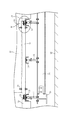
以下、本発明の好ましい実施の形態について添付図面を参照して説明する。まず図1から図5を参照して第1実施の形態について説明する。図1は第1実施の形態における二重床10の斜視図であり、図2は二重床10の平面図である。図3は図2のIII−III線における二重床10の断面図である。二重床10は、通信機器や電算機等の機器が搭載されるラック18を支持するための構造物であり、多くの通信機器や電算機等が収容されるデータセンター等に主に構築される。
Hereinafter, preferred embodiments of the present invention will be described with reference to the accompanying drawings. First, a first embodiment will be described with reference to FIGS. FIG. 1 is a perspective view of a
図1に示すように二重床10は、複数の支持脚11と、支持脚11に支持される第1梁12及び第2梁13と、第1梁12及び第2梁13にそれぞれ設けられる第1レール15及び第2レール16と、第1レール15及び第2レール16にスライド可能に固定される一対の架台17と、を備えている。固定部材21は、架台17間の隙間20(図2参照)にスライド可能に固定される。本実施の形態では、架台17間の隙間20に固定部材21が2本ずつ配置されている。一対の架台17及び固定部材21は、それらを一組として複数組(本実施の形態では6組)が配置されている。
As shown in FIG. 1, the
架台17に載置されるラック18は、固定部材21(図2参照)を用いて架台17に固定されている。通路を形成する床パネル19は第1梁12又は第2梁13に支持される。本実施の形態では、第1梁12と第2梁13との間に、支持脚11に支持された第3梁14が配置されている。第3梁14は、第1梁12及び第2梁13と共に架台17を支持する。架台17の下面には、架台17をスライドさせるときの第3梁14との抵抗を低減するため、ライナ(図示せず)が取り付けられている。図2に示すように第1梁12、第2梁13及び第3梁14は、互いに間隔をあけて平行に配置されている。
The
図3に示すように床スラブ22の上方に、大梁23と、大梁23に架設される小梁24とが配置されている。大梁23及び小梁24はいずれもH形鋼により形成されている。大梁23は、床スラブ22に配置された土台(図示せず)に支持される。支持脚11は、ボルト及びナットによって大梁23及び小梁24に固定されている。第1梁12、第2梁13及び第3梁14は、溝形鋼により形成されており、溝形鋼のフランジを下に向けて配置されている。
As shown in FIG. 3, a
図4は図3のIVで示す部分を拡大した二重床10の断面図である。なお、第1梁12及び第1レール15は、図4に示す第2梁13及び第2レール16と同様に構成されているので、第2梁13及び第2レール16について説明し、第1梁12及び第1レール15の説明は省略する。
4 is a cross-sectional view of the
図4に示すように第2梁13は、支持脚11の上部に結合する板状の受部30に、皿ボルト31及びナット32によって溝形鋼のウェブが固定される。第2梁13の上面に、第2レール16が配置される第1部33、床パネル19の一部が配置される第2部34、及び、架台17の一部が配置される第3部35が、第2梁13の短手方向(図4左右方向)に並んでいる。第2部34及び第3部35は、第1部33の短手方向の両側に位置する。
As shown in FIG. 4, in the
第2レール16はリップ溝形鋼からなり、長手方向(図4紙面垂直方向)を第2梁13の長手方向と一致させ、フランジを上に向けて第2梁13に載置されている。第2レール16は、第2レール16のウェブと第2梁13のウェブとを貫通する皿ボルト及び皿ボルトに締結するナット(いずれも図示せず)によって、第2梁13の第1部33に固定されている。
The
第2梁13の第2部34は、ライナ36を介して床パネル19の第1端部を支持する。床パネル19は、アルミニウム合金製の鋳造品であり機械的強度が高いので、床パネル19の第2端部を支持する支持脚(図示せず)との間に架設される。第2梁13の第3部35は、ライナ37を介して架台17の端を支持する。
The
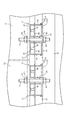
図5は図2のV−V線における二重床10の断面図である。図5に示すように架台17は、ラック18が載置される水平部38と、水平部38の長手方向に沿って水平部38に連接され下方へ延びる鉛直部39と、を備えている。本実施の形態では架台17は角形鋼管により形成されているので、一対の鉛直部39が水平部38の両側の縁に結合し、一対の鉛直部39の下縁同士を連結部40が連結する。ライナ37は、連結部40の長手方向の端部に固定されており、第2レール16に沿って架台17をスライドさせるときの第3部35(第2梁13)との抵抗を低減する。
FIG. 5 is a cross-sectional view of the
図4に戻って説明する。架台17は第2レール16の上に端部41が配置される。端部41は、水平部38に連接される上面部42と、鉛直部39に連接される一対の側面部43と、一対の側面部43の下縁に両側が接合され上面部42に対向する底面部44と、を備えている。本実施の形態では、角形鋼管の端の一部を切り取ることにより、水平部38、鉛直部39、連結部40、上面部42及び側面部43が作られる。
Returning to FIG. The
上面部42は、水平部38と共にラック18が載置される部位である。上面部42は、皿ボルト45の通る穴が、厚さ方向(図4上下方向)に貫通する。側面部43は、鉛直方向の荷重を受ける部位であり、架台17の長手方向(図4左右方向)における長さが、第2レール16の短手方向の幅よりもわずかに長い。底面部44は、第2レール16のフランジの上端に下面の一部が当たる板状の部材であり、側面部43の下縁に溶接されている。底面部44は、第2レール16のフランジに加える荷重を分散させ、側面部43及び第2レール16の座屈を防止する。底面部44は、皿ボルト45の通る穴が、厚さ方向(図4上下方向)に貫通する。
The
板部材46は、第2レール16のリップの下に配置される部材であり、皿ボルト45の通る穴が厚さ方向(図4上下方向)に貫通する。板部材46は、下面にナット47が接合されている。ナット47に皿ボルト45を締結すると、第2レール16のリップに板部材46が押し付けられて、端部41が第2レール16に固定される。皿ボルト45を緩めると、板部材46及びナット47が下降して板部材46が第2レール16のリップから離れるので、端部41は第2レール16をスライドできる。
The
端部41は第2レール16の上に載せられるので、架台17の上面17aの高さは、側面部43の高さに底面部44の厚さを加えた寸法によって決められる。側面部43及び底面部44の寸法は、床パネル19の上面19aと架台17の上面17aとが面一になるように設定される。その結果、架台17と床パネル19とに段差が生じないようにできるので、架台17と床パネル19との段差に人が躓かないようにできる。なお、第2梁13の第3部35と架台17との隙間は、ライナ37の厚さによって調整できる。
Since the
図5に示すように一対の架台17は、架台17間に、固定部材21が配置される隙間20が形成されている。本実施の形態では、固定部材21はボルト(軸状部材)からなる。固定部材21は、上端部および下端部が架台17の上下にそれぞれ突出し、架台17の下面に配置される第1板50、及び、架台17の上面に配置される第2板55を、ナット53,54により結合する。第1板50及び第2板55は、固定部材21の通る穴が、厚さ方向(図5上下方向)に貫通する。
As shown in FIG. 5, in the pair of
第1板50は、隙間20を隔てて並ぶ一対の架台17の連結部40に跨る座部51と、一対の架台17の外側の鉛直部39に沿って座部51の両端から上方へ突出する一対の突部52と、を備えている。鉛直部39に沿って突部52が突出するので、第1板50を架台17の短手方向(図5左右方向)へずれ難くできる。また、第1板50は、架台17間の隙間20の大きさ(幅)を規制する。第2板55は、架台17に載置されたラック18を水平部38との間に挟んで固定できる。ナット53,54を緩めることにより、架台17に沿って固定部材21をスライドできる。
The
以上のように二重床10は、架台17の端部41が第1レール15及び第2レール16にスライド可能に固定されている。一対の架台17の隙間20に配置される固定部材21は、架台17よりも上方に上端部が突出するので、架台17に載置されたラック18の固定に固定部材21を用いることができる。固定部材21は一対の架台17にスライド可能に固定されるので、ラック18の大きさや形状に応じて固定部材21の位置を可変にできる。
As described above, in the
隙間20の幅は、両端に突部52が形成された第1板50の座部51の長さによって上限値が定められるので、第1板50の座部51の長さを適宜設定することにより、隙間20の大きさを任意に設定できる。固定部材21は隙間20に挿入されるので、固定部材21の太さ(軸状部材の直径)を任意に設定できる。よって、ラック18の固定に用いられる固定部材21の選択肢を広くできる。また、第1板50及び第2板55によって、任意の本数の固定部材21を隙間20に配置できる。
Since the upper limit of the width of the
ラック18が上面17aに載置される架台17は、水平部38の長手方向に沿って水平部38に鉛直部39が連接されるので、架台17の軽量化を図りつつ架台17の強度を確保できる。一対の架台17及び固定部材21は、一対の架台17及び固定部材21を一組として複数組(少なくとも2組)が配置されるので、架台17と架台17との間にラック18を架設できる。架台17や床パネル19と床スラブ22との間に送風用ダクト(図示せず)を這わせてラック18のところまで延ばし、ラック18に搭載された電算機等の機器を冷却できる。
The
第1梁12及び第2梁13の上面の第1部33に第1レール15及び第2レール16がそれぞれ配置され、架台17の外側に位置する第2部34に床パネル19が配置される。ここで、第1梁12及び第2梁13に床パネル19を支持する第2部34を設けない場合には、第1梁12及び第2梁13に加えて、床パネル19を支持する支持脚11を別に設ける必要がある。しかし、第1梁12及び第2梁13の第2部34によって床パネル19を支持するので、その分の支持脚11を省略できる。よって、第1梁12及び第2梁13の一部(第2部34)で床パネル19を支持しない場合に比べて、支持脚11の本数を削減できる。
The
第1梁12及び第2梁13の第1部33を挟んで第2部34の反対側に第3部35が設けられており、鉛直部39及び連結部40の長手方向の端部は第3部35に支持される。その結果、鉛直部39及び連結部40の荷重を受ける第3部35が設けられていない場合に比べて、架台17の耐荷重を向上できる。
A
なお、架台17間に架設されたラック18とラック18との間には、ラック18に搭載された機器のメンテナンス等のときに通路として用いられる床パネル(図示せず)が配置される。床パネルは、架台17と同様に、第1レール15及び第2レール16の上に両端が載せられる。
A floor panel (not shown) that is used as a passage for maintenance of equipment mounted on the
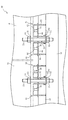
次に図6を参照して第2実施の形態について説明する。第1実施の形態では、角形鋼管によって架台17が形成される場合について説明した。これに対し第2実施の形態では、溝形鋼によって架台61が形成される二重床60について説明する。なお、第1実施の形態で説明した部分と同一の部分については、同一の符号を付して以下の説明を省略する。図6は第2実施の形態における二重床60の断面図である。
Next, a second embodiment will be described with reference to FIG. In 1st Embodiment, the case where the
図6に示すように二重床60は、第1梁12及び第2梁13にそれぞれ設けられる第1レール15及び第2レール16と、第1レール15及び第2レール16にスライド可能に固定される一対の架台61と、を備えている。架台61は溝形鋼により形成されており、溝形鋼のフランジ(鉛直部63)を下に向けて、第1レール15と第2レール16との間に配置されている。架台61は、ラック18が載置される水平部62と、水平部62の長手方向に沿って水平部62に連接される一対の鉛直部63と、を備えている。鉛直部63の長手方向の端部は、ライナ37(図4参照)を介して第1梁12及び第2梁13に支持される。
As shown in FIG. 6, the
一対の架台61の間に配置される固定部材21は、架台61の下に配置される第1板70、及び、架台61の上に配置される第2板55を、ナット53,54により結合する。第1板70は、固定部材21の通る穴が厚さ方向(図6上下方向)に貫通する。第1板70は、一対の架台61の内側の鉛直部63に跨る座部71と、鉛直部63に沿って座部71の両端から上方へ突出する一対の突部72と、を備えている。鉛直部63に沿って突部72が突出するので、第1板70を架台61の短手方向(図6左右方向)へずれ難くできる。
The fixing
二重床60によれば、第1実施の形態における二重床10と同様の作用効果を実現できる。溝形鋼を用いて架台61を形成するので、角形鋼管を用いる場合に比べて、架台61を軽量化できる。また、第1板70は、一対の架台61の内側の鉛直部63に座部71が跨るので、一対の架台61の外側の鉛直部63を座部が跨る場合に比べて、座部71の長さを短くできる。
According to the
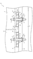
次に図7を参照して第3実施の形態について説明する。第2実施の形態では、溝形鋼によって架台61が形成される場合について説明した。これに対し第3実施の形態では、山形鋼によって架台81が形成される二重床80について説明する。なお、第1実施の形態で説明した部分と同一の部分については、同一の符号を付して以下の説明を省略する。図7は第3実施の形態における二重床80の断面図である。
Next, a third embodiment will be described with reference to FIG. In the second embodiment, the case where the
図7に示すように二重床80は、第1梁12及び第2梁13にそれぞれ設けられる第1レール15及び第2レール16と、第1レール15及び第2レール16にスライド可能に固定される一対の架台81と、を備えている。架台81は山形鋼により形成されており、ラック18が載置される水平部82と、水平部82の長手方向に沿って水平部82に連接される鉛直部83と、を備えている。
As shown in FIG. 7, the
架台81は、端部41(図4参照)に設けられる底面部44に側面部84が溶接されている。側面部84は、上面部42に溶接されている。架台81は、鉛直部83の長手方向の端部が、ライナ37(図4参照)を介して第1梁12及び第2梁13に支持される。
The
二重床80によれば、第1実施の形態における二重床10と同様の作用効果を実現できる。山形鋼を用いて架台81を形成するので、角形鋼管や溝形鋼を用いる場合に比べて、架台81を軽量化できる。
According to the
以上、実施の形態に基づき本発明を説明したが、本発明は上記実施の形態に何ら限定されるものではなく、本発明の趣旨を逸脱しない範囲内で種々の改良変形が可能であることは容易に推察できるものである。例えば、第1梁12、第2梁13、第1レール15、第2レール16及び架台17,61,81の形状や大きさ等は適宜設定できる。
The present invention has been described above based on the embodiments. However, the present invention is not limited to the above embodiments, and various improvements and modifications can be made without departing from the spirit of the present invention. It can be easily guessed. For example, the shape and size of the
上記各実施の形態では、床スラブ22に設けた大梁23及び小梁24に支持脚11をボルトによって固定する場合について説明したが、必ずしもこれに限られるものではない。大梁23及び小梁24を省略して、床スラブ22に支持脚11を固定し、その支持脚11に第1梁12及び第2梁13を支持させることは当然可能である。また、ボルトによって支持脚11を固定する代わりに、床スラブ22や大梁23及び小梁24に支持脚11を接着することは当然可能である。
In each of the above-described embodiments, the case where the
上記各実施の形態では、ボルト(軸状部材)によって固定部材21を構成する場合について説明したが、必ずしもこれに限られるものではない。板材やパイプによって固定部材21を形成することは当然可能である。また、板材に凹凸形状を付与して曲げ剛性を高めたものを固定部材21にすることは当然可能である。
In each of the above-described embodiments, the case where the fixing
上記各実施の形態では、形鋼を使って第1梁12、第2梁13、第1レール15、第2レール16及び架台17,61,81を形成する場合について説明したが、必ずしもこれに限られるものではない。第1梁12、第2梁13、第1レール15、第2レール16及び架台17,61,81は、金属製の板材が溶接されたもの、合成樹脂の一体成形品などを適宜採用できる。
In each of the above-described embodiments, the case where the
上記各実施の形態では、第1梁12及び第2梁13にそれぞれ第1レール15及び第2レール16が取り付けられる場合について説明した。これにより、二重床10,60,80を構築する現場に、第1梁12、第2梁13、第1レール15及び第2レール16を構成する資材を運び込み、現場で組み立てることができる。しかし、これに限られるものではない。第1梁12及び第1レール15、第2梁13及び第2レール16をそれぞれ一体成形品とすることは当然可能である。
In each of the above embodiments, the case where the
上記各実施の形態では、第1梁12と第2梁13との間に第3梁14を設ける場合について説明したが、必ずしもこれに限られるものではない。架台17,61,81の長さが短い場合等に、第3梁14を省略することは当然可能である。
In each of the above embodiments, the case where the
上記各実施の形態では、支持脚11の上端に第1梁12及び第2梁13を配置し、その第1梁12及び第2梁13に第1レール15及び第2レール16をそれぞれ設ける場合について説明したが、必ずしもこれに限られるものではない。支持脚11の高さの中間位置に第1梁12及び第2梁13を支持する部材を設け、その部材に支持された第1梁12及び第2梁13に第1レール15及び第2レール16をそれぞれ設けることは当然可能である。架台17,61,81は、第1レール15及び第2レール16に両端がスライド可能に固定され、架台17,61,81間に固定部材21がスライド可能に配置される。この場合、ラック18は支持脚11の上端の位置に支持される。ラック18の位置まで延びる固定部材21を用いることにより、固定部材21を使ってラック18を固定できる。
In each of the above embodiments, the
上記各実施の形態では、第2板55(板ワッシャ)によって、架台17,61,81との間にラック18を挟んでラック18を固定する場合について説明したが、必ずしもこれに限られるものではない。第2板55に代えて、ラック18固定用のブラケット(図示せず)を固定部材21に取り付け、そのブラケットとラック18とを結合し、ブラケットを介して固定部材21にラック18を固定することは当然可能である。
In each of the embodiments described above, the case where the
10,60,80 二重床
11 支持脚
12 第1梁
13 第2梁
15 第1レール
16 第2レール
17,61,81 架台
17a 上面
18 ラック
19 床パネル
19a 上面
20 隙間
21 固定部材
22 床スラブ
33 第1部
34 第2部
38,62,82 水平部
39,63,83 鉛直部
41 端部
10, 60, 80
Claims (4)
前記床スラブと前記床パネルとの間に配置される複数の支持脚と、
前記複数の支持脚に支持され互いに平行に配置される第1梁および第2梁と、
前記第1梁および前記第2梁と同じ向きに前記第1梁および前記第2梁にそれぞれ設けられる第1レール及び第2レールと、
前記第1レール及び前記第2レールに両端部がスライド可能に固定されると共に互いに隙間をあけて配置される一対の架台と、
前記一対の架台の前記隙間に配置されると共に前記一対の架台にスライド可能に固定され、前記一対の架台よりも上方に上端部が突出する固定部材と、を備えていることを特徴とする二重床。 A double floor in which a floor panel is arranged above the floor slab,
A plurality of support legs disposed between the floor slab and the floor panel;
A first beam and a second beam supported by the plurality of support legs and disposed parallel to each other;
A first rail and a second rail respectively provided on the first beam and the second beam in the same direction as the first beam and the second beam;
A pair of pedestals that are slidably fixed to the first rail and the second rail and arranged with a gap therebetween;
A fixing member disposed in the gap between the pair of mounts and slidably fixed to the pair of mounts and having an upper end projecting above the pair of mounts. Heavy floor.
前記水平部の長手方向に沿って前記水平部に連接される鉛直部と、を備え、
前記一対の架台および前記固定部材は、前記一対の架台および前記固定部材を一組として、複数組が配置されることを特徴とする請求項1記載の二重床。 The gantry includes a horizontal portion on which a rack on which equipment is mounted is placed on the upper surface;
A vertical portion connected to the horizontal portion along the longitudinal direction of the horizontal portion,
2. The double floor according to claim 1, wherein a plurality of sets of the pair of mounts and the fixing member are arranged with the pair of mounts and the fixing member as one set.
前記架台の外側に位置し前記床パネルが配置される第2部と、を備えていることを特徴とする請求項1又は2に記載の二重床。 The upper surfaces of the first beam and the second beam have a first portion on which the first rail and the second rail are respectively disposed;
The double floor according to claim 1, further comprising: a second portion that is located outside the mount and on which the floor panel is disposed.
Priority Applications (1)
| Application Number | Priority Date | Filing Date | Title |
|---|---|---|---|
| JP2016246119A JP6118944B1 (en) | 2016-12-20 | 2016-12-20 | Double floor |
Applications Claiming Priority (1)
| Application Number | Priority Date | Filing Date | Title |
|---|---|---|---|
| JP2016246119A JP6118944B1 (en) | 2016-12-20 | 2016-12-20 | Double floor |
Publications (2)
| Publication Number | Publication Date |
|---|---|
| JP6118944B1 JP6118944B1 (en) | 2017-04-19 |
| JP2018100511A true JP2018100511A (en) | 2018-06-28 |
Family
ID=58667228
Family Applications (1)
| Application Number | Title | Priority Date | Filing Date |
|---|---|---|---|
| JP2016246119A Expired - Fee Related JP6118944B1 (en) | 2016-12-20 | 2016-12-20 | Double floor |
Country Status (1)
| Country | Link |
|---|---|
| JP (1) | JP6118944B1 (en) |
Families Citing this family (1)
| Publication number | Priority date | Publication date | Assignee | Title |
|---|---|---|---|---|
| JP6994844B2 (en) * | 2017-05-02 | 2022-01-14 | 株式会社Nttファシリティーズ | Double floor structure |
Family Cites Families (2)
| Publication number | Priority date | Publication date | Assignee | Title |
|---|---|---|---|---|
| JP2511888Y2 (en) * | 1991-03-19 | 1996-09-25 | 株式会社アーレスティ | Fixing device for equipment on double floor |
| JP2005042411A (en) * | 2003-07-23 | 2005-02-17 | Sakura Technical:Kk | Computer floor fixing structure |
-
2016
- 2016-12-20 JP JP2016246119A patent/JP6118944B1/en not_active Expired - Fee Related
Also Published As
| Publication number | Publication date |
|---|---|
| JP6118944B1 (en) | 2017-04-19 |
Similar Documents
| Publication | Publication Date | Title |
|---|---|---|
| CN105620502B (en) | Central corridor floor support structure between a kind of railway vehicle device | |
| JP6118944B1 (en) | Double floor | |
| KR101658954B1 (en) | Light weight lattice shape-retaining double bottom structure of the floor | |
| KR20110076653A (en) | Structure bonding device and modular building including the same | |
| JP5341687B2 (en) | Free access floor mount | |
| JP5042811B2 (en) | Free access floor mount | |
| JP5042812B2 (en) | Free access floor mount | |
| JP6883836B2 (en) | Floor base structure and connecting bracket | |
| JP5486158B2 (en) | Double floor support legs and double floor structure | |
| JP5042815B2 (en) | Free access floor mount | |
| JP5715922B2 (en) | Free access floor mount | |
| JP5715920B2 (en) | Free access floor mount, free access floor mount installation structure | |
| KR101761277B1 (en) | Apparatus for horizontal buckling preventive structure of steel frame beam and steel frame beam including the same | |
| JP2008049927A (en) | Assembled cart frame | |
| JP6171889B2 (en) | Slide bearing member | |
| KR102640154B1 (en) | A reinforcing member for skid of steel packing | |
| JP2014058866A (en) | Unit building | |
| JP2013068054A (en) | Floor panel and floor using floor panel | |
| JP7573386B2 (en) | Structure for fixing objects | |
| JP5715921B2 (en) | Free access floor mount | |
| JP2009035374A (en) | Movable shelf unit | |
| JP5042814B2 (en) | Free access floor mount | |
| JP5079489B2 (en) | Free access floor mount | |
| JP4897380B2 (en) | Hanger rail mounting device for partition panel | |
| JP2018178510A (en) | Base-isolated structure |
Legal Events
| Date | Code | Title | Description |
|---|---|---|---|
| A621 | Written request for application examination |
Free format text: JAPANESE INTERMEDIATE CODE: A621 Effective date: 20170203 |
|
| A871 | Explanation of circumstances concerning accelerated examination |
Free format text: JAPANESE INTERMEDIATE CODE: A871 Effective date: 20170203 |
|
| A975 | Report on accelerated examination |
Free format text: JAPANESE INTERMEDIATE CODE: A971005 Effective date: 20170310 |
|
| TRDD | Decision of grant or rejection written | ||
| A01 | Written decision to grant a patent or to grant a registration (utility model) |
Free format text: JAPANESE INTERMEDIATE CODE: A01 Effective date: 20170321 |
|
| A61 | First payment of annual fees (during grant procedure) |
Free format text: JAPANESE INTERMEDIATE CODE: A61 Effective date: 20170327 |
|
| R150 | Certificate of patent or registration of utility model |
Ref document number: 6118944 Country of ref document: JP Free format text: JAPANESE INTERMEDIATE CODE: R150 |
|
| R250 | Receipt of annual fees |
Free format text: JAPANESE INTERMEDIATE CODE: R250 |
|
| R250 | Receipt of annual fees |
Free format text: JAPANESE INTERMEDIATE CODE: R250 |
|
| R250 | Receipt of annual fees |
Free format text: JAPANESE INTERMEDIATE CODE: R250 |
|
| LAPS | Cancellation because of no payment of annual fees |