JP2018106988A - Lighting fixture - Google Patents

Lighting fixture Download PDF

Info

Publication number
JP2018106988A
JP2018106988A JP2016253730A JP2016253730A JP2018106988A JP 2018106988 A JP2018106988 A JP 2018106988A JP 2016253730 A JP2016253730 A JP 2016253730A JP 2016253730 A JP2016253730 A JP 2016253730A JP 2018106988 A JP2018106988 A JP 2018106988A
Authority
JP
Japan
Prior art keywords
light source
top surface
drain hole
source chamber
chamber
Prior art date
Legal status (The legal status is an assumption and is not a legal conclusion. Google has not performed a legal analysis and makes no representation as to the accuracy of the status listed.)
Granted
Application number
JP2016253730A
Other languages
Japanese (ja)
Other versions
JP6834474B2 (en
Inventor
翔平 宮窪
Shohei Miyakubo
翔平 宮窪
慎平 遠藤
Shimpei Endo
慎平 遠藤
兼史 川尻
Kenji Kawajiri
兼史 川尻
毅 東藤
Tsuyoshi Todo
毅 東藤
Current Assignee (The listed assignees may be inaccurate. Google has not performed a legal analysis and makes no representation or warranty as to the accuracy of the list.)
Iwasaki Electric Co Ltd
Original Assignee
Iwasaki Electric Co Ltd
Priority date (The priority date is an assumption and is not a legal conclusion. Google has not performed a legal analysis and makes no representation as to the accuracy of the date listed.)
Filing date
Publication date
Application filed by Iwasaki Electric Co Ltd filed Critical Iwasaki Electric Co Ltd
Priority to JP2016253730A priority Critical patent/JP6834474B2/en
Publication of JP2018106988A publication Critical patent/JP2018106988A/en
Application granted granted Critical
Publication of JP6834474B2 publication Critical patent/JP6834474B2/en
Active legal-status Critical Current
Anticipated expiration legal-status Critical

Links

Images

Landscapes

  • Arrangement Of Elements, Cooling, Sealing, Or The Like Of Lighting Devices (AREA)
  • Non-Portable Lighting Devices Or Systems Thereof (AREA)

Abstract

【課題】氷柱形成の抑制を図った照明器具を提供する。【解決手段】器具本体10の内部に、光源部50を有する光源室58を備えた照明器具1において、光源室58の両脇に沿って、天面11Bから突出する突出部19が形成されており、突出部19の根元19Bには、器具本体10の天面11Bから底面11Aに連通する排水孔70が備えられている。【選択図】図6PROBLEM TO BE SOLVED: To provide a luminaire for suppressing icicle formation. SOLUTION: In a lighting fixture 1 provided with a light source chamber 58 having a light source portion 50 inside the fixture main body 10, a protruding portion 19 protruding from a top surface 11B is formed along both sides of the light source chamber 58. The base 19B of the protrusion 19 is provided with a drain hole 70 that communicates from the top surface 11B of the instrument body 10 to the bottom surface 11A. [Selection diagram] Fig. 6

Description

本発明は、照明器具に関する。   The present invention relates to a lighting fixture.

従来、LEDを光源とした街路灯や道路灯などの照明器具が知られている。これらの照明器具が積雪地帯で用いられた場合には、器具本体に積もった雪の雪解け水により器具本体から氷柱が形成される。そこで、従来から、氷柱が発生しにくい構成とした照明器具が知られている(例えば、特許文献1参照)。これらの照明器具では、LEDの発する熱を器具本体の下端部外面に伝達することで、下端部外面から垂れ落ちる雪解けの雫が凍って氷柱の根っことなる部分が器具本体に付着するのを防止している。   2. Description of the Related Art Conventionally, lighting fixtures such as street lights and road lights using LEDs as light sources are known. When these lighting fixtures are used in a snowy region, ice pillars are formed from the fixture main body by snow melting water accumulated on the fixture main body. Therefore, conventionally, there has been known a luminaire having a configuration in which an icy column is hardly generated (see, for example, Patent Document 1). In these lighting fixtures, the heat generated by the LEDs is transferred to the outer surface of the lower end of the fixture body, preventing the snowmelt dripping from the outer surface of the lower end portion from freezing and the root part of the icicle from sticking to the fixture body. doing.

特開2012−9166号公報JP 2012-9166 A

ところで、街路灯や道路灯などの照明器具は、基端部を電柱等の支柱に固定し、先端部が基端部よりも高くなるように斜めに傾斜して設置される。これにより、雪解け水は、器具本体の天面を先端部側から基端部側に向かって流れ、下端部となる基端部の外面から垂れ落ちる。LEDの発する熱を器具本体の基端部の外面に伝達させる構成では、器具本体の上部の積雪が多い場合には、器具本体の上部が低温となり、氷の層が形成される。このように、器具本体の上部に氷の層が形成された場合には、この氷の層から氷柱が形成される場合があった。   By the way, lighting fixtures, such as a street light and a road lamp, are installed inclining obliquely so that the base end is fixed to a support pole such as a power pole and the tip is higher than the base end. Thereby, the snow melting water flows from the distal end side toward the proximal end side on the top surface of the instrument body, and hangs down from the outer surface of the proximal end portion serving as the lower end portion. In the configuration in which the heat generated by the LED is transmitted to the outer surface of the base end portion of the instrument body, when there is a lot of snow on the upper part of the instrument body, the upper part of the instrument body becomes cold and an ice layer is formed. As described above, when an ice layer is formed on the upper part of the apparatus body, an ice column may be formed from the ice layer.

そこで本発明は、上述した事情に鑑みてなされたものであり、氷柱形成の抑制を図った照明器具を提供することを目的とする。   Then, this invention is made | formed in view of the situation mentioned above, and it aims at providing the lighting fixture which aimed at suppression of icicle formation.

本発明は、器具本体の内部に、光源部を有する光源室を備えた照明器具において、前記光源室の両脇に沿って、天面から突出する突出部が形成されており、前記突出部の根元には、前記器具本体の天面から底面に連通する排水孔が備えられていることを特徴とする。   The present invention provides a lighting fixture including a light source chamber having a light source portion inside the fixture main body, and protruding portions protruding from the top surface are formed along both sides of the light source chamber. The root is provided with a drainage hole communicating from the top surface to the bottom surface of the instrument body.

また、上記照明器具において、前記光源室の天面は、裏面に前記光源部が熱的に接続されていることを特徴としても良い。   Moreover, the said lighting fixture WHEREIN: The said light source part is thermally connected to the back surface of the top | upper surface of the said light source chamber, It is good also characterized by the above-mentioned.

また、上記照明器具において、前記突出部の上面は、前記器具本体の天面に向かって下方に傾斜していることを特徴としても良い。   Moreover, the said lighting fixture WHEREIN: The upper surface of the said protrusion part is good also as the downward inclination toward the top | upper surface of the said instrument main body, It is good also considering the above-mentioned.

また、上記照明器具において、前記突出部の内部に、前記光源部に電源を供給する電源部を配置したことを特徴としても良い。   Moreover, the said lighting fixture WHEREIN: The power supply part which supplies a power supply to the said light source part may be arrange | positioned inside the said protrusion part.

また、上記照明器具において、前記光源室の天面には、前記排水孔に向かって下方に傾斜するガイド部が設けられ、前記ガイド部は、前記天面の中央の側に向かって傾斜していることを特徴としても良い。   In the lighting apparatus, a guide portion that is inclined downward toward the drain hole is provided on a top surface of the light source chamber, and the guide portion is inclined toward a center side of the top surface. It may be characterized by being.

また、上記照明器具において、前記器具本体は、前記排水孔を挟んで前記光源室に対向する位置に結線室が設けられていることを特徴としても良い。   Moreover, the said lighting fixture WHEREIN: The said fixture main body is good also as the connection chamber being provided in the position which opposes the said light source chamber on both sides of the said drain hole.

また、上記照明器具において、前記排水孔は、当該排水孔を挟んで対向する前記光源室側の面と、前記結線室側の面とは、前記光源室側の面が、前記結線室側の面に比べて傾斜が緩やかに形成されていることを特徴としても良い。   Further, in the lighting apparatus, the drainage hole includes a surface on the light source chamber side facing the drainage hole and a surface on the connection chamber side, and the surface on the light source chamber side is on the connection chamber side. It may be characterized in that the slope is formed more gently than the surface.

また、上記照明器具において、前記排水孔は、前記結線室を塞ぐ蓋体で庇状に覆われていることを特徴としても良い。   Moreover, the said lighting fixture WHEREIN: The said drain hole is good also as characterized by being covered in the bowl shape with the cover body which plugs up the said connection room.

また、上記照明器具において、前記光源室の天面には、一対の前記突出部の根元にそれぞれ設けられた前記排水孔に向かうように水を分流させる分流部が設けられていることを特徴としても良い。   Further, in the above-mentioned lighting fixture, a diversion part for diverting water to be directed to the drainage holes provided at the bases of the pair of protrusions is provided on the top surface of the light source chamber. Also good.

また、上記照明器具において、前記排水孔は、当該排水孔を挟んで対向する前記光源室側の面と、前記結線室側の面とは、前記光源室側の面の下端部が、前記結線室側の面の下端部に比べて下方に位置することを特徴としても良い。   Further, in the above-described lighting apparatus, the drainage hole includes a surface on the light source chamber side facing the drainage hole and a surface on the connection chamber side, and a lower end portion of the surface on the light source chamber side is connected to the connection line. It is good also as being located below compared with the lower end part of the room side surface.

本発明では、光源室の両脇に沿って、天面から突出する突出部が形成されており、前記突出部の根元には、器具本体の天面から底面に連通する排水孔が備えられている。これによって、器具本体の側面、及び、排水孔から氷柱が発生するのを防ぐことができ、氷柱形成の抑制を図った照明器具を提供することができる。   In the present invention, a projecting portion that projects from the top surface is formed along both sides of the light source chamber, and a drainage hole that communicates from the top surface of the instrument body to the bottom surface is provided at the base of the projecting portion. Yes. Thereby, it is possible to prevent the ice column from being generated from the side surface of the device main body and the drain hole, and it is possible to provide a lighting device that suppresses the formation of the ice column.

本発明の実施形態に係る照明器具を下方からみた斜視図である。It is the perspective view which looked at the lighting fixture which concerns on embodiment of this invention from the downward direction. 照明器具を上方からみた斜視図である。It is the perspective view which looked at the lighting fixture from upper direction. 照明器具を下方から見た平面図である。It is the top view which looked at the lighting fixture from the downward direction. 照明器具の基部蓋体を開いた状態を示す斜視図である。It is a perspective view which shows the state which opened the base cover body of the lighting fixture. 図2のI−I断面図である。It is II sectional drawing of FIG. 筐体の天面を示す平面図である。It is a top view which shows the top | upper surface of a housing | casing. 図6のII−II断面図である。It is II-II sectional drawing of FIG. 図2のIII−III断面図である。It is III-III sectional drawing of FIG.

以下、図面を参照して本発明の実施形態について説明する。
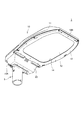
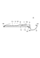
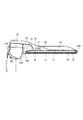
図1は本実施形態に係る照明器具1を下方からみた斜視図であり、図2は照明器具1を上方からみた斜視図である。図3は照明器具1を下方から見た平面図であり、照明器具1の内部を示すために、前面カバー12及び前面枠13を取り外した状態の照明器具1を示している。
Hereinafter, embodiments of the present invention will be described with reference to the drawings.
FIG. 1 is a perspective view of the luminaire 1 according to the present embodiment as viewed from below, and FIG. 2 is a perspective view of the luminaire 1 as viewed from above. FIG. 3 is a plan view of the luminaire 1 as viewed from below, and shows the luminaire 1 with the front cover 12 and the front frame 13 removed in order to show the inside of the luminaire 1.

照明器具1は、屋外に設置して、例えば道路照明として用いられる。図1〜図3に示すように、照明器具1は、器具本体10を備え、器具本体10の長手の一端である基端10Aを、道路脇、街路脇、駐車場、公園などの屋外に立設された不図示のポール型の支柱の上端部に支持させて設置される。照明器具1は、例えば、器具本体10の基端10Aから先端10B(他端)に向かう長さLの方向を道路の幅員方向に合わせて、幅Wの方向を道路の車線軸方向に合わせて、道路脇に設置される。また、照明器具1は、構造物の壁面からアーム状に延びる不図示の支持部材に器具本体10の基端10Aを支持させて設置されても良い。器具本体10の基端10Aの側には、照明器具1を支柱や支持部材に支持させるためのクランプ5が取り付けられている。   The luminaire 1 is installed outdoors and used, for example, as road lighting. As shown in FIGS. 1 to 3, the lighting apparatus 1 includes an apparatus main body 10, and a base end 10 </ b> A, which is one longitudinal end of the apparatus main body 10, stands outdoors on a roadside, a streetside, a parking lot, a park, or the like. It is installed by being supported on the upper end of a pole-shaped support (not shown). For example, the lighting device 1 is configured such that the direction of the length L from the base end 10A of the device body 10 toward the tip 10B (the other end) is matched with the width direction of the road, and the width W is matched with the lane axis direction of the road. Installed on the side of the road. Moreover, the lighting fixture 1 may be installed by supporting the base end 10 </ b> A of the fixture body 10 on a support member (not shown) extending in an arm shape from the wall surface of the structure. On the side of the base end 10 </ b> A of the fixture body 10, a clamp 5 for supporting the lighting fixture 1 on a support or a support member is attached.

器具本体10は、平面視略矩形状を成している。また、器具本体10は、長さLが幅Wよりも大きい縦長形状であり、上下方向の厚さTが、長さLや幅Wに対して薄い、薄型の器具である。なお、器具本体10の幅Wの方向を、照明器具1の左右方向として以下の説明をする。   The instrument body 10 has a substantially rectangular shape in plan view. In addition, the instrument body 10 is a thin instrument in which the length L is longer than the width W and the thickness T in the vertical direction is thinner than the length L and the width W. In addition, the following description will be made assuming that the direction of the width W of the fixture body 10 is the left-right direction of the lighting fixture 1.

器具本体10は、筐体11と、前面カバー12と、前面枠13と、を備えている。筐体11と、前面カバー12と、前面枠13と、は屋外使用に十分に耐え得る耐食性、及び強度を有する部材から形成されている。筐体11は、高い熱伝導性を有する材料から形成され、例えばアルミニウムやアルミニウム合金等から成る鋳造物(所謂ダイキャスト製)であるのが望ましい。筐体11は、その内部が器具本体10の基端10Aの側の結線室21と、先端10Bの側の光源室58とに仕切り56で仕切られている。結線室21には後述するクランプ5が配設され、光源室58には後述する光源部50が配設されている。   The instrument body 10 includes a housing 11, a front cover 12, and a front frame 13. The housing 11, the front cover 12, and the front frame 13 are formed of members having corrosion resistance and strength that can sufficiently withstand outdoor use. The casing 11 is formed of a material having high thermal conductivity, and is preferably a cast (so-called die-cast) made of, for example, aluminum or an aluminum alloy. The inside of the housing 11 is partitioned by a partition 56 into a connection chamber 21 on the proximal end 10A side of the instrument body 10 and a light source chamber 58 on the distal end 10B side. A clamp 5 described later is disposed in the connection chamber 21, and a light source unit 50 described later is disposed in the light source chamber 58.

前面カバー12は、耐食性、及び強度を有するガラスやポリカーボネート等の材料から形成され、光透過性を有している。前面枠13は、アルミニウムやアルミニウム合金等から成る鋳造物であっても良いし、耐食性、及び強度を有する強化プラスチック等の金属以外の材料から形成されていても良い。
器具本体10は、基端10Aの側に、基部20を備えている。基部20は、筐体11に一体に形成されている。基部20には、器具本体10を支柱や支持部材に取り付けるためのクランプ5が取り付けられている。
The front cover 12 is formed of a material such as glass or polycarbonate having corrosion resistance and strength, and has light transmittance. The front frame 13 may be a casting made of aluminum, an aluminum alloy, or the like, or may be formed of a material other than a metal such as reinforced plastic having corrosion resistance and strength.
The instrument main body 10 includes a base portion 20 on the base end 10A side. The base 20 is formed integrally with the housing 11. A clamp 5 for attaching the instrument main body 10 to a support column or a support member is attached to the base 20.

筐体11は、設置状態で被照射面に対向する面である底面11Aが開放した箱型に形成されている。光源室58は、筐体11の開放した底面11Aによって外部に露出される。前面カバー12は、筐体11の開放した底面11Aを覆い、光源室58の内部の防水を図るように構成されている。前面カバー12には、外輪の全周に沿ってパッキン18が取り付けられ、当該パッキン18によって前面カバー12と光源室58の内面との間が水密にシールされる。   The casing 11 is formed in a box shape in which a bottom surface 11A, which is a surface facing the irradiated surface in an installed state, is opened. The light source chamber 58 is exposed to the outside through the open bottom surface 11 </ b> A of the housing 11. The front cover 12 covers the open bottom surface 11 </ b> A of the housing 11 and is configured to waterproof the inside of the light source chamber 58. A packing 18 is attached to the front cover 12 along the entire circumference of the outer ring. The packing 18 seals the space between the front cover 12 and the inner surface of the light source chamber 58 in a watertight manner.

前面枠13は、筐体11の底面11Aに前面カバー12を固定するために用いられ、外輪形状が筐体11の外輪形状と略同一の枠状に形成されている。前面枠13には、前面カバー12を被照射面に臨ませる出射開口14が設けられている。パッキン18は、前面カバー12の外輪と、筐体11の内面との間に介在すると共に、筐体11の底面11Aと、前面枠13との間に介在するように構成された断面略U字状に形成されている。これにより、筐体11は、前面カバー12を前面枠13によって底面11Aに固定することで、底面11Aが閉塞され、光源室58の内部が防水される。   The front frame 13 is used to fix the front cover 12 to the bottom surface 11 </ b> A of the housing 11, and has an outer ring shape that is substantially the same as the outer ring shape of the housing 11. The front frame 13 is provided with an emission opening 14 that allows the front cover 12 to face the irradiated surface. The packing 18 is interposed between the outer ring of the front cover 12 and the inner surface of the housing 11, and has a substantially U-shaped cross section configured to be interposed between the bottom surface 11 </ b> A of the housing 11 and the front frame 13. It is formed in a shape. As a result, the housing 11 has the front cover 12 fixed to the bottom surface 11A by the front frame 13 so that the bottom surface 11A is closed and the inside of the light source chamber 58 is waterproofed.

器具本体10内には、図3に示すように光源部50が収められている。光源部50は、発光素子の一例であるLED53を光源として複数備えている。また、光源部50は、複数のLED53が実装された実装基板51と、LED53の光を制御する光学部材55とを備えている。光学部材55には、各LED53を覆って配置されるレンズ54が、各LED53に対応させて複数設けられている。光源部50は、発光面側を前面カバー12に対向させて配置されている。これによって、照明器具1は、光源部50からの光が前面カバー12を通して出射開口14から出射され、被照射面を照射するように構成されている。
また、筐体11の内部には、光源部50に並べて、電源部60が収められている。電源部60は、照明器具1の外部から供給される商用電力を、光源部50の規格に合せて電力変換する機器である。
A light source unit 50 is housed in the instrument body 10 as shown in FIG. The light source unit 50 includes a plurality of LEDs 53, which are examples of light emitting elements, as light sources. The light source unit 50 includes a mounting substrate 51 on which a plurality of LEDs 53 are mounted, and an optical member 55 that controls light from the LEDs 53. The optical member 55 is provided with a plurality of lenses 54 arranged so as to cover each LED 53 so as to correspond to each LED 53. The light source unit 50 is disposed with the light emitting surface side facing the front cover 12. Accordingly, the lighting fixture 1 is configured such that light from the light source unit 50 is emitted from the emission opening 14 through the front cover 12 and irradiates the irradiated surface.
In addition, a power supply unit 60 is housed inside the housing 11 in line with the light source unit 50. The power supply unit 60 is a device that converts commercial power supplied from the outside of the lighting fixture 1 in accordance with the standard of the light source unit 50.

図4は、基部20の内部構成を示す図である。図4に示すように、基部20は、中空箱型に形成され、内部空間が結線室21として構成されている。結線室21の内部では、クランプ5を通して基部20内に引き込まれた配線が器具本体10内に収められた光源部50及び電源部60からの配線と結線される。また、基部20には、結線室21を防水する蓋体22が設けられている。蓋体22は、筐体11の天面11Bに開閉可能に設けられている。結線室21は、蓋体22を開いた際には筐体11の天面11B側から外部に開放され、蓋体22を閉じた際には、内部が防水されるように構成されている。   FIG. 4 is a diagram illustrating an internal configuration of the base 20. As shown in FIG. 4, the base 20 is formed in a hollow box shape, and the internal space is configured as a connection chamber 21. Inside the connection chamber 21, the wiring drawn into the base 20 through the clamp 5 is connected to the wiring from the light source unit 50 and the power supply unit 60 housed in the instrument body 10. The base 20 is provided with a lid 22 that waterproofs the connection chamber 21. The lid 22 is provided on the top surface 11B of the housing 11 so as to be openable and closable. The connection chamber 21 is configured to be opened to the outside from the top surface 11B side of the housing 11 when the lid body 22 is opened, and to be waterproofed when the lid body 22 is closed.

図5は、照明器具1の断面図である。
図5に示すように、筐体11には、天面11Bに複数の放熱フィン16が設けられている。放熱フィン16は、天面11Bにおいて、筐体11の内部に光源部50が取り付けられる取付面15の裏面に相当する位置に複数設けられている。これによって、光源部50から取付面15に伝熱された熱は、取付面15の裏面部分に設けられた放熱フィン16に伝わりやすい構成となっており、放熱フィン16から雰囲気に放熱される。よって、光源部50が高温となることが無く、LED53が熱影響を受けにくい構成とすることができる。
FIG. 5 is a cross-sectional view of the luminaire 1.
As shown in FIG. 5, the housing 11 is provided with a plurality of heat radiation fins 16 on the top surface 11 </ b> B. A plurality of heat radiation fins 16 are provided on the top surface 11 </ b> B at positions corresponding to the back surface of the attachment surface 15 to which the light source unit 50 is attached inside the housing 11. Accordingly, the heat transferred from the light source unit 50 to the mounting surface 15 is easily transmitted to the heat radiation fins 16 provided on the back surface portion of the mounting surface 15 and is radiated from the heat radiation fins 16 to the atmosphere. Therefore, the light source unit 50 does not become high temperature, and the LED 53 can be configured to be hardly affected by heat.

筐体11の内側には、電源部60を収める凹部30が設けられている。凹部30は、筐体11の天面を取付面15に取り付けられた光源部50の光の放射方向とは反対側に凹ませて設けられている。凹部30は、取付面15の長さ方向の延在範囲に亘って延びている。
電源部60は、電源基板61と、電源基板61の表面に実装される複数種の電子部品62とから構成されている。電源基板61は、絶縁性を有する材料から長板状に形成されている。電源部60は、電源ケース63の内側に収められて、筐体11の内部に収容される。電源ケース63は、PP樹脂等の絶縁性を有する樹脂材から矩形筒状に形成されている。
A recess 30 that houses the power supply unit 60 is provided inside the housing 11. The recess 30 is provided by denting the top surface of the housing 11 to the opposite side of the light emission direction of the light source unit 50 attached to the attachment surface 15. The concave portion 30 extends over the extending range of the mounting surface 15 in the length direction.
The power supply unit 60 includes a power supply board 61 and a plurality of types of electronic components 62 mounted on the surface of the power supply board 61. The power supply substrate 61 is formed in a long plate shape from an insulating material. The power supply unit 60 is housed inside the power supply case 63 and is housed inside the housing 11. The power supply case 63 is formed in a rectangular cylindrical shape from an insulating resin material such as PP resin.

凹部30は、取付面15を間に挟んだ位置に一対設けられている。また、一対の凹部30は、筐体11の幅方向、つまり、照明器具1の車線軸方向に沿って取付面15と並べて、取付面15の両脇に設けられている。凹部30は、筐体11の天面11Bを膨出させて形成されており、筐体11の天面11Bには、左右の縁に沿って突出部19が設けられている。突出部19は、天面11Bよりも一段高く形成され、光源室58の長手に亘って延びている。   A pair of recesses 30 is provided at a position sandwiching the mounting surface 15 therebetween. Further, the pair of recesses 30 are provided on both sides of the mounting surface 15 so as to be aligned with the mounting surface 15 along the width direction of the housing 11, that is, the lane axis direction of the lighting fixture 1. The recess 30 is formed by expanding the top surface 11B of the housing 11, and the top surface 11B of the housing 11 is provided with protruding portions 19 along the left and right edges. The protruding portion 19 is formed one step higher than the top surface 11 </ b> B and extends over the length of the light source chamber 58.

このように、電源部60を収める凹部30を、車線軸方向に沿って並べて設けられているため、筐体11の長さLの寸法が大きくなるのを防ぐことができる。上述したように、照明器具1は器具本体10の基端10A側をクランプ5によって支持するため、筐体11の長さLの寸法が大きくなった場合には、クランプ5にかかる力(モーメント)が大きくなる。よって、筐体11の長さ寸法が大きくなるのを防ぐことで、クランプにかかる力を低減することができる。   Thus, since the recessed part 30 which accommodates the power supply part 60 is provided along with the lane axis direction, it can prevent that the dimension of the length L of the housing | casing 11 becomes large. As described above, since the lighting fixture 1 supports the base end 10A side of the fixture body 10 with the clamp 5, when the length L of the housing 11 is increased, the force (moment) applied to the clamp 5 is increased. Becomes larger. Therefore, the force applied to the clamp can be reduced by preventing the length of the casing 11 from increasing.

ところで、上述したように、器具本体10は、筐体11の天面11Bが平らな面であり、且つ、天面11Bには、この平らな面の左右の両縁に沿って突出部19が設けられているため、降雪時に上部に雪が積もりやすい。筐体11は、設置状態において、天面11Bが、先端10Bから基端10Aに向かって下方に傾斜している。このため、天面11Bの雨水や雪どけ水は、基端10Aの側に向かって流れる。   By the way, as above-mentioned, as for the instrument main body 10, the top | upper surface 11B of the housing | casing 11 is a flat surface, and the protrusion part 19 is formed in the top | upper surface 11B along the both right and left edges of this flat surface. Because it is provided, it is easy to accumulate snow at the top during snowfall. In the installed state, the top surface 11B of the housing 11 is inclined downward from the distal end 10B toward the proximal end 10A. For this reason, rain water and snow water on the top surface 11B flow toward the base end 10A.

突出部19は、光源室58の天面11Bに、左右の側縁に沿って土手状に延びている。また、突出部19の上面19Cは、筐体11の天面11Bに向かって斜め下方に傾斜する傾斜面となっている。突出部19の内部には、凹部30に電源部60が収められている。突出部19には、電源部60から熱が伝熱され、突出部19の上面19Cに積もった雪は、電源部60からの熱によって溶かされる。突出部19の上面Dで発生した雪解け水は、傾斜する上面19Cを沿って、天面11Bに流れる。この構成により、光源室58の天面11Bでは、雨水や雪どけ水が、光源室58の左右の側面19Aから垂れ落ちることがなく、天面11Bの上で基端10Aに向かって流れる。
なお、突出部は天面11Bの左右の側縁に加え先端10B側に設ける構成であっても良い。この構成により雨水や雪解け水は先端10Bから天面11Bに誘導され、先端10Bでの氷柱の発生を防ぐことができる。
The protrusion 19 extends in a bank shape along the left and right side edges on the top surface 11 </ b> B of the light source chamber 58. Further, the upper surface 19 </ b> C of the protruding portion 19 is an inclined surface that is inclined obliquely downward toward the top surface 11 </ b> B of the housing 11. Inside the protruding portion 19, the power supply unit 60 is housed in the recess 30. Heat is transferred from the power supply unit 60 to the protruding portion 19, and the snow accumulated on the upper surface 19 </ b> C of the protruding portion 19 is melted by the heat from the power supply portion 60. The snowmelt generated on the upper surface D of the protrusion 19 flows to the top surface 11B along the inclined upper surface 19C. With this configuration, on the top surface 11B of the light source chamber 58, rainwater or snow water does not drop from the left and right side surfaces 19A of the light source chamber 58 and flows toward the base end 10A on the top surface 11B.
In addition, the structure provided in the front-end | tip 10B side in addition to the left and right side edges of the top | upper surface 11B may be sufficient as a protrusion part. With this configuration, rainwater or snowmelt water is guided from the tip 10B to the top surface 11B, and the generation of ice pillars at the tip 10B can be prevented.

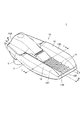
図6は、筐体11を天面11B側から見た平面図である。
図6に示すように、筐体11には、光源室58と結線室21との境目に、筐体11の天面11Bから底面11Aに連通する排水孔70が設けられている。排水孔70は、一対の突出部19の根元19Bにそれぞれ設けられている。排水孔70は、筐体11の略中央で光源室58と結線室21とを連結する連結部79を挟んだ位置に設けられている。連結部79には、蓋体22が取り付けられている。また、光源室58の天面11Bには、連結部79に突設された分流部80が設けられている。分流部80は、基端10Aの側に向かって上方に傾斜するスロープ状に天面11Bを隆起させて形成されている。筐体11の天面11Bの上を基端10Aの側に向かって流れる雨水や雪解け水は、分流部80の傾斜面によって、左右の排水孔70の夫々に向かう方向に分流される。
FIG. 6 is a plan view of the housing 11 as seen from the top surface 11B side.
As shown in FIG. 6, the housing 11 is provided with a drain hole 70 that communicates from the top surface 11 </ b> B of the housing 11 to the bottom surface 11 </ b> A at the boundary between the light source chamber 58 and the connection chamber 21. The drain holes 70 are respectively provided at the bases 19 </ b> B of the pair of projecting portions 19. The drain hole 70 is provided at a position sandwiching a connecting portion 79 that connects the light source chamber 58 and the connection chamber 21 at the approximate center of the housing 11. The lid 22 is attached to the connecting portion 79. In addition, a diverting portion 80 protruding from the connecting portion 79 is provided on the top surface 11 </ b> B of the light source chamber 58. The diversion part 80 is formed by raising the top surface 11B in a slope shape inclined upward toward the base end 10A. Rainwater and snowmelt flowing on the top surface 11 </ b> B of the housing 11 toward the base end 10 </ b> A are diverted in the direction toward the left and right drain holes 70 by the inclined surface of the diverter 80.

筐体11の天面11Bには、分流部80の両脇であって、分流部80と突出部19との間に、排水孔70に向かう排水路71が形成されている。筐体11の天面11Bの上を基端10Aの側に向かって流れる雨水や雪解け水は、分流部80によって左右の排水路71に導かれる。この構成によれば、天面11Bからの排水を、二つの排水孔70に分流させているため、排水されやすいどちらか一方の排水孔70から排水を行うことができる。また、排水路71に沿って流れる雨水や雪解け水は、土手状の突出部19によって左右の側面19Aから垂れ落ちることがない。なお、突出部19の根元19Bが排水孔70に向かって斜め下方に傾斜している構成であっても良い。   On the top surface 11 </ b> B of the housing 11, drainage channels 71 are formed on both sides of the flow dividing portion 80, and between the flow dividing portion 80 and the protruding portion 19, toward the drainage hole 70. Rainwater and snowmelt flowing on the top surface 11 </ b> B of the housing 11 toward the base end 10 </ b> A is guided to the left and right drainage channels 71 by the diverter 80. According to this configuration, since the drainage from the top surface 11B is divided into the two drainage holes 70, the drainage can be performed from either one of the drainage holes 70 that are easily drained. Moreover, the rainwater and the snowmelt flowing along the drainage channel 71 do not sag from the left and right side surfaces 19A by the bank-like protrusions 19. The base 19 </ b> B of the protrusion 19 may be inclined obliquely downward toward the drain hole 70.

排水路71には、排水孔70に向かって水を誘導するガイド部72が設けられている。ガイド部72は、排水路71から排水孔70に連続する面に設けられ、連結部79の側に向かって斜め下向きに形成された平面視略三角形の斜面である。排水路71を基端10Aの側に向かって流れる雨水や雪解け水は、ガイド部72によって、分流部80の根元の側から排水孔70に導かれる。
この構成によれば、筐体11の天面11Bにおいて、熱源である光源部50からの熱によって高温となる部分から雨水や雪解け水を排水することができる。よって、排水孔70から氷柱が発生するのを防止することができる。
The drainage channel 71 is provided with a guide portion 72 that guides water toward the drainage hole 70. The guide portion 72 is provided on a surface continuous from the drainage channel 71 to the drainage hole 70, and is a substantially triangular slope in a plan view formed obliquely downward toward the connecting portion 79 side. Rainwater and snowmelt flowing through the drainage channel 71 toward the base end 10 </ b> A side are guided from the base side of the diversion unit 80 to the drainage hole 70 by the guide unit 72.
According to this configuration, rainwater and snowmelt water can be drained from the portion of the top surface 11 </ b> B of the housing 11 that becomes high temperature due to heat from the light source unit 50 that is a heat source. Therefore, it is possible to prevent the ice column from being generated from the drain hole 70.

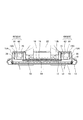
図7は、図6のII−II断面図である。図7に示すように、排水孔70は、光源室58の側の一方の内壁面73Aが、結線室21の側の他方の内壁面73Bよりも、天面11Bから底面11Aに向かう傾斜が緩やかになっている。この構成によれば、排水路71を流れる雨水や雪解け水は、光源室58の側の一方の内壁面73Aに沿って流れ、排水孔70から排水される。よって、排水路71を流れる雨水や雪解け水が、排水孔70に到達した際の勢いで結線室21の側の他方の内壁面73Bに当たって、他方の内壁面73Bを伝って落ちることがない。   7 is a cross-sectional view taken along the line II-II in FIG. As shown in FIG. 7, in the drain hole 70, one inner wall surface 73A on the light source chamber 58 side has a gentler slope from the top surface 11B to the bottom surface 11A than the other inner wall surface 73B on the connection chamber 21 side. It has become. According to this configuration, rainwater or snowmelt flowing through the drainage channel 71 flows along one inner wall surface 73 </ b> A on the light source chamber 58 side and is drained from the drainage hole 70. Therefore, rainwater or snowmelt water flowing through the drainage channel 71 hits the other inner wall surface 73B on the connection chamber 21 side by the momentum when reaching the drainage hole 70, and does not fall along the other inner wall surface 73B.

本実施形態において、器具本体10は先端10Bが上側となるように傾斜させて設置することがある。このとき、内壁面73Aが基端10A側に傾いた状態になると、ガイド部72からの雨水や雪解け水は、ガイド部72から内壁面73Aに伝わらない場合がある。したがって、内壁面73Aの水平面からの傾斜角度は、器具本体10を傾斜させた状態においても、基端10A側には傾斜しない角度で形成されている。
本実施形態においては、内壁面73Aの水平面からの傾斜角度は68°に形成されており、器具本体10の傾斜可能角度は20°に設定されており、器具本体10を傾斜させ設置した場合でも、内壁面73Aが基端10A側に傾斜することはない。
また、内壁面73Aの下端部は、内壁面72Bの下端部よりも下方に位置するように構成されている。この構成によれば、雨水や雪解け水は温度の高い内壁面73Aから排水されやすくなり氷柱の発生を抑えることができる。
本実施形態においては、内壁面73Aの下端部から内壁面73Bの下端部に結ぶ線の角度は21°に形成されている。この構成によれば、器具本体10を20°傾斜させた場合でも、73Aの下端部は73Bの下端部より下方に位置することとなる。
排水孔70は、光源室58の側の一方の内壁面73Aが光源部50からの熱によって高温となっている。これにより、排水孔70の一方の内壁面73Aに沿って雨水や雪解け水を排水させることで、排水孔70から氷柱が発生するのを防ぐことができる。
In the present embodiment, the instrument body 10 may be installed with an inclination so that the tip 10B is on the upper side. At this time, if the inner wall surface 73 </ b> A is inclined toward the base end 10 </ b> A, rainwater and snowmelt from the guide portion 72 may not be transmitted from the guide portion 72 to the inner wall surface 73 </ b> A. Therefore, the inclination angle of the inner wall surface 73A from the horizontal plane is formed at an angle that does not incline toward the base end 10A even when the instrument body 10 is inclined.
In the present embodiment, the angle of inclination of the inner wall surface 73A from the horizontal plane is formed at 68 °, the tiltable angle of the instrument main body 10 is set at 20 °, and even when the instrument main body 10 is tilted and installed. The inner wall surface 73A is not inclined toward the base end 10A.
Further, the lower end portion of the inner wall surface 73A is configured to be positioned below the lower end portion of the inner wall surface 72B. According to this configuration, rainwater and snowmelt can easily be drained from the inner wall surface 73A having a high temperature, and the generation of ice columns can be suppressed.
In the present embodiment, the angle of the line connecting the lower end portion of the inner wall surface 73A to the lower end portion of the inner wall surface 73B is formed at 21 °. According to this configuration, even when the instrument body 10 is inclined by 20 °, the lower end portion of 73A is positioned below the lower end portion of 73B.
In the drain hole 70, one inner wall surface 73 </ b> A on the light source chamber 58 side is heated by the heat from the light source unit 50. Thereby, it is possible to prevent the ice column from being generated from the drain hole 70 by draining rainwater or snowmelt water along the one inner wall surface 73 </ b> A of the drain hole 70.

排水孔70は、平面視での面積が少なくとも400mm程度であるのが望ましい。これにより、排水孔70にゴミ等の異物が詰まるのを抑制することができる。 The drain hole 70 preferably has an area of at least about 400 mm 2 in plan view. Thereby, it is possible to suppress the foreign matter such as dust from being clogged in the drain hole 70.

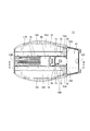
図8は、図2のIII−III断面図であり、蓋体22と排水孔70との位置関係を示す図である。図8に示すように、排水路71のガイド部72と、排水孔70と、は蓋体22によって庇状に覆われている。蓋体22は、排水路71を流れる雨水や雪解け水の流れを妨げることなく、排水孔70に導くように、排水路71との間に隙間Gを有している。また、この蓋体22と、排水路71との間の隙間Gは、排水路71を流れる雨水や雪解け水と共に、天面11Bの上のゴミ等の異物が排水孔70に流れ込まないように堰き止める機能を有している。よって蓋体22と、排水路71との間の隙間Gは、排水孔70の内壁面73Aの下端部と内壁面73Bの下端部の隙間よりも小さいほうが望ましい。   FIG. 8 is a cross-sectional view taken along the line III-III in FIG. 2 and shows the positional relationship between the lid 22 and the drain hole 70. As shown in FIG. 8, the guide portion 72 of the drainage channel 71 and the drainage hole 70 are covered with a lid 22 in a bowl shape. The lid 22 has a gap G between the lid 22 and the drainage channel 71 so as to guide it to the drainage hole 70 without hindering the flow of rainwater and snowmelt water flowing through the drainage channel 71. Further, the gap G between the lid body 22 and the drainage channel 71 is dammed so that foreign matter such as dust on the top surface 11B does not flow into the drainage hole 70 together with rainwater and snowmelt water flowing through the drainage channel 71. Has a function to stop. Therefore, the gap G between the lid 22 and the drainage channel 71 is preferably smaller than the gap between the lower end portion of the inner wall surface 73A of the drainage hole 70 and the lower end portion of the inner wall surface 73B.

このように、排水路71のガイド部72と、排水孔70と、を蓋体22で庇状に覆うことで、ガイド部72や排水孔70近傍の温度の低下を抑えることができる。これによって、排水孔70から氷柱が発生するのを抑制することができる。また、雪が直接に排水孔70に行くことが無く、排水孔70が積雪によって詰まるのを防ぐことができる。   Thus, by covering the guide portion 72 of the drainage channel 71 and the drainage hole 70 in a bowl shape with the lid body 22, it is possible to suppress a decrease in temperature in the vicinity of the guide portion 72 and the drainage hole 70. Thereby, it is possible to suppress the generation of ice columns from the drain hole 70. Further, the snow does not go directly to the drain hole 70, and the drain hole 70 can be prevented from being clogged with snow.

以上説明したように、本実施形態では、一端の側の結線室21と、他端の側の光源室58とに仕切られた器具本体10を備え、器具本体10は、光源室58の両脇に沿って、天面11Bから突出する突出部19を備え、突出部19の根元19Bであって、結線室21と光源室58との境界に、器具本体10の天面11Bから底面11Aに連通する排水孔70が備えられている。
この構成によれば、光源部50からの熱で熱くなっている光源室58の天面11Bから、器具本体10の中を通して、底面11Aに排水することができ、雪解け水が排水孔70を通る際に冷やされて排水孔70から氷柱が発生するのを防ぐことができる。また、突出部19によって、雪解け水が天面11Bから側面19Aに垂れることが無く、側面19Aからの氷柱の発生を防ぐことができる。
As described above, in the present embodiment, the instrument main body 10 that is partitioned into the connection chamber 21 on one end side and the light source chamber 58 on the other end side is provided, and the instrument main body 10 is provided on both sides of the light source chamber 58. The protrusion 19 protrudes from the top surface 11B, and is a base 19B of the protrusion 19 and communicates with the boundary between the connection chamber 21 and the light source chamber 58 from the top surface 11B of the instrument body 10 to the bottom surface 11A. A drain hole 70 is provided.
According to this configuration, water can be drained from the top surface 11 </ b> B of the light source chamber 58 heated by the heat from the light source unit 50 to the bottom surface 11 </ b> A through the instrument main body 10, and snow melting water passes through the drain hole 70. In this case, it is possible to prevent the ice column from being generated from the drain hole 70 by being cooled. Further, the protruding portion 19 prevents snow melting water from dripping from the top surface 11B to the side surface 19A, and can prevent the generation of icicles from the side surface 19A.

また、本実施形態では、光源室58の天面11Bは、裏面に光源部50が熱的に接続されており、排水孔70に向けて下方に傾斜している。この構成によれば、光源部50からの熱で熱くなっている天面11Bの上を伝って、排水孔70に向けて雪解け水を流すことができる。よって、雪解け水が天面11Bの上や、排水孔70の中で氷結することがなく、天面11Bや排水孔70から氷柱が発生するのを防ぐことができる。   In the present embodiment, the top surface 11 </ b> B of the light source chamber 58 has the light source unit 50 thermally connected to the back surface, and is inclined downward toward the drain hole 70. According to this configuration, the snow melting water can flow toward the drain hole 70 along the top surface 11 </ b> B that is heated by the heat from the light source unit 50. Therefore, it is possible to prevent icicles from being generated from the top surface 11B or the drain hole 70 without melting the snow melting on the top surface 11B or in the drain hole 70.

また、本実施形態では、突出部19の上面19Cは、器具本体10の天面11Bに向かって下方に傾斜している。この構成によれば、突出部19の上面19Cに積もった雪や、上面19Cの上で発生した雪解け水を天面11Bに導くことができる。よって、突出部19の上面19Cに積もった雪や、上面19Cの上で発生した雪解け水が突出部19の側面19Aの側から落下するのを防ぐことができる。よって、器具本体10からの、落雪や、氷柱の発生を抑制することができる。   In the present embodiment, the upper surface 19 </ b> C of the protrusion 19 is inclined downward toward the top surface 11 </ b> B of the instrument body 10. According to this configuration, snow accumulated on the upper surface 19C of the projecting portion 19 and snow melting water generated on the upper surface 19C can be guided to the top surface 11B. Therefore, it is possible to prevent the snow accumulated on the upper surface 19 </ b> C of the protruding portion 19 and the snow melting water generated on the upper surface 19 </ b> C from falling from the side surface 19 </ b> A side of the protruding portion 19. Therefore, it is possible to suppress the snowfall and the generation of icicles from the instrument body 10.

また、本実施形態では、光源室58の天面11Bには、排水孔70に向かって下方に傾斜するガイド部72が設けられ、ガイド部72は、天面11Bの中央の側に向かって傾斜している。この構成によれば、光源部50からの熱によって熱くなっている天面11Bから排水孔70に効率よく雪解け水を導くことができると共に、光源部50からの熱の影響が強い天面11Bの中央の側から排水孔70に雪解け水を流すことができる。よって、雪解け水が冷やされる前に排水孔70から排水させることができ、排水孔70から氷柱が発生するのを防ぐことができる。   In the present embodiment, the top surface 11B of the light source chamber 58 is provided with a guide portion 72 that is inclined downward toward the drain hole 70, and the guide portion 72 is inclined toward the center side of the top surface 11B. doing. According to this configuration, the snow melting water can be efficiently guided from the top surface 11B that is heated by the heat from the light source unit 50 to the drain hole 70, and the top surface 11B is strongly influenced by the heat from the light source unit 50. It is possible to flow snow melting water from the center side to the drain hole 70. Therefore, before the snowmelt water is cooled, the water can be drained from the drain hole 70, and an ice column can be prevented from being generated from the drain hole 70.

また、本実施形態では、排水孔70は、当該排水孔70を挟んで対向する光源室58の側の一方の内壁面73Aと、結線室21の側の他方の内壁面73Bとは、光源室58の側の一方の内壁面73Aが、結線室21の側の内壁面73Bに比べて傾斜が緩やかに形成されている。
また、器具本体10を傾斜させて設置した場合に、内壁面73Aが基端10Aの側に傾斜しない角度で形成されており、また、内壁面73Aの下端部が内壁面73Bの下端部より下方に位置するよう形成されている。
この構成によれば、光源部50からの熱によって熱くなっている光源室58の側の一方の内壁面73Aに沿って雪解け水を流して排水孔70から排水することができる。これによって、排水孔70から氷柱が発生するのを防ぐことができる。また、結線室21の側の他方の内壁面73Bの側に水が流れていくのを抑制することができ、結線室21の側の他方の内壁面73Bから氷柱が発生するのを防ぐことができる。
In the present embodiment, the drain hole 70 includes the one inner wall surface 73 </ b> A on the light source chamber 58 side facing the drain hole 70 and the other inner wall surface 73 </ b> B on the connection chamber 21 side in the light source chamber. One inner wall surface 73A on the 58 side is formed to have a gentler slope than the inner wall surface 73B on the connection chamber 21 side.
Further, when the instrument body 10 is installed at an inclination, the inner wall surface 73A is formed at an angle that does not incline toward the base end 10A, and the lower end portion of the inner wall surface 73A is lower than the lower end portion of the inner wall surface 73B. It is formed so that it may be located in.
According to this configuration, it is possible to drain snow from the drain hole 70 by flowing the snow melting water along the one inner wall surface 73 </ b> A on the light source chamber 58 side that is heated by the heat from the light source unit 50. Thereby, it is possible to prevent an ice column from being generated from the drain hole 70. Moreover, it can suppress that water flows into the other inner wall surface 73B side at the side of the connection chamber 21, and can prevent an ice column from being generated from the other inner wall surface 73B at the side of the connection chamber 21. it can.

また、本実施形態では、排水孔70は、結線室21を塞ぐ蓋体22で庇状に覆われている。この構成によれば、排水孔70の温度低下を防ぐことができ、排水孔70から氷柱が発生するのを防ぐことができる。また、排水孔70にゴミ等の異物が詰まるのを防ぐことができる。   In the present embodiment, the drain hole 70 is covered in a bowl shape with a lid 22 that closes the connection chamber 21. According to this configuration, the temperature drop of the drain hole 70 can be prevented, and the generation of icicles from the drain hole 70 can be prevented. Further, the drain hole 70 can be prevented from being clogged with foreign matters such as dust.

また、本実施形態では、光源室58の天面11Bには、一対の突出部19の根元19Bにそれぞれ設けられた排水孔70に向かうように水を分流させる分流部80が設けられている。この構成によれば、天面11Bの上を流れる雨水や雪解け水を二つの排水孔70に分けて排水することができる。よって、一方の排水孔70が詰まった場合であっても、他方の排水孔70から排水を行うことができる。   In the present embodiment, the top surface 11 </ b> B of the light source chamber 58 is provided with a diverter 80 that diverts water toward the drain holes 70 provided at the roots 19 </ b> B of the pair of protrusions 19. According to this configuration, rainwater and snowmelt flowing on the top surface 11B can be divided into the two drain holes 70 and drained. Therefore, even if one drain hole 70 is clogged, the other drain hole 70 can be drained.

また、本実施形態では、突出部19は、天面11Bを膨出させて形成され、内部に凹部30を備え、凹部30に光源部50に電源を供給する電源部60を配置した。この構成によれば、突出部19に電源部60からの熱を伝熱して、突出部19に積もった雪を融かすことができる。よって、突出部19から氷柱が発生するのを防ぐことができる。   In the present embodiment, the protrusion 19 is formed by expanding the top surface 11 </ b> B. According to this configuration, heat from the power supply unit 60 can be transferred to the projecting portion 19, and snow accumulated on the projecting portion 19 can be melted. Therefore, it is possible to prevent the ice column from being generated from the protrusion 19.

なお、上述した実施形態は、あくまでも本発明の一態様を例示するものであって、本発明の趣旨を逸脱しない範囲で任意に変形、及び応用が可能である。   The above-described embodiment is merely an example of the present invention, and can be arbitrarily modified and applied without departing from the spirit of the present invention.

例えば、上述した実施形態において、照明器具1を道路照明として用いる場合を例に説明したが、これに限らず、任意の照明器具に適用できる。   For example, in the above-described embodiment, the case where the lighting fixture 1 is used as road lighting has been described as an example. However, the present invention is not limited to this and can be applied to any lighting fixture.

また、上述した実施形態において、光源部50が備える発光素子の一例としてLED53を例示したが、発光素子は、LED53ではなく有機EL素子などの他の素子でもよい。   Moreover, in embodiment mentioned above, although LED53 was illustrated as an example of the light emitting element with which the light source part 50 is provided, other elements, such as an organic EL element instead of LED53, may be sufficient as a light emitting element.

また、上述した実施形態において、筐体11の天面11Bを膨出させて内部に凹部30を備えた突出部19を形成する構成を例示したが、これに限らず、突出部19は、内部に凹部30を有することなく天面11Bに設けられていても良い。   In the above-described embodiment, the configuration in which the top surface 11B of the housing 11 is bulged to form the protruding portion 19 having the recess 30 therein is not limited to this. It may be provided on the top surface 11 </ b> B without having the recess 30.

1 照明器具
10 器具本体
10A 基端
10B 先端
11 筐体
11A 底面
11B 天面
19 突出部
19A 側面
19B 根元
19C 上面
21 結線室
22 蓋体
30 凹部
50 光源部
58 光源室
60 電源部
70 排水孔
71 排水路
72 ガイド部
73A 内壁面
73B 内壁面
80 分流部
DESCRIPTION OF SYMBOLS 1 Lighting fixture 10 Appliance main body 10A Base end 10B Tip 11 Case 11A Bottom surface 11B Top surface 19 Projection portion 19A Side surface 19B Root 19C Top surface 21 Connection chamber 22 Lid 30 Recess 50 Light source portion 58 Light source chamber 60 Power source portion 70 Drain hole 71 Drain Road 72 Guide part 73A Inner wall surface 73B Inner wall surface 80 Dividing part

Claims (10)

器具本体の内部に、光源部を有する光源室を備えた照明器具において、
前記光源室の両脇に沿って、天面から突出する突出部が形成されており、
前記突出部の根元には、前記器具本体の天面から底面に連通する排水孔が備えられている
ことを特徴とする照明器具。
In a lighting fixture provided with a light source chamber having a light source portion inside the fixture body,
Protruding portions that protrude from the top surface are formed along both sides of the light source chamber,
A drainage hole that communicates from the top surface to the bottom surface of the fixture body is provided at the base of the protruding portion.
前記光源室の天面は、裏面に前記光源部が熱的に接続されていることを特徴とする請求項1に記載の照明器具。   The lighting apparatus according to claim 1, wherein the light source section is thermally connected to a back surface of the top surface of the light source chamber. 前記突出部の上面は、前記器具本体の天面に向かって下方に傾斜していることを特徴とする請求項1または2に記載の照明器具。   The lighting device according to claim 1, wherein an upper surface of the projecting portion is inclined downward toward a top surface of the device main body. 前記突出部の内部に、前記光源部に電源を供給する電源部を配置したことを特徴とする請求項1乃至3のいずれかに記載の照明器具。   The lighting apparatus according to claim 1, wherein a power supply unit that supplies power to the light source unit is disposed inside the protruding portion. 前記光源室の天面には、前記排水孔に向かって下方に傾斜するガイド部が設けられ、前記ガイド部は、前記天面の中央の側に向かって傾斜していることを特徴とする請求項1乃至4のいずれかに記載の照明器具。   The top surface of the light source chamber is provided with a guide portion that is inclined downward toward the drain hole, and the guide portion is inclined toward a center side of the top surface. Item 5. A lighting fixture according to any one of Items 1 to 4. 前記器具本体は、前記排水孔を挟んで前記光源室に対向する位置に結線室が設けられている
ことを特徴とする請求項1乃至5のいずれかに記載の照明器具。
The lighting fixture according to any one of claims 1 to 5, wherein the fixture main body is provided with a connection chamber at a position facing the light source chamber across the drain hole.
前記排水孔は、当該排水孔を挟んで対向する前記光源室側の面と、前記結線室側の面とは、前記光源室側の面が、前記結線室側の面に比べて傾斜が緩やかに形成されていることを特徴とする請求項6に記載の照明器具。   The surface of the light source chamber facing the surface of the drain hole and the surface of the connection chamber side of the drain hole are more inclined than the surface of the light source chamber than the surface of the connection chamber. The lighting fixture according to claim 6, wherein the lighting fixture is formed as follows. 前記排水孔は、前記結線室を塞ぐ蓋体で庇状に覆われていることを特徴とする請求項6または7に記載の照明器具。   The lighting apparatus according to claim 6 or 7, wherein the drain hole is covered in a bowl shape with a lid that closes the connection chamber. 前記光源室の天面には、一対の前記突出部の根元にそれぞれ設けられた前記排水孔に向かうように水を分流させる分流部が設けられていることを特徴とする請求項1乃至8のいずれかに記載の照明器具。   The top surface of the light source chamber is provided with a diversion part for diverting water so as to be directed to the drainage holes respectively provided at the bases of the pair of protrusions. The lighting fixture in any one. 前記排水孔は、当該排水孔を挟んで対向する前記光源室側の面と、前記結線室側の面とは、前記光源室側の面の下端部が、前記結線室側の面の下端部に比べて下方に位置することを特徴とする請求項6乃至9のいずれかに記載の照明器具。   The drain hole is a surface on the light source chamber side facing the drain hole, and a surface on the connection chamber side is a lower end portion of the surface on the light source chamber side, and a lower end portion of the surface on the connection chamber side. The luminaire according to claim 6, wherein the luminaire is positioned lower than the luminaire.
JP2016253730A 2016-12-27 2016-12-27 lighting equipment Active JP6834474B2 (en)

Priority Applications (1)

Application Number Priority Date Filing Date Title
JP2016253730A JP6834474B2 (en) 2016-12-27 2016-12-27 lighting equipment

Applications Claiming Priority (1)

Application Number Priority Date Filing Date Title
JP2016253730A JP6834474B2 (en) 2016-12-27 2016-12-27 lighting equipment

Publications (2)

Publication Number Publication Date
JP2018106988A true JP2018106988A (en) 2018-07-05
JP6834474B2 JP6834474B2 (en) 2021-02-24

Family

ID=62787893

Family Applications (1)

Application Number Title Priority Date Filing Date
JP2016253730A Active JP6834474B2 (en) 2016-12-27 2016-12-27 lighting equipment

Country Status (1)

Country Link
JP (1) JP6834474B2 (en)

Cited By (1)

* Cited by examiner, † Cited by third party
Publication number Priority date Publication date Assignee Title
JP2023020156A (en) * 2021-07-30 2023-02-09 パナソニックIpマネジメント株式会社 Lighting fixture, and luminaire

Citations (2)

* Cited by examiner, † Cited by third party
Publication number Priority date Publication date Assignee Title
JP2014093254A (en) * 2012-11-06 2014-05-19 Panasonic Corp Lighting device
EP2924335A1 (en) * 2014-03-27 2015-09-30 Simon, S.A.U. Outdoor luminaire

Patent Citations (2)

* Cited by examiner, † Cited by third party
Publication number Priority date Publication date Assignee Title
JP2014093254A (en) * 2012-11-06 2014-05-19 Panasonic Corp Lighting device
EP2924335A1 (en) * 2014-03-27 2015-09-30 Simon, S.A.U. Outdoor luminaire

Cited By (2)

* Cited by examiner, † Cited by third party
Publication number Priority date Publication date Assignee Title
JP2023020156A (en) * 2021-07-30 2023-02-09 パナソニックIpマネジメント株式会社 Lighting fixture, and luminaire
JP7706049B2 (en) 2021-07-30 2025-07-11 パナソニックIpマネジメント株式会社 Lighting fixtures and lighting equipment

Also Published As

Publication number Publication date
JP6834474B2 (en) 2021-02-24

Similar Documents

Publication Publication Date Title
US8382347B2 (en) Light fixture
RU2539363C2 (en) Outdoor lighting unit
JP5096424B2 (en) LED lighting device and heat dissipation waterproof cover thereof
US20140226331A1 (en) Light-fixture support assembly
JP2013051193A (en) Lighting device
KR101033874B1 (en) LED street light fixture with improved heat dissipation
KR101683585B1 (en) A street lighting
JP2018106988A (en) Lighting fixture
CN104949001B (en) Outdoor lamp
JP6217093B2 (en) Street light
KR101257033B1 (en) Led lighting instrument with excellent heat dispersing function
JP5966794B2 (en) lighting equipment
JP2012227017A (en) Lighting fixture
JP2017098112A (en) lighting equipment
JP2021096958A (en) Embedded type marker lamp
JP2011187304A (en) Light-emitting diode tunnel lighting fixture
JP6036119B2 (en) lighting equipment
JP6044237B2 (en) Cold district lighting fixtures
JP5479568B1 (en) LED lighting device
JP6623620B2 (en) lighting equipment
JP2018106990A (en) Lighting device
JP6766329B2 (en) Heat transport equipment and lighting equipment
JP6533392B2 (en) Lighting device
JP2017183263A (en) Lighting device
JP2006269236A (en) Outdoor lighting fixtures

Legal Events

Date Code Title Description
A621 Written request for application examination

Free format text: JAPANESE INTERMEDIATE CODE: A621

Effective date: 20191025

A977 Report on retrieval

Free format text: JAPANESE INTERMEDIATE CODE: A971007

Effective date: 20200915

A131 Notification of reasons for refusal

Free format text: JAPANESE INTERMEDIATE CODE: A131

Effective date: 20200929

A521 Request for written amendment filed

Free format text: JAPANESE INTERMEDIATE CODE: A523

Effective date: 20201023

TRDD Decision of grant or rejection written
A01 Written decision to grant a patent or to grant a registration (utility model)

Free format text: JAPANESE INTERMEDIATE CODE: A01

Effective date: 20210105

A61 First payment of annual fees (during grant procedure)

Free format text: JAPANESE INTERMEDIATE CODE: A61

Effective date: 20210118

R150 Certificate of patent or registration of utility model

Ref document number: 6834474

Country of ref document: JP

Free format text: JAPANESE INTERMEDIATE CODE: R150

S111 Request for change of ownership or part of ownership

Free format text: JAPANESE INTERMEDIATE CODE: R313111

R350 Written notification of registration of transfer

Free format text: JAPANESE INTERMEDIATE CODE: R350