JP2018119528A - 電動圧縮機 - Google Patents
電動圧縮機 Download PDFInfo
- Publication number
- JP2018119528A JP2018119528A JP2017013419A JP2017013419A JP2018119528A JP 2018119528 A JP2018119528 A JP 2018119528A JP 2017013419 A JP2017013419 A JP 2017013419A JP 2017013419 A JP2017013419 A JP 2017013419A JP 2018119528 A JP2018119528 A JP 2018119528A
- Authority
- JP
- Japan
- Prior art keywords
- refrigerant
- suction port
- electric motor
- electric compressor
- drive circuit
- Prior art date
- Legal status (The legal status is an assumption and is not a legal conclusion. Google has not performed a legal analysis and makes no representation as to the accuracy of the status listed.)
- Granted
Links
- 239000003507 refrigerant Substances 0.000 claims abstract description 129
- 230000006835 compression Effects 0.000 claims abstract description 31
- 238000007906 compression Methods 0.000 claims abstract description 31
- 238000005192 partition Methods 0.000 claims abstract description 18
- 230000002093 peripheral effect Effects 0.000 claims description 13
- WABPQHHGFIMREM-UHFFFAOYSA-N lead(0) Chemical compound [Pb] WABPQHHGFIMREM-UHFFFAOYSA-N 0.000 claims description 5
- 238000009833 condensation Methods 0.000 abstract description 10
- 230000005494 condensation Effects 0.000 abstract description 10
- 238000000638 solvent extraction Methods 0.000 abstract 1
- 229910052751 metal Inorganic materials 0.000 description 32
- 239000002184 metal Substances 0.000 description 32
- 238000003780 insertion Methods 0.000 description 13
- 230000037431 insertion Effects 0.000 description 13
- 238000001816 cooling Methods 0.000 description 12
- 230000004048 modification Effects 0.000 description 7
- 238000012986 modification Methods 0.000 description 7
- 239000011347 resin Substances 0.000 description 6
- 229920005989 resin Polymers 0.000 description 6
- 239000011810 insulating material Substances 0.000 description 4
- 238000004891 communication Methods 0.000 description 3
- 239000002826 coolant Substances 0.000 description 3
- 238000009413 insulation Methods 0.000 description 3
- 239000011295 pitch Substances 0.000 description 3
- 238000007789 sealing Methods 0.000 description 3
- 229910000831 Steel Inorganic materials 0.000 description 2
- 230000004323 axial length Effects 0.000 description 2
- 238000010030 laminating Methods 0.000 description 2
- 239000000696 magnetic material Substances 0.000 description 2
- 239000010959 steel Substances 0.000 description 2
- 229910052782 aluminium Inorganic materials 0.000 description 1
- XAGFODPZIPBFFR-UHFFFAOYSA-N aluminium Chemical compound [Al] XAGFODPZIPBFFR-UHFFFAOYSA-N 0.000 description 1
- 230000000903 blocking effect Effects 0.000 description 1
- 238000007664 blowing Methods 0.000 description 1
- 238000002485 combustion reaction Methods 0.000 description 1
- 238000006073 displacement reaction Methods 0.000 description 1
- 230000000694 effects Effects 0.000 description 1
- 239000012530 fluid Substances 0.000 description 1
- 239000000463 material Substances 0.000 description 1
- 239000007769 metal material Substances 0.000 description 1
- NJPPVKZQTLUDBO-UHFFFAOYSA-N novaluron Chemical compound C1=C(Cl)C(OC(F)(F)C(OC(F)(F)F)F)=CC=C1NC(=O)NC(=O)C1=C(F)C=CC=C1F NJPPVKZQTLUDBO-UHFFFAOYSA-N 0.000 description 1
- 239000013585 weight reducing agent Substances 0.000 description 1
Images




Classifications
-
- F—MECHANICAL ENGINEERING; LIGHTING; HEATING; WEAPONS; BLASTING
- F04—POSITIVE - DISPLACEMENT MACHINES FOR LIQUIDS; PUMPS FOR LIQUIDS OR ELASTIC FLUIDS
- F04B—POSITIVE-DISPLACEMENT MACHINES FOR LIQUIDS; PUMPS
- F04B35/00—Piston pumps specially adapted for elastic fluids and characterised by the driving means to their working members, or by combination with, or adaptation to, specific driving engines or motors, not otherwise provided for
- F04B35/04—Piston pumps specially adapted for elastic fluids and characterised by the driving means to their working members, or by combination with, or adaptation to, specific driving engines or motors, not otherwise provided for the means being electric
-
- F—MECHANICAL ENGINEERING; LIGHTING; HEATING; WEAPONS; BLASTING
- F04—POSITIVE - DISPLACEMENT MACHINES FOR LIQUIDS; PUMPS FOR LIQUIDS OR ELASTIC FLUIDS
- F04B—POSITIVE-DISPLACEMENT MACHINES FOR LIQUIDS; PUMPS
- F04B39/00—Component parts, details, or accessories, of pumps or pumping systems specially adapted for elastic fluids, not otherwise provided for in, or of interest apart from, groups F04B25/00 - F04B37/00
- F04B39/14—Provisions for readily assembling or disassembling
-
- F—MECHANICAL ENGINEERING; LIGHTING; HEATING; WEAPONS; BLASTING
- F04—POSITIVE - DISPLACEMENT MACHINES FOR LIQUIDS; PUMPS FOR LIQUIDS OR ELASTIC FLUIDS
- F04C—ROTARY-PISTON, OR OSCILLATING-PISTON, POSITIVE-DISPLACEMENT MACHINES FOR LIQUIDS; ROTARY-PISTON, OR OSCILLATING-PISTON, POSITIVE-DISPLACEMENT PUMPS
- F04C18/00—Rotary-piston pumps specially adapted for elastic fluids
- F04C18/02—Rotary-piston pumps specially adapted for elastic fluids of arcuate-engagement type, i.e. with circular translatory movement of co-operating members, each member having the same number of teeth or tooth-equivalents
- F04C18/0207—Rotary-piston pumps specially adapted for elastic fluids of arcuate-engagement type, i.e. with circular translatory movement of co-operating members, each member having the same number of teeth or tooth-equivalents both members having co-operating elements in spiral form
- F04C18/0215—Rotary-piston pumps specially adapted for elastic fluids of arcuate-engagement type, i.e. with circular translatory movement of co-operating members, each member having the same number of teeth or tooth-equivalents both members having co-operating elements in spiral form where only one member is moving
-
- F—MECHANICAL ENGINEERING; LIGHTING; HEATING; WEAPONS; BLASTING
- F04—POSITIVE - DISPLACEMENT MACHINES FOR LIQUIDS; PUMPS FOR LIQUIDS OR ELASTIC FLUIDS
- F04C—ROTARY-PISTON, OR OSCILLATING-PISTON, POSITIVE-DISPLACEMENT MACHINES FOR LIQUIDS; ROTARY-PISTON, OR OSCILLATING-PISTON, POSITIVE-DISPLACEMENT PUMPS
- F04C23/00—Combinations of two or more pumps, each being of rotary-piston or oscillating-piston type, specially adapted for elastic fluids; Pumping installations specially adapted for elastic fluids; Multi-stage pumps specially adapted for elastic fluids
- F04C23/008—Hermetic pumps
-
- F—MECHANICAL ENGINEERING; LIGHTING; HEATING; WEAPONS; BLASTING
- F04—POSITIVE - DISPLACEMENT MACHINES FOR LIQUIDS; PUMPS FOR LIQUIDS OR ELASTIC FLUIDS
- F04C—ROTARY-PISTON, OR OSCILLATING-PISTON, POSITIVE-DISPLACEMENT MACHINES FOR LIQUIDS; ROTARY-PISTON, OR OSCILLATING-PISTON, POSITIVE-DISPLACEMENT PUMPS
- F04C27/00—Sealing arrangements in rotary-piston pumps specially adapted for elastic fluids
- F04C27/008—Sealing arrangements in rotary-piston pumps specially adapted for elastic fluids for other than working fluid, i.e. the sealing arrangements are not between working chambers of the machine
-
- H—ELECTRICITY
- H02—GENERATION; CONVERSION OR DISTRIBUTION OF ELECTRIC POWER
- H02K—DYNAMO-ELECTRIC MACHINES
- H02K11/00—Structural association of dynamo-electric machines with electric components or with devices for shielding, monitoring or protection
- H02K11/30—Structural association with control circuits or drive circuits
- H02K11/33—Drive circuits, e.g. power electronics
-
- H—ELECTRICITY
- H02—GENERATION; CONVERSION OR DISTRIBUTION OF ELECTRIC POWER
- H02K—DYNAMO-ELECTRIC MACHINES
- H02K5/00—Casings; Enclosures; Supports
- H02K5/04—Casings or enclosures characterised by the shape, form or construction thereof
- H02K5/22—Auxiliary parts of casings not covered by groups H02K5/06-H02K5/20, e.g. shaped to form connection boxes or terminal boxes
- H02K5/225—Terminal boxes or connection arrangements
-
- H—ELECTRICITY
- H02—GENERATION; CONVERSION OR DISTRIBUTION OF ELECTRIC POWER
- H02K—DYNAMO-ELECTRIC MACHINES
- H02K7/00—Arrangements for handling mechanical energy structurally associated with dynamo-electric machines, e.g. structural association with mechanical driving motors or auxiliary dynamo-electric machines
- H02K7/14—Structural association with mechanical loads, e.g. with hand-held machine tools or fans
-
- F—MECHANICAL ENGINEERING; LIGHTING; HEATING; WEAPONS; BLASTING
- F04—POSITIVE - DISPLACEMENT MACHINES FOR LIQUIDS; PUMPS FOR LIQUIDS OR ELASTIC FLUIDS
- F04C—ROTARY-PISTON, OR OSCILLATING-PISTON, POSITIVE-DISPLACEMENT MACHINES FOR LIQUIDS; ROTARY-PISTON, OR OSCILLATING-PISTON, POSITIVE-DISPLACEMENT PUMPS
- F04C2240/00—Components
- F04C2240/40—Electric motor
-
- F—MECHANICAL ENGINEERING; LIGHTING; HEATING; WEAPONS; BLASTING
- F04—POSITIVE - DISPLACEMENT MACHINES FOR LIQUIDS; PUMPS FOR LIQUIDS OR ELASTIC FLUIDS
- F04C—ROTARY-PISTON, OR OSCILLATING-PISTON, POSITIVE-DISPLACEMENT MACHINES FOR LIQUIDS; ROTARY-PISTON, OR OSCILLATING-PISTON, POSITIVE-DISPLACEMENT PUMPS
- F04C2240/00—Components
- F04C2240/80—Other components
- F04C2240/808—Electronic circuits (e.g. inverters) installed inside the machine
Landscapes
- Engineering & Computer Science (AREA)
- Mechanical Engineering (AREA)
- General Engineering & Computer Science (AREA)
- Power Engineering (AREA)
- Microelectronics & Electronic Packaging (AREA)
- Compressor (AREA)
- Applications Or Details Of Rotary Compressors (AREA)
Abstract
Description
この場合、コイルエンドと冷媒吸入口が対向することで、コイルエンドと冷媒吸入口間のスペースを小さくして小型化できる一方で、部材の配置に制約を受けるが、電動モータ部であれば冷媒流を遮るように遮蔽部材を設けることができる。
この場合、係止体を電動モータ部に係止させることにより遮蔽部材を電動モータ部に設けることができる。
この場合、冷媒吸入口から吸入され、導電部材へ向けて流れる冷媒ガスの冷媒流を確実に遮ることができる。
この場合、係止体をステータコアから突出するコイルエンドに係止させることにより、遮蔽部材を電動モータ部に設けることができる。係止体をコイルエンドに係止することは、電動モータ部におけるコイルエンド以外に係止体を係止させる場合と比較するとより容易である。
この場合、係止片のコイルエンドへの係止ととともに当接片のコイルエンドの端面への当接により、コイルエンドからの遮蔽部材の脱落を防止することができる。
この場合、電動モータ部に設けられている遮蔽部材は、冷媒吸入口から吸入され、導電部材およびクラスタブロックへ向けて流れる冷媒ガスの冷媒流を遮るため、クラスタブロックの冷却に伴う導電部材の冷却が妨げられる。
この場合、遮蔽部材のクラスタブロックとの一体化により、部品点数を低減することができる。部品点数の低減により電動圧縮機の組み付け性を向上させることができる。
この場合、遮蔽部材がステータコアの溝に挿入されてステータコアに保持されることにより、遮蔽部材を電動モータ部に設けることができる。コイルエンドに遮蔽部材を設けることができない場合でも、遮蔽部材を電動モータ部に設けることができる。
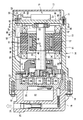
以下、第1の実施形態に係る電動圧縮機について図面を参照して説明する。本実施形態に係る電動圧縮機は、走行用の電動モータと内燃機関を走行駆動源とするハイブリッド車に搭載される車載用の電動圧縮機である。電動圧縮機は、車両用空調装置における冷媒回路の一部を構成している。車両用空調装置は、電動圧縮機のほか、図示はしないが、凝縮器としてのコンデンサと、レシーバと、膨張弁およびエバポレータを備えたクーリングユニットと、これらの機器を接続する配管を備えている。
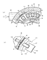
(1)電動モータ部12に設けられている遮蔽板65は、冷媒吸入口22から吸入され、金属端子51へ向けて流れる冷媒ガスの冷媒流を遮るため、金属端子51が直接冷媒流に晒されないことから、金属端子51の冷却が妨げられる。このため、金属端子51のモータ駆動回路部13側における結露を防止することができる。また、遮蔽板65は電動モータ部12におけるコイルエンド43に設けられている。遮蔽板65をコイルエンド43に設けることは、遮蔽板65をハウジング14に設ける場合と比較すると容易であり、電動圧縮機の組み付け性を向上させることができるとともに、ステータ33と底部20との間の限られたスペースに遮蔽板65を収容することができ、電動圧縮機の大型化を避けることができる。
(5)コイルエンド43と冷媒吸入口22が対向することで、コイルエンド43と冷媒吸入口22間のスペースを小さくして小型化できる一方で、部材の配置に制約を受けるが、電動モータ部12であれば冷媒流を遮るように遮蔽板65を設けることができる。
次に、第2の実施形態に係る電動圧縮機について説明する。本実施形態では、遮蔽部材がクラスタブロックと一体化されている点、第1の実施形態と異なる。本実施形態において第1の実施形態と同じ構成は、第1の実施形態の説明を援用し、符号を共通して用いる。
また、遮蔽部材81は、クラスタブロック55における冷媒吸入口22側に設けられている。このため、遮蔽部材81は、冷媒吸入口22から吸入され、金属端子51およびクラスタブロック55へ向けて流れる冷媒ガスの冷媒流を遮り、クラスタブロック55における冷媒吸入口22側の冷却を抑制する。
また、遮蔽部材81は、クラスタブロック55と一体形成されているため、遮蔽部材81のクラスタブロック55との一体化により、部品点数を低減することができる。部品点数の低減により電動圧縮機の組み付け性を向上させることができる。また、ステータ33と底部20との間の限られたスペース内に遮蔽部材81を収容することができ、電動圧縮機の大型化を避けることができる。
次に、第3の実施形態について説明する。本実施形態の電動圧縮機では、クラスタブロックがコイルエンドの外周側に設けられ、遮蔽部材の構成が第1の実施形態と異なる。本実施形態において第1の実施形態と同じ構成は、第1の実施形態の説明を援用し、符号を共通して用いる。
次に、第4の実施形態に係る電動圧縮機について説明する。本実施形態の電動圧縮機では、遮蔽部材としての遮蔽板がステータコアに設けられる点で第1の実施形態と異なる。本実施形態において第1の実施形態と同じ構成は、第1の実施形態の説明を援用し、符号を共通して用いる。
○ 上記の第2の実施形態では、遮蔽部材がクラスタブロックと一体化されたが、遮蔽部材はクラスタブロックと別部材であってもよい。また、第3の実施形態のクラスタブロックに遮蔽部材を設けるようにしてもよい。
○ 上記の第1の実施形態(変形例を含む)では、遮蔽部材が冷媒吸入口の開口面積よりも大きい面積を有したが、遮蔽部材の面積は、例えば、第3の実施形態の遮蔽部材のように、冷媒吸入口の開口面積よりも小さくてもよい。
○ 上記の第1、3、4の実施形態(変形例を含む)では、遮蔽部材としての遮蔽板を用いたが、遮蔽部材は板以外の形態であってもよい。また、遮蔽部材の形状は、冷媒流を妨げることが可能であれば、矩形に限らず自由である。
○ 上記の第1、4の実施形態(変形例を含む)では、遮蔽部材をコイルエンドの外周に設けたが、遮蔽部材をコイルエンドの内周に設けてもよい。
12 電動モータ部
13 モータ駆動回路部
14 ハウジング
22 冷媒吸入口
30 回転軸
33 ステータ
34 ロータ
35 ステータコア
36 コイル
43 コイルエンド
44 リード線
50 密封端子
51 金属端子(導電部材としての)
55、95 クラスタブロック
65、100、111 遮蔽板(遮蔽部材としての)
66、101、112 遮蔽板本体
67、102、113 係止体
74 当接片(変形例)
81 遮蔽部材
110 蟻溝
111 遮蔽板
G 隙間
P 軸線
Q 軸線
Claims (9)
- 回転軸の回転により冷媒を圧縮する圧縮部と、
コイルが巻回されるステータコアと、前記回転軸に連結されたロータとを備え、前記回転軸を介して前記圧縮部を駆動する電動モータ部と、
前記電動モータ部を駆動するモータ駆動回路部と、
前記圧縮部、前記電動モータ部および前記モータ駆動回路部を、この順で前記回転軸の軸方向に配置して収容するハウジングと、
前記ハウジングの一部として、前記電動モータ部と前記モータ駆動回路部を区画する区画壁と、
前記ハウジングにおいて前記圧縮部よりも前記区画壁寄りに設けられた冷媒吸入口と、
前記区画壁に設けられ、前記モータ駆動回路部と前記電動モータ部とを電気的に接続する導電部材と、を備えた電動圧縮機であって、
前記冷媒吸入口から前記導電部材への冷媒流を遮る遮蔽部材が、前記冷媒吸入口と前記導電部材との間に位置するように前記電動モータ部に設けられたことを特徴とする電動圧縮機。 - 前記冷媒吸入口は、前記ステータコアから突出するコイルエンドと対向するように配置されていることを特徴とする請求項1記載の電動圧縮機。
- 前記遮蔽部材は、
冷媒流を遮る遮蔽板本体と、
前記遮蔽板本体と一体形成され、前記電動モータ部と係止可能な係止体と、を備えていることを特徴とする請求項1又は2記載の電動圧縮機。 - 前記遮蔽板本体は、少なくとも前記冷媒吸入口の開口面積より大きい面積を有することを特徴とする請求項3記載の電動圧縮機。
- 前記係止体は、前記ステータコアから突出するコイルエンドに係止されることを特徴とする請求項3又は4記載の電動圧縮機。
- 前記遮蔽部材は、前記遮蔽板本体と一体形成され、前記コイルエンドの端面に当接可能な当接片を備えていることを特徴とする請求項5記載の電動圧縮機。
- 前記ハウジング内には、前記コイルから延びるリード線と前記導電部材とを電気的に接続する接続端子を有するクラスタブロックが設けられており、
前記遮蔽部材は、前記クラスタブロックと前記冷媒吸入口との間に設けられていることを特徴とする請求項1又は2記載の電動圧縮機。 - 前記遮蔽部材は、前記クラスタブロックと一体形成されていることを特徴とする請求項7記載の電動圧縮機。
- 前記ステータコアは、前記ステータコアの外周部に形成される溝を備え、
前記遮蔽部材は、前記溝に挿入されることにより前記ステータコアに保持されることを特徴とする請求項1〜4のいずれか一項記載の電動圧縮機。
Priority Applications (4)
| Application Number | Priority Date | Filing Date | Title |
|---|---|---|---|
| JP2017013419A JP6766666B2 (ja) | 2017-01-27 | 2017-01-27 | 電動圧縮機 |
| US15/863,439 US10738780B2 (en) | 2017-01-27 | 2018-01-05 | Electric compressor |
| KR1020180009285A KR101994913B1 (ko) | 2017-01-27 | 2018-01-25 | 전동 압축기 |
| DE102018101650.6A DE102018101650B4 (de) | 2017-01-27 | 2018-01-25 | Elektrischer kompressor |
Applications Claiming Priority (1)
| Application Number | Priority Date | Filing Date | Title |
|---|---|---|---|
| JP2017013419A JP6766666B2 (ja) | 2017-01-27 | 2017-01-27 | 電動圧縮機 |
Publications (2)
| Publication Number | Publication Date |
|---|---|
| JP2018119528A true JP2018119528A (ja) | 2018-08-02 |
| JP6766666B2 JP6766666B2 (ja) | 2020-10-14 |
Family
ID=62843621
Family Applications (1)
| Application Number | Title | Priority Date | Filing Date |
|---|---|---|---|
| JP2017013419A Active JP6766666B2 (ja) | 2017-01-27 | 2017-01-27 | 電動圧縮機 |
Country Status (4)
| Country | Link |
|---|---|
| US (1) | US10738780B2 (ja) |
| JP (1) | JP6766666B2 (ja) |
| KR (1) | KR101994913B1 (ja) |
| DE (1) | DE102018101650B4 (ja) |
Cited By (3)
| Publication number | Priority date | Publication date | Assignee | Title |
|---|---|---|---|---|
| JP2020165423A (ja) * | 2019-03-28 | 2020-10-08 | 株式会社豊田自動織機 | 電動圧縮機 |
| CN113464437A (zh) * | 2020-03-31 | 2021-10-01 | 株式会社丰田自动织机 | 电动压缩机 |
| WO2022202802A1 (ja) * | 2021-03-23 | 2022-09-29 | サンデン・オートモーティブコンポーネント株式会社 | 電動圧縮機 |
Families Citing this family (3)
| Publication number | Priority date | Publication date | Assignee | Title |
|---|---|---|---|---|
| CN106532994B (zh) * | 2016-12-14 | 2019-01-18 | 华南理工大学 | 基于3d相变热管技术的高导热车用电机定子组件 |
| JP6621114B2 (ja) * | 2018-02-21 | 2019-12-18 | 本田技研工業株式会社 | 回転電機 |
| US12237747B2 (en) | 2021-07-06 | 2025-02-25 | TE Connectivity Services Gmbh | Electrical connector with compression mounting clips |
Citations (3)
| Publication number | Priority date | Publication date | Assignee | Title |
|---|---|---|---|---|
| JP2005201108A (ja) * | 2004-01-14 | 2005-07-28 | Sanden Corp | 電動圧縮機 |
| JP2014009608A (ja) * | 2012-06-28 | 2014-01-20 | Toyota Industries Corp | 電動圧縮機 |
| JP2014034918A (ja) * | 2012-08-08 | 2014-02-24 | Toyota Industries Corp | 電動圧縮機 |
Family Cites Families (10)
| Publication number | Priority date | Publication date | Assignee | Title |
|---|---|---|---|---|
| GB2202905B (en) | 1987-03-12 | 1991-07-24 | Matsushita Electric Industrial Co Ltd | Scroll compressor |
| JPH0633785B2 (ja) | 1987-03-20 | 1994-05-02 | 松下電器産業株式会社 | 圧縮機 |
| JPH0278784A (ja) | 1988-09-14 | 1990-03-19 | Mitsubishi Electric Corp | 密閉形圧縮機 |
| JP2706516B2 (ja) | 1989-05-31 | 1998-01-28 | 松下電器産業株式会社 | 圧縮機 |
| JPH0893662A (ja) | 1994-09-20 | 1996-04-09 | Fujitsu General Ltd | スクロール圧縮機 |
| JP5505356B2 (ja) * | 2011-03-31 | 2014-05-28 | 株式会社豊田自動織機 | 電動圧縮機 |
| JP5423821B2 (ja) * | 2012-01-20 | 2014-02-19 | 株式会社豊田自動織機 | 電動圧縮機、及び電動圧縮機の製造方法 |
| JP6127797B2 (ja) * | 2012-10-02 | 2017-05-17 | 株式会社豊田自動織機 | 電動圧縮機 |
| JP6119962B2 (ja) * | 2012-11-15 | 2017-04-26 | 株式会社豊田自動織機 | 電動圧縮機 |
| JP6149429B2 (ja) * | 2013-03-06 | 2017-06-21 | 株式会社豊田自動織機 | スクロール型圧縮機 |
-
2017
- 2017-01-27 JP JP2017013419A patent/JP6766666B2/ja active Active
-
2018
- 2018-01-05 US US15/863,439 patent/US10738780B2/en active Active
- 2018-01-25 DE DE102018101650.6A patent/DE102018101650B4/de active Active
- 2018-01-25 KR KR1020180009285A patent/KR101994913B1/ko active Active
Patent Citations (3)
| Publication number | Priority date | Publication date | Assignee | Title |
|---|---|---|---|---|
| JP2005201108A (ja) * | 2004-01-14 | 2005-07-28 | Sanden Corp | 電動圧縮機 |
| JP2014009608A (ja) * | 2012-06-28 | 2014-01-20 | Toyota Industries Corp | 電動圧縮機 |
| JP2014034918A (ja) * | 2012-08-08 | 2014-02-24 | Toyota Industries Corp | 電動圧縮機 |
Cited By (7)
| Publication number | Priority date | Publication date | Assignee | Title |
|---|---|---|---|---|
| JP2020165423A (ja) * | 2019-03-28 | 2020-10-08 | 株式会社豊田自動織機 | 電動圧縮機 |
| JP7413753B2 (ja) | 2019-03-28 | 2024-01-16 | 株式会社豊田自動織機 | 電動圧縮機 |
| CN113464437A (zh) * | 2020-03-31 | 2021-10-01 | 株式会社丰田自动织机 | 电动压缩机 |
| WO2022202802A1 (ja) * | 2021-03-23 | 2022-09-29 | サンデン・オートモーティブコンポーネント株式会社 | 電動圧縮機 |
| JP2022147523A (ja) * | 2021-03-23 | 2022-10-06 | サンデン・オートモーティブコンポーネント株式会社 | 電動圧縮機 |
| US12404848B2 (en) | 2021-03-23 | 2025-09-02 | Sanden Corporation | Electric compressor |
| JP7743195B2 (ja) | 2021-03-23 | 2025-09-24 | サンデン株式会社 | 電動圧縮機 |
Also Published As
| Publication number | Publication date |
|---|---|
| DE102018101650B4 (de) | 2022-04-21 |
| JP6766666B2 (ja) | 2020-10-14 |
| KR20180088590A (ko) | 2018-08-06 |
| US10738780B2 (en) | 2020-08-11 |
| US20180216617A1 (en) | 2018-08-02 |
| KR101994913B1 (ko) | 2019-07-01 |
| DE102018101650A1 (de) | 2018-08-02 |
Similar Documents
| Publication | Publication Date | Title |
|---|---|---|
| JP6766666B2 (ja) | 電動圧縮機 | |
| JP5741346B2 (ja) | 電動圧縮機 | |
| US10707715B2 (en) | Motor-driven compressor | |
| CN101584100B (zh) | 定子、电动机以及压缩机 | |
| KR102625341B1 (ko) | 전동 압축기 | |
| KR100996744B1 (ko) | 모터 및 압축기 | |
| KR102289268B1 (ko) | 전동 압축기 | |
| US10396621B2 (en) | Electric compressor | |
| US20250038602A1 (en) | Stator of rotating electric machine | |
| US20250038608A1 (en) | Stator of rotating electric machine | |
| KR102689165B1 (ko) | 전동 압축기 | |
| EP2623786B1 (en) | Motor-driven compressor | |
| WO2023013433A1 (ja) | 電動圧縮機 | |
| JP6079463B2 (ja) | 電動圧縮機 | |
| JP4549968B2 (ja) | 電動圧縮機 | |
| JP7497698B2 (ja) | 流体機械 | |
| US20100254833A1 (en) | Terminal device for electric compressor | |
| CN115023881B (zh) | 马达、压缩机以及风扇马达 | |
| KR102003638B1 (ko) | 전동 압축기 | |
| JP2008082279A (ja) | 電動コンプレッサ | |
| US20250274018A1 (en) | Electric compressor | |
| US20260018956A1 (en) | Cluster block fixing structure, electric motor to which cluster block is mounted by the cluster block fixing structure, electric compressor having cluster block fixing structure, and air-conditioning apparatus, refrigerator, and on-vehicle apparatus having the electric compressor mounted thereto | |
| US20260018957A1 (en) | Cluster block, electric motor to which the cluster block is mounted, electric compressor having cluster block, and air-conditioning apparatus, refrigerator, and on-vehicle apparatus having the electric compressor mounted thereto | |
| KR20250125280A (ko) | 전동 압축기 | |
| US20260018958A1 (en) | Cluster block, electric motor to which the cluster block is mounted, electric compressor having cluster block, and air-conditioning apparatus, refrigerator, and on-vehicle apparatus having the electric compressor mounted thereto |
Legal Events
| Date | Code | Title | Description |
|---|---|---|---|
| A621 | Written request for application examination |
Free format text: JAPANESE INTERMEDIATE CODE: A621 Effective date: 20190408 |
|
| A977 | Report on retrieval |
Free format text: JAPANESE INTERMEDIATE CODE: A971007 Effective date: 20200120 |
|
| A131 | Notification of reasons for refusal |
Free format text: JAPANESE INTERMEDIATE CODE: A131 Effective date: 20200218 |
|
| A521 | Request for written amendment filed |
Free format text: JAPANESE INTERMEDIATE CODE: A523 Effective date: 20200408 |
|
| TRDD | Decision of grant or rejection written | ||
| A01 | Written decision to grant a patent or to grant a registration (utility model) |
Free format text: JAPANESE INTERMEDIATE CODE: A01 Effective date: 20200818 |
|
| A61 | First payment of annual fees (during grant procedure) |
Free format text: JAPANESE INTERMEDIATE CODE: A61 Effective date: 20200831 |
|
| R151 | Written notification of patent or utility model registration |
Ref document number: 6766666 Country of ref document: JP Free format text: JAPANESE INTERMEDIATE CODE: R151 |