JP2018123722A - Power transmission device with rotary machine - Google Patents
Power transmission device with rotary machine Download PDFInfo
- Publication number
- JP2018123722A JP2018123722A JP2017014996A JP2017014996A JP2018123722A JP 2018123722 A JP2018123722 A JP 2018123722A JP 2017014996 A JP2017014996 A JP 2017014996A JP 2017014996 A JP2017014996 A JP 2017014996A JP 2018123722 A JP2018123722 A JP 2018123722A
- Authority
- JP
- Japan
- Prior art keywords
- power transmission
- ring
- transmission device
- engagement
- gear
- Prior art date
- Legal status (The legal status is an assumption and is not a legal conclusion. Google has not performed a legal analysis and makes no representation as to the accuracy of the status listed.)
- Granted
Links
Images


Classifications
-
- B—PERFORMING OPERATIONS; TRANSPORTING
- B60—VEHICLES IN GENERAL
- B60K—ARRANGEMENT OR MOUNTING OF PROPULSION UNITS OR OF TRANSMISSIONS IN VEHICLES; ARRANGEMENT OR MOUNTING OF PLURAL DIVERSE PRIME-MOVERS IN VEHICLES; AUXILIARY DRIVES FOR VEHICLES; INSTRUMENTATION OR DASHBOARDS FOR VEHICLES; ARRANGEMENTS IN CONNECTION WITH COOLING, AIR INTAKE, GAS EXHAUST OR FUEL SUPPLY OF PROPULSION UNITS IN VEHICLES
- B60K6/00—Arrangement or mounting of plural diverse prime-movers for mutual or common propulsion, e.g. hybrid propulsion systems comprising electric motors and internal combustion engines
- B60K6/20—Arrangement or mounting of plural diverse prime-movers for mutual or common propulsion, e.g. hybrid propulsion systems comprising electric motors and internal combustion engines the prime-movers consisting of electric motors and internal combustion engines, e.g. HEVs
- B60K6/22—Arrangement or mounting of plural diverse prime-movers for mutual or common propulsion, e.g. hybrid propulsion systems comprising electric motors and internal combustion engines the prime-movers consisting of electric motors and internal combustion engines, e.g. HEVs characterised by apparatus, components or means specially adapted for HEVs
- B60K6/36—Arrangement or mounting of plural diverse prime-movers for mutual or common propulsion, e.g. hybrid propulsion systems comprising electric motors and internal combustion engines the prime-movers consisting of electric motors and internal combustion engines, e.g. HEVs characterised by apparatus, components or means specially adapted for HEVs characterised by the transmission gearings
- B60K6/365—Arrangement or mounting of plural diverse prime-movers for mutual or common propulsion, e.g. hybrid propulsion systems comprising electric motors and internal combustion engines the prime-movers consisting of electric motors and internal combustion engines, e.g. HEVs characterised by apparatus, components or means specially adapted for HEVs characterised by the transmission gearings with the gears having orbital motion
-
- F—MECHANICAL ENGINEERING; LIGHTING; HEATING; WEAPONS; BLASTING
- F02—COMBUSTION ENGINES; HOT-GAS OR COMBUSTION-PRODUCT ENGINE PLANTS
- F02N—STARTING OF COMBUSTION ENGINES; STARTING AIDS FOR SUCH ENGINES, NOT OTHERWISE PROVIDED FOR
- F02N15/00—Other power-operated starting apparatus; Component parts, details, or accessories, not provided for in, or of interest apart from groups F02N5/00 - F02N13/00
- F02N15/02—Gearing between starting-engines and started engines; Engagement or disengagement thereof
- F02N15/04—Gearing between starting-engines and started engines; Engagement or disengagement thereof the gearing including disengaging toothed gears
- F02N15/043—Gearing between starting-engines and started engines; Engagement or disengagement thereof the gearing including disengaging toothed gears the gearing including a speed reducer
- F02N15/046—Gearing between starting-engines and started engines; Engagement or disengagement thereof the gearing including disengaging toothed gears the gearing including a speed reducer of the planetary type
-
- B—PERFORMING OPERATIONS; TRANSPORTING
- B60—VEHICLES IN GENERAL
- B60K—ARRANGEMENT OR MOUNTING OF PROPULSION UNITS OR OF TRANSMISSIONS IN VEHICLES; ARRANGEMENT OR MOUNTING OF PLURAL DIVERSE PRIME-MOVERS IN VEHICLES; AUXILIARY DRIVES FOR VEHICLES; INSTRUMENTATION OR DASHBOARDS FOR VEHICLES; ARRANGEMENTS IN CONNECTION WITH COOLING, AIR INTAKE, GAS EXHAUST OR FUEL SUPPLY OF PROPULSION UNITS IN VEHICLES
- B60K6/00—Arrangement or mounting of plural diverse prime-movers for mutual or common propulsion, e.g. hybrid propulsion systems comprising electric motors and internal combustion engines
- B60K6/20—Arrangement or mounting of plural diverse prime-movers for mutual or common propulsion, e.g. hybrid propulsion systems comprising electric motors and internal combustion engines the prime-movers consisting of electric motors and internal combustion engines, e.g. HEVs
- B60K6/22—Arrangement or mounting of plural diverse prime-movers for mutual or common propulsion, e.g. hybrid propulsion systems comprising electric motors and internal combustion engines the prime-movers consisting of electric motors and internal combustion engines, e.g. HEVs characterised by apparatus, components or means specially adapted for HEVs
- B60K6/26—Arrangement or mounting of plural diverse prime-movers for mutual or common propulsion, e.g. hybrid propulsion systems comprising electric motors and internal combustion engines the prime-movers consisting of electric motors and internal combustion engines, e.g. HEVs characterised by apparatus, components or means specially adapted for HEVs characterised by the motors or the generators
-
- B—PERFORMING OPERATIONS; TRANSPORTING
- B60—VEHICLES IN GENERAL
- B60K—ARRANGEMENT OR MOUNTING OF PROPULSION UNITS OR OF TRANSMISSIONS IN VEHICLES; ARRANGEMENT OR MOUNTING OF PLURAL DIVERSE PRIME-MOVERS IN VEHICLES; AUXILIARY DRIVES FOR VEHICLES; INSTRUMENTATION OR DASHBOARDS FOR VEHICLES; ARRANGEMENTS IN CONNECTION WITH COOLING, AIR INTAKE, GAS EXHAUST OR FUEL SUPPLY OF PROPULSION UNITS IN VEHICLES
- B60K6/00—Arrangement or mounting of plural diverse prime-movers for mutual or common propulsion, e.g. hybrid propulsion systems comprising electric motors and internal combustion engines
- B60K6/20—Arrangement or mounting of plural diverse prime-movers for mutual or common propulsion, e.g. hybrid propulsion systems comprising electric motors and internal combustion engines the prime-movers consisting of electric motors and internal combustion engines, e.g. HEVs
- B60K6/22—Arrangement or mounting of plural diverse prime-movers for mutual or common propulsion, e.g. hybrid propulsion systems comprising electric motors and internal combustion engines the prime-movers consisting of electric motors and internal combustion engines, e.g. HEVs characterised by apparatus, components or means specially adapted for HEVs
- B60K6/38—Arrangement or mounting of plural diverse prime-movers for mutual or common propulsion, e.g. hybrid propulsion systems comprising electric motors and internal combustion engines the prime-movers consisting of electric motors and internal combustion engines, e.g. HEVs characterised by apparatus, components or means specially adapted for HEVs characterised by the driveline clutches
- B60K6/387—Actuated clutches, i.e. clutches engaged or disengaged by electric, hydraulic or mechanical actuating means
-
- B—PERFORMING OPERATIONS; TRANSPORTING
- B60—VEHICLES IN GENERAL
- B60K—ARRANGEMENT OR MOUNTING OF PROPULSION UNITS OR OF TRANSMISSIONS IN VEHICLES; ARRANGEMENT OR MOUNTING OF PLURAL DIVERSE PRIME-MOVERS IN VEHICLES; AUXILIARY DRIVES FOR VEHICLES; INSTRUMENTATION OR DASHBOARDS FOR VEHICLES; ARRANGEMENTS IN CONNECTION WITH COOLING, AIR INTAKE, GAS EXHAUST OR FUEL SUPPLY OF PROPULSION UNITS IN VEHICLES
- B60K6/00—Arrangement or mounting of plural diverse prime-movers for mutual or common propulsion, e.g. hybrid propulsion systems comprising electric motors and internal combustion engines
- B60K6/20—Arrangement or mounting of plural diverse prime-movers for mutual or common propulsion, e.g. hybrid propulsion systems comprising electric motors and internal combustion engines the prime-movers consisting of electric motors and internal combustion engines, e.g. HEVs
- B60K6/42—Arrangement or mounting of plural diverse prime-movers for mutual or common propulsion, e.g. hybrid propulsion systems comprising electric motors and internal combustion engines the prime-movers consisting of electric motors and internal combustion engines, e.g. HEVs characterised by the architecture of the hybrid electric vehicle
- B60K6/48—Parallel type
- B60K6/485—Motor-assist type
-
- F—MECHANICAL ENGINEERING; LIGHTING; HEATING; WEAPONS; BLASTING
- F02—COMBUSTION ENGINES; HOT-GAS OR COMBUSTION-PRODUCT ENGINE PLANTS
- F02N—STARTING OF COMBUSTION ENGINES; STARTING AIDS FOR SUCH ENGINES, NOT OTHERWISE PROVIDED FOR
- F02N11/00—Starting of engines by means of electric motors
- F02N11/04—Starting of engines by means of electric motors the motors being associated with current generators
- F02N11/06—Starting of engines by means of electric motors the motors being associated with current generators and with ignition apparatus
-
- F—MECHANICAL ENGINEERING; LIGHTING; HEATING; WEAPONS; BLASTING
- F02—COMBUSTION ENGINES; HOT-GAS OR COMBUSTION-PRODUCT ENGINE PLANTS
- F02N—STARTING OF COMBUSTION ENGINES; STARTING AIDS FOR SUCH ENGINES, NOT OTHERWISE PROVIDED FOR
- F02N15/00—Other power-operated starting apparatus; Component parts, details, or accessories, not provided for in, or of interest apart from groups F02N5/00 - F02N13/00
- F02N15/02—Gearing between starting-engines and started engines; Engagement or disengagement thereof
- F02N15/022—Gearing between starting-engines and started engines; Engagement or disengagement thereof the starter comprising an intermediate clutch
- F02N15/025—Gearing between starting-engines and started engines; Engagement or disengagement thereof the starter comprising an intermediate clutch of the friction type
-
- F—MECHANICAL ENGINEERING; LIGHTING; HEATING; WEAPONS; BLASTING
- F02—COMBUSTION ENGINES; HOT-GAS OR COMBUSTION-PRODUCT ENGINE PLANTS
- F02N—STARTING OF COMBUSTION ENGINES; STARTING AIDS FOR SUCH ENGINES, NOT OTHERWISE PROVIDED FOR
- F02N15/00—Other power-operated starting apparatus; Component parts, details, or accessories, not provided for in, or of interest apart from groups F02N5/00 - F02N13/00
- F02N15/02—Gearing between starting-engines and started engines; Engagement or disengagement thereof
- F02N15/022—Gearing between starting-engines and started engines; Engagement or disengagement thereof the starter comprising an intermediate clutch
- F02N15/027—Gearing between starting-engines and started engines; Engagement or disengagement thereof the starter comprising an intermediate clutch of the pawl type
-
- F—MECHANICAL ENGINEERING; LIGHTING; HEATING; WEAPONS; BLASTING
- F02—COMBUSTION ENGINES; HOT-GAS OR COMBUSTION-PRODUCT ENGINE PLANTS
- F02N—STARTING OF COMBUSTION ENGINES; STARTING AIDS FOR SUCH ENGINES, NOT OTHERWISE PROVIDED FOR
- F02N15/00—Other power-operated starting apparatus; Component parts, details, or accessories, not provided for in, or of interest apart from groups F02N5/00 - F02N13/00
- F02N15/02—Gearing between starting-engines and started engines; Engagement or disengagement thereof
- F02N15/08—Gearing between starting-engines and started engines; Engagement or disengagement thereof the gearing being of friction type
-
- F—MECHANICAL ENGINEERING; LIGHTING; HEATING; WEAPONS; BLASTING
- F16—ENGINEERING ELEMENTS AND UNITS; GENERAL MEASURES FOR PRODUCING AND MAINTAINING EFFECTIVE FUNCTIONING OF MACHINES OR INSTALLATIONS; THERMAL INSULATION IN GENERAL
- F16D—COUPLINGS FOR TRANSMITTING ROTATION; CLUTCHES; BRAKES
- F16D11/00—Clutches in which the members have interengaging parts
- F16D11/08—Clutches in which the members have interengaging parts actuated by moving a non-rotating part axially
- F16D11/10—Clutches in which the members have interengaging parts actuated by moving a non-rotating part axially with clutching members movable only axially
-
- F—MECHANICAL ENGINEERING; LIGHTING; HEATING; WEAPONS; BLASTING
- F16—ENGINEERING ELEMENTS AND UNITS; GENERAL MEASURES FOR PRODUCING AND MAINTAINING EFFECTIVE FUNCTIONING OF MACHINES OR INSTALLATIONS; THERMAL INSULATION IN GENERAL
- F16D—COUPLINGS FOR TRANSMITTING ROTATION; CLUTCHES; BRAKES
- F16D11/00—Clutches in which the members have interengaging parts
- F16D11/14—Clutches in which the members have interengaging parts with clutching members movable only axially
-
- F—MECHANICAL ENGINEERING; LIGHTING; HEATING; WEAPONS; BLASTING
- F16—ENGINEERING ELEMENTS AND UNITS; GENERAL MEASURES FOR PRODUCING AND MAINTAINING EFFECTIVE FUNCTIONING OF MACHINES OR INSTALLATIONS; THERMAL INSULATION IN GENERAL
- F16D—COUPLINGS FOR TRANSMITTING ROTATION; CLUTCHES; BRAKES
- F16D21/00—Systems comprising a plurality of actuated clutches
- F16D21/02—Systems comprising a plurality of actuated clutches for interconnecting three or more shafts or other transmission members in different ways
- F16D21/04—Systems comprising a plurality of actuated clutches for interconnecting three or more shafts or other transmission members in different ways with a shaft carrying a number of rotatable transmission members, e.g. gears, each of which can be connected to the shaft by a clutching member or members between the shaft and the hub of the transmission member
-
- F—MECHANICAL ENGINEERING; LIGHTING; HEATING; WEAPONS; BLASTING
- F16—ENGINEERING ELEMENTS AND UNITS; GENERAL MEASURES FOR PRODUCING AND MAINTAINING EFFECTIVE FUNCTIONING OF MACHINES OR INSTALLATIONS; THERMAL INSULATION IN GENERAL
- F16D—COUPLINGS FOR TRANSMITTING ROTATION; CLUTCHES; BRAKES
- F16D23/00—Details of mechanically-actuated clutches not specific for one distinct type
- F16D23/02—Arrangements for synchronisation, also for power-operated clutches
- F16D23/04—Arrangements for synchronisation, also for power-operated clutches with an additional friction clutch
- F16D23/06—Arrangements for synchronisation, also for power-operated clutches with an additional friction clutch and a blocking mechanism preventing the engagement of the main clutch prior to synchronisation
-
- F—MECHANICAL ENGINEERING; LIGHTING; HEATING; WEAPONS; BLASTING
- F16—ENGINEERING ELEMENTS AND UNITS; GENERAL MEASURES FOR PRODUCING AND MAINTAINING EFFECTIVE FUNCTIONING OF MACHINES OR INSTALLATIONS; THERMAL INSULATION IN GENERAL
- F16D—COUPLINGS FOR TRANSMITTING ROTATION; CLUTCHES; BRAKES
- F16D27/00—Magnetically- or electrically- actuated clutches; Control or electric circuits therefor
-
- F—MECHANICAL ENGINEERING; LIGHTING; HEATING; WEAPONS; BLASTING
- F16—ENGINEERING ELEMENTS AND UNITS; GENERAL MEASURES FOR PRODUCING AND MAINTAINING EFFECTIVE FUNCTIONING OF MACHINES OR INSTALLATIONS; THERMAL INSULATION IN GENERAL
- F16D—COUPLINGS FOR TRANSMITTING ROTATION; CLUTCHES; BRAKES
- F16D67/00—Combinations of couplings and brakes; Combinations of clutches and brakes
- F16D67/02—Clutch-brake combinations
-
- F—MECHANICAL ENGINEERING; LIGHTING; HEATING; WEAPONS; BLASTING
- F16—ENGINEERING ELEMENTS AND UNITS; GENERAL MEASURES FOR PRODUCING AND MAINTAINING EFFECTIVE FUNCTIONING OF MACHINES OR INSTALLATIONS; THERMAL INSULATION IN GENERAL
- F16H—GEARING
- F16H3/00—Toothed gearings for conveying rotary motion with variable gear ratio or for reversing rotary motion
- F16H3/44—Toothed gearings for conveying rotary motion with variable gear ratio or for reversing rotary motion using gears having orbital motion
-
- F—MECHANICAL ENGINEERING; LIGHTING; HEATING; WEAPONS; BLASTING
- F16—ENGINEERING ELEMENTS AND UNITS; GENERAL MEASURES FOR PRODUCING AND MAINTAINING EFFECTIVE FUNCTIONING OF MACHINES OR INSTALLATIONS; THERMAL INSULATION IN GENERAL
- F16H—GEARING
- F16H57/00—General details of gearing
- F16H57/08—General details of gearing of gearings with members having orbital motion
- F16H57/10—Braking arrangements
-
- H—ELECTRICITY
- H02—GENERATION; CONVERSION OR DISTRIBUTION OF ELECTRIC POWER
- H02K—DYNAMO-ELECTRIC MACHINES
- H02K7/00—Arrangements for handling mechanical energy structurally associated with dynamo-electric machines, e.g. structural association with mechanical driving motors or auxiliary dynamo-electric machines
- H02K7/10—Structural association with clutches, brakes, gears, pulleys or mechanical starters
- H02K7/116—Structural association with clutches, brakes, gears, pulleys or mechanical starters with gears
-
- B—PERFORMING OPERATIONS; TRANSPORTING
- B60—VEHICLES IN GENERAL
- B60K—ARRANGEMENT OR MOUNTING OF PROPULSION UNITS OR OF TRANSMISSIONS IN VEHICLES; ARRANGEMENT OR MOUNTING OF PLURAL DIVERSE PRIME-MOVERS IN VEHICLES; AUXILIARY DRIVES FOR VEHICLES; INSTRUMENTATION OR DASHBOARDS FOR VEHICLES; ARRANGEMENTS IN CONNECTION WITH COOLING, AIR INTAKE, GAS EXHAUST OR FUEL SUPPLY OF PROPULSION UNITS IN VEHICLES
- B60K6/00—Arrangement or mounting of plural diverse prime-movers for mutual or common propulsion, e.g. hybrid propulsion systems comprising electric motors and internal combustion engines
- B60K6/20—Arrangement or mounting of plural diverse prime-movers for mutual or common propulsion, e.g. hybrid propulsion systems comprising electric motors and internal combustion engines the prime-movers consisting of electric motors and internal combustion engines, e.g. HEVs
- B60K6/22—Arrangement or mounting of plural diverse prime-movers for mutual or common propulsion, e.g. hybrid propulsion systems comprising electric motors and internal combustion engines the prime-movers consisting of electric motors and internal combustion engines, e.g. HEVs characterised by apparatus, components or means specially adapted for HEVs
- B60K6/26—Arrangement or mounting of plural diverse prime-movers for mutual or common propulsion, e.g. hybrid propulsion systems comprising electric motors and internal combustion engines the prime-movers consisting of electric motors and internal combustion engines, e.g. HEVs characterised by apparatus, components or means specially adapted for HEVs characterised by the motors or the generators
- B60K2006/268—Electric drive motor starts the engine, i.e. used as starter motor
-
- B—PERFORMING OPERATIONS; TRANSPORTING
- B60—VEHICLES IN GENERAL
- B60K—ARRANGEMENT OR MOUNTING OF PROPULSION UNITS OR OF TRANSMISSIONS IN VEHICLES; ARRANGEMENT OR MOUNTING OF PLURAL DIVERSE PRIME-MOVERS IN VEHICLES; AUXILIARY DRIVES FOR VEHICLES; INSTRUMENTATION OR DASHBOARDS FOR VEHICLES; ARRANGEMENTS IN CONNECTION WITH COOLING, AIR INTAKE, GAS EXHAUST OR FUEL SUPPLY OF PROPULSION UNITS IN VEHICLES
- B60K6/00—Arrangement or mounting of plural diverse prime-movers for mutual or common propulsion, e.g. hybrid propulsion systems comprising electric motors and internal combustion engines
- B60K6/20—Arrangement or mounting of plural diverse prime-movers for mutual or common propulsion, e.g. hybrid propulsion systems comprising electric motors and internal combustion engines the prime-movers consisting of electric motors and internal combustion engines, e.g. HEVs
- B60K6/22—Arrangement or mounting of plural diverse prime-movers for mutual or common propulsion, e.g. hybrid propulsion systems comprising electric motors and internal combustion engines the prime-movers consisting of electric motors and internal combustion engines, e.g. HEVs characterised by apparatus, components or means specially adapted for HEVs
- B60K6/38—Arrangement or mounting of plural diverse prime-movers for mutual or common propulsion, e.g. hybrid propulsion systems comprising electric motors and internal combustion engines the prime-movers consisting of electric motors and internal combustion engines, e.g. HEVs characterised by apparatus, components or means specially adapted for HEVs characterised by the driveline clutches
- B60K2006/381—Arrangement or mounting of plural diverse prime-movers for mutual or common propulsion, e.g. hybrid propulsion systems comprising electric motors and internal combustion engines the prime-movers consisting of electric motors and internal combustion engines, e.g. HEVs characterised by apparatus, components or means specially adapted for HEVs characterised by the driveline clutches characterized by driveline brakes
-
- B—PERFORMING OPERATIONS; TRANSPORTING
- B60—VEHICLES IN GENERAL
- B60K—ARRANGEMENT OR MOUNTING OF PROPULSION UNITS OR OF TRANSMISSIONS IN VEHICLES; ARRANGEMENT OR MOUNTING OF PLURAL DIVERSE PRIME-MOVERS IN VEHICLES; AUXILIARY DRIVES FOR VEHICLES; INSTRUMENTATION OR DASHBOARDS FOR VEHICLES; ARRANGEMENTS IN CONNECTION WITH COOLING, AIR INTAKE, GAS EXHAUST OR FUEL SUPPLY OF PROPULSION UNITS IN VEHICLES
- B60K6/00—Arrangement or mounting of plural diverse prime-movers for mutual or common propulsion, e.g. hybrid propulsion systems comprising electric motors and internal combustion engines
- B60K6/20—Arrangement or mounting of plural diverse prime-movers for mutual or common propulsion, e.g. hybrid propulsion systems comprising electric motors and internal combustion engines the prime-movers consisting of electric motors and internal combustion engines, e.g. HEVs
- B60K6/42—Arrangement or mounting of plural diverse prime-movers for mutual or common propulsion, e.g. hybrid propulsion systems comprising electric motors and internal combustion engines the prime-movers consisting of electric motors and internal combustion engines, e.g. HEVs characterised by the architecture of the hybrid electric vehicle
- B60K6/48—Parallel type
- B60K2006/4825—Electric machine connected or connectable to gearbox input shaft
-
- B—PERFORMING OPERATIONS; TRANSPORTING
- B60—VEHICLES IN GENERAL
- B60K—ARRANGEMENT OR MOUNTING OF PROPULSION UNITS OR OF TRANSMISSIONS IN VEHICLES; ARRANGEMENT OR MOUNTING OF PLURAL DIVERSE PRIME-MOVERS IN VEHICLES; AUXILIARY DRIVES FOR VEHICLES; INSTRUMENTATION OR DASHBOARDS FOR VEHICLES; ARRANGEMENTS IN CONNECTION WITH COOLING, AIR INTAKE, GAS EXHAUST OR FUEL SUPPLY OF PROPULSION UNITS IN VEHICLES
- B60K6/00—Arrangement or mounting of plural diverse prime-movers for mutual or common propulsion, e.g. hybrid propulsion systems comprising electric motors and internal combustion engines
- B60K6/20—Arrangement or mounting of plural diverse prime-movers for mutual or common propulsion, e.g. hybrid propulsion systems comprising electric motors and internal combustion engines the prime-movers consisting of electric motors and internal combustion engines, e.g. HEVs
- B60K6/42—Arrangement or mounting of plural diverse prime-movers for mutual or common propulsion, e.g. hybrid propulsion systems comprising electric motors and internal combustion engines the prime-movers consisting of electric motors and internal combustion engines, e.g. HEVs characterised by the architecture of the hybrid electric vehicle
- B60K6/48—Parallel type
- B60K2006/4833—Step up or reduction gearing driving generator, e.g. to operate generator in most efficient speed range
- B60K2006/4841—Step up or reduction gearing driving generator, e.g. to operate generator in most efficient speed range the gear provides shifting between multiple ratios
-
- F—MECHANICAL ENGINEERING; LIGHTING; HEATING; WEAPONS; BLASTING
- F02—COMBUSTION ENGINES; HOT-GAS OR COMBUSTION-PRODUCT ENGINE PLANTS
- F02N—STARTING OF COMBUSTION ENGINES; STARTING AIDS FOR SUCH ENGINES, NOT OTHERWISE PROVIDED FOR
- F02N11/00—Starting of engines by means of electric motors
- F02N11/04—Starting of engines by means of electric motors the motors being associated with current generators
-
- F—MECHANICAL ENGINEERING; LIGHTING; HEATING; WEAPONS; BLASTING
- F16—ENGINEERING ELEMENTS AND UNITS; GENERAL MEASURES FOR PRODUCING AND MAINTAINING EFFECTIVE FUNCTIONING OF MACHINES OR INSTALLATIONS; THERMAL INSULATION IN GENERAL
- F16H—GEARING
- F16H2200/00—Transmissions for multiple ratios
- F16H2200/20—Transmissions using gears with orbital motion
- F16H2200/203—Transmissions using gears with orbital motion characterised by the engaging friction means not of the freewheel type, e.g. friction clutches or brakes
- F16H2200/2035—Transmissions using gears with orbital motion characterised by the engaging friction means not of the freewheel type, e.g. friction clutches or brakes with two engaging means
-
- F—MECHANICAL ENGINEERING; LIGHTING; HEATING; WEAPONS; BLASTING
- F16—ENGINEERING ELEMENTS AND UNITS; GENERAL MEASURES FOR PRODUCING AND MAINTAINING EFFECTIVE FUNCTIONING OF MACHINES OR INSTALLATIONS; THERMAL INSULATION IN GENERAL
- F16H—GEARING
- F16H2200/00—Transmissions for multiple ratios
- F16H2200/20—Transmissions using gears with orbital motion
- F16H2200/203—Transmissions using gears with orbital motion characterised by the engaging friction means not of the freewheel type, e.g. friction clutches or brakes
- F16H2200/2064—Transmissions using gears with orbital motion characterised by the engaging friction means not of the freewheel type, e.g. friction clutches or brakes using at least one positive clutch, e.g. dog clutch
-
- F—MECHANICAL ENGINEERING; LIGHTING; HEATING; WEAPONS; BLASTING
- F16—ENGINEERING ELEMENTS AND UNITS; GENERAL MEASURES FOR PRODUCING AND MAINTAINING EFFECTIVE FUNCTIONING OF MACHINES OR INSTALLATIONS; THERMAL INSULATION IN GENERAL
- F16H—GEARING
- F16H2200/00—Transmissions for multiple ratios
- F16H2200/20—Transmissions using gears with orbital motion
- F16H2200/2094—Transmissions using gears with orbital motion using positive clutches, e.g. dog clutches
-
- F—MECHANICAL ENGINEERING; LIGHTING; HEATING; WEAPONS; BLASTING
- F16—ENGINEERING ELEMENTS AND UNITS; GENERAL MEASURES FOR PRODUCING AND MAINTAINING EFFECTIVE FUNCTIONING OF MACHINES OR INSTALLATIONS; THERMAL INSULATION IN GENERAL
- F16H—GEARING
- F16H41/00—Rotary fluid gearing of the hydrokinetic type
- F16H41/24—Details
-
- H—ELECTRICITY
- H02—GENERATION; CONVERSION OR DISTRIBUTION OF ELECTRIC POWER
- H02K—DYNAMO-ELECTRIC MACHINES
- H02K7/00—Arrangements for handling mechanical energy structurally associated with dynamo-electric machines, e.g. structural association with mechanical driving motors or auxiliary dynamo-electric machines
- H02K7/006—Structural association of a motor or generator with the drive train of a motor vehicle
-
- Y—GENERAL TAGGING OF NEW TECHNOLOGICAL DEVELOPMENTS; GENERAL TAGGING OF CROSS-SECTIONAL TECHNOLOGIES SPANNING OVER SEVERAL SECTIONS OF THE IPC; TECHNICAL SUBJECTS COVERED BY FORMER USPC CROSS-REFERENCE ART COLLECTIONS [XRACs] AND DIGESTS
- Y02—TECHNOLOGIES OR APPLICATIONS FOR MITIGATION OR ADAPTATION AGAINST CLIMATE CHANGE
- Y02T—CLIMATE CHANGE MITIGATION TECHNOLOGIES RELATED TO TRANSPORTATION
- Y02T10/00—Road transport of goods or passengers
- Y02T10/60—Other road transportation technologies with climate change mitigation effect
- Y02T10/62—Hybrid vehicles
Landscapes
- Engineering & Computer Science (AREA)
- General Engineering & Computer Science (AREA)
- Mechanical Engineering (AREA)
- Chemical & Material Sciences (AREA)
- Combustion & Propulsion (AREA)
- Transportation (AREA)
- Power Engineering (AREA)
- Connection Of Motors, Electrical Generators, Mechanical Devices, And The Like (AREA)
- Mechanical Operated Clutches (AREA)
- Structure Of Transmissions (AREA)
- Hybrid Electric Vehicles (AREA)
Abstract
Description
本発明は、車両のオルタネータ及びスタータモータの持つ発電機能及びエンジン始動機能を統合する回転電機付き動力伝達装置に関する。 The present invention relates to a power transmission device with a rotating electrical machine that integrates a power generation function and an engine start function of an alternator and a starter motor of a vehicle.
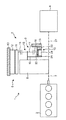
従来、車両用の発電装置として、図11に示すように、内燃機関101のクランク軸端102に設けられたプーリ103にVベルト104を介して接続されたオルタネータ105が知られている。
Conventionally, as a power generator for a vehicle, as shown in FIG. 11, an
また、オルタネータ105に駆動の機能を付加し、温間時(暖機後)の内燃機関始動を可能にした(特許文献1〜3のISG参照。)、更に車両走行時に駆動力の補助を行なう装置等が知られている。
In addition, a driving function is added to the
しかしながら、前記による内燃機関始動方法では、冷間時の始動が出来なくなる事がある。これは、冷間時では、内燃機関の潤滑油の温度が低下する事で潤滑油の粘度が上昇し、始動時の撹拌抵抗が大きくなるとともに、Vベルト104とプーリ103との間での摩擦係数が低下して、Vベルト104とプーリ103との間で滑りが発生し、オルタネータ105の回転駆動力が内燃機関101に伝達できない等が要因として挙げられている。
However, the internal combustion engine starting method according to the above may not be able to start when cold. This is because, when cold, the temperature of the lubricating oil in the internal combustion engine decreases, the viscosity of the lubricating oil increases, the stirring resistance at the time of starting increases, and the friction between the V-
このような問題から、前記のような装置を備えた車両においては、冷間時の内燃機関始動にも対応可能とする為に、オルタネータ105とは別に、スタータモータ106を必ず備えている。なお、図11において、107はリングギヤ、108はトルクコンバータなどの発進装置、109は変速機である。
Due to such a problem, a vehicle equipped with the above-described device always includes a
従って、本発明の目的は、前記問題を解決することにあって、Vベルトとプーリとを使うことなく、内燃機関と回転電機とを連結して冷間時の始動を確実に可能とする、回転電機付き動力伝達装置を提供することにある。 Accordingly, an object of the present invention is to solve the above-mentioned problem, and without using a V-belt and a pulley, the internal combustion engine and the rotating electric machine are connected to enable a start in the cold state. The object is to provide a power transmission device with a rotating electrical machine.
前記目的を達成するために、本発明は以下のように構成する。 In order to achieve the above object, the present invention is configured as follows.
本発明の1つの態様によれば、車両の内燃機関の出力軸から変速機までの動力伝達経路に配置された動力伝達装置において、
前記出力軸と同軸上に配置された回転電機と、
前記動力伝達装置と前記回転電機とに隣接して配置されて、前記動力伝達装置の外殻あるいはそれと同一回転する同一回転部材と、前記回転電機の回転子との間で、減速比の異なる少なくとも2つの動力伝達経路を機械的に切換え可能な変速装置とを備える、回転電機付き動力伝達装置を提供する。
According to one aspect of the present invention, in the power transmission device disposed in the power transmission path from the output shaft of the internal combustion engine of the vehicle to the transmission,
A rotating electrical machine disposed coaxially with the output shaft;
The power transmission device and the rotating electrical machine are arranged adjacent to each other, and the outer shell of the power transmission device or the same rotating member that rotates in the same manner and the rotor of the rotating electrical machine have different reduction ratios. Provided is a power transmission device with a rotating electrical machine that includes a transmission that can mechanically switch between two power transmission paths.
本発明の前記第1態様によれば、前記動力伝達装置と前記回転電機とに隣接して前記変速装置を配置して、前記動力伝達装置の外殻あるいはそれと同一回転する前記同一回転部材と、前記回転電機の前記回転子との間で、減速比の異なる少なくとも2つの動力伝達経路を機械的に切換え可能とすることにより、Vベルトとプーリとを使うことなく、冷間時でも、前記回転電機の回転駆動力を内燃機関に確実に伝達でき、冷間時に内燃機関を確実に始動させることができる。 According to the first aspect of the present invention, the transmission is disposed adjacent to the power transmission device and the rotating electrical machine, and the same rotating member that rotates in the same manner as the outer shell of the power transmission device, or By enabling mechanical switching of at least two power transmission paths having different reduction ratios with the rotor of the rotating electrical machine, the rotation can be performed even when cold without using a V-belt and a pulley. The rotational driving force of the electric machine can be reliably transmitted to the internal combustion engine, and the internal combustion engine can be reliably started when cold.
以下、図面を参照して本発明における第1実施形態を詳細に説明する。なお、各実施形態の説明において、同じ部品又は部分は同じ参照符号を付することにより、重複した説明を省略している。 Hereinafter, a first embodiment of the present invention will be described in detail with reference to the drawings. In the description of each embodiment, the same parts or portions are denoted by the same reference numerals, and redundant description is omitted.
<第1実施形態>
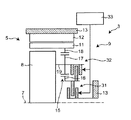
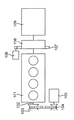
本発明の第1実施形態にかかる回転電機付き動力伝達装置は、図1に示すように、クラッチ又はトルクコンバータ等の動力伝達装置3に回転電機5を組合わせて、ISG(Integrated Starter Generator)及びスタータモータの持つ機能を統合し、コスト及びスペースのメリットを得るための構成である。このような構成において、複数の機能を実現する為に変速装置9を設けて、冷間時でも、回転電機5の回転駆動力を内燃機関、例えばエンジン2に確実に伝達でき、冷間時にエンジン2を確実に始動させることができるようにしている。
<First Embodiment>
As shown in FIG. 1, the power transmission device with a rotating electrical machine according to the first embodiment of the present invention combines an ISG (Integrated Starter Generator) and a
さらに、本発明の実施形態では、動力伝達装置3に回転電機5を組合せて配置するとき、1つの回転電機5でオルタネータ及びスタータモータの持つ発電機能及びエンジン始動機能の両方を発揮できるように統合し、コスト削減及びスペース削減を図るように構成している。
Furthermore, in the embodiment of the present invention, when the rotary
このような回転電機付き動力伝達装置3は、具体的には、図1に示すように、車両1のエンジン2の出力軸7から変速機4までの動力伝達経路に配置されている。
Specifically, such a
この動力伝達装置3は、少なくとも、出力軸7と同軸上に配置された回転電機5と、動力伝達装置3と回転電機5とに隣接して配置されて、動力伝達装置3の外殻あるいはそれと同一回転(一体的に回転)する同一回転部材8と、回転電機5の回転子11との間で、減速比の異なる少なくとも2つの動力伝達経路を機械的に切換え可能な変速装置9とを備えている。
The
以下、このような構成について、詳しく説明する。 Hereinafter, such a configuration will be described in detail.
回転電機5は、ケースなどの固定端13に固定された固定子12と、固定子12に対して回転する回転子11とで構成されている。回転子11の回転軸は、出力軸7と同軸である。
The rotating
動力伝達装置3の外殻8は、摩擦式クラッチの外殻(例えば、クラッチカバー)、トルクコンバータの外殻、又はフルードカップリングの外殻で構成することができる。外殻8と同一回転(一体的に回転)する同一回転部材8としては、エンジン2の出力軸と連結されて同期回転するトルクコンバータのドライブプレート、フルードカップリングの内燃機関側に連結されるドライブプレート、摩擦式クラッチの内燃機関側に連結されるフライホイール、又は電磁クラッチの内燃機関側に連結される部材であってもよい。
The
変速装置9は、一例として、エンジン2の出力軸7及び回転電機5と同軸上に配置した遊星歯車機構15と、遊星歯車機構15のサンギヤ16とピニオンキャリア19との間、あるいはサンギヤ16と固定端13との間の相対回転を規制又は開放可能な断接機構10とを備えている。
As an example, the
遊星歯車機構15は、サンギヤ16と、複数のピニオンギヤ17と、リングギヤ18と、ピニオンキャリア19とを備えている。
The
各ピニオンギヤ17は、リングギヤ18とサンギヤ16とにかみ合っている。
Each
リングギヤ18は、複数のピニオンギヤ17とかみ合っている。リングギヤ18は、回転子11と接続されて回転子11と一体的に回転する。
The
ピニオンキャリア19は、複数のピニオンギヤ17を回転自在に支持するとともに、動力伝達装置3の外殻あるいはそれと同一回転する同一回転部材(以下、動力伝達装置3の同一回転部材と略す。)8と接続されて一体的に回転する。
The
サンギヤ16は周囲に複数のピニオンギヤ17がかみ合っており、始動モードと発電モードとでサンギヤ16の回転が反転することを後述する断接機構10では利用して、経路の切り替えを自動的に行えるようにしている。
The
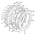
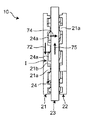
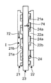
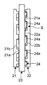
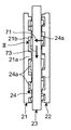
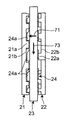
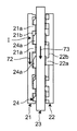
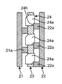
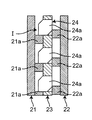
また、断接機構10は、図2〜図4に示すように、第1爪リング21と、第2爪リング22と、ハブリング23と、係合リング24とで構成されて、クラッチ機能とブレーキ機能とを発揮可能な機構である。
The connection /
ハブリング23の内側に係合リング24が挿入されて係合されて、第1爪リング21と第2爪リング22との間で、一体的に正逆回転可能に配置され、かつハブリング23に対して係合リング24が軸方向には摺動可能としている。
An
第1爪リング21は、出力軸7と同軸の断接機構10の回転軸27の軸方向の一端(例えばエンジン側)に配置され、かつ、ピニオンキャリア19に接続されて、ピニオンキャリア19とともに正逆回転する。第1爪リング21は、その一側部に、周方向沿いに等間隔に多数の第1突起21aを第1円環部21cから係合リング24側に向けて突出させ、隣接する第1突起21a間には第1凹部21bをそれぞれ有している。各第1突起21aは平面形状が、例えば矩形である。
The
第2爪リング22は、断接機構10の回転軸27の軸方向の他端(例えば変速機側)に配置されて固定端13に固定されている。第2爪リング22は、第1爪リング21と面対称な構造を有しており、その一側部に、周方向沿いに等間隔に多数の第2突起22aを第2円環部22cから係合リング24側に向けて突出させ、隣接する第2突起22a間には第2凹部22bをそれぞれ有している。各第2突起22aは平面形状が、例えば矩形である。
The
ハブリング23は、サンギヤ16に接続されて、サンギヤ16ととともに第1爪リング21と第2爪リング22との間で正逆回転する。ハブリング23は、周方向沿いに等間隔に多数の第3突起23aを第3円環部23cから径方向中心側に向けて突出させ、隣接する第3突起23a間には第3凹部23bをそれぞれ有している。各第3突起23aは平面形状が、例えば矩形である。
The
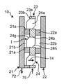
係合リング24は、ハブリング23の径方向の内側に配置され、ハブリング23と係合して一体的に正逆回転しかつ出力軸7の軸方向には進退移動可能でかつ第1突起21aと第2突起22aとに交互に係合可能な係合突起24aを有する。具体的には、係合リング24は、周方向沿いに等間隔に多数の係合突起24aを第4円環部24cから径方向外側に向けて突出させ、隣接する係合突起24a間には第4凹部24bをそれぞれ有している。各係合突起24aは平面形状が、例えば矩形であり、かつ1つの対角、例えば、左上の角と右下の角には、面取りなどにより第1傾斜面24g及び第2傾斜面24hが形成されている。各係合突起24aの軸方向の長さは係合リング24の軸方向の長さよりも長く、第1傾斜面24g又は第2傾斜面24hのいずれかが、必ず、係合リング24から軸方向に突出して、第1突起21a又は第2突起22aと係合可能な状態となっている。係合リング24の各係合突起24aはハブリング23の各第2凹部23b内に係合しかつ係合リング24の各第4凹部24bにはハブリング23の各第3突起23aが係合することにより、ハブリング23と係合リング24とは回転方向には係合して相対的な回転は不可で一体的に正逆回転する一方、軸方向には係合リング24がハブリング23に対して第1爪リング21側に突出する第1突出位置I(図3、図5A、及び図6A参照)と第2爪リング22側に突出する第2突出位置II(図4、図5F、及び図6F参照)との間で進退移動可能に係合している。 このような構成の断接機構10は、断接機構10の外観図としての図5A〜図5F及びハブリング23を破断除去した状態での図6A〜図6Fに示すように動作する。
The
係合突起24aの第1突出位置Iでは、図5A及び図6Aに示すように、第1爪リング21の第1突起21aの右下角部が第1傾斜面24gを摺動可能となっている。このとき、図5A〜図5B及び図6A〜図6Bに示すように、第1爪リング21の下向き矢印72の方向の回転と係合リング24の上向き矢印75の方向の回転とにより、第1突起21aの右下角部が第1傾斜面24gに接触して下向きに移動することにより、第1傾斜面24gを持つ係合突起24aを右向き(矢印74参照)に徐々に移動させる。これにより、第1突出位置Iから第2突出位置IIへの移動が開始される。
5A and 6A, the lower right corner of the
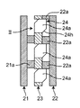
図5B及び図6Bの状態を経過したのち、図5C及び図6Cに示すように、第1突起21aの右下角部が第1傾斜面24gの下端縁まで移動し終えると、係合リング24は、第1突出位置Iから第2突出位置IIまで移動が完了したことになる。この第2突出位置IIでは、各係合突起24aの上面が、第2爪リング22の各第2凹部22b内に入り、各第2突起の下面に当接して、係合リング24と第2爪リング22とが係合されて相対的には回転不可となる。このとき、第2爪リング22は回転不可に固定端13に固定されているため、係合リング24も回転を停止し、ハブリング23及びサンギヤ16も回転を停止することになる。なお、第1爪リング21は自在に正逆回転可能となっている。
After the state of FIG. 5B and FIG. 6B has elapsed, as shown in FIG. 5C and FIG. 6C, when the lower right corner of the
一方、各係合突起24aが第2突出位置IIまで移動して係合リング24が回転を停止したのち、サンギヤ16及びハブリング23を介して係合リング24が先とは逆回転、すなわち、図5D及び図6Dにおいて上方向ではなく下方向(矢印73参照)に逆回転させられると、各係合突起24aが第2爪リング22の各第2突起22aの下面から離れて各第2凹部22b内を周方向に少し移動する。この逆回転は、始動モードと発電モードとでエンジン2と回転電機5の駆動及び被駆動の関係が逆転し、サンギヤ16の反力方向が反転することを意味している。
On the other hand, after each
その後、図5E及び図6Eに示すように、係合リング24の下向き矢印73の方向の回転により、各第2突起22aの左上の角部が各係合突起24aの第2傾斜面24hに上向きに移動することにより、第2傾斜面24hを持つ係合突起24aを左向き(矢印71参照)に徐々に移動させる。これにより、第2突出位置IIから第1突出位置Iへの移動が開始される。
Thereafter, as shown in FIGS. 5E and 6E, the rotation of the
その後、図5E及び図6Eの状態を経過したのち、図5F及び図6Fに示すように、第2突起22aの左上角部が第2傾斜面24hの上端縁まで移動し終えると、係合リング24は第2突出位置IIから第1突出位置Iまで移動が完了したことになる。この第1突出位置Iでは、各係合突起24aの下面が、第1爪リング21の各第1凹部21b内に入り、各第1突起21aの上面に当接して、係合リング24と第1爪リング21とが係合されて相対的には回転不可となる。よって、係合リング24と第1爪リング21とが一体的に下向きに(矢印73,72参照)回転することになる。
Thereafter, after the state of FIGS. 5E and 6E has elapsed, as shown in FIGS. 5F and 6F, when the upper left corner of the
ここで、断接機構10における「断」及び「接」の意味は、絶対的なものではなく、相対的な状態を意味している。すなわち、係合リング24(ハブリング23も同様)と第1爪リング21との間の断接と、係合リング24(ハブリング23も同様)と第2爪リング22との間の断接とにおいて、2つのリングが相対的に同期している状態を「接」と表現し、2つのリングが相対的に同期していない状態(すなわち、回転差を持つ状態、言い換えれば、相対回転可能な状態)を「断」と表現する。係合リング24と第1爪リング21との間の断接と、係合リング24と第2爪リング22との間の断接とは互いに連携して、常に両者が互いに異なる断接状態となるようにしている。
Here, the meanings of “disconnection” and “contact” in the connection /
具体的には、図5A〜図5C及び図6A〜図6Cに示すように、係合リング24の軸方向の第2爪リング22側(図5A〜図5C及び図6A〜図6Cでは右方向)への移動(矢印74参照)により、係合リング24の係合突起24aが第1突出位置Iから回転軸27の軸方向沿いに移動して第2突出位置IIに位置するとき、係合リング24と第2爪リング22との間は「接」となると同時に、係合リング24と第1爪リング21との間は「断」となる。よって、互いに「接」である係合リング24と第2爪リング22とは回転停止となるが、互いに「断」である係合リング24と第1爪リング21とにおいては、回転停止の係合リング24に対して第1爪リング21は正逆可能となる。
Specifically, as shown in FIGS. 5A to 5C and FIGS. 6A to 6C, the
一方、図5D〜図5F及び図6D〜図6Fに示すように、係合リング24の軸方向の第1爪リング21側(図5D〜図5F及び図6D〜図6Fでは左方向)への移動(矢印71参照)により、係合リング24の係合突起24aが第2突出位置IIから回転軸27の軸方向沿いに移動して第1突出位置Iに位置するとき、係合リング24と第1爪リング21との間は「接」となると同時に、係合リング24と第2爪リング22との間は「断」となる。よって、互いに「接」である係合リング24と第1爪リング21とは同一方向に矢印72,73で示すように下向きに一体的に回転するが、互いに「断」である係合リング24と第2爪リング22とにおいては、固定された第2爪リング22とは無関係に係合リング24は回転可能となる。
On the other hand, as shown in FIG. 5D to FIG. 5F and FIG. 6D to FIG. 6F, the
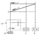
図7は、回転電機付き動力伝達装置の作動状態の共線図であり、各回転要素の回転速度とトルクとの力学的な関係を示している。図7の共線図は、横軸X方向において、3本の縦線は、回転要素として、左から、遊星歯車機構15のサンギヤ16と、ピニオンキャリア19と、リングギヤ18とのギヤ比の関係を示し、縦軸Y方向において相対的回転速度を示す二次元座標であり、実線と点線が始動モードと発電モードのそれぞれの回転速度すなわち出力軸に接続されるエンジン2と回転電機5とのそれぞれの回転速度を示している。
FIG. 7 is an alignment chart of the operating state of the power transmission device with a rotating electrical machine, and shows a dynamic relationship between the rotational speed and torque of each rotating element. In the collinear diagram of FIG. 7, in the horizontal axis X direction, the three vertical lines indicate the relationship between the gear ratios of the
始動モードでは、サンギヤ16は回転速度がゼロで停止しており、リングギヤ18からピニオンキャリア19へは減速して回転伝達している。
In the start mode, the
発電モードでは、サンギヤ16とピニオンキャリア19とリングギヤ18とが一体的に回転し、減速比=1となっている。
In the power generation mode, the
この図7の、サンギヤ16と固定端13との間のブレーキ要素BRと、サンギヤ16とピニオンキャリア19との間のクラッチ要素CLは、断接機構10で達成している。このブレーキ要素BRとクラッチ要素CLによる断接機構10により、一つの回転電機5で両極端な要求特性を満足する事が可能になる。
The brake element BR between the
すなわち、この第1実施形態の構成においては、図7に示すように、高トルク及び低回転速度の特性が要求されるエンジン始動モードでは、回転電機5が発生するトルク及び回転速度を遊星歯車機構15で減速してエンジン2に伝達して、良好な始動特性を得る必要がある。このため、回転電機5の回転子11の回転は、遊星歯車機構15のリングギヤ18とピニオンギヤ17とピニオンキャリア19とを介して、動力伝達装置3の外殻あるいはそれと同一回転する部材8に伝達される。このとき、断接機構10では、ピニオンギヤ17の回転に伴いサンギヤ16も当初は回転を開始して、第1爪リング21が図5A及び図6Aに示す下向き方向(矢印72参照)の回転と同時に係合リング24も図5A及び図6Aに示す上向き方向(矢印75参照)の回転を開始する。すると、係合突起24aが右方向(矢印74参照)に移動して第1係合突起21aとの係合を解除して第2係合突起22aと係合すると、係合リング24とともにサンギヤ16の回転が停止させられる。この結果、サンギヤ16が固定された状態でピニオンギヤ17の回転に伴いピニオンキャリア19が回転し続ける。このピニオンキャリア19の回転がエンジン2に伝達されることにより、回転電機5の回転子11の回転が遊星歯車機構15で減速して伝達されることになる。
That is, in the configuration of the first embodiment, as shown in FIG. 7, in the engine start mode in which characteristics of high torque and low rotational speed are required, the torque and rotational speed generated by the rotating
これが、断接機構10により、サンギヤ16とピニオンキャリア19との間が開放されかつサンギヤ16と固定端13との間の相対回転を規制した状態で、リングギヤ18から、ピニオンギヤ17を介してピニオンキャリア19に至る動力伝達経路のうちの第1経路である。
In this state, the connection /
一方、エンジン2の始動が完了した後、低トルク及び高回転速度の特性が要求される発電モードに移行すると、遊星歯車機構15の構成要素間の相対回転を断接機構10で規制する事で、エンジン2が発生するトルク及び回転速度は、直結状態(減速比=1)で回転電機5に伝達するようにしている。このため、エンジン2の出力軸7からの回転は、動力伝達装置3の外殻あるいはそれと同一回転する部材8から遊星歯車機構15のピニオンキャリア19とピニオンギヤ17とリングギヤ18とを介して、回転電機5の回転子11に伝達される。このとき、断接機構10では、ピニオンキャリア19の回転に伴いピニオンギヤ17とサンギヤ16とも一体的に回転して、係合リング24が図5D及び図6Dに示す下向き方向(矢印73参照)の回転を開始し、係合突起24aが左方向(矢印71参照)に移動して第2係合突起22aとの係合を解除して第1係合突起21aと係合すると、係合リング24と第1爪リング21とが一体的に回転する。
On the other hand, after the start of the
これが、断接機構10により、サンギヤ16とピニオンキャリア19との間が規制されかつサンギヤ16と固定端13との間の相対回転を開放した状態で、ピニオンキャリア19からピニオンギヤ17を介してリングギヤ18に至る動力伝達経路の第2経路である。
This is because the connection /
このように前記第1実施形態によれば、動力伝達装置3と回転電機5とに隣接して変速装置9を配置して、動力伝達装置3の外殻あるいはそれと同一回転する同一回転部材8と、回転電機5の回転子11との間で、減速比の異なる少なくとも2つの動力伝達経路を機械的に切換え可能とすることにより、Vベルトとプーリとを使うことなく、エンジン2と回転電機5とを連結して冷間時の始動が確実に可能となる。また、動力伝達経路の切替の為に、外部から操作する機構又は信号を持つ必要がなく、駆動及び被駆動の関係がエンジン始動モードと発電モードとにおいて逆転する事を利用したシステムであり、他の構成も簡素な構成で断接機構10を実現する事が出来る。また、従来の構成と比較して、オルタネータとスタータモータとの機能を第1実施形態の構成に統合することで、スタータモータ、リングギヤ、Vベルト、及びプーリなどの部品を廃止することが出来て、コスト低減が図れる。また、前記した統合は、変速装置9を備える事で、低回転速度及び高トルクと、高回転速度及び低トルクとの背反する2つの特性を1つの回転電機5で達成することが可能となり、かつ低温条件下でもスリップが発生しない歯車伝達とする事により実現可能となり、部品の廃止により、該部品が占有していたスペースが不要になり、小型軽量化が図れる。また、通常、遊星歯車機構15は潤滑油雰囲気下で使用されるケースが多いのに対して、第1実施形態においては、車両稼働中の大部分の時間は発電モードで使用し、始動モードを使用する時間はごく短時間であるため、潤滑油雰囲気下でなくとも実現可能となる。すなわち、発電モードでは、遊星歯車機構15の構成要素が一体回転する、すなわち、歯車間の転動が無い状態となるため、潤滑油雰囲気下でなくとも実現可能となっている。このような特徴により、シール及び潤滑構造等の簡略化が可能になり、スペース及びコスト面での優れたものとなる。
Thus, according to the first embodiment, the
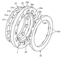
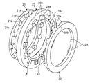
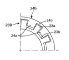
<変形例>
なお、本発明は前記実施形態に限定されるものではなく、その他種々の態様で実施できる。例えば、図8に示す変形例として、ハブリング23Bと係合リング24Bとの内外方向の配置を互いに入れ替えることもできる。この例では、係合突起24aと第3凹部23bとの係合関係、及び、第3突起23aと第4凹部24bとの係合関係が径方向の内外で逆転しているだけであり、動作は、第1実施形態と全く同一である。
<Modification>
In addition, this invention is not limited to the said embodiment, It can implement in another various aspect. For example, as a modification shown in FIG. 8, the inner and outer arrangements of the
<第2実施形態>
また、断接機構10は、第1実施形態の機構に限られず、他の構成で構成することもできる。
Second Embodiment
Moreover, the connection /
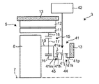
例えば、本発明の第2実施形態として、前記断接機構10は、摩擦式ブレーキ31と、摩擦式クラッチ32と、それらの制御機構33とで構成することもできる。
For example, as a second embodiment of the present invention, the connecting /
制御機構33は、例えば、エンジン始動のタイミング信号を信号回路などから出力させて、その信号を基に、摩擦式ブレーキ31と摩擦式クラッチ32とを独立して別々に駆動可能な油圧式ピストン又は各種アクチュエータ等で構成するようにしてもよい。
For example, the
摩擦式のブレーキ31は、サンギヤ16と固定端13との間に配置されている。摩擦式のブレーキ31をかけてサンギヤ16と固定端13とを一体的にしてサンギヤ16の回転を停止させる一方、摩擦式のブレーキ31を解放して、固定端13に対してサンギヤ16を自在に正逆回転可能とする。例えば、摩擦式ブレーキ31の場合には、交互に重なり合ったディスクとドリブンプレートとを軸方向に押し付けていくことで回転を停止させるものであって、押し付ける動作自体は、油圧ピストンで直押し、又は、ベアリングを介して電動アクチュエータで押す動作で行うことができる。
The
摩擦式のクラッチ32は、サンギヤ16とピニオンキャリア19との間に配置されている。摩擦式のクラッチ32は、サンギヤ16とピニオンキャリア19と接続してサンギヤ16とピニオンキャリア19とを一体的に回転させたり、サンギヤ16とピニオンキャリア19との接続を解除して、サンギヤ16とピニオンキャリア19とが別々に回転するようにする。例えば、摩擦式クラッチ32の場合には、交互に重なり合ったディスクとドリブンプレートとを軸方向に押し付けていくことでトルク伝達をするものであって、押し付ける動作自体は、油圧ピストンで直押し、又は、ベアリングを介して電動アクチュエータで押す動作で行うことができる。
The
制御機構33は、これらのブレーキ31及びクラッチ32の断接を操作する為に、信号回路などから信号を基に油圧式ピストン又は電動アクチュエータなどの各種アクチュエータ等を駆動制御する。
The
このような構成でも、第1実施形態の作用効果を奏することができる。 Even with such a configuration, the effects of the first embodiment can be achieved.
<第3実施形態>
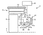
また、他の構成の断接機構として、図10A〜図10Cに示す本発明の第3実施形態では、ドグ式あるいはシンクロ式クラッチ41と、その制御機構42とで構成することもできる。
<Third Embodiment>
Further, as a connecting / disconnecting mechanism of another configuration, in the third embodiment of the present invention shown in FIGS. 10A to 10C, it can be configured by a dog type or synchro clutch 41 and its
制御機構42は、例えば、エンジン始動のタイミング信号を信号回路などから出力させて、その信号を基に、ドグ式あるいはシンクロ式クラッチ41のブレーキ・クラッチ要素を駆動可能な油圧式ピストン又は各種アクチュエータ等で構成するようにしてもよい。
The
サンギヤ16と固定端13との間にドグあるいはシンクロメッシュ方式(ドグ式あるいはシンクロ式)のブレーキ要素44を設け、サンギヤ16とピニオンキャリア19との間にドグあるいはシンクロメッシュ方式(ドグ式あるいはシンクロ式)のクラッチ要素45を設けている。
A dog or synchromesh type (dog type or synchro type)
また、これらのブレーキ要素44及びクラッチ要素45の断接を操作する為に、制御機構42を備えている。
In addition, a
図10Aは、サンギヤ16とピニオンキャリア19とが同期(=「接」)している状態で、図10Bは、サンギヤ16と固定端13とが同期している状態である。図10A及び図10Bで横方向にスライドしている部品がスリーブ41aになる。
10A shows a state in which the
ここで、シンクロ機構は、同期させる部材同士の相対回転差を、ある程度吸収して断接する事が可能である。一方、ドグクラッチは、同期させる部材同士の相対回転差をほぼゼロにしてから断接する。細かい機能及び機構は、両者で異なるが、本質的に、摩擦クラッチのような動力伝達形態を取らず、歯と歯とで噛合う伝達形態であるという点では同じであるため、ここでは、ドグクラッチあるいはシンクロ機構としてまとめて説明する。 Here, the synchro mechanism can absorb the relative rotation difference between the members to be synchronized to some extent and can connect and disconnect. On the other hand, the dog clutch is connected / disconnected after the relative rotational difference between the synchronized members is substantially zero. Although the detailed functions and mechanisms differ between the two, the dog clutch is essentially the same in that it does not take a power transmission form like a friction clutch, but is a transmission form that meshes between teeth. Or it demonstrates collectively as a synchro mechanism.
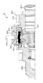
また、シンクロ機構の実体形状の一例を図10Cに示す。 An example of the actual shape of the synchro mechanism is shown in FIG. 10C.
シフト・フォークなどの操作部材41bによって、スリーブ41aを図10A及び図10Cの右側に移動を開始させると、スリーブ41aと一体にシンクロナイザ・キー41cが移動し、その端面がシンクロナイザ・リング41dをギヤ41eのコーン部41fに押し付け、この摩擦力でギヤ41eの回転がスリーブ41aの回転速度に近づく。さらにスリーブ41aを移動させると、スリーブ41aとシンクロナイザ・キー41cの突起部41gのかみ合いが外れ、スリーブ41aのスプライン41hがシンクロナイザ・リング41dのスプライン41jを通過してギヤ41eのスプライン41kとかみ合う。
When the
すなわち、シフト・フォークなどの操作部材41bの初期段階では、スリーブ41aとシンクロナイザ・キー41cの突起部41gとの状態は、かみ合っており、スリーブ41aとシンクロナイザ・リング41dのスプライン41jの状態は、食い違った状態である。このとき、摩擦は、シンクロナイザ・キー41cの端面でシンクロナイザ・リング41dをギヤ41eのコーン(円錐)部41fに押し付けることにより発生し、同期作用が始まる。
That is, in the initial stage of the
シフト・フォークなどの操作部材41bの中期段階では、スリーブ41aとシンクロナイザ・キー41cの突起部41gとの状態は、かみ合いが外れており、スリーブ41aとシンクロナイザ・リング41dとのスプライン41jの状態は、先端部同士が当った状態であり、摩擦は、スリーブ41aに押されて、シンクロナイザ・リング41dは、ギヤ41eのコーン部41fを強く圧着することにより発生して、同期作用は強まっている。すなわち、このような強い圧着動作が、断接機構での「接」を意味し、これらの動作とは逆の解除動作が「断」を意味する。
In the middle stage of the
なお、41mはピニオンキャリア19に接続されるメインシャフト、41pは固定端13に固定されるクラッチシャフトである。
In addition, 41m is a main shaft connected to the
このような構成でも、第1実施形態の作用効果を奏することができる。 Even with such a configuration, the effects of the first embodiment can be achieved.
なお、前記様々な実施形態又は変形例のうちの任意の実施形態又は変形例を適宜組み合わせることにより、それぞれの有する効果を奏するようにすることができる。また、実施形態同士の組み合わせ又は実施例同士の組み合わせ又は実施形態と実施例との組み合わせが可能であると共に、異なる実施形態又は実施例の中の特徴同士の組み合わせも可能である。 In addition, it can be made to show the effect which each has by combining arbitrary embodiment or modification of the said various embodiment or modification suitably. In addition, combinations of the embodiments, combinations of the examples, or combinations of the embodiments and examples are possible, and combinations of features in different embodiments or examples are also possible.
本発明の前記態様にかかる回転電機付き動力伝達装置は、設計自由度が大きくなり、出力性能を向上させることができて、車両のオルタネータ及びスタータモータの持つ発電機能及びエンジン始動機能を統合する回転電機付き動力伝達装置等として有用である。 The power transmission device with a rotating electrical machine according to the above aspect of the present invention has a greater degree of design freedom, can improve output performance, and integrates the power generation function and engine start function of the alternator and starter motor of the vehicle. It is useful as a power transmission device with an electric machine.
1 車両
2 エンジン
3 動力伝達装置
4 変速機
5 回転電機
7 出力軸
8 動力伝達装置の外殻あるいはそれと同一回転する部材
9 変速装置
10 断接機構
11 回転子
12 固定子
13 固定端
15 遊星歯車機構
16 サンギヤ
17 ピニオンギヤ
18 リングギヤ
19 ピニオンキャリア
21 第1爪リング
21a 第1突起
21b 第1凹部
21c 第1円環部
22 第2爪リング
22a 第2突起
22b 第2凹部
22c 第2円環部
23,23B ハブリング
23a 第3突起
23b 第3凹部
23c 第3円環部
24,24B 係合リング
24a 係合突起
24b 第4凹部
24c 第4円環部
27 断接機構の回転軸
31 摩擦式ブレーキ
32 摩擦式クラッチ
33 制御機構
41 ドグ式あるいはシンクロ式クラッチ
41a スリーブ
41b 操作部材
41c シンクロナイザ・キー
41d シンクロナイザ・リング
41e ギヤ
41f コーン部
41g 突起部
41h スプライン
41j スプライン
41k スプライン
41m メインシャフト
41p クラッチシャフト
42 制御機構
44 ドグあるいはシンクロメッシュ方式のブレーキ要素
45 ドグあるいはシンクロメッシュ方式のクラッチ要素
71 左向き矢印の移動
72,73 下向き矢印の回転
74 右向き矢印の移動
75 上向き矢印の回転
I 第1突出位置
II 第2突出位置
BR ブレーキ要素
CL クラッチ要素
DESCRIPTION OF SYMBOLS 1
Claims (9)
前記出力軸と同軸上に配置された回転電機と、
前記動力伝達装置と前記回転電機とに隣接して配置されて、前記動力伝達装置の外殻あるいはそれと同一回転する同一回転部材と、前記回転電機の回転子との間で、減速比の異なる少なくとも2つの動力伝達経路を機械的に切換え可能な変速装置とを備える、回転電機付き動力伝達装置。 In the power transmission device arranged in the power transmission path from the output shaft of the internal combustion engine of the vehicle to the transmission,
A rotating electrical machine disposed coaxially with the output shaft;
The power transmission device and the rotating electrical machine are arranged adjacent to each other, and the outer shell of the power transmission device or the same rotating member that rotates in the same manner and the rotor of the rotating electrical machine have different reduction ratios. A power transmission device with a rotating electrical machine, comprising: a transmission capable of mechanically switching between two power transmission paths.
前記内燃機関の前記出力軸及び前記回転電機と同軸上に配置した遊星歯車機構と、
前記遊星歯車機構に接続される断接機構とを備え、
前記遊星歯車機構は、
サンギヤと、
前記サンギヤとかみ合うピニオンギヤと、
前記ピニオンギヤを回転自在に支持するとともに前記動力伝達装置の前記外殻あるいはそれと同一回転する前記同一回転部材と接続されるピニオンキャリアと、
前記回転電機の前記回転子と接続されて一体的に回転するとともに、前記ピニオンギヤとかみ合うリングギヤと、
前記動力伝達装置の前記外殻あるいはそれと同一回転する前記同一回転部材と接続されて一体的に回転するとともに、前記ピニオンギヤを回転自在に支持するピニオンキャリアとを備え、
前記断接機構は、前記遊星歯車機構の前記サンギヤと前記ピニオンキャリアとの間、あるいは前記サンギヤと固定端との間の相対回転を規制又は開放可能であり、
前記2つの動力伝達経路は、
前記断接機構により、前記サンギヤと前記ピニオンキャリアとの間が開放されかつ前記サンギヤと固定端との間の相対回転を規制した状態で、前記回転子とともに回転する前記リングギヤから、前記ピニオンギヤを介して、前記動力伝達装置の前記外殻あるいはそれと同一回転する前記同一回転部材に接続された前記ピニオンキャリアに至る第1経路と、
前記断接機構により、前記サンギヤと前記ピニオンキャリアとの間が規制されかつ前記サンギヤと固定端との間の相対回転を開放した状態で、前記動力伝達装置の前記外殻あるいはそれと同一回転する前記同一回転部材に接続された前記ピニオンキャリアから、前記ピニオンギヤを介して、前記回転子とともに回転する前記リングギヤに至る第2経路とである、請求項1に記載の回転電機付き動力伝達装置。 The transmission is
A planetary gear mechanism arranged coaxially with the output shaft of the internal combustion engine and the rotating electrical machine;
A connection / disconnection mechanism connected to the planetary gear mechanism,
The planetary gear mechanism is
With sun gear,
A pinion gear meshing with the sun gear;
A pinion carrier that rotatably supports the pinion gear and is connected to the outer shell of the power transmission device or the same rotating member that rotates the same as the outer shell;
A ring gear connected to the rotor of the rotating electrical machine and rotating integrally, and meshing with the pinion gear;
A pinion carrier that is connected to the outer shell of the power transmission device or the same rotating member that rotates in the same manner and rotates integrally therewith, and rotatably supports the pinion gear;
The connecting / disconnecting mechanism is capable of regulating or releasing relative rotation between the sun gear and the pinion carrier of the planetary gear mechanism or between the sun gear and a fixed end.
The two power transmission paths are:
The ring gear that rotates together with the rotor from the ring gear via the pinion gear in a state in which the connection between the sun gear and the pinion carrier is opened by the connection / disconnection mechanism and the relative rotation between the sun gear and the fixed end is restricted. A first path leading to the pinion carrier connected to the outer shell of the power transmission device or the same rotating member that rotates in the same manner;
The outer gear of the power transmission device or the same rotating as the outer shell of the power transmission device in a state where the connection between the sun gear and the pinion carrier is restricted by the connection / disconnection mechanism and the relative rotation between the sun gear and the fixed end is released. 2. The power transmission device with a rotating electrical machine according to claim 1, wherein the second transmission path is a second path from the pinion carrier connected to the same rotating member to the ring gear rotating together with the rotor via the pinion gear.
前記ピニオンキャリアに接続されて、前記ピニオンキャリアとともに回転しかつ第1突起を有する第1爪リングと、
前記固定端に固定され、かつ第2突起を有する第2爪リングと、
前記サンギヤに接続されて、前記サンギヤとともに、前記第1爪リングと第2爪リングとの間で回転するハブリングと、
前記ハブリングの径方向の内側又は外側に配置され、前記ハブリングと係合して一体的に正逆回転しかつ回転軸の軸方向には進退移動可能で、前記第1突起と前記第2突起とのうちいずれか一方と係合されかついずれか他方と係合解除される係合突起を有する係合リングとを備え、
前記第1爪リングが第1方向へ回転するとともに前記係合リングが前記第1方向とは逆の第2方向に回転することにより、前記係合リングの前記係合突起と前記第1爪リングの前記第1突起との係合が解除されて前記第1爪リングは前記係合リングとは無関係に正逆回転可能となり、かつ、前記係合リングの前記係合突起と前記第2爪リングの前記第2突起とが係合して前記係合リングの回転が停止させられることにより、前記動力伝達経路は前記第1経路に切り替わる一方、
前記係合リングが前記第1方向に回転することにより、前記係合リングの前記係合突起と前記第2爪リングの前記第2突起との係合が解除されて前記係合リングが正逆回転可能となり、かつ前記係合リングの前記係合突起と前記第1爪リングの前記第1突起とが係合して前記係合リングと前記第1爪リングとが一体的に回転することにより、前記動力伝達経路は前記第2経路に切り替わる、請求項2に記載の回転電機付き動力伝達装置。 The connection / disconnection mechanism is:
A first claw ring connected to the pinion carrier, rotating with the pinion carrier and having a first protrusion;
A second claw ring fixed to the fixed end and having a second protrusion;
A hub ring connected to the sun gear and rotating with the sun gear between the first claw ring and the second claw ring;
It is arranged inside or outside in the radial direction of the hub ring, engages with the hub ring, rotates integrally forward and backward, and can move forward and backward in the axial direction of the rotation shaft. The first protrusion and the second protrusion An engagement ring having an engagement protrusion that is engaged with any one of them and disengaged with any other,
When the first claw ring rotates in the first direction and the engagement ring rotates in a second direction opposite to the first direction, the engagement protrusion of the engagement ring and the first claw ring When the engagement with the first protrusion is released, the first claw ring can rotate forward and backward independently of the engagement ring, and the engagement protrusion of the engagement ring and the second claw ring While the second projection of the engagement is engaged and the rotation of the engagement ring is stopped, the power transmission path is switched to the first path,
When the engagement ring rotates in the first direction, the engagement between the engagement protrusion of the engagement ring and the second protrusion of the second claw ring is released, and the engagement ring is forward and reverse. When the engagement projection of the engagement ring and the first projection of the first claw ring are engaged with each other, the engagement ring and the first claw ring rotate integrally. The power transmission device with a rotating electrical machine according to claim 2, wherein the power transmission path is switched to the second path.
前記サンギヤと前記固定端との間に配置された摩擦式ブレーキと、
前記サンギヤと前記ピニオンキャリアとの間に配置された摩擦式クラッチと、
前記摩擦式のブレーキと前記摩擦式クラッチとをそれぞれ独立して動作制御する制御機構とを備える、請求項2に記載の回転電機付き動力伝達装置。 The connection / disconnection mechanism is:
A friction brake disposed between the sun gear and the fixed end;
A friction clutch disposed between the sun gear and the pinion carrier;
The power transmission device with a rotating electrical machine according to claim 2, further comprising a control mechanism for independently controlling the operation of the friction brake and the friction clutch.
前記サンギヤと前記固定端との間に配置されたドグ式あるいはシンクロ式ブレーキ要素と、
前記サンギヤと前記ピニオンキャリアとの間に配置されたドグ式あるいはシンクロ式クラッチ要素と、
前記ブレーキ要素と前記クラッチ要素とをそれぞれ独立して動作制御する制御機構とを備える、請求項2に記載の回転電機付き動力伝達装置。 The connection / disconnection mechanism is:
A dog-type or synchro-type brake element disposed between the sun gear and the fixed end;
A dog or synchro clutch element disposed between the sun gear and the pinion carrier;
The power transmission device with a rotating electrical machine according to claim 2, comprising a control mechanism for independently controlling the operation of the brake element and the clutch element.
Priority Applications (5)
| Application Number | Priority Date | Filing Date | Title |
|---|---|---|---|
| JP2017014996A JP6811630B2 (en) | 2017-01-31 | 2017-01-31 | Power transmission device with rotary electric machine |
| CN201880009010.8A CN110234866A (en) | 2017-01-31 | 2018-01-30 | Power transmission with rotating electric machine |
| US16/480,632 US20190351751A1 (en) | 2017-01-31 | 2018-01-30 | Power transmitting device with dynamo- electric machine |
| PCT/JP2018/002898 WO2018143172A1 (en) | 2017-01-31 | 2018-01-30 | Power transmitting device with dynamo-electric machine |
| EP18748389.6A EP3561291A1 (en) | 2017-01-31 | 2018-01-30 | Power transmitting device with dynamo-electric machine |
Applications Claiming Priority (1)
| Application Number | Priority Date | Filing Date | Title |
|---|---|---|---|
| JP2017014996A JP6811630B2 (en) | 2017-01-31 | 2017-01-31 | Power transmission device with rotary electric machine |
Publications (3)
| Publication Number | Publication Date |
|---|---|
| JP2018123722A true JP2018123722A (en) | 2018-08-09 |
| JP2018123722A5 JP2018123722A5 (en) | 2020-02-13 |
| JP6811630B2 JP6811630B2 (en) | 2021-01-13 |
Family
ID=63039590
Family Applications (1)
| Application Number | Title | Priority Date | Filing Date |
|---|---|---|---|
| JP2017014996A Active JP6811630B2 (en) | 2017-01-31 | 2017-01-31 | Power transmission device with rotary electric machine |
Country Status (5)
| Country | Link |
|---|---|
| US (1) | US20190351751A1 (en) |
| EP (1) | EP3561291A1 (en) |
| JP (1) | JP6811630B2 (en) |
| CN (1) | CN110234866A (en) |
| WO (1) | WO2018143172A1 (en) |
Families Citing this family (29)
| Publication number | Priority date | Publication date | Assignee | Title |
|---|---|---|---|---|
| EP3539869B1 (en) * | 2018-03-12 | 2020-09-23 | Ningbo Geely Automobile Research & Development Co. Ltd. | Clutch arrangement for a roadable aircraft |
| US10920730B2 (en) | 2019-04-16 | 2021-02-16 | Deere & Company | Multi-mode integrated starter-generator device with dog clutch arrangement |
| US10975938B2 (en) | 2019-04-16 | 2021-04-13 | Deere & Company | Multi-mode integrated starter-generator device with electromagnetic actuation assembly |
| US10920733B2 (en) | 2019-04-16 | 2021-02-16 | Deere & Company | Multi-mode integrated starter-generator device with preloaded clutch |
| US11156270B2 (en) | 2019-04-16 | 2021-10-26 | Deere & Company | Multi-mode integrated starter-generator device with transmission assembly mounting arrangement |
| US10968985B2 (en) | 2019-04-16 | 2021-04-06 | Deere & Company | Bi-directional integrated starter-generator device |
| US10975937B2 (en) * | 2019-04-16 | 2021-04-13 | Deere & Company | Multi-mode integrated starter-generator device with cam arrangement |
| US10821820B1 (en) | 2019-04-16 | 2020-11-03 | Deere & Company | Multi-mode starter-generator device transmission with single valve control |
| US10948054B2 (en) | 2019-04-16 | 2021-03-16 | Deere & Company | Multi-mode integrated starter-generator device with solenoid cam actuation apparatus |
| US11060496B2 (en) | 2019-04-16 | 2021-07-13 | Deere & Company | Multi-mode integrated starter-generator device |
| US10933731B2 (en) | 2019-04-16 | 2021-03-02 | Deere & Company | Multi-mode integrated starter-generator device with magnetic cam assembly |
| KR102791480B1 (en) | 2019-12-11 | 2025-04-03 | 현대자동차 주식회사 | Power transmission system of hybrid electric vehicle |
| US10900454B1 (en) | 2020-04-03 | 2021-01-26 | Deere & Company | Integrated starter-generator device with unidirectional clutch actuation utilizing a biased lever assembly |
| US11415199B2 (en) | 2020-05-29 | 2022-08-16 | Deere & Company | Bi-directional multi-speed drive |
| US11193560B1 (en) | 2020-05-29 | 2021-12-07 | Deere & Company | Work vehicle multi-speed drive assembly with bifurcated clutches |
| US12043981B2 (en) | 2020-09-25 | 2024-07-23 | Deere & Company | Work vehicle drive with multiple electric machines and torque combining assembly |
| US11326570B1 (en) | 2020-10-26 | 2022-05-10 | Deere & Company | Multi-mode integrated starter-generator device with unidirectional input |
| US11866910B2 (en) * | 2021-02-25 | 2024-01-09 | Deere & Company | Work vehicle multi-speed drive assembly with output control clutch |
| US11624170B2 (en) | 2021-02-25 | 2023-04-11 | Deere & Company | Work vehicle multi-speed drive assembly with clutch retention mechanism |
| US11719209B2 (en) | 2021-03-29 | 2023-08-08 | Deere & Company | Integrated starter-generator device with unidirectional clutch actuation utilizing biased lever assembly |
| DE102021109199A1 (en) * | 2021-04-13 | 2022-10-13 | Bayerische Motoren Werke Aktiengesellschaft | Motor vehicle with a linkage and linkage for a motor vehicle |
| US11761515B2 (en) * | 2021-05-20 | 2023-09-19 | Deere & Company | Work vehicle multi-speed drive assembly with guided dog clutch |
| US11686374B2 (en) | 2021-07-23 | 2023-06-27 | Deere & Company | Work vehicle multi-speed drive assembly providing multiple gear ratios at same step ratio |
| JP7642476B2 (en) * | 2021-07-28 | 2025-03-10 | 株式会社クボタ | Hybrid Power Transmission Mechanism |
| US11598384B2 (en) * | 2021-08-03 | 2023-03-07 | Hamilton Sundstrand Corporation | System and method to disconnect and brake a rotating device |
| DE102021132955B4 (en) | 2021-12-14 | 2023-06-29 | McLaren Engineering Crimmitschau Tech Center GmbH | Switchable clutch unit |
| US12092164B2 (en) * | 2022-03-22 | 2024-09-17 | Dana Heavy Vehicle Systems Group, Llc | Methods and systems for an asymmetric clutch collar |
| DE102022121626B3 (en) * | 2022-08-26 | 2024-02-15 | Schaeffler Technologies AG & Co. KG | Braking device for a drive arrangement of a vehicle and a vehicle with the drive arrangement |
| DE102023121849A1 (en) | 2023-08-16 | 2025-02-20 | Iav Gmbh Ingenieurgesellschaft Auto Und Verkehr | drive module for a motor vehicle |
Family Cites Families (15)
| Publication number | Priority date | Publication date | Assignee | Title |
|---|---|---|---|---|
| FR2806223B1 (en) | 2000-03-10 | 2003-10-03 | Valeo Equip Electr Moteur | POLYPHASE ROTATING ELECTRIC MACHINE |
| JP2003028034A (en) * | 2001-07-16 | 2003-01-29 | Hitachi Unisia Automotive Ltd | Starting generator |
| US7131933B2 (en) * | 2001-12-07 | 2006-11-07 | Toyota Jidosha Kabushiki Kaisha | Vehicle control apparatus having means for changing inertia torque of engine during shifting action or during switching of operating state of lock-up clutch |
| JP3650089B2 (en) * | 2002-08-02 | 2005-05-18 | トヨタ自動車株式会社 | Hybrid drive device and automobile equipped with the same |
| US7690455B2 (en) * | 2003-06-30 | 2010-04-06 | Toyota Jidosha Kabushiki Kaisha | Hybrid drive device and automobile mounted with device |
| JP3804669B2 (en) * | 2004-04-15 | 2006-08-02 | トヨタ自動車株式会社 | Control device for hybrid vehicle |
| FR2870055B1 (en) | 2004-04-30 | 2013-07-05 | Valeo Equip Electr Moteur | POLYPHASE ELECTRIC ROTATING ELECTRIC MACHINE FOR A MOTOR VEHICLE EQUIPPED WITH MAGNETIC MEANS FOR MONITORING THE ROTATION OF THE ROTOR OF IMPROVED MECHANICAL RESISTANCE |
| JP4190490B2 (en) * | 2004-12-10 | 2008-12-03 | トヨタ自動車株式会社 | Power output device, automobile equipped with the same, control device for power output device, and control method for power output device |
| FR2890798A1 (en) | 2005-09-13 | 2007-03-16 | Valeo Equip Electr Moteur | STATOR FOR AN ALTERNATOR OR ALTERNO-STARTER TYPE POLYPHASE ELECTRICAL ROTATING MACHINE |
| JP2007099016A (en) * | 2005-09-30 | 2007-04-19 | Jatco Ltd | Power transmission device of hybrid type vehicle |
| US7544140B2 (en) * | 2006-01-03 | 2009-06-09 | Toyota Jidosha Kabushiki Kaisha | Control device for vehicular drive system |
| JP4197036B2 (en) * | 2007-02-07 | 2008-12-17 | トヨタ自動車株式会社 | Power transmission control device |
| JP5626601B2 (en) * | 2012-05-31 | 2014-11-19 | 株式会社デンソー | Control device for vehicle drive system |
| JP2015116861A (en) * | 2013-12-17 | 2015-06-25 | トヨタ自動車株式会社 | Power transmission device for hybrid vehicles |
| JP6322819B2 (en) * | 2013-12-20 | 2018-05-16 | 日産自動車株式会社 | Drive device for hybrid vehicle |
-
2017
- 2017-01-31 JP JP2017014996A patent/JP6811630B2/en active Active
-
2018
- 2018-01-30 WO PCT/JP2018/002898 patent/WO2018143172A1/en not_active Ceased
- 2018-01-30 US US16/480,632 patent/US20190351751A1/en not_active Abandoned
- 2018-01-30 CN CN201880009010.8A patent/CN110234866A/en active Pending
- 2018-01-30 EP EP18748389.6A patent/EP3561291A1/en not_active Withdrawn
Also Published As
| Publication number | Publication date |
|---|---|
| WO2018143172A1 (en) | 2018-08-09 |
| JP6811630B2 (en) | 2021-01-13 |
| US20190351751A1 (en) | 2019-11-21 |
| EP3561291A1 (en) | 2019-10-30 |
| CN110234866A (en) | 2019-09-13 |
Similar Documents
| Publication | Publication Date | Title |
|---|---|---|
| JP2018123722A (en) | Power transmission device with rotary machine | |
| CN107091301B (en) | Planetary gear mechanism and speed changer | |
| JP6069244B2 (en) | transmission | |
| KR101500204B1 (en) | Hybrid power train for vehicle | |
| JP5861290B2 (en) | Dual clutch transmission control method, dual clutch transmission and vehicle equipped with the same | |
| US11052750B2 (en) | Power transmission system for hybrid electric vehicle | |
| KR101262980B1 (en) | Automated manual transmission | |
| JP6200825B2 (en) | Cooling structure of drive unit | |
| JP2009001079A (en) | Power transmission device | |
| JP2011089632A (en) | Driving device for vehicle using electric motor | |
| RU2668280C1 (en) | Starting control device for vehicle with electric drive | |
| CN103587404A (en) | Drive system for vehicle | |
| CN107100964B (en) | High gear ratio shift transmission device | |
| JP2015066993A (en) | Hybrid driving device | |
| KR101543086B1 (en) | Hybrid power train for vehicle | |
| JP2009185981A (en) | Synchromesh mechanism and synchromesh transmission | |
| KR101241167B1 (en) | Automated manual transmission | |
| CN109073076B (en) | toggle component | |
| JP7275943B2 (en) | Drive system for hybrid vehicle | |
| JP2014091428A (en) | Power transmission device of hybrid vehicle | |
| CN107867171A (en) | Power-driven system and vehicle for vehicle | |
| CN115111329B (en) | Transmission, driving device and vehicle | |
| JP6379147B2 (en) | Transmission gear operating mechanism | |
| JP2009051262A (en) | Power output device | |
| JP2000274446A (en) | Dog clutch mechanism and automatic transmission using the same |
Legal Events
| Date | Code | Title | Description |
|---|---|---|---|
| A521 | Request for written amendment filed |
Free format text: JAPANESE INTERMEDIATE CODE: A523 Effective date: 20191226 |
|
| A621 | Written request for application examination |
Free format text: JAPANESE INTERMEDIATE CODE: A621 Effective date: 20191226 |
|
| TRDD | Decision of grant or rejection written | ||
| A01 | Written decision to grant a patent or to grant a registration (utility model) |
Free format text: JAPANESE INTERMEDIATE CODE: A01 Effective date: 20201208 |
|
| A61 | First payment of annual fees (during grant procedure) |
Free format text: JAPANESE INTERMEDIATE CODE: A61 Effective date: 20201215 |
|
| R150 | Certificate of patent or registration of utility model |
Ref document number: 6811630 Country of ref document: JP Free format text: JAPANESE INTERMEDIATE CODE: R150 |
|
| R250 | Receipt of annual fees |
Free format text: JAPANESE INTERMEDIATE CODE: R250 |