JP2018123762A - Wind power generator and operation control method of wind power generating facility - Google Patents

Wind power generator and operation control method of wind power generating facility Download PDF

Info

Publication number
JP2018123762A
JP2018123762A JP2017016683A JP2017016683A JP2018123762A JP 2018123762 A JP2018123762 A JP 2018123762A JP 2017016683 A JP2017016683 A JP 2017016683A JP 2017016683 A JP2017016683 A JP 2017016683A JP 2018123762 A JP2018123762 A JP 2018123762A
Authority
JP
Japan
Prior art keywords
wind
wind power
pressure
pressure measurement
power generation
Prior art date
Legal status (The legal status is an assumption and is not a legal conclusion. Google has not performed a legal analysis and makes no representation as to the accuracy of the status listed.)
Pending
Application number
JP2017016683A
Other languages
Japanese (ja)
Inventor
晴佳 横江
Haruka Yokoe
晴佳 横江
賀浩 谷山
Yoshihiro Taniyama
賀浩 谷山
奥野 研一
Kenichi Okuno
研一 奥野
塩田 和則
Kazunori Shioda
和則 塩田
富永 純一
Junichi Tominaga
純一 富永
Current Assignee (The listed assignees may be inaccurate. Google has not performed a legal analysis and makes no representation or warranty as to the accuracy of the list.)
Toshiba Corp
Toshiba Energy Systems and Solutions Corp
Original Assignee
Toshiba Corp
Toshiba Energy Systems and Solutions Corp
Priority date (The priority date is an assumption and is not a legal conclusion. Google has not performed a legal analysis and makes no representation as to the accuracy of the date listed.)
Filing date
Publication date
Application filed by Toshiba Corp, Toshiba Energy Systems and Solutions Corp filed Critical Toshiba Corp
Priority to JP2017016683A priority Critical patent/JP2018123762A/en
Publication of JP2018123762A publication Critical patent/JP2018123762A/en
Pending legal-status Critical Current

Links

Images

Classifications

    • YGENERAL TAGGING OF NEW TECHNOLOGICAL DEVELOPMENTS; GENERAL TAGGING OF CROSS-SECTIONAL TECHNOLOGIES SPANNING OVER SEVERAL SECTIONS OF THE IPC; TECHNICAL SUBJECTS COVERED BY FORMER USPC CROSS-REFERENCE ART COLLECTIONS [XRACs] AND DIGESTS
    • Y02TECHNOLOGIES OR APPLICATIONS FOR MITIGATION OR ADAPTATION AGAINST CLIMATE CHANGE
    • Y02EREDUCTION OF GREENHOUSE GAS [GHG] EMISSIONS, RELATED TO ENERGY GENERATION, TRANSMISSION OR DISTRIBUTION
    • Y02E10/00Energy generation through renewable energy sources
    • Y02E10/70Wind energy
    • Y02E10/72Wind turbines with rotation axis in wind direction

Landscapes

  • Wind Motors (AREA)

Abstract

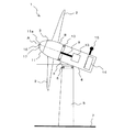
【課題】ブレードの後流の影響を受けていない風向風速の測定値に基づいて風力発電装置の運転を制御する。【解決手段】ブレード2を放射状に支持するハブ8と、ハブ8の一端部に固定された略円錐状のノーズコーン11と、を有するロータ3と、ロータ3をロータ軸A回りに回転可能に支持するナセル4と、ナセル4を水平方向に旋回させるためのヨー駆動部6と、ノーズコーン11を風上に向けるべくヨー駆動部6を制御する制御部14と、を備える。ノーズコーン11には、第1の圧力測定部16と第2の圧力測定部17とが設けられる。第1の圧力測定部16は、ノーズコーン11の先端部11aに設けられ、第2の圧力測定部17は、先端部11aからハブ8側に離間させてノーズコーン11に設けられる。制御部14は、第1の圧力測定部16及び第2の圧力測定部17による圧力測定値に基づいてヨー駆動部6を制御する。【選択図】図1Operation of a wind turbine generator is controlled based on a measured value of wind direction and wind speed that is not affected by the wake of a blade. A rotor 3 having a hub 8 that radially supports a blade 2, a substantially conical nose cone 11 fixed to one end of the hub 8, and a rotor 3 that is rotatable about a rotor axis A. A nacelle 4 to be supported, a yaw drive unit 6 for turning the nacelle 4 in the horizontal direction, and a control unit 14 for controlling the yaw drive unit 6 to direct the nose cone 11 to the windward are provided. The nose cone 11 is provided with a first pressure measuring unit 16 and a second pressure measuring unit 17. The first pressure measurement unit 16 is provided at the tip portion 11a of the nose cone 11, and the second pressure measurement unit 17 is provided at the nose cone 11 so as to be separated from the tip portion 11a toward the hub 8 side. The control unit 14 controls the yaw driving unit 6 based on the pressure measurement values obtained by the first pressure measurement unit 16 and the second pressure measurement unit 17. [Selection] Figure 1

Description

本発明の実施形態は、風力発電技術に関し、より詳細には、風力発電装置及び風力発電施設の運転制御方法に関する。   Embodiments described herein relate generally to wind power generation technology, and more particularly, to a wind power generation apparatus and a wind power generation facility operation control method.

近年、再生可能エネルギーの一つとして風力を利用した風力発電装置の普及が進んでいる。風力発電装置は、風の運動エネルギーをブレードを含むロータの回転エネルギーに変換し、さらにこの回転エネルギーを発電機にて電力に変換する。   In recent years, wind power generators using wind power as one of renewable energies have been spreading. The wind turbine generator converts kinetic energy of wind into rotational energy of a rotor including blades, and further converts this rotational energy into electric power by a generator.

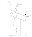
従来の風力発電装置について図14を用いて説明する。風力発電装置40は、複数のブレード41が取付けられたロータ42を回転可能に支持するナセル43の上部に風向風速計44を備えている。この風向風速計44により、風力発電装置40の設置面45に対して水平方向の風向風速が測定され、その測定値に基づいて、ロータ42が風上に向くようにナセル43を水平方向に旋回させるヨー制御や、最も揚力が発生するようにブレード41のピッチ角を制御するピッチ角制御がなされる。   A conventional wind turbine generator will be described with reference to FIG. The wind power generator 40 includes an anemometer 44 on an upper portion of a nacelle 43 that rotatably supports a rotor 42 to which a plurality of blades 41 are attached. The wind direction anemometer 44 measures the wind direction wind speed in the horizontal direction with respect to the installation surface 45 of the wind power generator 40, and the nacelle 43 is turned in the horizontal direction so that the rotor 42 faces upwind based on the measured value. Yaw control to be performed and pitch angle control to control the pitch angle of the blade 41 so as to generate the most lift force are performed.

また、風力発電装置の前方の風向風速をレーザ式風向風速計で測定することで、風力発電装置に到達する風向風速を予測し、風力発電装置の発電効率の向上を図る技術が提案されている。そこでは、風力発電装置40の前方に存在するエアロゾル(空気中の塵)の風向風速をレーザ式風向風速計で測定し、その測定データから風力発電装置40が数秒乃至数十秒後に利用する風の状況を予測し、その予測結果に基づいてナセル43のヨー制御やピッチ角制御を実施している。   In addition, a technique has been proposed in which the wind direction wind speed in front of the wind power generator is measured with a laser-type anemometer to predict the wind direction wind speed reaching the wind power generator and the power generation efficiency of the wind power generator is improved. . There, the wind direction wind speed of the aerosol (dust in the air) existing in front of the wind power generator 40 is measured with a laser type anemometer, and the wind data that the wind power generator 40 uses after several seconds to several tens of seconds from the measured data. The yaw control and pitch angle control of the nacelle 43 are performed based on the prediction result.

特開2004−285858号公報JP 2004-285858 A

従来のナセル43の上部に設置されたレーザ式風向風速計等の風向風速計は、回転するブレード41の後流の影響を少なからず受けることになる。そのため、別途風向風速計用のタワーを建てるなどして、風車ブレード41の後流の影響を全く受けない位置にレーザ式風向風速計を設けることも考えられるが、風力発電装置40の建設コスト及び運用コストの大幅な増大を招くことになり実用的ではない。   An anemometer such as a laser-type anemometer installed at the upper part of the conventional nacelle 43 is influenced by the wake of the rotating blade 41 to some extent. For this reason, it is conceivable to install a laser-type anemometer at a position that is not affected by the wake of the wind turbine blade 41 by building a separate anemometer tower. This will cause a significant increase in operating costs and is not practical.

また、ナセル43の上部に設置された風向風速計では風力発電装置40の設置面45に対して垂直方向の風速を測定することができないため、地形の影響等で地面側から吹き上がる風や逆に地面側に吹き下ろす風が発生した場合でも、その風速成分を検知することができない。このため、地面側から吹き上がる強風などが発生した場合に、風力発電装置40の故障や破損を未然に防止するべく、ロータ3の回転を停止させたり回転速度を減じたりする予防保全制御を行うことができない。   In addition, since the anemometer installed at the upper part of the nacelle 43 cannot measure the wind speed in the direction perpendicular to the installation surface 45 of the wind power generator 40, the wind blowing from the ground side due to the influence of topography or the like Even when wind blows down on the ground side, the wind speed component cannot be detected. For this reason, when strong winds blown from the ground side occur, preventive maintenance control is performed to stop the rotation of the rotor 3 or reduce the rotation speed in order to prevent the wind power generator 40 from being broken or damaged. I can't.

さらに、レーザ式風向風速計は、エアロゾルにレーザ光を照射し、その反射光を検出することにより風向風速を測定するものであるため、風向風速の測定精度がエアロゾルの存在状況によって左右されるという課題がある。   Furthermore, the laser-type anemometer measures the wind direction and the wind speed by irradiating the aerosol with laser light and detecting the reflected light. There are challenges.

本発明の実施形態は、上述した課題を解決するためになされたものであり、その目的は、風向風速をブレードの後流の影響を受けることなく測定し、その測定値に基づいて予防保全制御を含む運転制御を行うことができる風力発電装置及び風力発電施設の運転制御方法を提供することにある。   An embodiment of the present invention is made to solve the above-described problem, and an object thereof is to measure the wind direction and wind speed without being influenced by the wake of the blade, and to perform preventive maintenance control based on the measured value. It is providing the operation control method of the wind power generator and wind power generation facility which can perform operation control including this.

上記課題を解決するために、本発明の実施形態に係る風力発電装置は、ブレードを放射状に支持するハブと、当該ハブの一端部に固定されたノーズコーンと、を有するロータと、前記ロータをロータ軸回りに回転可能に支持するナセルと、前記ナセルの方向を制御するための制御部と、前記ノーズコーンの先端部及び周面部にそれぞれ設けられた第1の圧力測定部及び第2の圧力測定部と、を有することを特徴とする。   In order to solve the above problems, a wind turbine generator according to an embodiment of the present invention includes a rotor that radially supports a blade, a rotor having a nose cone fixed to one end of the hub, and the rotor. A nacelle that is rotatably supported around the rotor axis, a control unit for controlling the direction of the nacelle, a first pressure measuring unit and a second pressure provided at the tip and peripheral surfaces of the nose cone, respectively. And a measuring unit.

また、本発明の実施形態に係る風力発電施設の運転制御方法は、本発明の実施形態に係る風力発電装置を少なくとも1以上有する風力発電施設の運転制御方法であって、前記風力発電装置に設けられた第1の圧力測定部及び第2の圧力測定部で測定された風向風速データに基づいて、前記風力発電施設の全ての風力発電装置の運転を制御することを特徴とする。   An operation control method for a wind power generation facility according to an embodiment of the present invention is an operation control method for a wind power generation facility including at least one wind power generation device according to an embodiment of the present invention, and is provided in the wind power generation device. Based on the wind direction and wind speed data measured by the first pressure measurement unit and the second pressure measurement unit, the operation of all wind power generation devices of the wind power generation facility is controlled.

本発明によれば、ブレードの後流の影響を受けることなく風向風速を測定し、その測定値に基づいて風力発電装置及び風力発電施設の運転制御を行うことで、風力発電効率を向上させることができる。   According to the present invention, it is possible to improve wind power generation efficiency by measuring the wind direction and wind speed without being affected by the wake of the blade and performing operation control of the wind power generation apparatus and the wind power generation facility based on the measured value. Can do.

第1の実施形態に係る風力発電装置の概念図。The conceptual diagram of the wind power generator which concerns on 1st Embodiment. (A)は第1の実施形態に係る風力発電装置のロータの先端部の構造を示す正面図、(B)は(A)のI−I断面図、(C)は(A)のII−II断面図。(A) is a front view which shows the structure of the front-end | tip part of the rotor of the wind power generator which concerns on 1st Embodiment, (B) is II sectional drawing of (A), (C) is II- of (A). II sectional drawing. (A)は第2の圧力測定部が第1の圧力測定部に対して水平方向左側に位置した状態を示す正面図、(B)は第2の圧力測定部が第1の圧力測定部に対して水平方向右側に位置した状態を示す正面図、(C)は第2の圧力測定部が第1の圧力測定部に対して水平方向上側に位置した状態を示す正面図、(D)は第2の圧力測定部が第1の圧力測定部に対して水平方向下側に位置した状態を示す正面図。(A) is a front view showing a state in which the second pressure measuring unit is located on the left side in the horizontal direction with respect to the first pressure measuring unit, and (B) is a diagram showing the second pressure measuring unit as the first pressure measuring unit. The front view which shows the state located in the horizontal direction right side with respect to (C) is a front view which shows the state where the 2nd pressure measurement part was located in the horizontal direction upper side with respect to the 1st pressure measurement part, (D) is The front view which shows the state which the 2nd pressure measurement part was located in the horizontal direction lower side with respect to the 1st pressure measurement part. (A)は第2の実施形態に係る風力発電装置のロータの先端部の構造を示す正面図、(B)は(A)のI−I断面図、(C)は(A)のII−II断面図。(A) is a front view which shows the structure of the front-end | tip part of the rotor of the wind power generator concerning 2nd Embodiment, (B) is II sectional drawing of (A), (C) is II- of (A). II sectional drawing. (A)は第2の実施形態の変形例1を示す正面図、(B)は(A)のI−I断面図、(C)は(A)のII−II断面図。(A) is a front view which shows the modification 1 of 2nd Embodiment, (B) is II sectional drawing of (A), (C) is II-II sectional drawing of (A). (A)は第3の実施形態に係る風力発電装置のロータの先端部の構造を示す正面図、(B)は(A)のI−I断面図、(C)は(A)のII−II断面図。(A) is a front view which shows the structure of the front-end | tip part of the rotor of the wind power generator concerning 3rd Embodiment, (B) is II sectional drawing of (A), (C) is II- of (A). II sectional drawing. (A)は第4の実施形態に係る風力発電装置のロータの先端部の構造を示す正面図、(B)は(A)のI−I断面図、(C)は(A)のII−II断面図。(A) is a front view which shows the structure of the front-end | tip part of the rotor of the wind power generator concerning 4th Embodiment, (B) is II sectional drawing of (A), (C) is II- of (A). II sectional drawing. 第5の実施形態に係る風力発電装置のロータの先端部の構造を示す断面図。Sectional drawing which shows the structure of the front-end | tip part of the rotor of the wind power generator which concerns on 5th Embodiment. 第5の実施形態の変形例2を示す断面図。Sectional drawing which shows the modification 2 of 5th Embodiment. 第6の実施形態に係る風力発電施設の運転制御システムの概念図。The conceptual diagram of the operation control system of the wind power generation facility which concerns on 6th Embodiment. 第7の実施形態に係る風力発電施設の運転制御システムの概念図。The conceptual diagram of the operation control system of the wind power generation facility which concerns on 7th Embodiment. 第7の実施形態の変形例3を示す概念図。The conceptual diagram which shows the modification 3 of 7th Embodiment. 第8の実施形態に係る風力発電施設の運転制御システムの概念図。The conceptual diagram of the operation control system of the wind power generation facility which concerns on 8th Embodiment. 従来の風力発電装置の概念図。The conceptual diagram of the conventional wind power generator.

以下、本発明の風力発電装置及び風力発電施設の運転制御方法の実施形態について添付図面を参照して説明する。
[第1の実施形態]
第1の実施形態に係る風力発電装置を、図1乃至図3を用いて説明する。
DESCRIPTION OF EMBODIMENTS Hereinafter, embodiments of a wind power generation apparatus and a wind power generation facility operation control method of the present invention will be described with reference to the accompanying drawings.
[First Embodiment]
A wind turbine generator according to a first embodiment will be described with reference to FIGS. 1 to 3.

(構成)
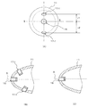
図1に示すように、風力発電装置1は、ブレード2を備えたロータ3と、ロータ3をロータ軸A回りに回転可能に支持するナセル4と、ナセル4を略水平方向(ヨー角方向)に旋回可能に支持するタワー5と、を有する。ナセル4は、ヨー駆動部6を介してタワー5の上端部に支持されている。タワー5は、設置面7から略鉛直に延びている。タワー5は、陸上であれば基礎に設置され、洋上であれば海底に設置されている基礎に接合、或いは海面付近に浮かんだ浮体基礎等に接合される。
(Constitution)
As shown in FIG. 1, a wind turbine generator 1 includes a rotor 3 provided with blades 2, a nacelle 4 that supports the rotor 3 so as to be rotatable about a rotor axis A, and the nacelle 4 in a substantially horizontal direction (yaw angle direction). And a tower 5 that is pivotally supported. The nacelle 4 is supported on the upper end portion of the tower 5 via the yaw driving unit 6. The tower 5 extends substantially vertically from the installation surface 7. The tower 5 is installed on a foundation if it is on land, and is joined to a foundation that is installed on the seabed, or a floating foundation that floats near the sea surface if it is offshore.

ロータ3は、ブレード2を放射状に支持するハブ8と、ハブ8に連結された主軸9とを有する。ハブ8は、主軸受10を介してナセル4に支持されている。ハブ8の先端部にはノーズコーン(略円錐状の先端部材)11が固定されている。   The rotor 3 includes a hub 8 that radially supports the blades 2 and a main shaft 9 that is coupled to the hub 8. The hub 8 is supported by the nacelle 4 via the main bearing 10. A nose cone (substantially conical tip member) 11 is fixed to the tip of the hub 8.

ナセル4は、ロータ3側が高くなるよう所定の角度(チルト角θ)だけ傾いた姿勢に保持されている。ナセル4の内部には、ロータ3の主軸9の回転に伴って駆動される発電機13と、風力発電装置1の運転を制御する制御部14と、が設けられている。また、ナセル4の後端側の上部には、従来と同様の風向風速計15が設けられている。風向風速計15による風向風速測定データは制御部14に送信される。   The nacelle 4 is held in a posture inclined by a predetermined angle (tilt angle θ) so that the rotor 3 side becomes higher. Inside the nacelle 4, a generator 13 that is driven as the main shaft 9 of the rotor 3 rotates and a control unit 14 that controls the operation of the wind power generator 1 are provided. An anemometer 15 similar to the conventional one is provided at the upper part of the rear end side of the nacelle 4. Wind direction wind speed measurement data from the wind direction anemometer 15 is transmitted to the control unit 14.

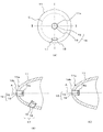
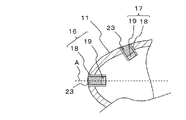
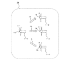
図2に示すように、ノーズコーン11には、第1の圧力測定部16と第2の圧力測定部17とが設けられている。第1の圧力測定部16は、ノーズコーン11の先端部11aに設けられ、第2の圧力測定部17は、第1の圧力測定部16からハブ8側に所定距離離間させてノーズコーン11の周面部に設けられている。   As shown in FIG. 2, the nose cone 11 is provided with a first pressure measuring unit 16 and a second pressure measuring unit 17. The first pressure measurement unit 16 is provided at the distal end portion 11a of the nose cone 11, and the second pressure measurement unit 17 is separated from the first pressure measurement unit 16 by a predetermined distance toward the hub 8 side. It is provided on the peripheral surface.

第1の圧力測定部16及び第2の圧力測定部17は、ノーズコーン11の外面から内部に延在して設けられた圧力導通管18と、圧力導通管18の内部側の端部18aに設けられた感圧素子19と、を各々備えている。圧力導通管18のもう一方の端部18bは圧力導通管18の外部に開口しており、圧力導通管18内は外気で満たされている。感圧素子19は、圧力導通管18内の圧力値に応じた電気信号を出力する。その電気信号が圧力測定データとして制御部14に送信される。   The first pressure measurement unit 16 and the second pressure measurement unit 17 are provided on a pressure conducting pipe 18 extending from the outer surface of the nose cone 11 and an end 18 a on the inner side of the pressure conducting pipe 18. And a pressure-sensitive element 19 provided. The other end 18b of the pressure conducting pipe 18 opens to the outside of the pressure conducting pipe 18, and the inside of the pressure conducting pipe 18 is filled with outside air. The pressure sensitive element 19 outputs an electrical signal corresponding to the pressure value in the pressure conducting tube 18. The electric signal is transmitted to the control unit 14 as pressure measurement data.

なお、風向風速計15は適宜省略可能であるが、第1及び第2の圧力測定部16、17と併用し、例えば、風向風速計15は基本的な風向風速データの取得のために利用し、ブレードの後流の影響を受けない第1及び第2の圧力測定部16、17は垂直流や精密な風向風速データの取得に利用するようにしてもよい。   Although the wind direction anemometer 15 can be omitted as appropriate, it is used in combination with the first and second pressure measuring units 16 and 17, for example, the wind direction anemometer 15 is used for acquiring basic wind direction anemometer data. The first and second pressure measuring units 16 and 17 that are not affected by the wake of the blade may be used for acquiring the vertical flow and precise wind direction and wind speed data.

(作用)
上記のように構成された風力発電装置1は、風の運動エネルギーを、ブレード2を備えたロータ3の回転エネルギーに変換し、この回転エネルギーを発電機13にて電力に変換することにより発電を行う。
(Function)
The wind turbine generator 1 configured as described above converts wind kinetic energy into rotational energy of the rotor 3 provided with the blades 2 and converts the rotational energy into electric power by the generator 13 to generate electric power. Do.

その際、ナセル4が正面から受ける風の圧力値が第1の圧力測定部16により測定され、第1の圧力測定部16よりも少し下流側の風の圧力値が第2の圧力測定部17により測定される。第1の圧力測定部16及び第2の圧力測定部17はブレード2の上流側に位置しているため、これらによる測定値はブレード2の回転に伴う後流の影響を受けない、本来測定されるべき風の圧力測定値である。   At that time, the pressure value of the wind received by the nacelle 4 from the front is measured by the first pressure measuring unit 16, and the pressure value of the wind slightly downstream from the first pressure measuring unit 16 is the second pressure measuring unit 17. Measured by Since the first pressure measurement unit 16 and the second pressure measurement unit 17 are located on the upstream side of the blade 2, the measurement values obtained by these are not affected by the wake that accompanies the rotation of the blade 2 and are originally measured. This is the measured value of wind pressure.

また、第2の圧力測定部17は、ノーズコーン11とともにロータ軸A回りに回転するため、その感圧素子19の中心の回転軌跡が描くノーズコーン11の円周C上の所定位置における圧力を測定し、その値に基づいて風向を検知することができる。   Further, since the second pressure measuring unit 17 rotates around the rotor axis A together with the nose cone 11, the pressure at a predetermined position on the circumference C of the nose cone 11 drawn by the rotation locus of the center of the pressure sensitive element 19 is measured. The wind direction can be detected based on the measured value.

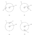
例えば、第2の圧力測定部17が第1の圧力測定部16に対し水平方向左側(図3(A)参照)及び右側(図3(B)参照)に位置したときの二つの圧力測定値に基づいて、ナセル4のヨー角に対する風向を検知できる。また、第2の圧力測定部17が第1の圧力測定部16に対し垂直方向上側(図3(C)参照)及び下側(図3(D)参照)に位置したときの二つの圧力測定値に基づいて、ナセル4のチルト角θに対する風向(吹き上げ角、吹き下ろし角)を検知することができる。   For example, two pressure measurement values when the second pressure measurement unit 17 is positioned on the left side in the horizontal direction (see FIG. 3A) and the right side (see FIG. 3B) with respect to the first pressure measurement unit 16. Based on the above, the wind direction with respect to the yaw angle of the nacelle 4 can be detected. In addition, two pressure measurements when the second pressure measurement unit 17 is positioned vertically above (see FIG. 3C) and below (see FIG. 3D) the first pressure measurement unit 16. Based on the value, it is possible to detect the wind direction (blow-up angle, blow-down angle) with respect to the tilt angle θ of the nacelle 4.

このように、第1の圧力測定部16によるノーズコーン11の先端部11aにおける圧力測定値と、第2の圧力測定部17によるノーズコーン11の左右及び上下位置における四つの圧力測定値と、に基づいて、風力発電装置1の設置位置における複数方向からの風向風速を算出することができる。   Thus, the pressure measurement value at the tip 11a of the nose cone 11 by the first pressure measurement unit 16 and the four pressure measurement values at the left and right and vertical positions of the nose cone 11 by the second pressure measurement unit 17 are as follows. Based on this, wind directions and wind speeds from a plurality of directions at the installation position of the wind turbine generator 1 can be calculated.

また、ノーズコーン11の先端及び上下左右の四つの圧力値と風向風速との関係を予め評価したデータベースを作成しておき、第2の圧力測定部17がノーズコーン11の左右及び上下に位置した各々の時点での第1の圧力測定部16及び第2の圧力測定部17による圧力測定値に対応する風向風速を当該データベースから逐次読み出すことにより、複雑な計算を要することなく、風力発電装置1の設置位置における複数方向からの風向風速を取得することができる。
制御部14は、上記のようにして得られた風向風速に基づいて、ナセル4のヨー角及びピッチ角を適切な値に制御する。
Moreover, the database which evaluated beforehand the relationship between the front-end | tip of the nose cone 11, and four pressure values of up-down, left-right, and wind direction wind speed was created, and the 2nd pressure measurement part 17 was located in the left-right and up-down of the nose cone 11. By sequentially reading out the wind direction and the wind speed corresponding to the pressure measurement values by the first pressure measurement unit 16 and the second pressure measurement unit 17 at each time point from the database, the wind turbine generator 1 does not require complicated calculation. It is possible to acquire wind directions and wind speeds from a plurality of directions at the installation position.
The control unit 14 controls the yaw angle and pitch angle of the nacelle 4 to appropriate values based on the wind direction and wind speed obtained as described above.

(効果)
第1の実施形態に係る風力発電装置1によれば、ノーズコーン11の先端部及び周面部に圧力測定部16、17を設けることにより、ナセル4に対して正面方向、水平方向及び垂直方向の風速成分をブレード2の後流の影響を受けることなく測定することが可能となり、これにより風のエネルギーを効率良くロータ3の回転エネルギーに変換し得るように運転制御を行うことができる。
(effect)
According to the wind turbine generator 1 according to the first embodiment, the pressure measuring units 16 and 17 are provided on the tip portion and the peripheral surface portion of the nose cone 11, so that the nacelle 4 has a front direction, a horizontal direction, and a vertical direction. The wind speed component can be measured without being influenced by the wake of the blade 2, and thus the operation control can be performed so that the wind energy can be efficiently converted into the rotational energy of the rotor 3.

また、ナセル4に対して垂直方向の風向を検知することができるので、過大な風速の垂直成分を検知した場合に、ロータ3を停止させたり、ロータ3の回転速度を減じたりする制御をより正確に行うことが可能となる。よって、風力発電装置1の故障や破損を未然に防止することができる。   Further, since the wind direction in the vertical direction with respect to the nacelle 4 can be detected, when the vertical component of the excessive wind speed is detected, the control of stopping the rotor 3 or reducing the rotation speed of the rotor 3 is further performed. It becomes possible to carry out accurately. Therefore, failure and damage of the wind power generator 1 can be prevented in advance.

また、ノーズコーン11の左右位置及び上下位置における圧力を、ノーズコーン11の周面部に設けた一つの第2の圧力測定部17により測定可能としたことにより、ブレード2の回転に伴う後流の影響を受けることなく風向風速を測定するためのシステム構成を単純なものとすることができる。   In addition, since the pressure at the left and right positions and the vertical position of the nose cone 11 can be measured by one second pressure measurement unit 17 provided on the peripheral surface portion of the nose cone 11, the wake flow associated with the rotation of the blade 2 can be measured. The system configuration for measuring the wind direction and wind speed without being affected can be simplified.

[第2の実施形態]
第2の実施形態に係る風力発電装置を、図4(A)〜(C)を用いて説明する。風力発電装置の全体的構成については、図1に示したものと同様であるので、以下説明を省略する。また、既に説明した構成要素と共通の構成要素については同一符号を付してその説明を適宜省略する(以下同様)。
[Second Embodiment]
A wind turbine generator according to a second embodiment will be described with reference to FIGS. The overall configuration of the wind turbine generator is the same as that shown in FIG. In addition, constituent elements that are the same as those already described are assigned the same reference numerals, and the description thereof is omitted as appropriate (the same applies hereinafter).

(構成)
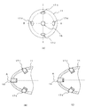
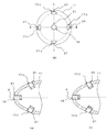
上述した第1の実施形態では、一つの第2の圧力測定部17がノーズコーン11の周面部に設けられているが、この第2の実施形態では、二つの第2の圧力測定部17-1、17-2がノーズコーン11の周面部に、ロータ軸Aに関して180度で回転対称となるように設けられている。第2の圧力測定部17-1、17-2の構成は、図2に示した第2の圧力測定部17の構成と同様である。
(Constitution)
In the first embodiment described above, one second pressure measurement unit 17 is provided on the peripheral surface portion of the nose cone 11, but in the second embodiment, two second pressure measurement units 17- 1 and 17-2 are provided on the peripheral surface portion of the nose cone 11 so as to be rotationally symmetric with respect to the rotor axis A at 180 degrees. The configurations of the second pressure measurement units 17-1 and 17-2 are the same as the configuration of the second pressure measurement unit 17 shown in FIG.

(作用)
上記のように、第2の圧力測定部17-1、17-2が、第1の圧力測定部16からハブ8側に所定距離離間させて、ノーズコーン11のロータ軸Aに関して180度で回転対称となる二か所に設けられていることにより、左右二位置若しくは上下二位置の圧力をそれぞれ同時に測定することができる。したがって、設置面7に対して水平方向及び垂直方向の風向風速データを、第1の実施形態と比較して短い周期で取得することが可能となるとともに、風向風速の変化を高精度で測定することができる。
(Function)
As described above, the second pressure measuring units 17-1 and 17-2 are rotated by 180 degrees with respect to the rotor axis A of the nose cone 11 by being separated from the first pressure measuring unit 16 by a predetermined distance toward the hub 8. By being provided at two symmetrical positions, it is possible to simultaneously measure the pressures at the two left and right positions or the two upper and lower positions. Therefore, it becomes possible to acquire the wind direction wind speed data in the horizontal direction and the vertical direction with respect to the installation surface 7 with a shorter period than in the first embodiment, and measure the change in the wind direction wind speed with high accuracy. be able to.

すなわち、第2の実施形態の構成では、二つの第2の圧力測定部17-1、17-2は、ロータ3が半回転するために要する時間間隔でナセル4に対して水平及び垂直方向の風向風速を取得することができる。   That is, in the configuration of the second embodiment, the two second pressure measuring units 17-1 and 17-2 are arranged in the horizontal and vertical directions with respect to the nacelle 4 at a time interval required for the rotor 3 to make a half rotation. The wind direction and wind speed can be acquired.

(効果)
第2の実施形態に係る風力発電装置1によれば、ナセル4に対して水平方向及び垂直方向の風速成分を、第1の実施形態よりも短い周期で測定可能であるので、その測定値に基づいて、風のエネルギーをより効率良くロータ3の回転エネルギーに変換し得るように、ナセル4のヨー角及びブレード2のピッチ角をより適切に調整することができる。
(effect)
According to the wind turbine generator 1 according to the second embodiment, the wind speed component in the horizontal direction and the vertical direction can be measured with respect to the nacelle 4 in a shorter cycle than in the first embodiment. Based on this, the yaw angle of the nacelle 4 and the pitch angle of the blades 2 can be adjusted more appropriately so that the wind energy can be converted into the rotational energy of the rotor 3 more efficiently.

また、垂直方向の風向の検知感度の向上及び検出時間の短縮を図ることができるので、過大な風速の垂直成分を検知した場合に、風力発電装置1の故障や破損の予防保全として、ロータ3を停止させたり、ロータ3の回転速度を減じたりする制御をより迅速にかつ正確に行うことが可能となる。   Further, since the detection sensitivity of the vertical wind direction can be improved and the detection time can be shortened, the rotor 3 can be used as preventive maintenance for failure or breakage of the wind power generator 1 when the vertical component of excessive wind speed is detected. It is possible to perform control more quickly and accurately to stop the control or to reduce the rotational speed of the rotor 3.

(変形例1)
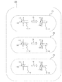
上述した第2の実施形態では、ノーズコーン11の周面部に二つの第2の圧力測定部17-1、17-2がノーズコーン11に設けられているが、本変形例1では、図5(A)〜(C)に示すように、四つの第2の圧力測定部17-1〜17-4がノーズコーン11の周面部に設けられている。第2の圧力測定部17-1〜17-4の構成は、図2に示した第2の圧力測定部17の構成と同様である。
(Modification 1)
In the second embodiment described above, two second pressure measuring units 17-1 and 17-2 are provided on the nose cone 11 on the peripheral surface portion of the nose cone 11. However, in the first modification, FIG. As shown in (A) to (C), four second pressure measuring portions 17-1 to 17-4 are provided on the peripheral surface portion of the nose cone 11. The configuration of the second pressure measuring units 17-1 to 17-4 is the same as the configuration of the second pressure measuring unit 17 shown in FIG.

この第2の圧力測定部17-1〜17-4は、ノーズコーン11の先端部から等距離で、かつ、ロータ軸Aに関して90°で回転対称となるように設けられている。
本変形例1では、設置面7に対して水平方向及び垂直方向の風向風速を、第2の実施形態よりも更に短い周期で取得することが可能となる。
The second pressure measuring units 17-1 to 17-4 are provided so as to be equidistant from the tip of the nose cone 11 and to be rotationally symmetric at 90 ° with respect to the rotor axis A.
In the first modification, it is possible to acquire the wind direction and wind speed in the horizontal direction and the vertical direction with respect to the installation surface 7 at a cycle shorter than that in the second embodiment.

すなわち、第2の実施形態の構成では、ロータ3が90°回転する毎に二つの第2の圧力測定部17-1、17-2により同時に測定される左右二箇所若しくは上下二箇所のそれぞれ二つの圧力測定値に基づいて、設置面7に対して水平方向の風向風速と設置面7に対して垂直方向の風向風速とが交互に取得されるのに対し、この変形例1では、第1の圧力測定部16に対し上下左右の四箇所の圧力が同時に測定されるため、設置面7に対して水平方向及び垂直方向の風向風速を、ロータ3が90°回転する毎に一括して取得できる。   That is, in the configuration of the second embodiment, each time the rotor 3 is rotated 90 °, the two second pressure measuring units 17-1 and 17-2 are simultaneously measured at two left and right or two upper and lower positions. On the basis of two pressure measurement values, the wind direction wind speed in the horizontal direction with respect to the installation surface 7 and the wind direction wind speed in the direction perpendicular to the installation surface 7 are alternately obtained. Since the pressure at the four locations on the top, bottom, left, and right is simultaneously measured with respect to the pressure measuring unit 16, the wind direction and the wind speed in the horizontal direction and the vertical direction with respect to the installation surface 7 are collectively acquired every time the rotor 3 rotates 90 °. it can.

したがって、設置面7に対して水平方向及び垂直方向の風向風速を、第2の実施形態と比較して理論上1/2の周期で、第1の実施形態と比較して理論上1/4の周期で取得することが可能となる。   Therefore, the wind direction and the wind speed in the horizontal direction and the vertical direction with respect to the installation surface 7 are theoretically ¼ compared with the first embodiment and theoretically ¼ compared with the second embodiment. It becomes possible to acquire with the period of.

本変形例1によれば、設置面7に対して水平方向及び垂直方向の風速成分を、第2の実施形態よりも更に短い周期で測定可能であるので、風向風速成分の変化を高精度で測定することができる。これにより、風のエネルギーを更に効率良くロータ3の回転エネルギーに変換し得るように運転制御を行うことができる。   According to the first modification, the wind speed component in the horizontal direction and the vertical direction with respect to the installation surface 7 can be measured with a shorter cycle than in the second embodiment, and therefore the change in the wind direction wind speed component can be performed with high accuracy. Can be measured. Thereby, operation control can be performed so that wind energy can be more efficiently converted into rotational energy of the rotor 3.

また、ノーズコーン11の上下二箇所の圧力を同時測定される周期が第2の実施形態よりも短いことにより、設置面7に対して垂直方向の風向の検知感度を第2の実施形態よりも更に向上させることができる。したがって、過大な風速の垂直成分を検知した場合に、風力発電装置1の故障や破損の予防保全として、ロータ3を停止させたり、ロータ3の回転速度を減じたりする制御を更に正確に行うことが可能となる。
なお、第2の圧力測定部の数は1、2又は4に限定されず、適宜増減可能である。
In addition, since the cycle in which the pressures at the top and bottom of the nose cone 11 are simultaneously measured is shorter than that of the second embodiment, the detection sensitivity of the wind direction in the direction perpendicular to the installation surface 7 is higher than that of the second embodiment. Further improvement can be achieved. Therefore, when the vertical component of excessive wind speed is detected, control for stopping the rotor 3 or reducing the rotational speed of the rotor 3 is performed more accurately as preventive maintenance for failure or breakage of the wind turbine generator 1. Is possible.
The number of second pressure measuring units is not limited to 1, 2, or 4, and can be increased or decreased as appropriate.

[第3の実施形態]
第3の実施形態に係る風力発電装置を、図6(A)〜(C)を用いて説明する。
(構成)
上述した第2の実施形態では、二つの第2の圧力測定部17-1、17-2がノーズコーン11の先端部11aからロータ軸A方向に等距離の位置に設けられているが、この第3の実施形態では、二つの第2の圧力測定部17-1、17-2がノーズコーン11の先端部11aからロータ軸A方向に異なった距離の位置に設けられている。
[Third Embodiment]
A wind turbine generator according to a third embodiment will be described with reference to FIGS.
(Constitution)
In the second embodiment described above, the two second pressure measuring units 17-1 and 17-2 are provided at equidistant positions from the tip 11a of the nose cone 11 in the direction of the rotor axis A. In the third embodiment, the two second pressure measurement units 17-1 and 17-2 are provided at different distances from the tip end part 11 a of the nose cone 11 in the rotor axis A direction.

図6(A)に示す例では、一方の第2の圧力測定部17-1の感圧素子19の中心の回転軌跡が描く円周C1の半径r1に対し、もう一方の第2の圧力測定部17-2の感圧素子19の中心の回転軌跡が描く円周C2の半径r2の方が大きくなっている。   In the example shown in FIG. 6A, the other second pressure measurement is performed with respect to the radius r1 of the circumference C1 drawn by the rotation locus of the center of the pressure-sensitive element 19 of the second pressure measurement unit 17-1. The radius r2 of the circumference C2 drawn by the rotation locus of the center of the pressure-sensitive element 19 of the portion 17-2 is larger.

(作用)
上記のように、ロータ軸A方向における二つの第2の圧力測定部17-1、17-2のロータ軸A方向における位置を異ならせることにより、第2の実施形態の構成と比較して、二つの第2の圧力測定部17-1、17-2による圧力の測定範囲が広がる。
(Function)
As described above, by making the positions of the two second pressure measurement units 17-1 and 17-2 in the rotor axis A direction different in the rotor axis A direction, compared with the configuration of the second embodiment, The measurement range of pressure by the two second pressure measuring units 17-1 and 17-2 is expanded.

(効果)
第3の実施形態に係る風力発電装置1によれば、設置面7に対して水平方向及び垂直方向の風速成分を、第2の実施形態よりも広範囲に測定可能であるので、その測定値に基づいて、風のエネルギーをより効率良くロータ3の回転エネルギーに変換し得るように、ナセル4のヨー角及びブレード2のピッチ角をより適切に調整することができる。
また、設置面7に対して垂直方向の風速成分の測定範囲が拡大したことにより、より大きな風向変化に対しても、その垂直方向の風速成分を測定することが可能となる。
(effect)
According to the wind turbine generator 1 according to the third embodiment, the wind speed component in the horizontal direction and the vertical direction can be measured in a wider range than the second embodiment with respect to the installation surface 7. Based on this, the yaw angle of the nacelle 4 and the pitch angle of the blades 2 can be adjusted more appropriately so that the wind energy can be converted into the rotational energy of the rotor 3 more efficiently.
Further, since the measurement range of the wind speed component in the vertical direction with respect to the installation surface 7 is expanded, the wind speed component in the vertical direction can be measured even when the wind direction changes more greatly.

したがって、本実施形態の風力発電装置1は、地形の影響等で地面側から吹き上がる風や逆に地面側に吹き下ろす風が急に発生したり、その風向きが急に変化したりすることが想定される地点への設置に適している。
なお、本第3の実施形態を上記変形例にも適用できることはもちろんである。
Therefore, the wind power generator 1 of the present embodiment may suddenly generate wind that blows up from the ground side due to the influence of topography or the like, or conversely winds down to the ground side, or the wind direction may change suddenly. It is suitable for installation at an assumed point.
Needless to say, the third embodiment can also be applied to the above modification.

[第4の実施形態]
本実施形態では、第1の圧力測定部16及び第2の圧力測定部17の近傍にそれぞれ温度センサを配置することを特徴とする。この構成例を、図5に示す風力発電装置に適用した例について、図7を用いて説明するが、他の実施形態に係る風力発電装置にも適用することができることはもちろんである。
[Fourth Embodiment]
In the present embodiment, a temperature sensor is disposed in the vicinity of each of the first pressure measurement unit 16 and the second pressure measurement unit 17. An example in which this configuration example is applied to the wind turbine generator shown in FIG. 5 will be described with reference to FIG. 7, but it is needless to say that the configuration example can also be applied to a wind turbine generator according to another embodiment.

(構成)
図7(A)〜(C)に示すように、一つの第1の圧力測定部16及び四つの第2の圧力測定部17-1〜17-4がノーズコーン11に設けられ、第1の圧力測定部16及び第2の圧力測定部17-1〜17-4のそれぞれの近傍に温度センサ21が配置されている。温度センサ21には熱電対などが用いられる。温度センサ21による温度測定データは制御部14に送信される。
(Constitution)
As shown in FIGS. 7A to 7C, one first pressure measuring unit 16 and four second pressure measuring units 17-1 to 17-4 are provided in the nose cone 11, and the first A temperature sensor 21 is disposed in the vicinity of each of the pressure measurement unit 16 and the second pressure measurement units 17-1 to 17-4. A thermocouple or the like is used for the temperature sensor 21. Temperature measurement data from the temperature sensor 21 is transmitted to the control unit 14.

(作用)
制御部14は、各温度センサ21による温度測定データに基づいて、第1の圧力測定部16及び第2の圧力測定部17-1〜17-4による圧力測定値を補正する。そして、補正した圧力測定値に基づいて、設置面7に対して水平方向及び垂直方向の風向風速を取得する。
(Function)
The control unit 14 corrects the pressure measurement values obtained by the first pressure measurement unit 16 and the second pressure measurement units 17-1 to 17-4 based on the temperature measurement data obtained by the temperature sensors 21. And based on the corrected pressure measurement value, the wind direction wind speed of a horizontal direction and a perpendicular direction is acquired with respect to the installation surface 7. FIG.

(効果)
第4の実施形態に係る風力発電装置1によれば、設置面7に対して水平方向及び垂直方向の風速成分を、季節や天候などによる温度変化の影響を受けることなく高精度に測定し、その測定値に基づいて的確な運転制御を行うことができる。
(effect)
According to the wind turbine generator 1 according to the fourth embodiment, the wind speed component in the horizontal direction and the vertical direction with respect to the installation surface 7 is measured with high accuracy without being affected by the temperature change due to the season or weather, Accurate operation control can be performed based on the measured value.

[第5の実施形態]
第5の実施形態に係る風力発電装置を、図8を用いて説明するが、上述した他の実施形態の風力発電装置にも適用できることはもちろんである。
[Fifth Embodiment]
The wind turbine generator according to the fifth embodiment will be described with reference to FIG. 8, but it is needless to say that the wind turbine generator of other embodiments described above can be applied.

(構成)
図8に示すように、第1の圧力測定部16及び第2の圧力測定部17のそれぞれの圧力導通管18内に粘着性の流体23が充填されている。粘着性の流体23として、高粘度の油やグリスなどが用いられる。
(Constitution)
As shown in FIG. 8, the pressure fluid pipes 18 of the first pressure measurement unit 16 and the second pressure measurement unit 17 are filled with an adhesive fluid 23. As the adhesive fluid 23, highly viscous oil or grease is used.

(作用)
圧力導通管18内に粘着性の流体23を充填したことにより、感圧素子19が外気と非接触状態となるため、雨水や砂塵などから感圧素子19を保護することができるため、感圧素子19を長期的に使用することができる。一方、ノーズコーン11外部の風向風速は流体23を介して感圧素子19に伝わることになるため、充填する流体の量は、感圧素子19による圧力測定感度が必要な値となるように選択される。
(Function)
By filling the pressure conducting pipe 18 with the adhesive fluid 23, the pressure sensitive element 19 is in a non-contact state with the outside air, so that the pressure sensitive element 19 can be protected from rain water, dust, and the like. The element 19 can be used for a long time. On the other hand, since the wind direction and the wind speed outside the nose cone 11 are transmitted to the pressure sensitive element 19 via the fluid 23, the amount of fluid to be filled is selected so that the pressure measurement sensitivity by the pressure sensitive element 19 becomes a required value. Is done.

(効果)
第5の実施形態によれば、第1の圧力測定部16及び第2の圧力測定部17の感圧素子19が雨水や砂塵などから保護されるので、第1の圧力測定部16及び第2の圧力測定部17の寿命を延ばし、これらの何れかの故障に起因する風向風速の誤検知の発生リスクを低減することが可能となる。
(effect)
According to the fifth embodiment, since the pressure sensitive elements 19 of the first pressure measuring unit 16 and the second pressure measuring unit 17 are protected from rainwater, dust, etc., the first pressure measuring unit 16 and the second pressure measuring unit 16 are protected. It is possible to extend the life of the pressure measuring unit 17 and reduce the risk of erroneous detection of the wind direction and wind speed due to any of these failures.

[変形例2]
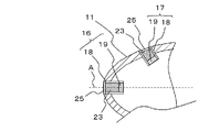
本変形例2では、図9に示すように、第1の圧力測定部16及び第2の圧力測定部17に充填された粘着性の流体23を覆うように弾性変形可能な封止体25を設けたことを特徴とする。
[Modification 2]
In the second modification, as shown in FIG. 9, a sealing body 25 that is elastically deformable so as to cover the adhesive fluid 23 filled in the first pressure measurement unit 16 and the second pressure measurement unit 17 is provided. It is provided.

封止体25として、圧力応答性に優れた薄いゴム製のダイヤフラムや蛇腹式ダイヤフラムが用いられる。
封止体25を設けたことにより、圧力導通管18内からの流体23の漏出が防止されるため、感圧素子19が雨水や砂塵などから長期間安定的に保護されるとともに、流体23の経年劣化を防止することができる。
As the sealing body 25, a thin rubber diaphragm or bellows type diaphragm excellent in pressure responsiveness is used.
By providing the sealing body 25, leakage of the fluid 23 from the pressure conducting pipe 18 is prevented, so that the pressure sensitive element 19 is stably protected from rainwater, dust, etc. for a long period of time. Aging deterioration can be prevented.

ノーズコーン11外部の風向風速は封止体25及び流体23を介して感圧素子19に伝わることになるため、封止体25の厚み及び充填する流体23の量は、感圧素子19による圧力測定感度が必要な値となるように選択される。   Since the wind direction and wind speed outside the nose cone 11 is transmitted to the pressure-sensitive element 19 via the sealing body 25 and the fluid 23, the thickness of the sealing body 25 and the amount of the fluid 23 to be filled are determined by the pressure by the pressure-sensitive element 19. The measurement sensitivity is selected to be a required value.

本変形例2によれば、第1の圧力測定部16及び第2の圧力測定部17の感圧素子19及び流体23が雨水や砂塵などから長期間安定的に保護されるので、第1の圧力測定部16及び第2の圧力測定部17-1〜17-4の寿命を更に延ばし、これらの何れかの故障に起因する風向風速の誤検知の発生リスクを更に低減することができる。   According to the second modification, the pressure sensitive element 19 and the fluid 23 of the first pressure measuring unit 16 and the second pressure measuring unit 17 are stably protected from rainwater, dust, etc. for a long period of time. The lifetime of the pressure measurement unit 16 and the second pressure measurement units 17-1 to 17-4 can be further extended, and the risk of erroneous detection of wind direction and wind speed due to any of these failures can be further reduced.

[第6の実施形態]
第6の実施形態に係る風力発電施設の運転制御方法を、図10を用いて説明する。
(構成)
図10に示す風力発電施設26は、本発明の第1〜第5の実施形態のいずれかに係る風力発電装置1と、図14に示すような従来の風力発電装置27と、から構成される。この構成例では、本発明に係る風力発電装置1は1基設置され、従来型の風力発電装置27は複数基設置され、それらの位置関係は任意である。
[Sixth Embodiment]
A wind power generation facility operation control method according to the sixth embodiment will be described with reference to FIG.
(Constitution)
A wind power generation facility 26 shown in FIG. 10 includes the wind power generation device 1 according to any one of the first to fifth embodiments of the present invention and a conventional wind power generation device 27 as shown in FIG. . In this configuration example, one wind power generator 1 according to the present invention is installed, a plurality of conventional wind power generators 27 are installed, and their positional relationship is arbitrary.

風力発電装置1は、第1の圧力測定部16及び第2の圧力測定部17により測定した圧力測定値に基づいて得られた風向風速の情報(風向風速データD)を、風力発電施設26内の他の全ての従来型の風力発電装置27に送信する機能を有している。   The wind turbine generator 1 uses the wind direction wind speed information (wind direction wind speed data D) obtained based on the pressure measurement values measured by the first pressure measurement unit 16 and the second pressure measurement unit 17 in the wind power generation facility 26. It has the function to transmit to all the other conventional wind power generators 27.

従来型の風力発電装置27は、本発明に係る風力発電装置1から風向風速データDを受信する機能と、その受信した風向風速データDに基づいて自装置のヨー角を制御する機能と、を有する。   The conventional wind turbine generator 27 has a function of receiving the wind direction wind speed data D from the wind turbine generator 1 according to the present invention and a function of controlling the yaw angle of the own device based on the received wind direction wind speed data D. Have.

(作用)
本発明に係る風力発電装置1は、第1の圧力測定部16及び第2の圧力測定部17による圧力測定値に基づいて得られた風向風速データDに基づいて、自装置のナセル4のヨー角等を制御するとともに、当該風向風速データDを、風力発電施設26内の全ての従来型の風力発電装置27に送信する。従来型の各風力発電装置27は、その風向風速データDに基づいてナセルのヨー角等を制御する。
(Function)
The wind turbine generator 1 according to the present invention is based on the wind direction and wind speed data D obtained based on the pressure measurement values obtained by the first pressure measurement unit 16 and the second pressure measurement unit 17, and the yaw of the nacelle 4 of the device itself. The angle and the like are controlled, and the wind direction wind speed data D is transmitted to all conventional wind power generators 27 in the wind power generation facility 26. Each of the conventional wind turbine generators 27 controls the nacelle yaw angle and the like based on the wind direction wind speed data D.

(効果)
第6の実施形態によれば、風力発電施設26内に本発明に係る風力発電装置1を少なくとも1基設置し、当該風力発電装置1が取得した風向風速の情報を風力発電施設26内の全ての風力発電装置1、27が共用することで、施設内設備の簡素化と情報処理の効率化を図ることができる。これにより、風力発電施設26内の全ての風力発電装置1、27において、風のエネルギーを効率良くロータの回転エネルギーに変換し得るように運転制御を行うことができる。
(effect)
According to the sixth embodiment, at least one wind power generation apparatus 1 according to the present invention is installed in the wind power generation facility 26, and the wind direction wind speed information acquired by the wind power generation apparatus 1 is all stored in the wind power generation facility 26. By sharing the wind power generators 1 and 27, the facilities in the facility can be simplified and the efficiency of information processing can be improved. Thereby, operation control can be performed in all the wind power generators 1 and 27 in the wind power generation facility 26 so that wind energy can be efficiently converted into rotational energy of the rotor.

また、本発明に係る風力発電装置1からの風向風速の情報には、風向風速の急激な変化情報も含むため、他の風力発電装置1、27においても予防保全制御を早期に行うことが可能となり、故障や破損のリスクを軽減できる。   Moreover, since the wind direction wind speed information from the wind power generator 1 according to the present invention includes information on abrupt changes in wind direction wind speed, preventive maintenance control can be performed early in the other wind power generators 1 and 27 as well. This reduces the risk of breakdown and damage.

[第7の実施形態]
第7の実施形態に係る風力発電施設の運転制御方法を、図11を用いて説明する。
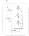
本実施形態では、風力発電施設28の複数基の風力発電装置が全て本発明に第1〜第5の実施形態のいずれかに係る風力発電装置1であり、これら複数基の風力発電装置1-1〜1-4のうち、最も風上側に位置している1つの風力発電装置1-1が取得した風向風速の情報を他の風力発電機1-2〜1-4が利用する構成としている。
[Seventh Embodiment]
A wind power generation facility operation control method according to the seventh embodiment will be described with reference to FIG.
In the present embodiment, all of the plurality of wind power generators of the wind power generation facility 28 are the wind power generators 1 according to any one of the first to fifth embodiments of the present invention. It is set as the structure which the other wind power generators 1-2 to 1-4 use the information of the wind direction wind speed which one wind power generator 1-1 located in the most windward among 1-4 has used. .

図11に示すように、複数の風力発電装置のうち最も風上にある風力発電機を1-1とすると、風力発電装置1-1は自装置の第1の圧力測定部16及び第2の圧力測定部17により測定した圧力測定値に基づいて得られた風向風速の情報(風向風速データD)を、風下側にある他の風力発電装置1-2〜1-4に送信する。   As shown in FIG. 11, when the wind power generator that is the most upwind among the plurality of wind power generators is defined as 1-1, the wind power generator 1-1 includes the first pressure measuring unit 16 and the second one of its own device. Information on the wind direction and wind speed (wind direction wind speed data D) obtained based on the pressure measurement value measured by the pressure measurement unit 17 is transmitted to the other wind turbine generators 1-2 to 1-4 on the leeward side.

風力発電装置1-2〜1-4は、最も風上側に位置している風力発電装置1-1から風向風速データDを受信する機能と、その受信した風向風速データDに基づいて自装置のヨー角等を制御する機能と、を有する。   The wind power generators 1-2 to 1-4 receive the wind direction wind speed data D from the wind power generator 1-1 located on the most windward side and the wind direction wind speed data D received from the wind power generator 1-2. And a function of controlling the yaw angle and the like.

なお、風力発電施設28に対する風向の変化により、風力発電施設28内において最も風上側に位置する風力発電装置は変化することになる。その場合、新たに最も風上側に位置することになった一の風力発電装置が風力発電装置1−1となり、その他の複数の風力発電装置が風力発電装置1-2〜1-4となる。   Note that the wind power generator located on the windward side in the wind power generation facility 28 changes due to a change in the wind direction with respect to the wind power generation facility 28. In that case, one wind power generator newly positioned on the windward side is the wind power generator 1-1, and the other plurality of wind power generators are the wind power generators 1-2 to 1-4.

第7の実施形態によれば、ある時刻において、風力発電施設28内の最も風上側に位置している風力発電装置1-1を特定し、当該風力発電装置1-1において得られた風向風速の情報に基づいて、風下側にある風力発電施設28内の全ての風力発電装置1-1〜1-4のナセル4のヨー角等を制御することができる。風力発電装置1-1により得られる風向風速の情報は、ブレード2の回転に伴う後流の影響を受けていない情報であるため、その情報に基づいて風力発電施設28内の全ての風力発電装置1-1〜1-4のナセル4のヨー角を制御することにより、風力発電施設28内の全ての風力発電装置1-1〜1-4において、風のエネルギーを効率良くロータの回転エネルギーに変換し得るように運転制御を行うことができる。   According to the seventh embodiment, at a certain time, the wind power generation device 1-1 that is located on the most windward side in the wind power generation facility 28 is specified, and the wind direction wind speed obtained in the wind power generation device 1-1 is determined. Based on this information, the yaw angles and the like of the nacelles 4 of all the wind power generators 1-1 to 1-4 in the wind power generation facility 28 on the leeward side can be controlled. Since the information on the wind direction and wind speed obtained by the wind power generator 1-1 is information that is not affected by the wake accompanying the rotation of the blade 2, all the wind power generators in the wind power generation facility 28 are based on the information. By controlling the yaw angle of the nacelle 4 of 1-1 to 1-4, the wind energy is efficiently converted into the rotational energy of the rotor in all the wind power generators 1-1 to 1-4 in the wind power generation facility 28. Operation control can be performed so that conversion is possible.

また、最も風上側に位置している風力発電装置1-1から風向風速の情報を受ける他の風力発電装置1-2〜1-4は、自装置に対する風向風速の急な変化を事前に把握できるため、ロータ3を停止させたり回転速度を減じたりする予防保全制御を早期に行うことが可能となり、故障や破損のリスクを軽減できる。   In addition, the other wind turbine generators 1-2 to 1-4 that receive the wind direction and wind speed information from the wind turbine generator 1-1 located on the most windward side grasp in advance a sudden change in the wind direction and wind velocity with respect to the wind turbine. Therefore, the preventive maintenance control for stopping the rotor 3 or reducing the rotation speed can be performed at an early stage, and the risk of failure or breakage can be reduced.

また、最も風上側に位置している風力発電装置1-1から風向風速の情報を受ける他の風力発電装置1-2〜1-4は、自装置の第1の圧力測定部16及び第2の圧力測定部17による圧力測定処理及びその測定値に基づく風向風速の情報の取得処理を停止しており、それらの処理が省略される分だけ自装置における情報処理量が削減されるので、情報処理の効率化及び予防保全制御の高速化を図ることが可能となる。   Further, the other wind power generators 1-2 to 1-4 receiving the wind direction and wind speed information from the wind power generator 1-1 located on the furthest wind side are the first pressure measuring unit 16 and the second of the own wind power generator 1-2. Since the pressure measurement process by the pressure measurement unit 17 and the acquisition process of the information on the wind direction and the wind speed based on the measurement value are stopped, the information processing amount in the own apparatus is reduced by the amount of the process being omitted. It becomes possible to increase the efficiency of processing and the speed of preventive maintenance control.

(変形例3)
本変形例3では、複数の風力発電装置のうち、風上側にある風力発電装置と風向きに沿ってその背後に位置する風下側の風力発電装置を特定して、ペアを形成し、風上側の風力発電装置で得た風向風速の情報を風下側の風力発電装置が利用することを特徴としている。
(Modification 3)
In the third modification, among the plurality of wind turbine generators, the wind turbine generator on the windward side and the wind turbine generator on the leeward side located behind it along the wind direction are identified, a pair is formed, and the wind turbine generator on the windward side is formed. It is characterized in that the wind power generator on the leeward side uses information on the wind direction and wind speed obtained by the wind power generator.

以下、具体例を図12を用いて説明する。
図12の例では、風力発電施設29内の複数(この例では6基)の風力発電装置1-1〜1-6のうち、1-1と1-4、1-2と1-5、及び1-3と1-6の風力発電装置が、それぞれ風向に対して風上風下関係にあり、3つの装置ペアP1〜P3が形成されている。
A specific example will be described below with reference to FIG.
In the example of FIG. 12, among a plurality (six in this example) of wind power generators 1-1 to 1-6 in the wind power generation facility 29, 1-1 and 1-4, 1-2 and 1-5, The wind power generators 1-3 and 1-6 have an upwind / downwind relationship with respect to the wind direction, and three device pairs P1 to P3 are formed.

風上側に位置する風力発電装置1-1,1-2,1-3は、自装置の第1の圧力測定部16及び第2の圧力測定部17により測定した圧力測定値に基づいて得られた風向風速データDを、それぞれ風下側に位置する風力発電装置1-4,1-5,1-6に送信する機能を有している。   The wind turbine generators 1-1, 1-2, and 1-3 located on the windward side are obtained based on the pressure measurement values measured by the first pressure measurement unit 16 and the second pressure measurement unit 17 of the own device. The wind direction wind speed data D is transmitted to the wind power generators 1-4, 1-5, and 1-6 located on the leeward side.

本変形例3によれば、風力発電施設29内において風上側の風力発電装置1-1,1-2,1-3それぞれの風下側に位置している風力発電装置1-4,1-5,1-6の制御をそれぞれの風上側に位置する風力発電装置1-1,1-2,1-3の情報に基づいて実施することができるので、場所によって風向風速が異なる風力発電施設28内の風力発電装置において、風のエネルギーをより高効率かつ高精度でロータの回転エネルギーに変換し得るように運転制御を行うことができる。   According to the third modification, in the wind power generation facility 29, the wind power generators 1-4, 1-5 located on the leeward side of the wind power generators 1-1, 1-2, 1-3 on the leeward side, respectively. , 1-6 can be implemented based on the information of the wind power generators 1-1, 1-2, 1-3 located on the windward side of the wind power generation facility 28 with different wind directions and wind speeds depending on the location. In the wind power generator, the operation control can be performed so that the wind energy can be converted into the rotational energy of the rotor with higher efficiency and higher accuracy.

また、風下側に位置する風力発電機は、自身で情報処理を行う必要がないので、風力発電施設29全体として、情報処理の効率化及び予防保全制御の高速化を図ることができる。   In addition, since the wind power generator located on the leeward side does not need to perform information processing by itself, the wind power generation facility 29 as a whole can improve the efficiency of information processing and the speed of preventive maintenance control.

[第8の実施形態]
第8の実施形態に係る風力発電施設の運転制御方法を、図13を用いて説明する。
図13に示す風力発電施設30は、複数基(この例では5基)の風力発電装置1-1〜1-5と、これらを制御する集中制御装置31と、を有している。複数基の風力発電装置1-1〜1-5には少なくとも1以上の本発明の実施形態に係る風力発電装置が含まれる。
[Eighth Embodiment]
The operation control method of the wind power generation facility which concerns on 8th Embodiment is demonstrated using FIG.
A wind power generation facility 30 shown in FIG. 13 has a plurality (five in this example) of wind power generators 1-1 to 1-5 and a central control device 31 that controls them. The plurality of wind turbine generators 1-1 to 1-5 include at least one wind turbine generator according to the embodiment of the present invention.

風力発電施設30内の全ての風力発電装置は、自装置の第1の圧力測定部16及び第2の圧力測定部17からの測定値又は風向風速計44の測定値に基づいて得られた風向風速の情報を集中制御装置31に送信する機能と、集中制御装置31から風況データを受信する機能と、集中制御装置31から受信した風況データに基づいて自装置のヨー角等を制御する機能と、を各々有する。   All wind power generators in the wind power generation facility 30 have the wind direction obtained based on the measured values from the first pressure measuring unit 16 and the second pressure measuring unit 17 of the own device or the measured values of the anemometer 44. Based on the function of transmitting wind speed information to the centralized control device 31, the function of receiving wind status data from the centralized control device 31, and the wind status data received from the centralized control device 31, the yaw angle of the own device is controlled. Each having a function.

集中制御装置31は、風力発電施設30内の全ての風力発電装置から風向風速の情報を受信する機能と、各風力発電装置から受信した風向風速の情報に基づいて、風力発電施設30内の風況を常時分析し、刻々と変化する風向風速分布を算出することで、風力発電装置の後流の影響や地形の影響などを考慮した風況データを逐次生成する機能と、生成した風況データを風力発電施設30内の全ての風力発電装置に送信する機能と、を有している。   The central control device 31 receives the wind direction wind speed information from all the wind power generation devices in the wind power generation facility 30 and the wind direction wind speed information received from each wind power generation device 30. By constantly analyzing the situation and calculating the wind direction and wind speed distribution that changes every moment, the function to sequentially generate wind condition data that takes into account the effects of the wake of the wind turbine and the topography, and the generated wind condition data For transmitting to all wind power generators in the wind power generation facility 30.

第8の実施形態によれば、風力発電施設30内の全ての風力発電装置における風向風速の情報を集中制御装置31に集約し、その集約した情報に基づいて、風力発電施設30内の全ての風力発電装置のヨー角等を制御することができる。よって、風力発電施設30全体としての風のエネルギーの利用効率を最大化しうるように、風力発電施設30内の全ての風力発電装置を運転制御することができる。   According to the eighth embodiment, the information on the wind direction and wind speed in all the wind power generation devices in the wind power generation facility 30 is collected in the central control device 31, and all of the wind power generation facilities 30 in the wind power generation facility 30 are collected based on the collected information. The yaw angle of the wind power generator can be controlled. Therefore, it is possible to control the operation of all the wind power generators in the wind power generation facility 30 so as to maximize the use efficiency of wind energy as the entire wind power generation facility 30.

以上、本発明のいくつかの実施形態を説明したが、これらの実施形態は、例として提示したものであり、発明の範囲を限定することは意図していない。これら新規な実施形態は、その他の様々な形態で実施されることが可能であり、発明の要旨を逸脱しない範囲で、種々の省略、組み合わせ、置き換え、変更を行うことができる。これら実施形態やその変形は、発明の範囲や要旨に含まれるとともに、特許請求の範囲に記載された発明とその均等の範囲に含まれる。   As mentioned above, although some embodiment of this invention was described, these embodiment is shown as an example and is not intending limiting the range of invention. These novel embodiments can be implemented in various other forms, and various omissions, combinations, replacements, and changes can be made without departing from the scope of the invention. These embodiments and modifications thereof are included in the scope and gist of the invention, and are included in the invention described in the claims and the equivalents thereof.

例えば、上記第1の実施形態において、通常時には、第1の圧力測定部16及び第2の圧力測定部17による測定値に基づいて運転制御を実施し、第1の圧力測定部16又は第2の圧力測定部17に故障などが発生した異常時には、風向風速計15による測定値に基づいて運転制御を実施するようにしてもよい。その他の実施形態についても同様である。   For example, in the first embodiment, in the normal time, the operation control is performed based on the measurement values obtained by the first pressure measurement unit 16 and the second pressure measurement unit 17, and the first pressure measurement unit 16 or the second pressure measurement unit 16 is operated. When an abnormality occurs in the pressure measuring unit 17, the operation control may be performed based on the measured value by the anemometer 15. The same applies to other embodiments.

また、上記第1の実施形態に係る風力発電装置1では、第1の圧力測定部16及び第2の圧力測定部17の測定値に基づく風向風速により、ナセル4のヨー制御がなされるとともにブレード2のピッチ角制御がなされる構成としたが、ブレード2のピッチ角制御については、従来と同様に、ナセル4の上部に設置された風向風速計15により測定した風向風速のみに基づいてなされるようにしてもよい。その他の実施形態についても同様である。   Further, in the wind turbine generator 1 according to the first embodiment, yaw control of the nacelle 4 is performed by the wind direction and wind speed based on the measurement values of the first pressure measurement unit 16 and the second pressure measurement unit 17, and the blade Although the pitch angle control of the blade 2 is performed, the pitch angle control of the blade 2 is performed based on only the wind direction wind speed measured by the wind direction anemometer 15 installed on the upper part of the nacelle 4 as in the conventional case. You may do it. The same applies to other embodiments.

また、上記第1の実施形態に係る風力発電装置1において、チルト角θを変化させるチルト駆動部を更に備え、第1の圧力測定部16及び第2の圧力測定部17による圧力測定値に基づいてチルト駆動部を制御するように構成してもよい。その他の実施形態についても同様である。   The wind turbine generator 1 according to the first embodiment further includes a tilt driving unit that changes the tilt angle θ, and is based on pressure measurement values obtained by the first pressure measurement unit 16 and the second pressure measurement unit 17. The tilt drive unit may be controlled. The same applies to other embodiments.

また、図9に示した変形例2では、第1の圧力測定部16及び第2の圧力測定部17のそれぞれの圧力導通管18内に粘着性の流体23が充填され、それぞれの圧力導通管18の外部側の端部18bが弾性変形可能な封止体25で封止されているが、この構成において流体23を省略することも可能である。すなわち、圧力導通管18の外部側の端部18bを弾性変形可能な封止体25で気密に封止することにより、圧力導通管18の内部に空気が閉じ込められた状態にしておき、外気圧が封止体25及び圧力導通管18内の空気を介して感圧素子19に作用するように構成することも可能である。この構成によっても、雨水や砂塵などから感圧素子19を有効に保護することができる。   Moreover, in the modification 2 shown in FIG. 9, the adhesive fluid 23 is filled in each pressure conduction pipe | tube 18 of the 1st pressure measurement part 16 and the 2nd pressure measurement part 17, and each pressure conduction pipe | tube is filled. Although the end 18b on the outer side of 18 is sealed with an elastically deformable sealing body 25, the fluid 23 may be omitted in this configuration. That is, the outer end 18b of the pressure conducting tube 18 is hermetically sealed with the elastically deformable sealing body 25 so that air is trapped inside the pressure conducting tube 18, and the external pressure Can be configured to act on the pressure-sensitive element 19 via the air in the sealing body 25 and the pressure conducting pipe 18. Also with this configuration, the pressure sensitive element 19 can be effectively protected from rainwater, dust, and the like.

1…風力発電装置、1−1〜1-6…風力発電装置、2…ブレード、3…ロータ、4…ナセル、5…タワー、6…ヨー駆動部、7…設置面、8…ハブ、9…主軸、11…ノーズコーン(略円錐状の先端部材)、12…ピッチ駆動部、14…制御部、16…第1の圧力測定部、17…第2の圧力測定部、17-1〜17-4…第2の圧力測定部、18…圧力導通管、18a…端部、18b…端部、19…感圧素子、21…温度センサ、23…流体、25…封止体、26〜30…風力発電施設、A…ロータ軸、D…風向風速データ、G1…上流側装置群、G2…下流側装置群 DESCRIPTION OF SYMBOLS 1 ... Wind power generator, 1-1 to 1-6 ... Wind power generator, 2 ... Blade, 3 ... Rotor, 4 ... Nacelle, 5 ... Tower, 6 ... Yaw drive part, 7 ... Installation surface, 8 ... Hub, 9 DESCRIPTION OF SYMBOLS ... Main axis, 11 ... Nose cone (substantially conical tip member), 12 ... Pitch drive part, 14 ... Control part, 16 ... 1st pressure measurement part, 17 ... 2nd pressure measurement part, 17-1-17 -4 ... second pressure measuring unit, 18 ... pressure conducting tube, 18a ... end, 18b ... end, 19 ... pressure sensor, 21 ... temperature sensor, 23 ... fluid, 25 ... sealed body, 26-30 ... wind power generation facility, A ... rotor shaft, D ... wind direction wind speed data, G1 ... upstream device group, G2 ... downstream device group

Claims (10)

ブレードを放射状に支持するハブと、当該ハブの一端部に固定されたノーズコーンと、を有するロータと、
前記ロータをロータ軸回りに回転可能に支持するナセルと、
前記ナセルの方向を制御するための制御部と、
前記ノーズコーンの先端部及び周面部にそれぞれ設けられた第1の圧力測定部及び第2の圧力測定部と、
を有することを特徴とする風力発電装置。
A rotor having a hub that radially supports the blades, and a nose cone fixed to one end of the hub;
A nacelle that rotatably supports the rotor around a rotor axis;
A control unit for controlling the direction of the nacelle;
A first pressure measurement unit and a second pressure measurement unit respectively provided at a tip portion and a peripheral surface portion of the nose cone;
A wind power generator characterized by comprising:
前記第2の圧力測定部は、前記ロータの回転軸に関して180度で回転対称となる二か所に設けられていることを特徴とする請求項1記載の風力発電装置。   2. The wind power generator according to claim 1, wherein the second pressure measurement unit is provided at two positions that are rotationally symmetric at 180 degrees with respect to a rotation axis of the rotor. 前記第2の圧力測定部は、前記ロータの回転軸に関して90度で回転対称となる四か所に設けられていることを特徴とする請求項1記載の風力発電装置。   2. The wind power generator according to claim 1, wherein the second pressure measurement unit is provided at four locations that are rotationally symmetric at 90 degrees with respect to the rotation axis of the rotor. 前記第1の圧力測定部及び前記第2の圧力測定部は、
前記ノーズコーンの外部に開口する圧力導通管と、
前記圧力導通管の端部に設けられた感圧素子と、を有することを特徴とする請求項1乃至3のいずれか1項記載の風力発電装置。
The first pressure measuring unit and the second pressure measuring unit are:
A pressure conducting tube that opens to the outside of the nose cone;
The wind power generator according to any one of claims 1 to 3, further comprising a pressure-sensitive element provided at an end of the pressure conducting pipe.
前記第1の圧力測定部及び前記第2の圧力測定部の近傍に温度センサを設けたことを特徴とする請求項4記載の風力発電装置。   The wind power generator according to claim 4, wherein a temperature sensor is provided in the vicinity of the first pressure measurement unit and the second pressure measurement unit. 前記圧力導通管内に粘着性の流体が充填されていることを特徴とする請求項4又は5記載の風力発電装置。   The wind power generator according to claim 4 or 5, wherein the pressure conducting pipe is filled with an adhesive fluid. 前記圧力導通管の開口に弾性変形可能な封止体が設けられていることを特徴とする請求項6記載の風力発電装置。   The wind power generator according to claim 6, wherein a sealing body that is elastically deformable is provided at an opening of the pressure conducting pipe. 請求項1乃至7のいずれかに記載の風力発電装置を少なくとも1以上有する風力発電施設の運転制御方法であって、
前記風力発電装置に設けられた第1の圧力測定部及び第2の圧力測定部で測定された風向風速データに基づいて、前記風力発電施設の全ての風力発電装置の運転を制御することを特徴とする風力発電施設の運転制御方法。
An operation control method for a wind power generation facility having at least one or more wind power generators according to any one of claims 1 to 7,
Based on the wind direction wind speed data measured by the first pressure measuring unit and the second pressure measuring unit provided in the wind power generator, the operation of all the wind power generators of the wind power generation facility is controlled. An operation control method for a wind power generation facility.
請求項1乃至7のいずれかに記載の風力発電装置を複数備えた風力発電施設の運転制御方法であって、
前記複数の風力発電装置のうち、最も風上側に位置している風力発電装置を特定し、その風力発電装置で得られた風向風速データに基づいて、前記風力発電施設の全ての風力発電装置の運転を制御することを特徴とする風力発電施設の運転制御方法。
A wind power generation facility operation control method comprising a plurality of wind turbine generators according to any one of claims 1 to 7,
Of the plurality of wind turbine generators, identify the wind turbine generator located on the most windward side, and based on the wind direction wind speed data obtained by the wind turbine generator, all the wind turbine generators of the wind turbine generator facility An operation control method for a wind power generation facility, characterized by controlling operation.
請求項1乃至7のいずれかに記載の風力発電装置を複数備えた風力発電施設の運転制御方法であって、
前記複数の風力発電装置のうち、風向きに対し風上側に位置している風力発電装置と風下側にある風力発電装置を特定し、風上側に位置している風力発電装置で得られた風向風速データを用いて風下側にある風力発電装置の運転を制御することを特徴とする風力発電施設の運転制御方法。
A wind power generation facility operation control method comprising a plurality of wind turbine generators according to any one of claims 1 to 7,
Of the plurality of wind turbine generators, the wind turbine generator located on the windward side with respect to the wind direction and the wind turbine generator on the leeward side are specified, and the wind direction wind speed obtained by the wind turbine generator located on the windward side An operation control method for a wind power generation facility, wherein operation of a wind power generator on the leeward side is controlled using data.
JP2017016683A 2017-02-01 2017-02-01 Wind power generator and operation control method of wind power generating facility Pending JP2018123762A (en)

Priority Applications (1)

Application Number Priority Date Filing Date Title
JP2017016683A JP2018123762A (en) 2017-02-01 2017-02-01 Wind power generator and operation control method of wind power generating facility

Applications Claiming Priority (1)

Application Number Priority Date Filing Date Title
JP2017016683A JP2018123762A (en) 2017-02-01 2017-02-01 Wind power generator and operation control method of wind power generating facility

Publications (1)

Publication Number Publication Date
JP2018123762A true JP2018123762A (en) 2018-08-09

Family

ID=63109463

Family Applications (1)

Application Number Title Priority Date Filing Date
JP2017016683A Pending JP2018123762A (en) 2017-02-01 2017-02-01 Wind power generator and operation control method of wind power generating facility

Country Status (1)

Country Link
JP (1) JP2018123762A (en)

Cited By (2)

* Cited by examiner, † Cited by third party
Publication number Priority date Publication date Assignee Title
CN111779627A (en) * 2020-06-24 2020-10-16 国电电力浙江舟山海上风电开发有限公司 Impeller control system with anti-typhoon mode for offshore wind farms
CN113740559A (en) * 2020-05-15 2021-12-03 新疆金风科技股份有限公司 Wind measuring system, wind generating set and wind measuring method

Cited By (2)

* Cited by examiner, † Cited by third party
Publication number Priority date Publication date Assignee Title
CN113740559A (en) * 2020-05-15 2021-12-03 新疆金风科技股份有限公司 Wind measuring system, wind generating set and wind measuring method
CN111779627A (en) * 2020-06-24 2020-10-16 国电电力浙江舟山海上风电开发有限公司 Impeller control system with anti-typhoon mode for offshore wind farms

Similar Documents

Publication Publication Date Title
ES2551873T3 (en) Apparatus for evaluating sensors and / or for controlling the operation of an apparatus that includes a sensor
US8198741B2 (en) Wind turbine generator system including controller that performs cut-out control
US20120128488A1 (en) Rotor-sector based control of wind turbines
EP2889472B1 (en) Wind farm, control method thereof and wind power generation unit
US8177505B2 (en) Method for measuring a rotational position of a rotor blade of a wind turbine and measuring device
US8231344B2 (en) Methods for controlling the amplitude modulation of noise generated by wind turbines
DK180689B1 (en) Device for determining the distance between a wind turbine blade and its wind turbine tower at each passing
CN112696317B (en) System and method for controlling a wind turbine based on a collective pitch offset
US20100143128A1 (en) Wind turbine yaw bearing determination
US20100143119A1 (en) Method and apparatus for controlling acoustic emissions of a wind turbine
WO2011150942A1 (en) An improved wind turbine doppler anemometer
EP2607689B1 (en) Rotor-sector based control of wind turbines
DK178811B1 (en) Methods and systems for reducing amplitude modulation in wind turbines
CN102141004A (en) System and method for monitoring and controlling wind turbine blade deflection
EP3232051A1 (en) Method and device for loading detection of blade of wind power turbine
WO2015124946A1 (en) Method and system for improving energy capture efficiency from an energy capture device
ES2899153T3 (en) System and procedure to protect wind turbines from extreme loads and fatigue
JP6258339B2 (en) Wind turbine device, wind turbine device abnormality detection device, and wind turbine device abnormality detection method
KR101656478B1 (en) Wind turbine generator
ES2763074T3 (en) Control for a wind turbine
JP2018123762A (en) Wind power generator and operation control method of wind power generating facility
CN108691727B (en) Wind turbine guide sleeve
US9920744B2 (en) System and method for detecting rotor asymmetry
CN107429663A (en) The control of wind turbine
CN113740559A (en) Wind measuring system, wind generating set and wind measuring method

Legal Events

Date Code Title Description
A711 Notification of change in applicant

Free format text: JAPANESE INTERMEDIATE CODE: A712

Effective date: 20171122

A711 Notification of change in applicant

Free format text: JAPANESE INTERMEDIATE CODE: A711

Effective date: 20171127