JP2018123774A - Filter device - Google Patents
Filter device Download PDFInfo
- Publication number
- JP2018123774A JP2018123774A JP2017017084A JP2017017084A JP2018123774A JP 2018123774 A JP2018123774 A JP 2018123774A JP 2017017084 A JP2017017084 A JP 2017017084A JP 2017017084 A JP2017017084 A JP 2017017084A JP 2018123774 A JP2018123774 A JP 2018123774A
- Authority
- JP
- Japan
- Prior art keywords
- filter device
- gas
- compression
- introduction holes
- compression chamber
- Prior art date
- Legal status (The legal status is an assumption and is not a legal conclusion. Google has not performed a legal analysis and makes no representation as to the accuracy of the status listed.)
- Pending
Links
- 230000006835 compression Effects 0.000 claims abstract description 70
- 238000007906 compression Methods 0.000 claims abstract description 70
- 238000005192 partition Methods 0.000 claims abstract description 25
- 230000007423 decrease Effects 0.000 claims description 4
- 238000007599 discharging Methods 0.000 claims description 3
- 238000005265 energy consumption Methods 0.000 abstract description 6
- 239000007789 gas Substances 0.000 description 65
- 238000011144 upstream manufacturing Methods 0.000 description 3
- 238000009423 ventilation Methods 0.000 description 3
- 238000000746 purification Methods 0.000 description 2
- 239000006185 dispersion Substances 0.000 description 1
- 239000000463 material Substances 0.000 description 1
- 230000004048 modification Effects 0.000 description 1
- 238000012986 modification Methods 0.000 description 1
- 239000000126 substance Substances 0.000 description 1
Images

Classifications
-
- F—MECHANICAL ENGINEERING; LIGHTING; HEATING; WEAPONS; BLASTING
- F04—POSITIVE - DISPLACEMENT MACHINES FOR LIQUIDS; PUMPS FOR LIQUIDS OR ELASTIC FLUIDS
- F04B—POSITIVE-DISPLACEMENT MACHINES FOR LIQUIDS; PUMPS
- F04B39/00—Component parts, details, or accessories, of pumps or pumping systems specially adapted for elastic fluids, not otherwise provided for in, or of interest apart from, groups F04B25/00 - F04B37/00
- F04B39/16—Filtration; Moisture separation
Landscapes
- Engineering & Computer Science (AREA)
- Mechanical Engineering (AREA)
- General Engineering & Computer Science (AREA)
- Compressor (AREA)
- Structures Of Non-Positive Displacement Pumps (AREA)
Abstract
Description
本開示は、気体圧縮機の吸気ポートに取り付け可能なフィルタ装置に関する。 The present disclosure relates to a filter device attachable to an intake port of a gas compressor.
気体圧縮機では、圧縮対象となる気体を取り込む吸入口に、気体に含まれる異物等を除去するために浄化用のフィルタ装置が設けられることがある。このようなフィルタ装置では、気体圧縮機の吸気ポートに取り付けられる出口側が負圧になると、入口側から気体が吸入される。吸入された気体は、フィルタ装置の内部に収容されたフィルタエレメントを通過することにより浄化され、出口側から気体圧縮機の吸気ポートに供給される。 In a gas compressor, a filter device for purification may be provided at an inlet port that takes in a gas to be compressed in order to remove foreign substances contained in the gas. In such a filter device, when the outlet side attached to the intake port of the gas compressor has a negative pressure, gas is sucked from the inlet side. The sucked gas is purified by passing through a filter element housed inside the filter device, and is supplied from the outlet side to the intake port of the gas compressor.
この種の気体圧縮機に用いられるフィルタ装置の一例として、特許文献1がある。この文献では、気体圧縮機の吸入口に接続されるフィルタ装置であって、フィルタエレメント(瀘材)の一部が目詰まり等して使用に不適切となった場合に、当該不適切になった部分のみを交換することで、長期に亘り、経済的かつ安定した運転を行いうるようにしたフィルタ装置が開示されている。
There exists
ところで、吸気ポートにフィルタ装置が取り付けられた気体圧縮機では、フィルタエレメントの通気抵抗や、フィルタエレメントを収容するケーシングの壁面との摩擦等により、少なからず圧力損失が生じる。そのため、吸気ポートにフィルタ装置を設置しない場合に比べて、少なからず導入圧力が低下してしまい、その結果、気体圧縮機の体積効率の低下や消費エネルギの増大を招く要因となっている。 By the way, in the gas compressor in which the filter device is attached to the intake port, pressure loss is not a little caused by the ventilation resistance of the filter element, the friction with the wall surface of the casing housing the filter element, and the like. For this reason, compared with the case where the filter device is not installed in the intake port, the introduction pressure is reduced to a great extent, resulting in a decrease in volumetric efficiency and an increase in energy consumption of the gas compressor.
本発明の少なくとも一実施形態は上述の事情に鑑みなされたものであり、気体圧縮機の吸気ポートに取り付けられた際に、良好な体積効率を実現することで気体圧縮機の単位気体量当たりの消費エネルギを低減可能なフィルタ装置を提供することを目的とする。 At least one embodiment of the present invention has been made in view of the above circumstances, and when mounted on an intake port of a gas compressor, it achieves a good volumetric efficiency so as to achieve per unit gas amount of the gas compressor. It aims at providing the filter apparatus which can reduce energy consumption.
(1)本発明の少なくとも一実施形態に係るフィルタ装置は上記課題を解決するために、気体圧縮機の吸気ポートに取り付け可能なフィルタ装置であって、前記気体を浄化するためのフィルタエレメントと、前記フィルタエレメントを収容する収容部を有するケーシングと、前記収容部に前記気体を導入するための入口部と、圧縮室を有し、前記フィルタエレメントを通過した前記気体を吐出するための出口部と、前記収容部と前記圧縮室とを隔離する隔壁に、前記圧縮室に設定された圧縮領域に向けて開口するように設けられた複数の導入孔と、を備える。 (1) A filter device according to at least one embodiment of the present invention is a filter device that can be attached to an intake port of a gas compressor in order to solve the above-described problem, and a filter element for purifying the gas; A casing having a housing portion for housing the filter element, an inlet portion for introducing the gas into the housing portion, an outlet portion for discharging the gas having a compression chamber and having passed through the filter element; And a plurality of introduction holes provided in the partition wall that separates the housing portion and the compression chamber so as to open toward a compression region set in the compression chamber.
上記(1)の構成によれば、複数の導入孔の各々から噴出される気体は、圧縮領域にて互いに衝突する。すると、噴流が有する運動エネルギが圧力エネルギに変換され、気体の圧縮がなされるため、フィルタ装置を通過した気体の圧力が向上する。その結果、気体がフィルタ装置を通過する際に、フィルタエレメントの通気抵抗やフィルタエレメントを収容するケーシングの壁面との摩擦等により受ける圧力損失を軽減し、更には、フィルタ装置を通過した気体の圧力を積極的に向上できる。このようにして、気体圧縮機の吸気ポートに取り付けられた際に、良好な体積効率を実現することで気体圧縮機の単位気体量当たりの消費エネルギを低減できる。 According to the configuration of (1) above, the gas ejected from each of the plurality of introduction holes collides with each other in the compression region. Then, the kinetic energy of the jet is converted into pressure energy, and the gas is compressed, so that the pressure of the gas that has passed through the filter device is improved. As a result, when the gas passes through the filter device, the pressure loss caused by the ventilation resistance of the filter element and the friction with the wall surface of the casing housing the filter element is reduced, and further, the pressure of the gas passing through the filter device is reduced. Can be improved positively. In this way, when attached to the intake port of the gas compressor, energy consumption per unit gas amount of the gas compressor can be reduced by realizing good volumetric efficiency.
(2)幾つかの実施形態では、上記(1)の構成において、前記圧縮領域は、前記隔壁において前記複数の導入孔が設けられた領域より狭く設定される。 (2) In some embodiments, in the configuration of (1), the compression region is set narrower than a region where the plurality of introduction holes are provided in the partition wall.
上記(2)の構成によれば、そのため、フィルタエレメントを通過した気体は、複数の導入孔から圧縮領域に向けて吹き出された際に、圧縮領域にて噴流として互いに局所的に衝突し、衝突圧縮が効果的になされる。 According to the configuration of (2) above, when the gas that has passed through the filter element is blown out from the plurality of introduction holes toward the compression region, the gas locally collides with each other as a jet in the compression region. Compression is done effectively.
(3)幾つかの実施形態では、上記(1)又は(2)の構成において、前記複数の導入孔は、前記圧縮領域の中心軸に対して同心状に配列されている。 (3) In some embodiments, in the configuration of (1) or (2), the plurality of introduction holes are arranged concentrically with respect to the central axis of the compression region.
上記(3)の構成によれば、複数の導入孔が圧縮領域の中心軸に対して同心状に設けられるため、複数の導入孔から噴出される噴流同士は、圧縮領域にて局所的に衝突する。これにより、圧縮領域では、より効果的に衝突圧縮がなされ、フィルタ装置を通過した気体の圧力をより増加させることができる。 According to the configuration of (3) above, since the plurality of introduction holes are provided concentrically with the central axis of the compression region, the jets ejected from the plurality of introduction holes collide locally in the compression region. To do. Thereby, in a compression area | region, collision compression is made more effectively and the pressure of the gas which passed the filter apparatus can be made to increase more.
(4)幾つかの実施形態では、上記(3)の構成において、前記複数の導入孔は、前記中心軸に対して周方向及び径方向に沿って配列されている。 (4) In some embodiments, in the configuration of (3), the plurality of introduction holes are arranged along a circumferential direction and a radial direction with respect to the central axis.
上記(4)の構成によれば、隔壁に形成される複数の導入孔を、中心軸に対して周方向及び径方向に配列することで、限られた範囲に多数の導入孔を設けることができる。これにより、多くの噴流を圧縮領域にて衝突させ、フィルタ装置を通過した気体の圧力をより効果的に増加できる。 According to the configuration of (4) above, a plurality of introduction holes can be provided in a limited range by arranging a plurality of introduction holes formed in the partition wall in the circumferential direction and the radial direction with respect to the central axis. it can. Thereby, many jets collide in a compression area | region, and the pressure of the gas which passed the filter apparatus can be increased more effectively.
(5)幾つかの実施形態では、上記(4)の構成において、前記複数の導入孔は、径方向の内側から外側にかけて開口径が小さくなるように形成されている。 (5) In some embodiments, in the configuration of (4), the plurality of introduction holes are formed so that the opening diameter decreases from the inner side to the outer side in the radial direction.
径方向外側の導入孔は径方向内側の導入孔に比べて圧縮領域までの距離が長くなるため、圧縮領域への到達時における噴流が弱くなりがちである。そこで上記(5)の構成では、径方向外側の導入孔の開口径を小さくすることで、導入孔からの吹き出しを強化し、圧縮領域における各導入孔からの噴流のバラツキを抑えることで、噴流同士の衝突圧縮をより効果的に行うことができる。 Since the introduction hole on the radially outer side has a longer distance to the compression region than the introduction hole on the radially inner side, the jet flow when reaching the compression region tends to be weak. Therefore, in the configuration of (5) above, by reducing the diameter of the introduction hole on the radially outer side, the blowout from the introduction hole is strengthened, and the variation in the jet flow from each introduction hole in the compression region is suppressed. The collision compression between each other can be performed more effectively.
(6)幾つかの実施形態では、上記(1)から(5)のいずれか一構成において、前記圧縮室は前記収容部より小さい容積を有する。 (6) In some embodiments, in any one of the configurations (1) to (5), the compression chamber has a volume smaller than that of the housing portion.
上記(6)の構成によれば、複数の導入孔からの噴流によって衝突圧縮が行われる圧縮室が、導入もととなる収容部より小さい容積を有するように形成される。これにより、圧縮室で衝突圧縮により圧力が上昇した気体が分散することが抑制され、フィルタ装置から高い圧力が確保された気体を供給できる。 According to the configuration of (6) above, the compression chamber in which the collision compression is performed by the jets from the plurality of introduction holes is formed so as to have a smaller volume than the accommodating portion as the introduction source. Thereby, it is possible to suppress the gas whose pressure has been increased by the collision compression in the compression chamber from being dispersed, and to supply the gas whose high pressure is secured from the filter device.
(7)幾つかの実施形態では、上記(1)から(6)のいずれか一項に記載の構成において、前記隔壁は前記ケーシングの一部によって構成されており、前記圧縮室は、前記隔壁に対して下流側から取り付けられる出口側部材によって規定される。 (7) In some embodiments, in the configuration according to any one of (1) to (6), the partition is configured by a part of the casing, and the compression chamber is the partition Is defined by the outlet side member attached from the downstream side.
上記(7)の構成によれば、ケーシングに対して出口側部材が組み付けられることで、圧縮室が構成される。このようにして簡易な構成で上記構成を有するフィルタ装置を実現できる。尚、これは全体を一体的に構成することを妨げるものではない。 According to the configuration of (7) above, the compression chamber is configured by assembling the outlet side member to the casing. In this way, a filter device having the above configuration can be realized with a simple configuration. Note that this does not prevent the entire structure from being integrated.
(8)幾つかの実施形態では、上記(7)に記載の構成において、前記出口側部材は、前記隔壁とともに前記圧縮室を規定する第1部分と、前記第1部分の下流側に設けられ、前記吸気ポートに対して取り付け可能な第2部分と、を含み、前記第2部分は前記第1部分より小さな容積を有する。 (8) In some embodiments, in the configuration described in (7) above, the outlet side member is provided on the downstream side of the first portion that defines the compression chamber together with the partition, and on the downstream side of the first portion. A second part attachable to the intake port, the second part having a smaller volume than the first part.
上記(8)の構成によれば、出口側部材20は第1部分及び第2部分の2段構成を有しており、特に、第2部分が第1部分に比べて更に小さい容積を有する。これにより、圧縮室から送り出される気体が分散することが更に抑制され、フィルタ装置からより圧力損失の少ない気体を供給できるようになっている。
According to the configuration of (8) above, the
本発明の少なくとも一実施形態によれば、気体圧縮機の吸気ポートに取り付けられた際に、良好な体積効率を実現することで気体圧縮機の単位気体量当たりの消費エネルギを低減可能なフィルタ装置を提供できる。 According to at least one embodiment of the present invention, a filter device capable of reducing energy consumption per unit gas amount of a gas compressor by realizing good volumetric efficiency when attached to an intake port of the gas compressor. Can provide.
以下、添付図面を参照して本発明の幾つかの実施形態について説明する。ただし、実施形態として記載されている又は図面に示されている構成部品の寸法、材質、形状、その相対的配置等は、本発明の範囲をこれに限定する趣旨ではなく、単なる説明例にすぎない。 Hereinafter, some embodiments of the present invention will be described with reference to the accompanying drawings. However, the dimensions, materials, shapes, relative arrangements, etc. of the components described in the embodiments or shown in the drawings are not intended to limit the scope of the present invention, but are merely illustrative examples. Absent.
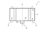
図1は本発明の少なくとも一実施形態に係るフィルタ装置1の全体構成を示す断面図である。フィルタ装置1は、気体圧縮機(不図示)に取り付けられることで、気体圧縮機の吸気ポートに供給される気体を浄化する装置である。ケーシング2は中心軸Cに沿った略円筒形状を有しており、フィルタエレメント4を収容する収容部6を有する。収容部6の上流側には、収容部6に気体を導入するための入口部8が設けられている。また収容部6の下流側には、収容部6にてフィルタエレメント4を通過した気体を吐出するための出口部10が設けられている。
FIG. 1 is a cross-sectional view showing an overall configuration of a
入口部8は略円筒形状を有するケーシング2の一方の端面上において、中心軸Cの周りを周方向に沿ってリング状に形成された開口部として形成されている。フィルタ装置1の下流側で負圧が生じると、入口部8には図1で矢印で示されるような気流が生じ、収容部6に気体が導入される。また出口部10は、ケーシング2のうち入口部8が設けられた端面に設けられており、収容部6にてフィルタエレメント4を通過した気体が、下流側に向けて排出される。
尚、このようなケーシング2における入口部8及び出口部10のレイアウトは一例に過ぎず、本発明の実施を妨げない範囲において限定されない。
The
In addition, the layout of the
収容部6はフィルタエレメント4を収容するための内部空間を有する。収容部6の内部空間のうち入口部8の下流側、且つ、出口部10の上流側にはフィルタエレメント4が配置されている。フィルタエレメント4は入口部8から取り込まれた気体を浄化するための濾材であり、中心軸Cを囲むように周方向に沿って略円筒形状を有している。これにより、入口部8からケーシング2に取り込まれた気体は、収容部6に収容されたフィルタエレメント4を通過した後、出口部10から気体圧縮機側に排出されるように構成されている。
The
出口部10は、収容部6の下流側に設けられた圧縮室12を有する。本実施形態では特に、圧縮室12は、ケーシング2の端面を構成すし、収容部6と圧縮室12とを隔離する隔壁14と、隔壁14より下流側にケーシング2とは別部材として構成された出口側部材20とによって規定されている。すなわち、隔壁14はケーシング2の一部によって構成されており、圧縮室12は、隔壁14に対して下流側から取り付けられる出口側部材20によって規定される。そして出口側部材20は、ケーシング2の一部である隔壁14とともに圧縮室12を規定する第1部分20aと、第1部分20aの下流側に設けられ、気体圧縮機の吸気ポートに対して取り付け可能な第2部分20bとを備える。第1部分20a及び第2部分20bは、それぞれ中心軸Cに沿った略円筒形状を有している。
The
第1部分20aは隔壁14とともに圧縮室12を形成する。隔壁14には、収容部6と圧縮室12とを連通するように隔壁14に形成された複数の導入孔16によって構成される。複数の導入孔16は、これらを通過する気体が噴流となるように設けられており、圧縮室12に設定された圧縮領域18に向けて開口している。圧縮領域18は、圧縮室12の一部として設定されており、特に、隔壁14において複数の導入孔16が設けられた領域より狭く設定される。そのため、フィルタエレメント4を通過した気体は、複数の導入孔16から圧縮領域18に向けて噴流として噴出し、圧縮領域18にて互いに局所的に衝突する。このようにして、衝突圧縮が効果的になされる。
The
ここで図4は従来例に係るフィルタ装置1’の全体構成を示す断面図である。尚、図4では本実施形態に係るフィルタ装置1と対応する箇所には共通の符号を付すこととし、重複する説明は適宜省略することとする。フィルタ装置1’では、入口部8から取り込まれた気体は、収容部6のフィルタエレメント4を通過する際の通気抵抗やケーシング2の壁面との摩擦等により圧力損失を生じる。
Here, FIG. 4 is a cross-sectional view showing the overall configuration of the
一方、本実施形態に係るフィルタ装置1では、複数の導入孔16から噴流として噴出される気体同士を衝突させることで圧力を上昇させることができるため、このような圧力損失を低減し、更には、フィルタ装置1の通過後の気体圧力を積極的に向上させることができる。またこのような出口部10における衝突圧縮は、図1及び図4を比較してわかるように、出口部10の上流側の構成を変更することなく行うことができるので、フィルタ装置1の浄化性能を維持しながら上記作用を得ることができる。
On the other hand, in the
また、複数の導入孔16から噴流として噴出される気体同士の衝突圧縮が行われる圧縮室12は、収容部6に比べて小さい容積を有するように形成されている。これにより、圧縮室12で衝突圧縮により圧力が上昇した気体が分散することで圧力が低下することを抑制できる。
Further, the
また出口側部材20は、第2部分20bが第1部分20aに比べて更に小径に形成されることで(第2部分20bは第1部分20aより小さな容積を有することで)、2段構造を有している。これにより、圧縮室12から送り出される気体が分散することが更に抑制され、フィルタ装置1からより圧力損失の少ない気体を供給できるようになっている。
Further, the
なお、気体同士の衝突圧縮が行われる圧縮領域18は、第2部分20bに囲まれる領域を含むように設定されることが好ましい。これにより、衝突圧縮により上昇した気体の圧力が低下することをより効果的に抑制できる。
In addition, it is preferable that the compression area |
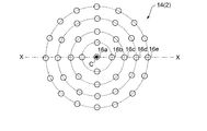
ここで図2は図1の隔壁14に設けられた複数の導入孔16の配置レイアウトを中心軸C側から示す平面図である(尚、図1は図2のX−X線断面に対応する断面を示している)。複数の導入孔16は、中心軸Cに対して同心状に設けられている。本実施形態では特に、導入孔16は、中心軸Cに対して周方向及び径方向に複数配列されており、中心軸Cから近い側から順に16a、16b、16c、16d及び16eの各グループがそれぞれ中心軸Cに対して同心状に設けられている。これにより、隔壁14の限られた範囲に多数の導入孔16を効率的に設けることができ、多数の噴流同士を狭い圧縮領域18にて局所的に衝突させることで、より高度な衝突圧縮ができるようになっている。
2 is a plan view showing an arrangement layout of the plurality of introduction holes 16 provided in the
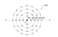
図2では各導入孔16の開口径が等しい場合が示されているが、図3のように各導入孔16の開口径が異なるように形成してもよい。図3では特に、複数の導入孔16は、径方向の内側から外側にかけて開口径が小さくなるように形成されている。径方向外側の導入孔16は径方向内側の導入孔16に比べて圧縮領域18までの距離が長くなるため、圧縮領域18への到達時における噴流が弱くなりがちである。そこで、径方向外側の導入孔16の開口径を小さくすることで、導入孔16からの吹き出しを強化し、圧縮領域18における各導入孔16から噴流として噴出される気体のバラツキを抑えることで、噴流同士の衝突圧縮をより効果的に行うことができる。
Although FIG. 2 shows a case where the opening diameters of the introduction holes 16 are equal, the opening diameters of the introduction holes 16 may be different as shown in FIG. In FIG. 3, in particular, the plurality of introduction holes 16 are formed so that the opening diameter decreases from the inner side to the outer side in the radial direction. Since the
尚、上記実施形態では、出口側部材20をケーシング2と別部材として構成した場合を例示したが、出口側部材20はケーシング2と一体的に構成されていてもよい。
In addition, in the said embodiment, although the case where the
以上説明したように本発明の少なくとも一実施形態によれば、気体圧縮機の吸気ポートに取り付けた際に、良好な体積効率を実現することで気体圧縮機の単位気体量当たりの消費エネルギを低減可能なフィルタ装置を提供できる。 As described above, according to at least one embodiment of the present invention, when mounted on the intake port of the gas compressor, the energy consumption per unit gas amount of the gas compressor is reduced by realizing good volume efficiency. A possible filter device can be provided.
本開示は、気体圧縮機の吸気ポートに取り付け可能なフィルタ装置に利用可能である。 The present disclosure can be used for a filter device that can be attached to an intake port of a gas compressor.
1 フィルタ装置
2 ケーシング
4 フィルタエレメント
6 収容部
8 入口部
10 出口部
12 圧縮室
14 隔壁
16 導入孔
18 圧縮領域
20 出口側部材
20a 第1部分
20b 第2部分
C 中心軸
DESCRIPTION OF
Claims (8)
前記気体を浄化するためのフィルタエレメントと、
前記フィルタエレメントを収容する収容部を有するケーシングと、
前記収容部に前記気体を導入するための入口部と、
圧縮室を有し、前記フィルタエレメントを通過した前記気体を吐出するための出口部と、
前記収容部と前記圧縮室とを隔離する隔壁に、前記圧縮室に設定された圧縮領域に向けて開口するように設けられた複数の導入孔と、
を備える、フィルタ装置。 A filter device attachable to an intake port of a gas compressor,
A filter element for purifying the gas;
A casing having an accommodating portion for accommodating the filter element;
An inlet portion for introducing the gas into the housing portion;
An outlet for discharging the gas having a compression chamber and passing through the filter element;
A plurality of introduction holes provided in a partition wall that separates the housing portion and the compression chamber so as to open toward a compression region set in the compression chamber;
A filter device.
前記圧縮室は、前記隔壁に対して下流側から取り付けられる出口側部材によって規定される、請求項1から6のいずれか一項に記載のフィルタ装置。 The partition is constituted by a part of the casing,
The filter device according to any one of claims 1 to 6, wherein the compression chamber is defined by an outlet side member attached to the partition wall from the downstream side.
前記隔壁とともに前記圧縮室を規定する第1部分と、
前記第1部分の下流側に設けられ、前記吸気ポートに対して取り付け可能な第2部分と、
を含み、
前記第2部分は前記第1部分より小さな容積を有する、請求項7に記載のフィルタ装置。 The outlet side member is
A first portion defining the compression chamber together with the partition;
A second portion provided downstream of the first portion and attachable to the intake port;
Including
The filter device according to claim 7, wherein the second portion has a smaller volume than the first portion.
Priority Applications (2)
| Application Number | Priority Date | Filing Date | Title |
|---|---|---|---|
| JP2017017084A JP2018123774A (en) | 2017-02-01 | 2017-02-01 | Filter device |
| PCT/JP2018/003096 WO2018143234A1 (en) | 2017-02-01 | 2018-01-31 | Filter device |
Applications Claiming Priority (1)
| Application Number | Priority Date | Filing Date | Title |
|---|---|---|---|
| JP2017017084A JP2018123774A (en) | 2017-02-01 | 2017-02-01 | Filter device |
Publications (1)
| Publication Number | Publication Date |
|---|---|
| JP2018123774A true JP2018123774A (en) | 2018-08-09 |
Family
ID=63039644
Family Applications (1)
| Application Number | Title | Priority Date | Filing Date |
|---|---|---|---|
| JP2017017084A Pending JP2018123774A (en) | 2017-02-01 | 2017-02-01 | Filter device |
Country Status (2)
| Country | Link |
|---|---|
| JP (1) | JP2018123774A (en) |
| WO (1) | WO2018143234A1 (en) |
Family Cites Families (5)
| Publication number | Priority date | Publication date | Assignee | Title |
|---|---|---|---|---|
| JPS4937883U (en) * | 1972-07-06 | 1974-04-03 | ||
| JPS5528473U (en) * | 1978-08-14 | 1980-02-23 | ||
| JPH0319534U (en) * | 1989-07-04 | 1991-02-26 | ||
| US5205849A (en) * | 1992-06-29 | 1993-04-27 | Ransburg Corporation | Air filter having a low internal pressure drop |
| JP2948176B2 (en) * | 1997-07-02 | 1999-09-13 | 株式会社うえくら | Structure of air pump inlet |
-
2017
- 2017-02-01 JP JP2017017084A patent/JP2018123774A/en active Pending
-
2018
- 2018-01-31 WO PCT/JP2018/003096 patent/WO2018143234A1/en not_active Ceased
Also Published As
| Publication number | Publication date |
|---|---|
| WO2018143234A1 (en) | 2018-08-09 |
Similar Documents
| Publication | Publication Date | Title |
|---|---|---|
| CN102985695B (en) | Multi-stage low pressure drop muffler | |
| RU2002107872A (en) | The method of atomizing fuel by air flow, a fuel nozzle (options) and a fuel injector for implementing the method | |
| US4325459A (en) | Muffler diffuser | |
| WO2018157337A1 (en) | Fan head and bladeless fan | |
| CN104583554A (en) | Muffler | |
| JP2005069228A (en) | Muffler | |
| US20100278635A1 (en) | Noise attenuation device for a centrifugal compressor discharge or suction nozzle | |
| US3679024A (en) | Muffler | |
| JP2018123774A (en) | Filter device | |
| EP3278934B1 (en) | Air tool with helmholtz silencer | |
| CN103195549B (en) | A kind of silencer muffler partition plate and silencing apparatus | |
| CN112096609B (en) | Electronic suction pump with built-in porous muffler rotary vane | |
| AU2016321952A1 (en) | Air intake device for combustion apparatus | |
| KR100738480B1 (en) | Silencer for Oxygen Generator | |
| CN213811243U (en) | Dispensers and compressors | |
| KR20130104693A (en) | Exhaust gas reduction apparatus | |
| CN202707184U (en) | Silencer | |
| JP2013000659A (en) | Gas-liquid separator | |
| KR20090011802U (en) | Silencer with Diffuser Structure for Flow Uniformity | |
| CN110630472B (en) | Device for reducing noise of compressor | |
| CN219979142U (en) | Noise elimination mechanism | |
| CN113623203A (en) | Compressor and air conditioner with same | |
| KR200311997Y1 (en) | silencer for compressor | |
| JP6806663B2 (en) | Muffler device | |
| CN119616827B (en) | Compressor and refrigeration equipment |
Legal Events
| Date | Code | Title | Description |
|---|---|---|---|
| RD02 | Notification of acceptance of power of attorney |
Free format text: JAPANESE INTERMEDIATE CODE: A7422 Effective date: 20180327 |
|
| RD04 | Notification of resignation of power of attorney |
Free format text: JAPANESE INTERMEDIATE CODE: A7424 Effective date: 20180424 |