JP2018123775A - Cross flow type blower and indoor unit of air conditioner equipped with the blower - Google Patents
Cross flow type blower and indoor unit of air conditioner equipped with the blower Download PDFInfo
- Publication number
- JP2018123775A JP2018123775A JP2017017206A JP2017017206A JP2018123775A JP 2018123775 A JP2018123775 A JP 2018123775A JP 2017017206 A JP2017017206 A JP 2017017206A JP 2017017206 A JP2017017206 A JP 2017017206A JP 2018123775 A JP2018123775 A JP 2018123775A
- Authority
- JP
- Japan
- Prior art keywords
- protrusion
- fan rotor
- air
- flow
- casing
- Prior art date
- Legal status (The legal status is an assumption and is not a legal conclusion. Google has not performed a legal analysis and makes no representation as to the accuracy of the status listed.)
- Pending
Links
Images


Classifications
-
- F—MECHANICAL ENGINEERING; LIGHTING; HEATING; WEAPONS; BLASTING
- F04—POSITIVE - DISPLACEMENT MACHINES FOR LIQUIDS; PUMPS FOR LIQUIDS OR ELASTIC FLUIDS
- F04D—NON-POSITIVE-DISPLACEMENT PUMPS
- F04D17/00—Radial-flow pumps, e.g. centrifugal pumps; Helico-centrifugal pumps
- F04D17/02—Radial-flow pumps, e.g. centrifugal pumps; Helico-centrifugal pumps having non-centrifugal stages, e.g. centripetal
- F04D17/04—Radial-flow pumps, e.g. centrifugal pumps; Helico-centrifugal pumps having non-centrifugal stages, e.g. centripetal of transverse-flow type
-
- F—MECHANICAL ENGINEERING; LIGHTING; HEATING; WEAPONS; BLASTING
- F04—POSITIVE - DISPLACEMENT MACHINES FOR LIQUIDS; PUMPS FOR LIQUIDS OR ELASTIC FLUIDS
- F04D—NON-POSITIVE-DISPLACEMENT PUMPS
- F04D29/00—Details, component parts, or accessories
- F04D29/66—Combating cavitation, whirls, noise, vibration or the like; Balancing
Landscapes
- Engineering & Computer Science (AREA)
- Mechanical Engineering (AREA)
- General Engineering & Computer Science (AREA)
- Structures Of Non-Positive Displacement Pumps (AREA)
Abstract
【課題】クロスフロー型の送風機(30)において、スクロール壁部(37a)の拡大面積比τを1.39よりも小さくしても、ファンロータ(31)とスクロール壁部(37a)の距離が接近しすぎて損失が大きくなるのを抑え、騒音や消費電力が増大するのを抑制する。【解決手段】スクロール壁部(37a)の巻き始め点(O)に対する突起(71)の位置をファンロータ(31)の中心角で表した場合の角度θと、突起(71)の突出高さHとの関係が、H≦2.2τθで表される関係を満たすようにする。【選択図】図4In a crossflow type blower (30), the distance between a fan rotor (31) and a scroll wall portion (37a) is reduced even if the enlarged area ratio τ of the scroll wall portion (37a) is smaller than 1.39. It suppresses an increase in loss due to being too close, and suppresses an increase in noise and power consumption. SOLUTION: The angle θ when the position of the protrusion (71) relative to the winding start point (O) of the scroll wall (37a) is expressed by the center angle of the fan rotor (31), and the protrusion height of the protrusion (71) The relationship with H satisfies the relationship represented by H ≦ 2.2τθ. [Selection] Figure 4
Description
本発明は、クロスフロー型の送風機及びそれを備えた空気調和装置の室内ユニットに関し、特に、クロスフロー型の送風機においてサージングを抑制する構造に関するものである。 The present invention relates to a crossflow type blower and an indoor unit of an air conditioner including the same, and more particularly to a structure that suppresses surging in a crossflow type blower.
従来、空気調和装置の室内ユニットにおいて、クロスフロー型の送風機が用いられている(例えば、下記の特許文献1を参照)。 Conventionally, a crossflow type blower is used in an indoor unit of an air conditioner (see, for example, Patent Document 1 below).
クロスフロー型の送風機は、複数の羽根を有して中心軸周りに回転する円筒状のファンロータと、空気の吸込口と吹出口とが形成されて上記ファンロータが収納されたハウジングとを備えている。このクロスフロー型の送風機では、ハウジング内においてファンロータが中心軸周りに回転することにより、吸込口からハウジング内に吸い込まれた空気がファンロータを貫いて吹出口に向かって流れる。 A cross-flow type blower includes a cylindrical fan rotor having a plurality of blades and rotating around a central axis, and a housing in which an air inlet and an outlet are formed and the fan rotor is accommodated. ing. In this cross-flow type blower, the air that is sucked into the housing from the suction port flows through the fan rotor toward the blower outlet when the fan rotor rotates around the central axis in the housing.
上記クロスフロー型の送風機は、上記空気調和装置の室内ユニットのケーシング内に形成されている空気通路に配置されている。また、上記ケーシングの空気通路には、内部を流れる冷媒が空気と熱交換することにより、空気が加熱または冷却される熱交換器も配置されている。 The crossflow type blower is disposed in an air passage formed in a casing of the indoor unit of the air conditioner. In addition, a heat exchanger that heats or cools the air is also arranged in the air passage of the casing by heat exchange between the refrigerant flowing inside and the air.
クロスフロー型の送風機では、一般に、ハウジングには、ファンロータから吹出口に向かって空気が流れる領域に、徐々に空気流路の面積が大きくなるスクロール壁部が設けられている。スクロールの拡大面積比τは、図4において、τ=(A1+A2)/A1で表される。なお、A1=π×r02である。 In a cross-flow type blower, generally, the housing is provided with a scroll wall portion in which the area of the air flow passage gradually increases in a region where air flows from the fan rotor toward the outlet. The scroll enlarged area ratio τ is represented by τ = (A1 + A2) / A1 in FIG. Note that A1 = π × r02.
上記の式において、r0は、ケーシングの拡大流路がなす曲線の開始始点とクロスフローファンの回転中心とを結ぶ線分の長さ、A1はR0を半径とする扇形の面積、A2はファン中心より線分r0となす角度θが90°となる直線が拡大流路曲線と交差する点Qとで囲まれた面積からA1を差し引いた面積(A1に対して拡大されている部分)である。 In the above equation, r0 is the length of a line segment connecting the start point of the curve formed by the enlarged flow path of the casing and the rotation center of the cross flow fan, A1 is a fan-shaped area with radius R0, and A2 is the fan center A straight line with an angle θ of 90 ° formed by the twisted line segment r0 is an area obtained by subtracting A1 from an area surrounded by a point Q that intersects the enlarged flow path curve (a portion enlarged with respect to A1).
特許文献2では、この特許文献2の従来技術として挙げられている拡大面積比τ=1.39に対して、1.416≦τ≦1.466にすることで、送風効率を高めることができると記載されている。
In
また、スクロール壁面からの空気の逆流によるサージング(圧力や吐出量の周期的な変動)の発生を抑制する手段として、特許文献3には、スクロールの巻き始め付近に複数の突起を設けることが記載されており、空気流れの上流側の突起よりも下流側の突起を大きくすることで、高いサージング抑制効果が得られると記載されている。 Further, as means for suppressing the occurrence of surging (periodic fluctuations in pressure and discharge amount) due to the backflow of air from the scroll wall surface, Patent Document 3 describes that a plurality of protrusions are provided in the vicinity of the scroll start. It is described that a high surging suppression effect can be obtained by making the protrusion on the downstream side larger than the protrusion on the upstream side of the air flow.
ところで、ケーシングの空気流入側や空気流出側にダクトが接続されるタイプの室内ユニットにクロスフロー型の送風機を適用する場合、運転時の機外静圧(圧力損失)が高くなり、そのような条件ではファンの回転数に対して風量が減少することから、スクロール壁部の壁面で流速が遅くなる傾向があり、そこから空気の逆流が発生してサージングが生じやすくなるという問題があった。 By the way, when a cross-flow type blower is applied to an indoor unit in which a duct is connected to the air inflow side or the air outflow side of the casing, the external static pressure (pressure loss) during operation increases. Under the conditions, since the air volume decreases with respect to the rotational speed of the fan, there is a tendency that the flow velocity tends to be slow on the wall surface of the scroll wall portion, and a backflow of air is generated therefrom, and surging is likely to occur.
そこで、クロスフロー型の送風機においてサージングの発生を抑制するために、スクロール壁部の拡大面積比τを1.39よりもさらに小さくし、ファンとスクロールの距離を狭くしてスクロール壁面の流速を大きくすることにより、逆流の発生を抑制することが考えられる。 Therefore, in order to suppress the occurrence of surging in the cross-flow type blower, the scroll wall portion enlargement area ratio τ is made smaller than 1.39, the distance between the fan and the scroll is narrowed, and the scroll wall flow velocity is increased. By doing so, it is conceivable to suppress the occurrence of backflow.
しかしながら、拡大面積比が小さくなればなるほど、ファンロータとスクロール壁部の距離が接近するので損失が大きくなり、騒音や消費電力が増大するおそれがあった。つまり、拡大面積比τが1.39よりも小さい場合、単にスクロール壁部の巻き始め付近に突起を設けただけでは、騒音や消費電力を抑えることが困難であった。 However, the smaller the enlargement area ratio is, the closer the fan rotor and the scroll wall portion are to each other, so that the loss increases and the noise and power consumption may increase. That is, when the enlarged area ratio τ is smaller than 1.39, it is difficult to suppress noise and power consumption simply by providing a protrusion near the start of winding of the scroll wall.
本発明は、このような問題点に鑑みてなされたものであり、その目的は、スクロールの拡大面積比τを1.39よりも小さくした場合に、ファンロータとスクロール壁部の距離が接近することで損失が大きくなるのを抑え、騒音や消費電力が増大するのを抑制するとともに、サージングの発生も抑えることである。 The present invention has been made in view of such problems, and its object is to make the distance between the fan rotor and the scroll wall closer when the scroll expansion area ratio τ is smaller than 1.39. Therefore, it is possible to suppress an increase in loss, suppress an increase in noise and power consumption, and suppress the occurrence of surging.
第1の発明は、複数の羽根(34)を有し、中心軸(X)周りに回転するファンロータ(31)と、空気の吸込口(32a)と吹出口(32b)とが形成され、上記ファンロータ(31)が収容されるハウジング(32)とを備え、上記ハウジング(32)が、上記ファンロータ(31)から上記吹出口(32b)へ向かう吹出流路(F)を有し、該吹出流路(F)に、上記ファンロータ(31)の外周円との間隔が流路の上流から下流へ向かって漸次大きくなるスクロール壁部(37a)からなる拡大流路(70)が形成され、上記スクロール壁部(37a)の巻き始め点(O)の下流側に、該スクロール壁部(37a)の壁面から上記ファンロータ(31)側へ突出する少なくとも1つの突起(71)が形成されたクロスフロー型の送風機を前提としている。 The first invention has a plurality of blades (34), a fan rotor (31) rotating around the central axis (X), an air inlet (32a), and an outlet (32b) are formed, A housing (32) in which the fan rotor (31) is housed, and the housing (32) has a blowout flow path (F) from the fan rotor (31) toward the blowout port (32b), An enlarged flow path (70) comprising a scroll wall portion (37a) in which the distance from the outer circumference of the fan rotor (31) gradually increases from the upstream side to the downstream side of the flow path is formed in the blowout flow path (F). And at least one protrusion (71) protruding from the wall surface of the scroll wall (37a) toward the fan rotor (31) on the downstream side of the winding start point (O) of the scroll wall (37a). It is premised on a cross flow type blower.
そして、このクロスフロー型の圧縮機は、上記拡大流路(70)の拡大面積比τが、τ≦1.39であり、上記スクロール壁部(37a)の巻き始め点(O)に対する上記突起(71)の位置を上記ファンロータ(31)の中心角で表した場合の角度θと、該突起(71)の突出高さHとの関係が、H≦2.2τθで表される関係を満たしていることを特徴としている。 In this cross flow type compressor, the expansion area ratio τ of the expansion flow path (70) is τ ≦ 1.39, and the protrusion with respect to the winding start point (O) of the scroll wall portion (37a). The relationship between the angle θ when the position of (71) is expressed by the central angle of the fan rotor (31) and the protrusion height H of the protrusion (71) is expressed as H ≦ 2.2τθ. It is characterized by satisfying.
この第1の発明では、ハウジング(32)のスクロール壁部(37a)の巻き始め点(O)の下流側に、スクロール壁部(37a)の壁面からファンロータ(31)側へ突出する少なくとも1つの突起(71)が形成されたクロスフローファンにおいて、拡大流路(70)の拡大面積比τをτ≦1.39とし、突起(71)の位置(角度)θと突出高さHとの関係をH≦2.2τθとしているので、突起(71)が大きくなりすぎるのを抑えられる。突起(71)が大きいと風の乱れが生じやすいが、本発明では突起(71)の大きさをH≦2.2τθの式により規制しているので、突起(71)が風の流れと干渉して乱れが発生するのを抑えられる。 In the first invention, at least one projecting from the wall surface of the scroll wall portion (37a) toward the fan rotor (31) on the downstream side of the winding start point (O) of the scroll wall portion (37a) of the housing (32). In the cross flow fan in which the two protrusions (71) are formed, the expansion area ratio τ of the expansion flow path (70) is τ ≦ 1.39, and the position (angle) θ of the protrusion (71) and the protrusion height H Since the relationship is H ≦ 2.2τθ, the protrusion (71) can be prevented from becoming too large. If the protrusion (71) is large, wind turbulence is likely to occur, but in the present invention, since the size of the protrusion (71) is regulated by the expression H ≦ 2.2τθ, the protrusion (71) interferes with the flow of the wind. Thus, the occurrence of disturbance can be suppressed.
第2の発明は、第1の発明において、上記スクロール壁部(37a)の巻き始め点(O)に最も近い突起(71)の高さH(mm)が、H≦0.7であることを特徴としている。 According to a second invention, in the first invention, the height H (mm) of the projection (71) closest to the winding start point (O) of the scroll wall (37a) is H ≦ 0.7. It is characterized by.
この第2の発明では、H≦0.7の関係が満たされているので、突起(71)が大きくなりすぎるのを抑えられ、ひいては突起(71)が風の流れと干渉して乱れが発生するのを抑えられる。 In the second aspect of the invention, since the relationship of H ≦ 0.7 is satisfied, it is possible to suppress the protrusion (71) from becoming too large, and as a result, the protrusion (71) interferes with the wind flow and turbulence occurs. Can be suppressed.
第3の発明は、第1または第2の発明において、上記突起(71)の高さH(mm)が、H≧0.5であることを特徴としている。 The third invention is characterized in that, in the first or second invention, a height H (mm) of the protrusion (71) is H ≧ 0.5.
この第3の発明では、突起(71)の高さH(mm)がH≧0.5になるようにしているので、突起(71)が小さくなりすぎるのを抑制できる。 In the third aspect of the invention, the height H (mm) of the protrusion (71) is set to satisfy H ≧ 0.5, so that the protrusion (71) can be prevented from becoming too small.
第4の発明は、室内空気の温度を調節する空気調和装置の室内ユニットであって、空気の流入口(21)と流出口(22)とが形成されたケーシング(20)と、上記ケーシング(20)内に設けられて上記流入口(21)から上記流出口(22)へ流れる空気流れを形成する請求項1,2または3に記載のクロスフロー型の送風機(30)と、上記ケーシング(20)内で上記クロスフロー型の送風機(30)に対して上記空気流れの上流側に設けられて空気を加熱または冷却する熱交換器(40)と、を備えていることを特徴としている。 4th invention is an indoor unit of the air conditioning apparatus which adjusts the temperature of indoor air, Comprising: The casing (20) in which the inflow port (21) and the outflow port (22) of air were formed, The said casing ( 20) The cross-flow type blower (30) according to claim 1, 2 or 3, wherein the cross-flow type blower (30) is provided in the inlet (21) to flow from the inlet (21) to the outlet (22), and the casing ( 20), and a heat exchanger (40) provided on the upstream side of the air flow with respect to the crossflow type blower (30) to heat or cool the air.
この第4の発明では、空気調和装置の室内ユニットにおいて、クロスフロー型の送風機(30)のハウジング(32)内で風の流れが乱れるのを抑えられる。 According to the fourth aspect of the invention, in the indoor unit of the air conditioner, it is possible to prevent the wind flow from being disturbed in the housing (32) of the crossflow type blower (30).
第5の発明は、第4の発明において、上記ケーシング(20)の流入口(21)及び流出口(22)の一方または両方にダクト(2)が接続されることを特徴としている。 According to a fifth invention, in the fourth invention, a duct (2) is connected to one or both of the inlet (21) and the outlet (22) of the casing (20).
この第5の発明では、ケーシング(20)の流入口(21)及び流出口(22)の一方または両方にダクト(2)が接続されることで機外静圧が高くなる空気調和装置の室内ユニットにおいて、クロスフロー型の送風機(30)のハウジング(32)内で風の流れが乱れるのを抑えられる。 In the fifth aspect of the invention, the interior of the air conditioner in which the external static pressure is increased by connecting the duct (2) to one or both of the inlet (21) and the outlet (22) of the casing (20). In the unit, it is possible to prevent the wind flow from being disturbed in the housing (32) of the crossflow type blower (30).
本発明によれば、ハウジング(32)のスクロール壁部(37a)の巻き始め点(O)の下流側に、スクロール壁部(37a)の壁面からファンロータ(31)側へ突出する少なくとも1つの突起(71)が形成されたクロスフローファンにおいて、拡大流路(70)の拡大面積比τをτ≦1.39とし、突起(71)の位置(角度)θと突出高さHとの関係をH≦2.2τθとしたことにより、突起(71)が大きくなりすぎるのを抑えられるから、突起(71)が風の流れと干渉して乱れが発生するのを抑えられる。したがって、スクロールの拡大面積比τを1.39よりも小さくした場合に、単に突起を設けただけのものとは違って、ファンロータ(31)と突起(71)の距離が接近しすぎて損失が大きくなるのを抑えられるから、騒音や消費電力が増大するのを抑制するとともに、サージング抑制効果も高められる。 According to the present invention, at least one protruding from the wall surface of the scroll wall portion (37a) to the fan rotor (31) side downstream of the winding start point (O) of the scroll wall portion (37a) of the housing (32). In the cross flow fan in which the protrusion (71) is formed, the expansion area ratio τ of the expansion flow path (70) is τ ≦ 1.39, and the relationship between the position (angle) θ of the protrusion (71) and the protrusion height H By setting H ≦ 2.2τθ, it is possible to prevent the protrusion (71) from becoming too large, and thus it is possible to suppress the protrusion (71) from interfering with the wind flow and causing turbulence. Therefore, when the enlarged area ratio τ of the scroll is made smaller than 1.39, the distance between the fan rotor (31) and the protrusion (71) is too close, unlike the case of merely providing the protrusion. Therefore, the increase in noise and power consumption can be suppressed, and the surging suppression effect can be enhanced.
上記第2の発明によれば、H≦0.7の関係を満たすことにより、突起(71)が大きくなりすぎるのを抑え、ひいては突起(71)が風の流れと干渉して乱れを発生させるのを抑えられるから、騒音や消費電力が増大するのを抑制するとともに、サージング抑制効果も高められる。 According to the second aspect of the present invention, by satisfying the relationship of H ≦ 0.7, it is possible to suppress the protrusion (71) from becoming too large, and thus the protrusion (71) interferes with the wind flow to generate turbulence. Therefore, the increase in noise and power consumption can be suppressed, and the surging suppression effect can be enhanced.
上記第3の発明によれば、突起(71)の高さH(mm)をH≧0.5にして、突起(71)が小さくなりすぎるのを抑制しているので、スクロール壁部(73a)に突起(71)を容易に形成できる。 According to the third aspect of the invention, since the height H (mm) of the protrusion (71) is set to H ≧ 0.5 to prevent the protrusion (71) from becoming too small, the scroll wall (73a ) Can easily form the protrusion (71).
上記第4の発明によれば、空気調和装置の室内ユニットにおいて、クロスフロー型の送風機(30)のハウジング(32)内で風の流れが乱れるのを抑え、騒音や消費電力が増大するのを抑制するとともに、サージング抑制効果も高められる。 According to the fourth aspect of the present invention, in the indoor unit of the air conditioner, it is possible to suppress disturbance of the wind flow in the housing (32) of the crossflow type blower (30), and to increase noise and power consumption. While suppressing, a surging suppression effect is also heightened.
上記第5の発明によれば、ケーシング(20)の流入口(21)及び流出口(22)の一方または両方にダクト(2)が接続されることで機外静圧が高くなる空気調和装置の室内ユニットにおいて、クロスフロー型の送風機(30)のハウジング(32)内で風の流れが乱れるのを抑え、騒音や消費電力が増大するのを抑制するとともに、サージング抑制効果も高められる。 According to the fifth aspect of the invention, an air conditioner in which the external static pressure is increased by connecting the duct (2) to one or both of the inlet (21) and the outlet (22) of the casing (20). In this indoor unit, the disturbance of the wind flow in the housing (32) of the crossflow type blower (30) is suppressed, noise and power consumption are suppressed, and the surging suppression effect is enhanced.
以下、本発明の実施形態に係る空気調和装置の室内ユニットについて図面を参照しながら説明する。なお、以下の実施形態は、本質的に好ましい例示であって、本発明、その適用物、あるいはその用途の範囲を制限することを意図するものではない。 Hereinafter, an indoor unit of an air conditioner according to an embodiment of the present invention will be described with reference to the drawings. The following embodiments are essentially preferable examples, and are not intended to limit the scope of the present invention, its application, or its use.
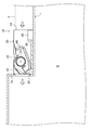
図1に示すように、室内ユニット(10)は、室内空間(S)の天井面が一段下がった下がり天井(1)内に設置されている。室内ユニット(10)は、ケーシング(20)と、クロスフロー型の送風機(30)と、熱交換器(40)と、ドレンパン(50)と、電装品箱(60)とを備えている。クロスフロー型の送風機(30)と熱交換器(40)とドレンパン(50)と電装品箱(60)とは、ケーシング(20)内に形成される空気通路(P)(図2参照)に設置されている。 As shown in FIG. 1, the indoor unit (10) is installed in a lowered ceiling (1) in which the ceiling surface of the indoor space (S) is lowered by one step. The indoor unit (10) includes a casing (20), a cross-flow blower (30), a heat exchanger (40), a drain pan (50), and an electrical component box (60). The cross-flow blower (30), heat exchanger (40), drain pan (50), and electrical component box (60) are connected to the air passage (P) (see FIG. 2) formed in the casing (20). is set up.
ケーシング(20)は、略直方体形状の箱体によって形成されている。具体的には、図1において、ケーシング(20)は、平面視で縦方向(紙面表裏方向)が横方向(左右方向)よりも長く、横方向の長さよりも高さが低い縦長薄型の箱体に構成されている。ケーシング(20)には、横方向の一方の側面(図1では右側の側面)に流入口(21)が形成され、他方の側面(図1では左側の側面)に流出口(22)が形成されている。流入口(21)には、一端が室内空間(S)において開口する吸込ダクト(2)の他端が接続されている。流出口(22)は、ダクト状に形成され、下がり天井(1)の側面(1a)を貫通して室内空間(S)において開口している。 The casing (20) is formed by a substantially rectangular parallelepiped box. Specifically, in FIG. 1, the casing (20) is a vertically long and thin box whose longitudinal direction (front and back direction in the drawing) is longer than the lateral direction (left and right direction) and whose height is lower than the lateral length in plan view. Constructed in the body. In the casing (20), an inflow port (21) is formed on one side surface (right side surface in FIG. 1) and an outflow port (22) is formed on the other side surface (left side surface in FIG. 1). Has been. The other end of the suction duct (2) whose one end opens in the indoor space (S) is connected to the inflow port (21). The outlet (22) is formed in a duct shape and passes through the side surface (1a) of the falling ceiling (1) and opens in the indoor space (S).
クロスフロー型の送風機(30)は、ファンロータ(羽根車)(31)とハウジング(32)とモータ(図示省略)とを有している。クロスフロー型の送風機(30)は、縦方向に長く形成されている。 The cross flow type blower (30) includes a fan rotor (impeller) (31), a housing (32), and a motor (not shown). The crossflow type blower (30) is formed long in the vertical direction.
熱交換器(40)は、ケーシング(20)内において、クロスフロー型の送風機(30)の吸込側に設けられている。熱交換器(40)は、図2に示すように、第1〜第3熱交換部(41〜43)の3つの熱交換部を有している。第1〜第3熱交換部(41〜43)は、クロスフロー型の送風機(30)と同様に、縦方向に長く形成されている。また、第1〜第3熱交換部(41〜43)は、クロスフロー型の送風機(30)の吸込側を取り囲むようにそれぞれ異なる角度で配置されている。 The heat exchanger (40) is provided in the casing (20) on the suction side of the cross-flow blower (30). As shown in FIG. 2, the heat exchanger (40) has three heat exchanging parts, that is, first to third heat exchanging parts (41 to 43). The 1st-3rd heat exchange part (41-43) is formed long in the vertical direction similarly to the cross flow type blower (30). Moreover, the 1st-3rd heat exchange part (41-43) is each arrange | positioned at a different angle so that the suction side of a crossflow type air blower (30) may be surrounded.
ドレンパン(50)は、ケーシング(20)内において、熱交換器(40)の表面で発生した結露水を受け止めるように、熱交換器(40)の下方に設けられている。ドレンパン(50)は、平面視において、縦方向の長さも横方向の長さも熱交換器(40)の各長さよりも長くなるように形成され、受け止めた結露水が漏れないように、外周部が上方に上がり、外周壁を構成している。ドレンパン(50)は、ケーシング(20)の底板上に設置されている。ドレンパン(50)で受け止められた結露水は、図示しないドレンホースを介して屋外へ排出される。 The drain pan (50) is provided below the heat exchanger (40) in the casing (20) so as to receive dew condensation water generated on the surface of the heat exchanger (40). The drain pan (50) is formed so that the length in the vertical direction and the length in the horizontal direction are longer than the respective lengths of the heat exchanger (40) in plan view, so that the condensed water received is not leaked. Rises upward to form an outer peripheral wall. The drain pan (50) is installed on the bottom plate of the casing (20). The condensed water received by the drain pan (50) is discharged to the outside through a drain hose (not shown).
電装品箱(60)は、ケーシング(20)内の流入口(21)と流出口(22)とが対向する横方向において流入口(21)側の端部の底板上に設けられている。つまり、電装品箱(60)は、上記空気通路(P)において、結露水を発生する熱交換器(40)及び結露水を受け止めるドレンパン(50)よりも上流側に配置されている。電装品箱(60)は、ドレンパン(50)の外周壁と間隔を空けて配置され、高さがドレンパン(50)の高さよりも低くなるように形成されている。 The electrical component box (60) is provided on the bottom plate at the end on the inlet (21) side in the lateral direction in which the inlet (21) and the outlet (22) in the casing (20) face each other. That is, the electrical component box (60) is disposed upstream of the heat exchanger (40) that generates condensed water and the drain pan (50) that receives the condensed water in the air passage (P). The electrical component box (60) is disposed so as to be spaced from the outer peripheral wall of the drain pan (50), and is formed so that the height is lower than the height of the drain pan (50).
上述のように、クロスフロー型の送風機(30)は、ファンロータ(羽根車)(31)とハウジング(32)とモータ(図示省略)とを有している。 As described above, the cross-flow blower (30) includes the fan rotor (impeller) (31), the housing (32), and the motor (not shown).
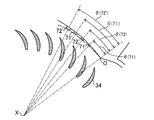
図2及び図3に示すように、ファンロータ(31)は、10枚の円板形状の仕切板(33)と、多数の翼形の羽根(34)と、2つの軸部(35)とを有している。10枚の仕切板(33)は、中心が同一直線上に並ぶように間隔を空けて設けられている。なお、中心を結ぶこの直線は、ファンロータ(31)の中心軸(回転軸)(X)となる。2つの軸部(35)は、10枚の仕切板(33)のうち端に設けられた両端の仕切板(33)の中心部から外側へ突出するように形成されている。2つの軸部(35)の一方の軸部(35)は、ハウジング(32)の後述する側壁部(38)に回転自在に支持され、他方の軸部(35)には、図示しないモータが連結されている。 As shown in FIGS. 2 and 3, the fan rotor (31) includes ten disk-shaped partition plates (33), a number of airfoil blades (34), and two shaft portions (35). have. The ten partition plates (33) are provided at intervals so that the centers are aligned on the same straight line. The straight line connecting the centers is the central axis (rotating axis) (X) of the fan rotor (31). The two shaft portions (35) are formed so as to protrude outward from the center portions of the partition plates (33) at both ends provided at the ends of the ten partition plates (33). One shaft portion (35) of the two shaft portions (35) is rotatably supported by a side wall portion (38) described later of the housing (32), and a motor (not shown) is mounted on the other shaft portion (35). It is connected.
多数の羽根(34)は、10枚の仕切板(33)の各間に、対向する一対の仕切板(33)の外周部に架け渡されている。多数の羽根(34)は、周方向に間隔を空けて配置されている。また、各羽根(34)は、ファンロータ(31)の周方向において回転方向(図2の矢印で示す方向)の逆側へ膨出するように湾曲すると共に、ファンロータ(31)の径方向において内側の部分ほど、周方向において回転方向と逆側に位置するように径方向に対して傾斜した姿勢で配列されている。 A large number of blades (34) are spanned around the outer periphery of a pair of opposing partition plates (33) between each of the ten partition plates (33). A large number of blades (34) are arranged at intervals in the circumferential direction. Each blade (34) is curved so as to bulge to the opposite side of the rotational direction (the direction indicated by the arrow in FIG. 2) in the circumferential direction of the fan rotor (31), and the radial direction of the fan rotor (31). Are arranged in a posture inclined with respect to the radial direction so as to be located on the opposite side to the rotational direction in the circumferential direction.
本実施形態では、ファンロータ(31)は、互いに対向する一対の仕切板(33)とその互いの外周部を連結するように設けられた複数の羽根(34)とによって形成される連が、軸方向に9つ繋がるように形成されている。 In the present embodiment, the fan rotor (31) has a series formed by a pair of partition plates (33) facing each other and a plurality of blades (34) provided to connect the outer peripheral portions of each other. Nine are connected in the axial direction.
図2に示すように、ハウジング(32)は、空気の吸込口(32a)と吹出口(32b)とが形成され、内部にファンロータ(31)が収容されるように筺状に形成されている。ハウジング(32)は、ファンロータ(31)の下側に設けられる下壁部(36)と、ファンロータ(31)の上側に設けられる上壁部(37)と、ファンロータ(31)の軸方向の両端部に設けられる2つの側壁部(38)とを有している。 As shown in FIG. 2, the housing (32) has an air inlet (32a) and an air outlet (32b), and is formed in a bowl shape so that the fan rotor (31) is accommodated therein. Yes. The housing (32) includes a lower wall portion (36) provided below the fan rotor (31), an upper wall portion (37) provided above the fan rotor (31), and a shaft of the fan rotor (31). And two side wall portions (38) provided at both ends in the direction.
下壁部(36)は、ファンロータ(31)の中心軸(X)よりも下方且つ吹出口(32b)側において、ファンロータ(31)の軸方向に長く形成されている。下壁部(36)は、舌部(36a)と、下側延長部(第1の壁部)(36b)と、シール部(36c)とを有している。 The lower wall portion (36) is formed longer in the axial direction of the fan rotor (31) below the center axis (X) of the fan rotor (31) and on the outlet (32b) side. The lower wall portion (36) includes a tongue portion (36a), a lower extension portion (first wall portion) (36b), and a seal portion (36c).
舌部(36a)は、ファンロータ(31)の中心軸(X)よりも下方且つ吹出口(32b)側の部分に近接して対向し、ファンロータ(31)の軸方向に長く延びている。舌部(36a)の下端は、吸込口(32a)を形成している。 The tongue portion (36a) is opposed to the portion below the central axis (X) of the fan rotor (31) and close to the outlet (32b) side, and extends in the axial direction of the fan rotor (31). . The lower end of the tongue (36a) forms a suction port (32a).
下側延長部(36b)は、舌部(36a)の上端に連続し、該舌部(36a)の上端から略L字状に折れ曲がるように形成されている。下側延長部(36b)は、舌部(36a)の上端から斜め下方に延び、吹出口(32b)まで延びている。つまり、下側延長部(36b)の下端は、吹出口(32b)を形成している。 The lower extension (36b) is continuous with the upper end of the tongue (36a) and is formed to be bent in a substantially L shape from the upper end of the tongue (36a). The lower extension (36b) extends obliquely downward from the upper end of the tongue (36a) and extends to the air outlet (32b). That is, the lower end of the lower extension (36b) forms a blower outlet (32b).
シール部(36c)は、下側延長部(36b)の下面から舌部(36a)に略平行に延びている。シール部(36c)は、下端が第1熱交換部(41)に当接して、流入口(21)からケーシング(20)内に流入した空気が、熱交換器(40)を迂回してクロスフロー型の送風機(30)に吸い込まれないように吸込口(32a)と熱交換器(40)との隙間をシールしている。 The seal part (36c) extends substantially parallel to the tongue part (36a) from the lower surface of the lower extension part (36b). The lower end of the seal portion (36c) is in contact with the first heat exchange portion (41), and the air flowing into the casing (20) from the inlet (21) bypasses the heat exchanger (40) and crosses it. The gap between the suction port (32a) and the heat exchanger (40) is sealed so as not to be sucked into the flow type blower (30).
上壁部(37)は、ファンロータ(31)の中心軸(X)よりも上方において、ファンロータ(31)の軸方向に長く形成され、上側の外周面を広く覆っている。上壁部(37)は、スクロール壁部(37a)と、上側延長部(第2の壁部)(37b)と、シール部(37c)とを有している。 The upper wall portion (37) is formed longer in the axial direction of the fan rotor (31) above the central axis (X) of the fan rotor (31), and widely covers the upper outer peripheral surface. The upper wall portion (37) has a scroll wall portion (37a), an upper extension portion (second wall portion) (37b), and a seal portion (37c).
スクロール壁部(37a)は、一端部を除く部分が渦巻き形状に形成された壁部であり、ファンロータ(31)の中心軸(X)よりも上方において、ファンロータ(31)の軸方向に長く延び、ファンロータ(31)の外周面を覆っている。スクロール壁部(37a)は、吸込側(図2では右側)の一端が吸込口(32a)を形成し、この吸込口(32a)を含む一端部は、上流側から下流側に向かうほどファンロータ(31)に近接するように形成されている。スクロール壁部(37a)は、ファンロータ(31)に最も近接する近接部(スクロールの巻き始め点(O):ファンロータ(31)から間隔が拡がっていくスクロール形状の起点)から下流側(吹出口(32b)側)に向かうほどファンロータ(31)から離れるように形成されている。スクロール壁部(37a)は、舌部(36a)の上端部の真上の位置まで延びている。また、スクロール壁部(37a)の近接部と舌部(36a)の近接部とは、ファンロータ(31)の中心軸(X)を挟んで反対側に位置している。 The scroll wall portion (37a) is a wall portion formed in a spiral shape except for one end portion, and in the axial direction of the fan rotor (31) above the central axis (X) of the fan rotor (31). It extends long and covers the outer peripheral surface of the fan rotor (31). In the scroll wall (37a), one end on the suction side (right side in FIG. 2) forms a suction port (32a), and the one end including the suction port (32a) increases toward the downstream side from the upstream side. It is formed so as to be close to (31). The scroll wall (37a) is located on the downstream side of the adjacent portion closest to the fan rotor (31) (the scroll start point (O): the scroll-shaped starting point where the distance from the fan rotor (31) increases). It forms so that it may leave | separate from a fan rotor (31), so that it goes to an exit (32b side). The scroll wall (37a) extends to a position directly above the upper end of the tongue (36a). Further, the proximity portion of the scroll wall portion (37a) and the proximity portion of the tongue portion (36a) are located on opposite sides of the central axis (X) of the fan rotor (31).
上側延長部(37b)は、舌部(36a)の上端部の真上の位置においてスクロール壁部(37a)に滑らかに連続するように形成されている。上側延長部(37b)は、下側延長部(36b)に対向するように該下側延長部(36b)に略平行に延び、吹出口(32b)まで延びている。つまり、上側延長部(37b)の下端は、吹出口(32b)を形成している。 The upper extension (37b) is formed so as to be smoothly connected to the scroll wall (37a) at a position directly above the upper end of the tongue (36a). The upper extension (37b) extends substantially parallel to the lower extension (36b) so as to face the lower extension (36b), and extends to the outlet (32b). That is, the lower end of the upper extension (37b) forms a blower outlet (32b).
シール部(37c)は、スクロール壁部(37a)の一端部の上面からケーシング(20)の天板に向かって斜め上方に延びている。シール部(37c)は、下面が第3熱交換部(43)に当接して、流入口(21)からケーシング(20)内に流入した空気が、熱交換器(40)を迂回してクロスフロー型の送風機(30)に吸い込まれないように吸込口(32a)と熱交換器(40)との隙間をシールしている。 The seal portion (37c) extends obliquely upward from the upper surface of one end portion of the scroll wall portion (37a) toward the top plate of the casing (20). The lower surface of the seal portion (37c) is in contact with the third heat exchange portion (43), and the air flowing into the casing (20) from the inlet (21) bypasses the heat exchanger (40) and crosses it. The gap between the suction port (32a) and the heat exchanger (40) is sealed so as not to be sucked into the flow type blower (30).
2つの側壁部(38)は、ファンロータ(31)の軸方向の両端部に設けられている。2つの側壁部(38)は、下端部が熱交換器(40)の上端面に沿うように形成され、上端部は、スクロール壁部(37a)の上端部に対応するように形成されている。また、2つの側壁部(38)には、ファンロータ(31)の軸部(35)の挿通孔が形成され、軸部(35)が挿通される。2つの側壁部(38)は、上記ケーシング(20)の空気通路(P)内で、下壁部(36)と上壁部(37)との間に、吸込口(32a)から吹出口(32b)へ向かう空気流路を形成している。また、2つの側壁部(38)は、下壁部(36)の下側延長部(36b)と上壁部(37)の上側延長部(37b)との間に、ファンロータ(31)から吹き出される吹出空気を吹出口(32b)に導く吹出流路(F)を形成している。 The two side wall portions (38) are provided at both end portions in the axial direction of the fan rotor (31). The two side wall portions (38) are formed such that the lower end portions are along the upper end surface of the heat exchanger (40), and the upper end portions are formed so as to correspond to the upper end portions of the scroll wall portion (37a). . The two side wall portions (38) are formed with insertion holes for the shaft portion (35) of the fan rotor (31), and the shaft portion (35) is inserted therethrough. The two side wall portions (38) are arranged between the air inlet (32a) and the air outlet (32) between the lower wall portion (36) and the upper wall portion (37) in the air passage (P) of the casing (20). The air flow path toward 32b) is formed. Further, the two side wall portions (38) are arranged between the fan rotor (31) between the lower extension portion (36b) of the lower wall portion (36) and the upper extension portion (37b) of the upper wall portion (37). The blowout flow path (F) which guides the blown-out blown air to the blowout outlet (32b) is formed.
上記ハウジング(32)の吹出流路(F)には、上記ファンロータ(31)の外周円との間隔が流路の上流から下流へ向かって漸次大きくなる上記スクロール壁部(37a)により、拡大流路(70)が形成されている。そして、このスクロール壁部(37a)の巻き始め点(O)の下流側に、該スクロール壁部(37a)の壁面から上記ファンロータ831)側へ突出する2つの突起(71,72)が形成されている。これら2つの突起(71,72)は、上記巻き始め点(O)に近い方の突起を第1突起(71)、上記巻き始め点(O)から遠い方の突起を第2突起(72)という。 The air flow path (F) of the housing (32) is enlarged by the scroll wall (37a) in which the distance from the outer peripheral circle of the fan rotor (31) gradually increases from the upstream to the downstream of the flow path. A flow path (70) is formed. And two protrusions (71, 72) projecting from the wall surface of the scroll wall (37a) toward the fan rotor 831) are formed on the downstream side of the winding start point (O) of the scroll wall (37a). Has been. These two protrusions (71, 72) are formed such that the protrusion closer to the winding start point (O) is the first protrusion (71), and the protrusion farther from the winding start point (O) is the second protrusion (72). That's it.
図4は、図3の要部拡大図である。本実施形態において、上記拡大流路(70)の拡大面積比τは、τ≦1.39である。また、上記スクロール壁部(37a)の巻き始め点(O)に対する上記突起(71,72)の位置を上記ファンロータ(31)の中心角で表した角度θ(°)と、該突起(71,72)の突出高さH(mm)との関係が、H(Hmax)≦2.2τθで表される関係を満たしている。 4 is an enlarged view of a main part of FIG. In the present embodiment, the expansion area ratio τ of the expansion flow path (70) is τ ≦ 1.39. Further, the angle θ (°) representing the position of the protrusion (71, 72) relative to the winding start point (O) of the scroll wall portion (37a) with the central angle of the fan rotor (31), and the protrusion (71 , 72) satisfies the relationship represented by H (Hmax) ≦ 2.2τθ.
ここで、拡大面積比τは、図4において、τ=(A1+A2)/A1で表される。また、A1=π×r02である。 Here, the enlarged area ratio τ is represented by τ = (A1 + A2) / A1 in FIG. Further, it is A1 = π × r0 2.
なお、上記の式において、r0は、ケーシングの拡大流路がなす曲線の開始始点とクロスフローファンの回転中心とを結ぶ線分の長さ、A1は、R0(点(X)から点(O)までの距離r0)を半径とする円弧Cで区画される90°の扇形の面積、A2は、ファンロータ(31)の中心(X)を通り線分r0となす角度θが90°となる直線Lが拡大流路曲線と交差する点Qとで囲まれた面積からA1を差し引いた面積(A1に対して拡大されている部分の面積)である。 In the above equation, r0 is the length of the line segment connecting the start point of the curve formed by the enlarged flow path of the casing and the rotation center of the cross flow fan, and A1 is R0 (from point (X) to point (O ) Is a 90 ° fan-shaped area partitioned by an arc C having a radius r0), and the angle θ between the center (X) of the fan rotor (31) and the line segment r0 is 90 °. The area obtained by subtracting A1 from the area surrounded by the point Q where the straight line L intersects the enlarged flow path curve (the area of the part enlarged with respect to A1).
また、本実施形態では、上記第1突起(71)の高さH(mm)は、H=0.5である。具体的には、第1突起(71)の高さH(mm)は、0.5≦H≦0.7であればよい。また、上記第2突起(72)の高さH(mm)は、H=0.75である。 In the present embodiment, the height H (mm) of the first protrusion (71) is H = 0.5. Specifically, the height H (mm) of the first protrusion (71) may be 0.5 ≦ H ≦ 0.7. The height H (mm) of the second protrusion (72) is H = 0.75.
−運転動作−
空気調和装置の室内ユニット(10)では、クロスフロー型の送風機(30)の起動により、ケーシング(20)内で流入口(21)から流出口(22)に向かう空気通路(P)において空気流れが形成される。これにより、室内空間(S)の室内空気が吸込ダクト(2)を介してケーシング(20)内に流入する。流入口(21)からケーシング(20)内に流入した空気は、熱交換器(40)を通過する際に、冷媒と熱交換し、温度が調節(加熱又は冷却)される。温調後の空気は、送風機(30)に吸い込まれて、ハウジング(32)内に形成された空気流路を流れて吹出口(32b)から吹き出される。送風機(30)から吹き出された空気は、流出口(22)から室内空間(S)に供給される。この空気によって室内空間(S)の室内空気の温度が調節される。
-Driving action-
In the indoor unit (10) of the air conditioner, the air flow in the air passage (P) from the inlet (21) to the outlet (22) in the casing (20) is activated by the activation of the cross flow blower (30). Is formed. Thereby, indoor air in the indoor space (S) flows into the casing (20) through the suction duct (2). The air flowing into the casing (20) from the inlet (21) exchanges heat with the refrigerant when passing through the heat exchanger (40), and the temperature is adjusted (heated or cooled). The temperature-adjusted air is sucked into the blower (30), flows through the air flow path formed in the housing (32), and is blown out from the outlet (32b). The air blown out from the blower (30) is supplied from the outlet (22) to the indoor space (S). The temperature of the indoor air in the indoor space (S) is adjusted by this air.
〈送風機での空気の流れ〉
クロスフロー型の送風機(30)において、ファンロータ(31)が回転すると、ハウジング(32)内にファンロータ(31)を貫く空気流れが形成される(図2の白抜き矢印を参照)。この空気流れは、ファンロータ(31)の羽根(34)の湾曲形状により、略S字状の流れとなる。ファンロータ(31)から吹き出された吹出空気は、吹出流路(F)に流入する。吹出流路(F)を流れる吹出空気は、吹出口(32b)に至り、吹出口(32b)から吹き出される。
<Air flow in the blower>
In the cross-flow type blower (30), when the fan rotor (31) rotates, an air flow passing through the fan rotor (31) is formed in the housing (32) (see the white arrow in FIG. 2). This air flow becomes a substantially S-shaped flow due to the curved shape of the blades (34) of the fan rotor (31). The blown air blown out from the fan rotor (31) flows into the blowout flow path (F). The blown air flowing through the blowout flow path (F) reaches the blowout port (32b) and is blown out from the blowout port (32b).
〈実施例と比較例の対比〉
次に、図5〜図8を用いて、本実施形態の突起(71,72)を形成した実施例と、θやHの寸法が異なる突起(71’,72’)を形成した比較例とを対比して説明する。
<Contrast of Examples and Comparative Examples>
Next, with reference to FIGS. 5 to 8, an example in which the protrusions (71, 72) of the present embodiment are formed and a comparative example in which protrusions (71 ′, 72 ′) having different dimensions of θ and H are formed. A comparison will be made.
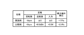
図7に示すように、実施例では、第1突起(71)は、θ=13.6,H=0.5で形成され、第2突起(72)は、θ=16.4,H=0.75で形成されている。この場合、Hmaxは、第1突起(71)と第2突起(72)についてそれぞれ0.7及び0.8となり、H<Hmaxとなっている。 As shown in FIG. 7, in the embodiment, the first protrusion (71) is formed with θ = 13.6, H = 0.5, and the second protrusion (72) is θ = 16.4, H =. It is formed at 0.75. In this case, Hmax is 0.7 and 0.8 for the first protrusion (71) and the second protrusion (72), respectively, and H <Hmax.
一方、比較例では、第1突起(71’)は、θ=21.2,H=1.15で形成され、第2突起(72’)は、θ=26.4,H=1.75で形成されている。この場合、Hmaxは、それぞれ1.0及び1.3となり、実施例とは逆にH>Hmaxになっている。 On the other hand, in the comparative example, the first protrusion (71 ′) is formed with θ = 21.2 and H = 1.15, and the second protrusion (72 ′) is θ = 26.4, H = 1.75. It is formed with. In this case, Hmax is 1.0 and 1.3, respectively, and H> Hmax, contrary to the embodiment.
また、図8に示すように、送風機(30)の定格運転時に、実施例では送風音やモータ入力が抑えられ、最大機外静圧が高い(風速が遅い)のに対して、比較例では突起がH(Hmax)≦2.2τθの値を超えて大きいために、最大機外静圧が低く(風速が速く)なってしまい、送風音が大きくなるとともにモータ入力も大きくなっている。これは、実施例では、突起(71’,72’)が大きくてファンロータ(34)との間の空間が狭くなって流速が速くなりすぎ、かつ突起が風の流れと干渉して乱れが発生したためと考えられ、その結果、騒音が大きくなり、サージング抑制効果も小さくなってしまう。 Further, as shown in FIG. 8, during rated operation of the blower (30), in the example, the blowing sound and motor input are suppressed, and the maximum static pressure outside the machine is high (wind speed is slow), whereas in the comparative example, Since the protrusion is larger than the value of H (Hmax) ≦ 2.2τθ, the maximum static pressure outside the machine is low (the wind speed is high), the blowing sound is increased and the motor input is also increased. This is because, in the embodiment, the protrusions (71 ′, 72 ′) are large, the space between the fan rotor (34) is narrowed and the flow velocity becomes too fast, and the protrusions interfere with the wind flow and are disturbed. As a result, the noise increases and the surging suppression effect also decreases.
−実施形態の効果−
本実施形態によれば、ハウジング(32)のスクロール壁部(37a)の巻き始め点(O)の下流側に、スクロール壁部(37a)の壁面からファンロータ(31)側へ突出する突起(71,72)が形成されたクロスフロー型の送風機(30)において、拡大流路(70)の拡大面積比τをτ≦1.39とし、第1突起(71)の位置(角度)θと突出高さHとの関係をH≦2.2τθとしたこと(具体的にはH≦0.7にしたこと)により、第1突起(71)が大きくなりすぎるのを抑えられるから、第1突起(71)が風の流れと干渉して乱れが発生するのを抑えられる。
-Effect of the embodiment-
According to this embodiment, on the downstream side of the winding start point (O) of the scroll wall portion (37a) of the housing (32), a protrusion (from the wall surface of the scroll wall portion (37a) to the fan rotor (31) side ( 71, 72) In the crossflow type blower (30) in which the enlarged flow path (70) is formed, the enlarged area ratio τ is set to τ ≦ 1.39, and the position (angle) θ of the first protrusion (71) is Since the relationship with the protrusion height H is H ≦ 2.2τθ (specifically, H ≦ 0.7), the first protrusion (71) can be prevented from becoming too large. It is possible to prevent the protrusion (71) from interfering with the wind flow and generating turbulence.
したがって、本実施形態によれば、スクロール壁部(37a)の拡大面積比τを1.39よりも小さくした場合に、ファンロータ(31)とスクロール壁部(37a)の距離が接近しすぎて損失が大きくなるのを抑えられる。以上のように、本実施形態によれば、ケーシング(20)の流入口にダクト(2)が接続され、機外静圧の高い空気調和装置の室内ユニット(10)において、クロスフロー型の送風機(30)のハウジング(32)内で風の流れが乱れるのを抑え、騒音や消費電力が増大するのを抑制するとともに、サージング抑制効果も高められる。 Therefore, according to this embodiment, when the enlarged area ratio τ of the scroll wall portion (37a) is made smaller than 1.39, the distance between the fan rotor (31) and the scroll wall portion (37a) is too close. Increase in loss can be suppressed. As described above, according to the present embodiment, the duct (2) is connected to the inlet of the casing (20), and the cross-flow type blower is used in the indoor unit (10) of the air conditioner with high external static pressure. It suppresses the disturbance of the wind flow in the housing (32) of (30), suppresses the increase in noise and power consumption, and enhances the surging suppression effect.
また、本実施形態によれば、突起の高さH(mm)をH≧0.5にして、突起が小さくなりすぎるのを抑制しているので、スクロール壁部(37a)に突起を容易に形成できる効果もある。 In addition, according to the present embodiment, the height H (mm) of the protrusion is set to H ≧ 0.5 to suppress the protrusion from becoming too small, so that the protrusion can be easily formed on the scroll wall portion (37a). There is also an effect that can be formed.
《その他の実施形態》
上記実施形態については、以下のような構成としてもよい。
<< Other Embodiments >>
About the said embodiment, it is good also as the following structures.
上記実施形態では、天井内に設置される室内ユニット(10)に本発明に係るクロスフロー型の送風機(30)を適用した例について説明したが、本発明に係るクロスフロー型の送風機(30)が適用される室内ユニット(10)の構成は上述のものに限られない。室内空間に設置されるものであってもよい。 In the above embodiment, the example in which the crossflow type blower (30) according to the present invention is applied to the indoor unit (10) installed in the ceiling has been described. However, the crossflow type blower (30) according to the present invention is described. The configuration of the indoor unit (10) to which is applied is not limited to the above. It may be installed in an indoor space.
また、上記実施形態では、室内ユニット(10)は、流入口(21)と流出口(22)とが対向する2つの側面に形成されたケーシング(20)を備えるように構成されているが、ケーシング(20)における流入口(21)と流出口(22)の位置は、上述のものに限られない。例えば、ケーシング(20)の下面に流入口(21)が形成され、一側面に流出口(22)が形成されていてもよい。 Moreover, in the said embodiment, although an indoor unit (10) is comprised so that the inflow port (21) and the outflow port (22) may be provided with the casing (20) formed in two side surfaces, The positions of the inlet (21) and the outlet (22) in the casing (20) are not limited to those described above. For example, the inlet (21) may be formed on the lower surface of the casing (20), and the outlet (22) may be formed on one side surface.
また、上記実施形態では、ケーシング(20)の流入口(21)にのみ吸込ダクト(2)が接続された構成を説明したが、本発明は、上記ケーシング(20)の流入口(21)及び流出口(22)の両方、あるいは流出口(22)にのみダクトが接続された室内ユニット(10)にも適用可能である。 Further, in the above-described embodiment, the configuration in which the suction duct (2) is connected only to the inlet (21) of the casing (20) has been described, but the present invention relates to the inlet (21) and the casing (20) of the casing (20). The present invention is also applicable to the indoor unit (10) in which a duct is connected to both the outlet (22) or only to the outlet (22).
さらに、本発明のクロスフロー型の送風機(30)は、高静圧の室外ユニット(10)だけを設置対象にしたものではなく、ダクトのような流路の抵抗になるものが接続されない大風量の室外ユニットに設けてもよい。 Furthermore, the crossflow type blower (30) of the present invention is not intended for the installation of only the high static pressure outdoor unit (10), but a large air volume that is not connected to a duct that acts as a flow path resistance. It may be provided in the outdoor unit.
以上説明したように、本発明は、室内ユニットに用いられるクロスフロー型の送風機のサージングを抑制する構造について有用である。 As described above, the present invention is useful for a structure that suppresses surging of a crossflow type blower used in an indoor unit.
2 吸込ダクト
10 室内ユニット
20 ケーシング
21 流入口
22 流出口
30 クロスフロー型の送風機
31 ファンロータ(羽根車)
32 ハウジング
32a 吸込口
32b 吹出口
34 羽根
37a スクロール壁部
40 熱交換器
70 拡大流路
71 巻き始め点
71 第1突起
72 第2突起
F 吹出流路
H 突出高さ
X 中心軸(回転軸)
θ 中心角
τ 拡大面積比
2 Suction duct
10 Indoor unit
20 casing
21 Inlet
22 Outlet
30 Cross-flow blower
31 Fan rotor
32 Housing
32a inlet
32b outlet
34 feathers
37a Scroll wall
40 heat exchanger
70 Expanded flow path
71 Starting point of winding
71 First protrusion
72 2nd projection F Blowing flow path H Projection height X Center axis (rotary axis)
θ Center angle τ Expansion area ratio
本発明は、クロスフロー型の送風機及びそれを備えた空気調和装置の室内ユニットに関し、特に、クロスフロー型の送風機においてサージングを抑制する構造に関するものである。 The present invention relates to a crossflow type blower and an indoor unit of an air conditioner including the same, and more particularly to a structure that suppresses surging in a crossflow type blower.
従来、空気調和装置の室内ユニットにおいて、クロスフロー型の送風機が用いられている(例えば、下記の特許文献1を参照)。 Conventionally, a crossflow type blower is used in an indoor unit of an air conditioner (see, for example, Patent Document 1 below).
クロスフロー型の送風機は、複数の羽根を有して中心軸周りに回転する円筒状のファンロータと、空気の吸込口と吹出口とが形成されて上記ファンロータが収納されたハウジングとを備えている。このクロスフロー型の送風機では、ハウジング内においてファンロータが中心軸周りに回転することにより、吸込口からハウジング内に吸い込まれた空気がファンロータを貫いて吹出口に向かって流れる。 A cross-flow type blower includes a cylindrical fan rotor having a plurality of blades and rotating around a central axis, and a housing in which an air inlet and an outlet are formed and the fan rotor is accommodated. ing. In this cross-flow type blower, the air that is sucked into the housing from the suction port flows through the fan rotor toward the blower outlet when the fan rotor rotates around the central axis in the housing.
上記クロスフロー型の送風機は、上記空気調和装置の室内ユニットのケーシング内に形成されている空気通路に配置されている。また、上記ケーシングの空気通路には、内部を流れる冷媒が空気と熱交換することにより、空気が加熱または冷却される熱交換器も配置されている。 The crossflow type blower is disposed in an air passage formed in a casing of the indoor unit of the air conditioner. In addition, a heat exchanger that heats or cools the air is also arranged in the air passage of the casing by heat exchange between the refrigerant flowing inside and the air.
クロスフロー型の送風機では、一般に、ハウジングには、ファンロータから吹出口に向かって空気が流れる領域に、徐々に空気流路の面積が大きくなるスクロール壁部が設けられている。スクロールの拡大面積比τは、図4において、τ=(A1+A2)/A1で表される。なお、A1=π×r02である。 In a cross-flow type blower, generally, the housing is provided with a scroll wall portion in which the area of the air flow passage gradually increases in a region where air flows from the fan rotor toward the outlet. The scroll enlarged area ratio τ is represented by τ = (A1 + A2) / A1 in FIG. Note that A1 = π × r02.
上記の式において、r0は、ケーシングの拡大流路がなす曲線の開始始点とクロスフローファンの回転中心とを結ぶ線分の長さ、A1はR0を半径とする扇形の面積、A2はファン中心より線分r0となす角度θが90°となる直線が拡大流路曲線と交差する点Qとで囲まれた面積からA1を差し引いた面積(A1に対して拡大されている部分)である。 In the above equation, r0 is the length of a line segment connecting the start point of the curve formed by the enlarged flow path of the casing and the rotation center of the cross flow fan, A1 is a fan-shaped area with radius R0, and A2 is the fan center A straight line with an angle θ of 90 ° formed by the twisted line segment r0 is an area obtained by subtracting A1 from an area surrounded by a point Q that intersects the enlarged flow path curve (a portion enlarged with respect to A1).
特許文献2では、この特許文献2の従来技術として挙げられている拡大面積比τ=1.39に対して、1.416≦τ≦1.466にすることで、送風効率を高めることができると記載されている。
In
また、スクロール壁面からの空気の逆流によるサージング(圧力や吐出量の周期的な変動)の発生を抑制する手段として、特許文献3には、スクロールの巻き始め付近に複数の突起を設けることが記載されており、空気流れの上流側の突起よりも下流側の突起を大きくすることで、高いサージング抑制効果が得られると記載されている。 Further, as means for suppressing the occurrence of surging (periodic fluctuations in pressure and discharge amount) due to the backflow of air from the scroll wall surface, Patent Document 3 describes that a plurality of protrusions are provided in the vicinity of the scroll start. It is described that a high surging suppression effect can be obtained by making the protrusion on the downstream side larger than the protrusion on the upstream side of the air flow.
ところで、ケーシングの空気流入側や空気流出側にダクトが接続されるタイプの室内ユニットにクロスフロー型の送風機を適用する場合、運転時の機外静圧(圧力損失)が高くなり、そのような条件ではファンの回転数に対して風量が減少することから、スクロール壁部の壁面で流速が遅くなる傾向があり、そこから空気の逆流が発生してサージングが生じやすくなるという問題があった。 By the way, when a cross-flow type blower is applied to an indoor unit in which a duct is connected to the air inflow side or the air outflow side of the casing, the external static pressure (pressure loss) during operation increases. Under the conditions, since the air volume decreases with respect to the rotational speed of the fan, there is a tendency that the flow velocity tends to be slow on the wall surface of the scroll wall portion, and a backflow of air is generated therefrom, and surging is likely to occur.
そこで、クロスフロー型の送風機においてサージングの発生を抑制するために、スクロール壁部の拡大面積比τを1.39よりもさらに小さくし、ファンとスクロールの距離を狭くしてスクロール壁面の流速を大きくすることにより、逆流の発生を抑制することが考えられる。 Therefore, in order to suppress the occurrence of surging in the cross-flow type blower, the scroll wall portion enlargement area ratio τ is made smaller than 1.39, the distance between the fan and the scroll is narrowed, and the scroll wall flow velocity is increased. By doing so, it is conceivable to suppress the occurrence of backflow.
しかしながら、拡大面積比が小さくなればなるほど、ファンロータとスクロール壁部の距離が接近するので損失が大きくなり、騒音や消費電力が増大するおそれがあった。つまり、拡大面積比τが1.39よりも小さい場合、単にスクロール壁部の巻き始め付近に突起を設けただけでは、騒音や消費電力を抑えることが困難であった。 However, the smaller the enlargement area ratio is, the closer the fan rotor and the scroll wall portion are to each other, so that the loss increases and the noise and power consumption may increase. That is, when the enlarged area ratio τ is smaller than 1.39, it is difficult to suppress noise and power consumption simply by providing a protrusion near the start of winding of the scroll wall.
本発明は、このような問題点に鑑みてなされたものであり、その目的は、スクロールの拡大面積比τを1.39よりも小さくした場合に、ファンロータとスクロール壁部の距離が接近することで損失が大きくなるのを抑え、騒音や消費電力が増大するのを抑制するとともに、サージングの発生も抑えることである。 The present invention has been made in view of such problems, and its object is to make the distance between the fan rotor and the scroll wall closer when the scroll expansion area ratio τ is smaller than 1.39. Therefore, it is possible to suppress an increase in loss, suppress an increase in noise and power consumption, and suppress the occurrence of surging.
第1の発明は、複数の羽根(34)を有し、中心軸(X)周りに回転するファンロータ(31)と、空気の吸込口(32a)と吹出口(32b)とが形成され、上記ファンロータ(31)が収容されるハウジング(32)とを備え、上記ハウジング(32)が、上記ファンロータ(31)から上記吹出口(32b)へ向かう吹出流路(F)を有し、該吹出流路(F)に、上記ファンロータ(31)の外周円との間隔が流路の上流から下流へ向かって漸次大きくなるスクロール壁部(37a)からなる拡大流路(70)が形成され、上記スクロール壁部(37a)の巻き始め点(O)の下流側に、該スクロール壁部(37a)の壁面から上記ファンロータ(31)側へ突出する少なくとも1つの突起(71)が形成されたクロスフロー型の送風機を前提としている。 The first invention has a plurality of blades (34), a fan rotor (31) rotating around the central axis (X), an air inlet (32a), and an outlet (32b) are formed, A housing (32) in which the fan rotor (31) is housed, and the housing (32) has a blowout flow path (F) from the fan rotor (31) toward the blowout port (32b), An enlarged flow path (70) comprising a scroll wall portion (37a) in which the distance from the outer circumference of the fan rotor (31) gradually increases from the upstream side to the downstream side of the flow path is formed in the blowout flow path (F). And at least one protrusion (71) protruding from the wall surface of the scroll wall (37a) toward the fan rotor (31) on the downstream side of the winding start point (O) of the scroll wall (37a). It is premised on a cross flow type blower.
そして、このクロスフロー型の圧縮機は、上記拡大流路(70)の拡大面積比τが、τ≦1.39であり、上記スクロール壁部(37a)の巻き始め点(O)に対する上記突起(71)の位置を上記ファンロータ(31)の中心角で表した場合の角度θ(°)と、該突起(71)の突出高さH(mm)との関係が、H≦2.2τθで表される関係を満たしていることを特徴としている。 In this cross flow type compressor, the expansion area ratio τ of the expansion flow path (70) is τ ≦ 1.39, and the protrusion with respect to the winding start point (O) of the scroll wall portion (37a). The relationship between the angle θ (°) when the position of (71) is expressed by the central angle of the fan rotor (31) and the protrusion height H (mm) of the protrusion (71) is H ≦ 2.2τθ It is characterized by satisfying the relationship represented by.
この第1の発明では、ハウジング(32)のスクロール壁部(37a)の巻き始め点(O)の下流側に、スクロール壁部(37a)の壁面からファンロータ(31)側へ突出する少なくとも1つの突起(71)が形成されたクロスフローファンにおいて、拡大流路(70)の拡大面積比τをτ≦1.39とし、突起(71)の位置(角度)θと突出高さHとの関係をH≦2.2τθとしているので、突起(71)が大きくなりすぎるのを抑えられる。突起(71)が大きいと風の乱れが生じやすいが、本発明では突起(71)の大きさをH≦2.2τθの式により規制しているので、突起(71)が風の流れと干渉して乱れが発生するのを抑えられる。 In the first invention, at least one projecting from the wall surface of the scroll wall portion (37a) toward the fan rotor (31) on the downstream side of the winding start point (O) of the scroll wall portion (37a) of the housing (32). In the cross flow fan in which the two protrusions (71) are formed, the expansion area ratio τ of the expansion flow path (70) is τ ≦ 1.39, and the position (angle) θ of the protrusion (71) and the protrusion height H Since the relationship is H ≦ 2.2τθ, the protrusion (71) can be prevented from becoming too large. If the protrusion (71) is large, wind turbulence is likely to occur, but in the present invention, since the size of the protrusion (71) is regulated by the expression H ≦ 2.2τθ, the protrusion (71) interferes with the flow of the wind. Thus, the occurrence of disturbance can be suppressed.
また、第1の発明は、上記スクロール壁部(37a)の巻き始め点(O)に最も近い突起(71)の高さH(mm)が、H≦0.7であることを特徴としている。 Further, the first invention is characterized in that the height H (mm) of the projection (71) closest to the winding start point (O) of the scroll wall portion (37a) is H ≦ 0.7. .
この第1の発明では、H≦0.7の関係が満たされているので、突起(71)が大きくなりすぎるのを抑えられ、ひいては突起(71)が風の流れと干渉して乱れが発生するのを抑えられる。 In the first invention , since the relationship of H ≦ 0.7 is satisfied, it is possible to suppress the protrusion (71) from becoming too large, and as a result, the protrusion (71) interferes with the wind flow and turbulence occurs. Can be suppressed.
第2の発明は、第1の発明において、上記突起(71)の高さH(mm)が、H≧0.5であることを特徴としている。 The second invention is characterized in that, in the first invention, a height H (mm) of the protrusion (71) is H ≧ 0.5.
この第2の発明では、突起(71)の高さH(mm)がH≧0.5になるようにしているので、突起(71)が小さくなりすぎるのを抑制できる。 In the second aspect of the invention , since the height H (mm) of the protrusion (71) satisfies H ≧ 0.5, the protrusion (71) can be prevented from becoming too small.
第3の発明は、室内空気の温度を調節する空気調和装置の室内ユニットであって、空気の流入口(21)と流出口(22)とが形成されたケーシング(20)と、上記ケーシング(20)内に設けられて上記流入口(21)から上記流出口(22)へ流れる空気流れを形成する第1または第2の発明のクロスフロー型の送風機(30)と、上記ケーシング(20)内で上記クロスフロー型の送風機(30)に対して上記空気流れの上流側に設けられて空気を加熱または冷却する熱交換器(40)と、を備えていることを特徴としている。 3rd invention is an indoor unit of the air conditioning apparatus which adjusts the temperature of room air, Comprising: The casing (20) in which the inflow port (21) and the outflow port (22) of air were formed, The said casing ( 20) The cross-flow type blower (30) of the first or second invention which is provided in the inside and forms an air flow flowing from the inlet (21) to the outlet (22), and the casing (20) And a heat exchanger (40) provided on the upstream side of the air flow with respect to the cross flow type blower (30) to heat or cool the air.
この第3の発明では、空気調和装置の室内ユニットにおいて、クロスフロー型の送風機(30)のハウジング(32)内で風の流れが乱れるのを抑えられる。 According to the third aspect of the invention , in the indoor unit of the air conditioner, it is possible to suppress the turbulence of the wind flow in the housing (32) of the crossflow type blower (30).
第4の発明は、第3の発明において、上記ケーシング(20)の流入口(21)及び流出口(22)の一方または両方にダクト(2)が接続されることを特徴としている。 According to a fourth aspect, in the third aspect, the duct (2) is connected to one or both of the inlet (21) and the outlet (22) of the casing (20).
この第4の発明では、ケーシング(20)の流入口(21)及び流出口(22)の一方または両方にダクト(2)が接続されることで機外静圧が高くなる空気調和装置の室内ユニットにおいて、クロスフロー型の送風機(30)のハウジング(32)内で風の流れが乱れるのを抑えられる。 According to the fourth aspect of the invention , the interior of the air conditioner where the external static pressure is increased by connecting the duct (2) to one or both of the inlet (21) and the outlet (22) of the casing (20). In the unit, it is possible to prevent the wind flow from being disturbed in the housing (32) of the crossflow type blower (30).
本発明によれば、ハウジング(32)のスクロール壁部(37a)の巻き始め点(O)の下流側に、スクロール壁部(37a)の壁面からファンロータ(31)側へ突出する少なくとも1つの突起(71)が形成されたクロスフローファンにおいて、拡大流路(70)の拡大面積比τをτ≦1.39とし、突起(71)の位置(角度)θと突出高さHとの関係をH≦2.2τθとしたことにより、突起(71)が大きくなりすぎるのを抑えられるから、突起(71)が風の流れと干渉して乱れが発生するのを抑えられる。したがって、スクロールの拡大面積比τを1.39よりも小さくした場合に、単に突起を設けただけのものとは違って、ファンロータ(31)と突起(71)の距離が接近しすぎて損失が大きくなるのを抑えられるから、騒音や消費電力が増大するのを抑制するとともに、サージング抑制効果も高められる。 According to the present invention, at least one protruding from the wall surface of the scroll wall portion (37a) to the fan rotor (31) side downstream of the winding start point (O) of the scroll wall portion (37a) of the housing (32). In the cross flow fan in which the protrusion (71) is formed, the expansion area ratio τ of the expansion flow path (70) is τ ≦ 1.39, and the relationship between the position (angle) θ of the protrusion (71) and the protrusion height H By setting H ≦ 2.2τθ, it is possible to prevent the protrusion (71) from becoming too large, and thus it is possible to suppress the protrusion (71) from interfering with the wind flow and causing turbulence. Therefore, when the enlarged area ratio τ of the scroll is made smaller than 1.39, the distance between the fan rotor (31) and the protrusion (71) is too close, unlike the case of merely providing the protrusion. Therefore, the increase in noise and power consumption can be suppressed, and the surging suppression effect can be enhanced.
上記第1の発明によれば、H≦0.7の関係を満たすことにより、突起(71)が大きくなりすぎるのを抑え、ひいては突起(71)が風の流れと干渉して乱れを発生させるのを抑えられるから、騒音や消費電力が増大するのを抑制するとともに、サージング抑制効果も高められる。 According to the first aspect of the present invention , by satisfying the relationship of H ≦ 0.7, the protrusion (71) is prevented from becoming too large, and the protrusion (71) interferes with the wind flow to cause turbulence. Therefore, the increase in noise and power consumption can be suppressed, and the surging suppression effect can be enhanced.
上記第2の発明によれば、突起(71)の高さH(mm)をH≧0.5にして、突起(71)が小さくなりすぎるのを抑制しているので、スクロール壁部(73a)に突起(71)を容易に形成できる。 According to the second aspect of the invention , the height H (mm) of the protrusion (71) is set to H ≧ 0.5 to suppress the protrusion (71) from becoming too small, so that the scroll wall (73a ) Can easily form the protrusion (71).
上記第3の発明によれば、空気調和装置の室内ユニットにおいて、クロスフロー型の送風機(30)のハウジング(32)内で風の流れが乱れるのを抑え、騒音や消費電力が増大するのを抑制するとともに、サージング抑制効果も高められる。 According to the third aspect of the present invention , in the indoor unit of the air conditioner, the disturbance of the wind flow in the housing (32) of the crossflow type blower (30) is suppressed, and noise and power consumption are increased. While suppressing, a surging suppression effect is also heightened.
上記第4の発明によれば、ケーシング(20)の流入口(21)及び流出口(22)の一方または両方にダクト(2)が接続されることで機外静圧が高くなる空気調和装置の室内ユニットにおいて、クロスフロー型の送風機(30)のハウジング(32)内で風の流れが乱れるのを抑え、騒音や消費電力が増大するのを抑制するとともに、サージング抑制効果も高められる。 According to the fourth aspect of the invention , the air conditioning apparatus in which the external static pressure is increased by connecting the duct (2) to one or both of the inlet (21) and the outlet (22) of the casing (20). In this indoor unit, the disturbance of the wind flow in the housing (32) of the crossflow type blower (30) is suppressed, noise and power consumption are suppressed, and the surging suppression effect is enhanced.
以下、本発明の実施形態に係る空気調和装置の室内ユニットについて図面を参照しながら説明する。なお、以下の実施形態は、本質的に好ましい例示であって、本発明、その適用物、あるいはその用途の範囲を制限することを意図するものではない。 Hereinafter, an indoor unit of an air conditioner according to an embodiment of the present invention will be described with reference to the drawings. The following embodiments are essentially preferable examples, and are not intended to limit the scope of the present invention, its application, or its use.
図1に示すように、室内ユニット(10)は、室内空間(S)の天井面が一段下がった下がり天井(1)内に設置されている。室内ユニット(10)は、ケーシング(20)と、クロスフロー型の送風機(30)と、熱交換器(40)と、ドレンパン(50)と、電装品箱(60)とを備えている。クロスフロー型の送風機(30)と熱交換器(40)とドレンパン(50)と電装品箱(60)とは、ケーシング(20)内に形成される空気通路(P)(図2参照)に設置されている。 As shown in FIG. 1, the indoor unit (10) is installed in a lowered ceiling (1) in which the ceiling surface of the indoor space (S) is lowered by one step. The indoor unit (10) includes a casing (20), a cross-flow blower (30), a heat exchanger (40), a drain pan (50), and an electrical component box (60). The cross-flow blower (30), heat exchanger (40), drain pan (50), and electrical component box (60) are connected to the air passage (P) (see FIG. 2) formed in the casing (20). is set up.
ケーシング(20)は、略直方体形状の箱体によって形成されている。具体的には、図1において、ケーシング(20)は、平面視で縦方向(紙面表裏方向)が横方向(左右方向)よりも長く、横方向の長さよりも高さが低い縦長薄型の箱体に構成されている。ケーシング(20)には、横方向の一方の側面(図1では右側の側面)に流入口(21)が形成され、他方の側面(図1では左側の側面)に流出口(22)が形成されている。流入口(21)には、一端が室内空間(S)において開口する吸込ダクト(2)の他端が接続されている。流出口(22)は、ダクト状に形成され、下がり天井(1)の側面(1a)を貫通して室内空間(S)において開口している。 The casing (20) is formed by a substantially rectangular parallelepiped box. Specifically, in FIG. 1, the casing (20) is a vertically long and thin box whose longitudinal direction (front and back direction in the drawing) is longer than the lateral direction (left and right direction) and whose height is lower than the lateral length in plan view. Constructed in the body. In the casing (20), an inflow port (21) is formed on one side surface (right side surface in FIG. 1) and an outflow port (22) is formed on the other side surface (left side surface in FIG. 1). Has been. The other end of the suction duct (2) whose one end opens in the indoor space (S) is connected to the inflow port (21). The outlet (22) is formed in a duct shape and passes through the side surface (1a) of the falling ceiling (1) and opens in the indoor space (S).
クロスフロー型の送風機(30)は、ファンロータ(羽根車)(31)とハウジング(32)とモータ(図示省略)とを有している。クロスフロー型の送風機(30)は、縦方向に長く形成されている。 The cross flow type blower (30) includes a fan rotor (impeller) (31), a housing (32), and a motor (not shown). The crossflow type blower (30) is formed long in the vertical direction.
熱交換器(40)は、ケーシング(20)内において、クロスフロー型の送風機(30)の吸込側に設けられている。熱交換器(40)は、図2に示すように、第1〜第3熱交換部(41〜43)の3つの熱交換部を有している。第1〜第3熱交換部(41〜43)は、クロスフロー型の送風機(30)と同様に、縦方向に長く形成されている。また、第1〜第3熱交換部(41〜43)は、クロスフロー型の送風機(30)の吸込側を取り囲むようにそれぞれ異なる角度で配置されている。 The heat exchanger (40) is provided in the casing (20) on the suction side of the cross-flow blower (30). As shown in FIG. 2, the heat exchanger (40) has three heat exchanging parts, that is, first to third heat exchanging parts (41 to 43). The 1st-3rd heat exchange part (41-43) is formed long in the vertical direction similarly to the cross flow type blower (30). Moreover, the 1st-3rd heat exchange part (41-43) is each arrange | positioned at a different angle so that the suction side of a crossflow type air blower (30) may be surrounded.
ドレンパン(50)は、ケーシング(20)内において、熱交換器(40)の表面で発生した結露水を受け止めるように、熱交換器(40)の下方に設けられている。ドレンパン(50)は、平面視において、縦方向の長さも横方向の長さも熱交換器(40)の各長さよりも長くなるように形成され、受け止めた結露水が漏れないように、外周部が上方に上がり、外周壁を構成している。ドレンパン(50)は、ケーシング(20)の底板上に設置されている。ドレンパン(50)で受け止められた結露水は、図示しないドレンホースを介して屋外へ排出される。 The drain pan (50) is provided below the heat exchanger (40) in the casing (20) so as to receive dew condensation water generated on the surface of the heat exchanger (40). The drain pan (50) is formed so that the length in the vertical direction and the length in the horizontal direction are longer than the respective lengths of the heat exchanger (40) in plan view, so that the condensed water received is not leaked. Rises upward to form an outer peripheral wall. The drain pan (50) is installed on the bottom plate of the casing (20). The condensed water received by the drain pan (50) is discharged to the outside through a drain hose (not shown).
電装品箱(60)は、ケーシング(20)内の流入口(21)と流出口(22)とが対向する横方向において流入口(21)側の端部の底板上に設けられている。つまり、電装品箱(60)は、上記空気通路(P)において、結露水を発生する熱交換器(40)及び結露水を受け止めるドレンパン(50)よりも上流側に配置されている。電装品箱(60)は、ドレンパン(50)の外周壁と間隔を空けて配置され、高さがドレンパン(50)の高さよりも低くなるように形成されている。 The electrical component box (60) is provided on the bottom plate at the end on the inlet (21) side in the lateral direction in which the inlet (21) and the outlet (22) in the casing (20) face each other. That is, the electrical component box (60) is disposed upstream of the heat exchanger (40) that generates condensed water and the drain pan (50) that receives the condensed water in the air passage (P). The electrical component box (60) is disposed so as to be spaced from the outer peripheral wall of the drain pan (50), and is formed so that the height is lower than the height of the drain pan (50).
上述のように、クロスフロー型の送風機(30)は、ファンロータ(羽根車)(31)とハウジング(32)とモータ(図示省略)とを有している。 As described above, the cross-flow blower (30) includes the fan rotor (impeller) (31), the housing (32), and the motor (not shown).
図2及び図3に示すように、ファンロータ(31)は、10枚の円板形状の仕切板(33)と、多数の翼形の羽根(34)と、2つの軸部(35)とを有している。10枚の仕切板(33)は、中心が同一直線上に並ぶように間隔を空けて設けられている。なお、中心を結ぶこの直線は、ファンロータ(31)の中心軸(回転軸)(X)となる。2つの軸部(35)は、10枚の仕切板(33)のうち端に設けられた両端の仕切板(33)の中心部から外側へ突出するように形成されている。2つの軸部(35)の一方の軸部(35)は、ハウジング(32)の後述する側壁部(38)に回転自在に支持され、他方の軸部(35)には、図示しないモータが連結されている。 As shown in FIGS. 2 and 3, the fan rotor (31) includes ten disk-shaped partition plates (33), a number of airfoil blades (34), and two shaft portions (35). have. The ten partition plates (33) are provided at intervals so that the centers are aligned on the same straight line. The straight line connecting the centers is the central axis (rotating axis) (X) of the fan rotor (31). The two shaft portions (35) are formed so as to protrude outward from the center portions of the partition plates (33) at both ends provided at the ends of the ten partition plates (33). One shaft portion (35) of the two shaft portions (35) is rotatably supported by a side wall portion (38) described later of the housing (32), and a motor (not shown) is mounted on the other shaft portion (35). It is connected.
多数の羽根(34)は、10枚の仕切板(33)の各間に、対向する一対の仕切板(33)の外周部に架け渡されている。多数の羽根(34)は、周方向に間隔を空けて配置されている。また、各羽根(34)は、ファンロータ(31)の周方向において回転方向(図2の矢印で示す方向)の逆側へ膨出するように湾曲すると共に、ファンロータ(31)の径方向において内側の部分ほど、周方向において回転方向と逆側に位置するように径方向に対して傾斜した姿勢で配列されている。 A large number of blades (34) are spanned around the outer periphery of a pair of opposing partition plates (33) between each of the ten partition plates (33). A large number of blades (34) are arranged at intervals in the circumferential direction. Each blade (34) is curved so as to bulge to the opposite side of the rotational direction (the direction indicated by the arrow in FIG. 2) in the circumferential direction of the fan rotor (31), and the radial direction of the fan rotor (31). Are arranged in a posture inclined with respect to the radial direction so as to be located on the opposite side to the rotational direction in the circumferential direction.
本実施形態では、ファンロータ(31)は、互いに対向する一対の仕切板(33)とその互いの外周部を連結するように設けられた複数の羽根(34)とによって形成される連が、軸方向に9つ繋がるように形成されている。 In the present embodiment, the fan rotor (31) has a series formed by a pair of partition plates (33) facing each other and a plurality of blades (34) provided to connect the outer peripheral portions of each other. Nine are connected in the axial direction.
図2に示すように、ハウジング(32)は、空気の吸込口(32a)と吹出口(32b)とが形成され、内部にファンロータ(31)が収容されるように筺状に形成されている。ハウジング(32)は、ファンロータ(31)の下側に設けられる下壁部(36)と、ファンロータ(31)の上側に設けられる上壁部(37)と、ファンロータ(31)の軸方向の両端部に設けられる2つの側壁部(38)とを有している。 As shown in FIG. 2, the housing (32) has an air inlet (32a) and an air outlet (32b), and is formed in a bowl shape so that the fan rotor (31) is accommodated therein. Yes. The housing (32) includes a lower wall portion (36) provided below the fan rotor (31), an upper wall portion (37) provided above the fan rotor (31), and a shaft of the fan rotor (31). And two side wall portions (38) provided at both ends in the direction.
下壁部(36)は、ファンロータ(31)の中心軸(X)よりも下方且つ吹出口(32b)側において、ファンロータ(31)の軸方向に長く形成されている。下壁部(36)は、舌部(36a)と、下側延長部(第1の壁部)(36b)と、シール部(36c)とを有している。 The lower wall portion (36) is formed longer in the axial direction of the fan rotor (31) below the center axis (X) of the fan rotor (31) and on the outlet (32b) side. The lower wall portion (36) includes a tongue portion (36a), a lower extension portion (first wall portion) (36b), and a seal portion (36c).
舌部(36a)は、ファンロータ(31)の中心軸(X)よりも下方且つ吹出口(32b)側の部分に近接して対向し、ファンロータ(31)の軸方向に長く延びている。舌部(36a)の下端は、吸込口(32a)を形成している。 The tongue portion (36a) is opposed to the portion below the central axis (X) of the fan rotor (31) and close to the outlet (32b) side, and extends in the axial direction of the fan rotor (31). . The lower end of the tongue (36a) forms a suction port (32a).
下側延長部(36b)は、舌部(36a)の上端に連続し、該舌部(36a)の上端から略L字状に折れ曲がるように形成されている。下側延長部(36b)は、舌部(36a)の上端から斜め下方に延び、吹出口(32b)まで延びている。つまり、下側延長部(36b)の下端は、吹出口(32b)を形成している。 The lower extension (36b) is continuous with the upper end of the tongue (36a) and is formed to be bent in a substantially L shape from the upper end of the tongue (36a). The lower extension (36b) extends obliquely downward from the upper end of the tongue (36a) and extends to the air outlet (32b). That is, the lower end of the lower extension (36b) forms a blower outlet (32b).
シール部(36c)は、下側延長部(36b)の下面から舌部(36a)に略平行に延びている。シール部(36c)は、下端が第1熱交換部(41)に当接して、流入口(21)からケーシング(20)内に流入した空気が、熱交換器(40)を迂回してクロスフロー型の送風機(30)に吸い込まれないように吸込口(32a)と熱交換器(40)との隙間をシールしている。 The seal part (36c) extends substantially parallel to the tongue part (36a) from the lower surface of the lower extension part (36b). The lower end of the seal portion (36c) is in contact with the first heat exchange portion (41), and the air flowing into the casing (20) from the inlet (21) bypasses the heat exchanger (40) and crosses it. The gap between the suction port (32a) and the heat exchanger (40) is sealed so as not to be sucked into the flow type blower (30).
上壁部(37)は、ファンロータ(31)の中心軸(X)よりも上方において、ファンロータ(31)の軸方向に長く形成され、上側の外周面を広く覆っている。上壁部(37)は、スクロール壁部(37a)と、上側延長部(第2の壁部)(37b)と、シール部(37c)とを有している。 The upper wall portion (37) is formed longer in the axial direction of the fan rotor (31) above the central axis (X) of the fan rotor (31), and widely covers the upper outer peripheral surface. The upper wall portion (37) has a scroll wall portion (37a), an upper extension portion (second wall portion) (37b), and a seal portion (37c).
スクロール壁部(37a)は、一端部を除く部分が渦巻き形状に形成された壁部であり、ファンロータ(31)の中心軸(X)よりも上方において、ファンロータ(31)の軸方向に長く延び、ファンロータ(31)の外周面を覆っている。スクロール壁部(37a)は、吸込側(図2では右側)の一端が吸込口(32a)を形成し、この吸込口(32a)を含む一端部は、上流側から下流側に向かうほどファンロータ(31)に近接するように形成されている。スクロール壁部(37a)は、ファンロータ(31)に最も近接する近接部(スクロールの巻き始め点(O):ファンロータ(31)から間隔が拡がっていくスクロール形状の起点)から下流側(吹出口(32b)側)に向かうほどファンロータ(31)から離れるように形成されている。スクロール壁部(37a)は、舌部(36a)の上端部の真上の位置まで延びている。また、スクロール壁部(37a)の近接部と舌部(36a)の近接部とは、ファンロータ(31)の中心軸(X)を挟んで反対側に位置している。 The scroll wall portion (37a) is a wall portion formed in a spiral shape except for one end portion, and in the axial direction of the fan rotor (31) above the central axis (X) of the fan rotor (31). It extends long and covers the outer peripheral surface of the fan rotor (31). In the scroll wall (37a), one end on the suction side (right side in FIG. 2) forms a suction port (32a), and the one end including the suction port (32a) increases toward the downstream side from the upstream side. It is formed so as to be close to (31). The scroll wall (37a) is located on the downstream side of the adjacent portion closest to the fan rotor (31) (the scroll start point (O): the scroll-shaped starting point where the distance from the fan rotor (31) increases). It forms so that it may leave | separate from a fan rotor (31), so that it goes to an exit (32b side). The scroll wall (37a) extends to a position directly above the upper end of the tongue (36a). Further, the proximity portion of the scroll wall portion (37a) and the proximity portion of the tongue portion (36a) are located on opposite sides of the central axis (X) of the fan rotor (31).
上側延長部(37b)は、舌部(36a)の上端部の真上の位置においてスクロール壁部(37a)に滑らかに連続するように形成されている。上側延長部(37b)は、下側延長部(36b)に対向するように該下側延長部(36b)に略平行に延び、吹出口(32b)まで延びている。つまり、上側延長部(37b)の下端は、吹出口(32b)を形成している。 The upper extension (37b) is formed so as to be smoothly connected to the scroll wall (37a) at a position directly above the upper end of the tongue (36a). The upper extension (37b) extends substantially parallel to the lower extension (36b) so as to face the lower extension (36b), and extends to the outlet (32b). That is, the lower end of the upper extension (37b) forms a blower outlet (32b).
シール部(37c)は、スクロール壁部(37a)の一端部の上面からケーシング(20)の天板に向かって斜め上方に延びている。シール部(37c)は、下面が第3熱交換部(43)に当接して、流入口(21)からケーシング(20)内に流入した空気が、熱交換器(40)を迂回してクロスフロー型の送風機(30)に吸い込まれないように吸込口(32a)と熱交換器(40)との隙間をシールしている。 The seal portion (37c) extends obliquely upward from the upper surface of one end portion of the scroll wall portion (37a) toward the top plate of the casing (20). The lower surface of the seal portion (37c) is in contact with the third heat exchange portion (43), and the air flowing into the casing (20) from the inlet (21) bypasses the heat exchanger (40) and crosses it. The gap between the suction port (32a) and the heat exchanger (40) is sealed so as not to be sucked into the flow type blower (30).
2つの側壁部(38)は、ファンロータ(31)の軸方向の両端部に設けられている。2つの側壁部(38)は、下端部が熱交換器(40)の上端面に沿うように形成され、上端部は、スクロール壁部(37a)の上端部に対応するように形成されている。また、2つの側壁部(38)には、ファンロータ(31)の軸部(35)の挿通孔が形成され、軸部(35)が挿通される。2つの側壁部(38)は、上記ケーシング(20)の空気通路(P)内で、下壁部(36)と上壁部(37)との間に、吸込口(32a)から吹出口(32b)へ向かう空気流路を形成している。また、2つの側壁部(38)は、下壁部(36)の下側延長部(36b)と上壁部(37)の上側延長部(37b)との間に、ファンロータ(31)から吹き出される吹出空気を吹出口(32b)に導く吹出流路(F)を形成している。 The two side wall portions (38) are provided at both end portions in the axial direction of the fan rotor (31). The two side wall portions (38) are formed such that the lower end portions are along the upper end surface of the heat exchanger (40), and the upper end portions are formed so as to correspond to the upper end portions of the scroll wall portion (37a). . The two side wall portions (38) are formed with insertion holes for the shaft portion (35) of the fan rotor (31), and the shaft portion (35) is inserted therethrough. The two side wall portions (38) are arranged between the air inlet (32a) and the air outlet (32) between the lower wall portion (36) and the upper wall portion (37) in the air passage (P) of the casing (20). The air flow path toward 32b) is formed. Further, the two side wall portions (38) are arranged between the fan rotor (31) between the lower extension portion (36b) of the lower wall portion (36) and the upper extension portion (37b) of the upper wall portion (37). The blowout flow path (F) which guides the blown-out blown air to the blowout outlet (32b) is formed.
上記ハウジング(32)の吹出流路(F)には、上記ファンロータ(31)の外周円との間隔が流路の上流から下流へ向かって漸次大きくなる上記スクロール壁部(37a)により、拡大流路(70)が形成されている。そして、このスクロール壁部(37a)の巻き始め点(O)の下流側に、該スクロール壁部(37a)の壁面から上記ファンロータ831)側へ突出する2つの突起(71,72)が形成されている。これら2つの突起(71,72)は、上記巻き始め点(O)に近い方の突起を第1突起(71)、上記巻き始め点(O)から遠い方の突起を第2突起(72)という。 The air flow path (F) of the housing (32) is enlarged by the scroll wall (37a) in which the distance from the outer peripheral circle of the fan rotor (31) gradually increases from the upstream to the downstream of the flow path. A flow path (70) is formed. And two protrusions (71, 72) projecting from the wall surface of the scroll wall (37a) toward the fan rotor 831) are formed on the downstream side of the winding start point (O) of the scroll wall (37a). Has been. These two protrusions (71, 72) are formed such that the protrusion closer to the winding start point (O) is the first protrusion (71), and the protrusion farther from the winding start point (O) is the second protrusion (72). That's it.
図4は、図3の要部拡大図である。本実施形態において、上記拡大流路(70)の拡大面積比τは、τ≦1.39である。また、上記スクロール壁部(37a)の巻き始め点(O)に対する上記突起(71,72)の位置を上記ファンロータ(31)の中心角で表した角度θ(°)と、該突起(71,72)の突出高さH(mm)との関係が、H(Hmax)≦2.2τθで表される関係を満たしている。 4 is an enlarged view of a main part of FIG. In the present embodiment, the expansion area ratio τ of the expansion flow path (70) is τ ≦ 1.39. Further, the angle θ (°) representing the position of the protrusion (71, 72) relative to the winding start point (O) of the scroll wall portion (37a) with the central angle of the fan rotor (31), and the protrusion (71 , 72) satisfies the relationship represented by H (Hmax) ≦ 2.2τθ.
ここで、拡大面積比τは、図4において、τ=(A1+A2)/A1で表される。また、A1=π×r02である。 Here, the enlarged area ratio τ is represented by τ = (A1 + A2) / A1 in FIG. Further, A1 = π × r02.
なお、上記の式において、r0は、ケーシングの拡大流路がなす曲線の開始始点とクロスフローファンの回転中心とを結ぶ線分の長さ、A1は、R0(点(X)から点(O)までの距離r0)を半径とする円弧Cで区画される90°の扇形の面積、A2は、ファンロータ(31)の中心(X)を通り線分r0となす角度θが90°となる直線Lが拡大流路曲線と交差する点Qとで囲まれた面積からA1を差し引いた面積(A1に対して拡大されている部分の面積)である。 In the above equation, r0 is the length of the line segment connecting the start point of the curve formed by the enlarged flow path of the casing and the rotation center of the cross flow fan, and A1 is R0 (from point (X) to point (O ) Is a 90 ° fan-shaped area partitioned by an arc C having a radius r0), and the angle θ between the center (X) of the fan rotor (31) and the line segment r0 is 90 °. The area obtained by subtracting A1 from the area surrounded by the point Q where the straight line L intersects the enlarged flow path curve (the area of the part enlarged with respect to A1).
また、本実施形態では、上記第1突起(71)の高さH(mm)は、H=0.5である。具体的には、第1突起(71)の高さH(mm)は、0.5≦H≦0.7であればよい。また、上記第2突起(72)の高さH(mm)は、H=0.75である。 In the present embodiment, the height H (mm) of the first protrusion (71) is H = 0.5. Specifically, the height H (mm) of the first protrusion (71) may be 0.5 ≦ H ≦ 0.7. The height H (mm) of the second protrusion (72) is H = 0.75.
−運転動作−
空気調和装置の室内ユニット(10)では、クロスフロー型の送風機(30)の起動により、ケーシング(20)内で流入口(21)から流出口(22)に向かう空気通路(P)において空気流れが形成される。これにより、室内空間(S)の室内空気が吸込ダクト(2)を介してケーシング(20)内に流入する。流入口(21)からケーシング(20)内に流入した空気は、熱交換器(40)を通過する際に、冷媒と熱交換し、温度が調節(加熱又は冷却)される。温調後の空気は、送風機(30)に吸い込まれて、ハウジング(32)内に形成された空気流路を流れて吹出口(32b)から吹き出される。送風機(30)から吹き出された空気は、流出口(22)から室内空間(S)に供給される。この空気によって室内空間(S)の室内空気の温度が調節される。
-Driving action-
In the indoor unit (10) of the air conditioner, the air flow in the air passage (P) from the inlet (21) to the outlet (22) in the casing (20) is activated by the activation of the cross flow blower (30). Is formed. Thereby, indoor air in the indoor space (S) flows into the casing (20) through the suction duct (2). The air flowing into the casing (20) from the inlet (21) exchanges heat with the refrigerant when passing through the heat exchanger (40), and the temperature is adjusted (heated or cooled). The temperature-adjusted air is sucked into the blower (30), flows through the air flow path formed in the housing (32), and is blown out from the outlet (32b). The air blown out from the blower (30) is supplied from the outlet (22) to the indoor space (S). The temperature of the indoor air in the indoor space (S) is adjusted by this air.
〈送風機での空気の流れ〉
クロスフロー型の送風機(30)において、ファンロータ(31)が回転すると、ハウジング(32)内にファンロータ(31)を貫く空気流れが形成される(図2の白抜き矢印を参照)。この空気流れは、ファンロータ(31)の羽根(34)の湾曲形状により、略S字状の流れとなる。ファンロータ(31)から吹き出された吹出空気は、吹出流路(F)に流入する。吹出流路(F)を流れる吹出空気は、吹出口(32b)に至り、吹出口(32b)から吹き出される。
<Air flow in the blower>
In the cross-flow type blower (30), when the fan rotor (31) rotates, an air flow passing through the fan rotor (31) is formed in the housing (32) (see the white arrow in FIG. 2). This air flow becomes a substantially S-shaped flow due to the curved shape of the blades (34) of the fan rotor (31). The blown air blown out from the fan rotor (31) flows into the blowout flow path (F). The blown air flowing through the blowout flow path (F) reaches the blowout port (32b) and is blown out from the blowout port (32b).
〈実施例と比較例の対比〉
次に、図5〜図8を用いて、本実施形態の突起(71,72)を形成した実施例と、θやHの寸法が異なる突起(71’,72’)を形成した比較例とを対比して説明する。
<Contrast of Examples and Comparative Examples>
Next, with reference to FIGS. 5 to 8, an example in which the protrusions (71, 72) of the present embodiment are formed and a comparative example in which protrusions (71 ′, 72 ′) having different dimensions of θ and H are formed. A comparison will be made.
図7に示すように、実施例では、第1突起(71)は、θ=13.6,H=0.5で形成され、第2突起(72)は、θ=16.4,H=0.75で形成されている。この場合、Hmaxは、第1突起(71)と第2突起(72)についてそれぞれ0.7及び0.8となり、H<Hmaxとなっている。 As shown in FIG. 7, in the embodiment, the first protrusion (71) is formed with θ = 13.6, H = 0.5, and the second protrusion (72) is θ = 16.4, H =. It is formed at 0.75. In this case, Hmax is 0.7 and 0.8 for the first protrusion (71) and the second protrusion (72), respectively, and H <Hmax.
一方、比較例では、第1突起(71’)は、θ=21.2,H=1.15で形成され、第2突起(72’)は、θ=26.4,H=1.75で形成されている。この場合、Hmaxは、それぞれ1.0及び1.3となり、実施例とは逆にH>Hmaxになっている。 On the other hand, in the comparative example, the first protrusion (71 ′) is formed with θ = 21.2 and H = 1.15, and the second protrusion (72 ′) is θ = 26.4, H = 1.75. It is formed with. In this case, Hmax is 1.0 and 1.3, respectively, and H> Hmax, contrary to the embodiment.
また、図8に示すように、送風機(30)の定格運転時に、実施例では送風音やモータ入力が抑えられ、最大機外静圧が高い(風速が遅い)のに対して、比較例では突起がH(Hmax)≦2.2τθの値を超えて大きいために、最大機外静圧が低く(風速が速く)なってしまい、送風音が大きくなるとともにモータ入力も大きくなっている。これは、実施例では、突起(71’,72’)が大きくてファンロータ(34)との間の空間が狭くなって流速が速くなりすぎ、かつ突起が風の流れと干渉して乱れが発生したためと考えられ、その結果、騒音が大きくなり、サージング抑制効果も小さくなってしまう。 Further, as shown in FIG. 8, during rated operation of the blower (30), in the example, the blowing sound and motor input are suppressed, and the maximum static pressure outside the machine is high (wind speed is slow), whereas in the comparative example, Since the protrusion is larger than the value of H (Hmax) ≦ 2.2τθ, the maximum static pressure outside the machine is low (the wind speed is high), the blowing sound is increased and the motor input is also increased. This is because, in the embodiment, the protrusions (71 ′, 72 ′) are large, the space between the fan rotor (34) is narrowed and the flow velocity becomes too fast, and the protrusions interfere with the wind flow and are disturbed. As a result, the noise increases and the surging suppression effect also decreases.
−実施形態の効果−
本実施形態によれば、ハウジング(32)のスクロール壁部(37a)の巻き始め点(O)の下流側に、スクロール壁部(37a)の壁面からファンロータ(31)側へ突出する突起(71,72)が形成されたクロスフロー型の送風機(30)において、拡大流路(70)の拡大面積比τをτ≦1.39とし、第1突起(71)の位置(角度)θと突出高さHとの関係をH≦2.2τθとしたこと(具体的にはH≦0.7にしたこと)により、第1突起(71)が大きくなりすぎるのを抑えられるから、第1突起(71)が風の流れと干渉して乱れが発生するのを抑えられる。
-Effect of the embodiment-
According to this embodiment, on the downstream side of the winding start point (O) of the scroll wall portion (37a) of the housing (32), a protrusion (from the wall surface of the scroll wall portion (37a) to the fan rotor (31) side ( 71, 72) In the crossflow type blower (30) in which the enlarged flow path (70) is formed, the enlarged area ratio τ is set to τ ≦ 1.39, and the position (angle) θ of the first protrusion (71) is Since the relationship with the protrusion height H is H ≦ 2.2τθ (specifically, H ≦ 0.7), the first protrusion (71) can be prevented from becoming too large. It is possible to prevent the protrusion (71) from interfering with the wind flow and generating turbulence.
したがって、本実施形態によれば、スクロール壁部(37a)の拡大面積比τを1.39よりも小さくした場合に、ファンロータ(31)とスクロール壁部(37a)の距離が接近しすぎて損失が大きくなるのを抑えられる。以上のように、本実施形態によれば、ケーシング(20)の流入口にダクト(2)が接続され、機外静圧の高い空気調和装置の室内ユニット(10)において、クロスフロー型の送風機(30)のハウジング(32)内で風の流れが乱れるのを抑え、騒音や消費電力が増大するのを抑制するとともに、サージング抑制効果も高められる。 Therefore, according to this embodiment, when the enlarged area ratio τ of the scroll wall portion (37a) is made smaller than 1.39, the distance between the fan rotor (31) and the scroll wall portion (37a) is too close. Increase in loss can be suppressed. As described above, according to the present embodiment, the duct (2) is connected to the inlet of the casing (20), and the cross-flow type blower is used in the indoor unit (10) of the air conditioner with high external static pressure. It suppresses the disturbance of the wind flow in the housing (32) of (30), suppresses the increase in noise and power consumption, and enhances the surging suppression effect.
また、本実施形態によれば、突起の高さH(mm)をH≧0.5にして、突起が小さくなりすぎるのを抑制しているので、スクロール壁部(37a)に突起を容易に形成できる効果もある。 In addition, according to the present embodiment, the height H (mm) of the protrusion is set to H ≧ 0.5 to suppress the protrusion from becoming too small, so that the protrusion can be easily formed on the scroll wall portion (37a). There is also an effect that can be formed.
《その他の実施形態》
上記実施形態については、以下のような構成としてもよい。
<< Other Embodiments >>
About the said embodiment, it is good also as the following structures.
上記実施形態では、天井内に設置される室内ユニット(10)に本発明に係るクロスフロー型の送風機(30)を適用した例について説明したが、本発明に係るクロスフロー型の送風機(30)が適用される室内ユニット(10)の構成は上述のものに限られない。室内空間に設置されるものであってもよい。 In the above embodiment, the example in which the crossflow type blower (30) according to the present invention is applied to the indoor unit (10) installed in the ceiling has been described. However, the crossflow type blower (30) according to the present invention is described. The configuration of the indoor unit (10) to which is applied is not limited to the above. It may be installed in an indoor space.
また、上記実施形態では、室内ユニット(10)は、流入口(21)と流出口(22)とが対向する2つの側面に形成されたケーシング(20)を備えるように構成されているが、ケーシング(20)における流入口(21)と流出口(22)の位置は、上述のものに限られない。例えば、ケーシング(20)の下面に流入口(21)が形成され、一側面に流出口(22)が形成されていてもよい。 Moreover, in the said embodiment, although an indoor unit (10) is comprised so that the inflow port (21) and the outflow port (22) may be provided with the casing (20) formed in two side surfaces, The positions of the inlet (21) and the outlet (22) in the casing (20) are not limited to those described above. For example, the inlet (21) may be formed on the lower surface of the casing (20), and the outlet (22) may be formed on one side surface.
また、上記実施形態では、ケーシング(20)の流入口(21)にのみ吸込ダクト(2)が接続された構成を説明したが、本発明は、上記ケーシング(20)の流入口(21)及び流出口(22)の両方、あるいは流出口(22)にのみダクトが接続された室内ユニット(10)にも適用可能である。 Further, in the above-described embodiment, the configuration in which the suction duct (2) is connected only to the inlet (21) of the casing (20) has been described, but the present invention relates to the inlet (21) and the casing (20) of the casing (20). The present invention is also applicable to the indoor unit (10) in which a duct is connected to both the outlet (22) or only to the outlet (22).
さらに、本発明のクロスフロー型の送風機(30)は、高静圧の室外ユニット(10)だけを設置対象にしたものではなく、ダクトのような流路の抵抗になるものが接続されない大風量の室外ユニットに設けてもよい。 Furthermore, the crossflow type blower (30) of the present invention is not intended for the installation of only the high static pressure outdoor unit (10), but a large air volume that is not connected to a duct that acts as a flow path resistance. It may be provided in the outdoor unit.
以上説明したように、本発明は、室内ユニットに用いられるクロスフロー型の送風機のサージングを抑制する構造について有用である。 As described above, the present invention is useful for a structure that suppresses surging of a crossflow type blower used in an indoor unit.
2 吸込ダクト
10 室内ユニット
20 ケーシング
21 流入口
22 流出口
30 クロスフロー型の送風機
31 ファンロータ(羽根車)
32 ハウジング
32a 吸込口
32b 吹出口
34 羽根
37a スクロール壁部
40 熱交換器
70 拡大流路
71 巻き始め点
71 第1突起
72 第2突起
F 吹出流路
H 突出高さ
X 中心軸(回転軸)
θ 中心角
τ 拡大面積比
2 Suction duct
10 Indoor unit
20 casing
21 Inlet
22 Outlet
30 Cross-flow blower
31 Fan rotor
32 Housing
32a inlet
32b outlet
34 feathers
37a Scroll wall
40 heat exchanger
70 Expanded flow path
71 Starting point of winding
71 First protrusion
72 2nd projection F Blowing flow path H Projection height X Center axis (rotary axis)
θ Center angle τ Expansion area ratio
Claims (5)
空気の吸込口(32a)と吹出口(32b)とが形成され、上記ファンロータ(31)が収容されるハウジング(32)とを備え、
上記ハウジング(32)が、上記ファンロータ(31)から上記吹出口(32b)へ向かう吹出流路(F)を有し、該吹出流路(F)に、上記ファンロータ(31)の外周円との間隔が流路の上流から下流へ向かって漸次大きくなるスクロール壁部(37a)からなる拡大流路(70)が形成され、
上記スクロール壁部(37a)の巻き始め点(O)の下流側に、該スクロール壁部(37a)の壁面から上記ファンロータ(31)側へ突出する少なくとも1つの突起(71)が形成されたクロスフロー型の送風機であって、
上記拡大流路(70)の拡大面積比τが、τ≦1.39であり、
上記スクロール壁部(37a)の巻き始め点(O)に対する上記突起(71)の位置を上記ファンロータ(31)の中心角で表した場合の角度θと、該突起(71)の突出高さHとの関係が、
H≦2.2τθ
で表される関係を満たしていることを特徴とするクロスフロー型の送風機。 A fan rotor (31) having a plurality of blades (34) and rotating about a central axis (X);
A housing (32) in which an air inlet (32a) and an air outlet (32b) are formed, and the fan rotor (31) is accommodated;
The housing (32) has a blowout flow path (F) from the fan rotor (31) to the blowout outlet (32b), and an outer peripheral circle of the fan rotor (31) is provided in the blowout flow path (F). And an enlarged flow path (70) composed of a scroll wall portion (37a) in which the distance between and the flow path gradually increases from the upstream to the downstream of the flow path,
At least one projection (71) projecting from the wall surface of the scroll wall (37a) toward the fan rotor (31) is formed on the downstream side of the winding start point (O) of the scroll wall (37a). A cross flow type blower,
The expansion area ratio τ of the expansion channel (70) is τ ≦ 1.39,
The angle θ when the position of the protrusion (71) with respect to the winding start point (O) of the scroll wall (37a) is expressed by the central angle of the fan rotor (31), and the protrusion height of the protrusion (71) The relationship with H
H ≦ 2.2τθ
A crossflow type blower characterized by satisfying the relationship represented by:
上記スクロール壁部(37a)の巻き始め点(O)に最も近い突起(71)の高さH(mm)が、
H≦0.7
であることを特徴とするクロスフロー型の送風機。 In claim 1,
The height H (mm) of the protrusion (71) closest to the winding start point (O) of the scroll wall (37a) is
H ≦ 0.7
A cross-flow type blower characterized by being.
上記突起(71)の高さH(mm)が
H≧0.5
であることを特徴とするクロスフロー型の送風機。 In claim 1 or 2,
The height H (mm) of the protrusion (71) is H ≧ 0.5
A cross-flow type blower characterized by being.
空気の流入口(21)と流出口(22)とが形成されたケーシング(20)と、
上記ケーシング(20)内に設けられて上記流入口(21)から上記流出口(22)へ流れる空気流れを形成する請求項1,2または3に記載のクロスフロー型の送風機(30)と、
上記ケーシング(20)内で上記クロスフロー型の送風機(30)に対して上記空気流れの上流側に設けられて空気を加熱または冷却する熱交換器(40)と、を備えていることを特徴とする空気調和装置の室内ユニット。 An indoor unit of an air conditioner that adjusts the temperature of indoor air,
A casing (20) formed with an air inlet (21) and an outlet (22);
The cross flow type blower (30) according to claim 1, 2 or 3, wherein the cross flow type blower (30) is provided in the casing (20) to form an air flow flowing from the inlet (21) to the outlet (22).
A heat exchanger (40) provided on the upstream side of the air flow with respect to the cross-flow type blower (30) in the casing (20) to heat or cool the air. An indoor unit of an air conditioner.
上記ケーシング(20)の流入口(21)及び流出口(22)の一方または両方にダクト(2)が接続されることを特徴とする空気調和装置の室内ユニット。
In claim 4,
An indoor unit of an air conditioner, wherein a duct (2) is connected to one or both of an inlet (21) and an outlet (22) of the casing (20).
Priority Applications (3)
| Application Number | Priority Date | Filing Date | Title |
|---|---|---|---|
| JP2017017206A JP2018123775A (en) | 2017-02-02 | 2017-02-02 | Cross flow type blower and indoor unit of air conditioner equipped with the blower |
| CN201890000313.9U CN210686350U (en) | 2017-02-02 | 2018-01-29 | Cross-flow fan and indoor unit of air conditioner including the cross-flow fan |
| PCT/JP2018/002798 WO2018143135A1 (en) | 2017-02-02 | 2018-01-29 | Cross-flow-type blower and indoor unit of air conditioner provided with same |
Applications Claiming Priority (1)
| Application Number | Priority Date | Filing Date | Title |
|---|---|---|---|
| JP2017017206A JP2018123775A (en) | 2017-02-02 | 2017-02-02 | Cross flow type blower and indoor unit of air conditioner equipped with the blower |
Publications (1)
| Publication Number | Publication Date |
|---|---|
| JP2018123775A true JP2018123775A (en) | 2018-08-09 |
Family
ID=63040551
Family Applications (1)
| Application Number | Title | Priority Date | Filing Date |
|---|---|---|---|
| JP2017017206A Pending JP2018123775A (en) | 2017-02-02 | 2017-02-02 | Cross flow type blower and indoor unit of air conditioner equipped with the blower |
Country Status (3)
| Country | Link |
|---|---|
| JP (1) | JP2018123775A (en) |
| CN (1) | CN210686350U (en) |
| WO (1) | WO2018143135A1 (en) |
Cited By (1)
| Publication number | Priority date | Publication date | Assignee | Title |
|---|---|---|---|---|
| CN110701108A (en) * | 2019-10-29 | 2020-01-17 | 重庆凯邦电机有限公司 | A kind of air cavity assembly and fan |
Citations (3)
| Publication number | Priority date | Publication date | Assignee | Title |
|---|---|---|---|---|
| JPS52115408A (en) * | 1976-03-19 | 1977-09-28 | Int Standard Electric Corp | Tangential fans |
| JPS62131994A (en) * | 1985-12-02 | 1987-06-15 | Matsushita Electric Ind Co Ltd | Cross flow blower |
| JP2015092073A (en) * | 2013-09-30 | 2015-05-14 | ダイキン工業株式会社 | Cross-flow fan, and indoor unit of air conditioner provided with the same |
-
2017
- 2017-02-02 JP JP2017017206A patent/JP2018123775A/en active Pending
-
2018
- 2018-01-29 WO PCT/JP2018/002798 patent/WO2018143135A1/en not_active Ceased
- 2018-01-29 CN CN201890000313.9U patent/CN210686350U/en active Active
Patent Citations (3)
| Publication number | Priority date | Publication date | Assignee | Title |
|---|---|---|---|---|
| JPS52115408A (en) * | 1976-03-19 | 1977-09-28 | Int Standard Electric Corp | Tangential fans |
| JPS62131994A (en) * | 1985-12-02 | 1987-06-15 | Matsushita Electric Ind Co Ltd | Cross flow blower |
| JP2015092073A (en) * | 2013-09-30 | 2015-05-14 | ダイキン工業株式会社 | Cross-flow fan, and indoor unit of air conditioner provided with the same |
Cited By (1)
| Publication number | Priority date | Publication date | Assignee | Title |
|---|---|---|---|---|
| CN110701108A (en) * | 2019-10-29 | 2020-01-17 | 重庆凯邦电机有限公司 | A kind of air cavity assembly and fan |
Also Published As
| Publication number | Publication date |
|---|---|
| CN210686350U (en) | 2020-06-05 |
| WO2018143135A1 (en) | 2018-08-09 |
Similar Documents
| Publication | Publication Date | Title |
|---|---|---|
| CN1918434B (en) | Air conditioner | |
| JP4831707B2 (en) | Cross-flow fan, molding die and fluid feeder | |
| JP6304441B1 (en) | Cross flow type blower and indoor unit of air conditioner equipped with the blower | |
| JP6434152B2 (en) | Centrifugal blower, air conditioner and refrigeration cycle apparatus | |
| JP3497073B2 (en) | Once-through blower | |
| CN103089661B (en) | Cross flow fan | |
| JP4906555B2 (en) | Sirocco fan and air conditioner | |
| JP4938241B2 (en) | Structure of blower fan | |
| JP4800631B2 (en) | Structure of blower fan | |
| JPWO2018079776A1 (en) | Indoor unit and air conditioner | |
| CN108386905B (en) | Air conditioner | |
| EP3460254B1 (en) | Air conditioner | |
| JP7806093B2 (en) | Air duct assembly and air conditioning equipment including the same | |
| JP6264192B2 (en) | Cross flow fan and air conditioner equipped with the same | |
| JPWO2013031046A1 (en) | Air conditioner | |
| KR101045750B1 (en) | Sirocco fan and air conditioner using it | |
| JP5293684B2 (en) | Air conditioner indoor unit | |
| JP2018123775A (en) | Cross flow type blower and indoor unit of air conditioner equipped with the blower | |
| JP6476087B2 (en) | Air conditioner | |
| JP6363033B2 (en) | Air conditioner indoor unit and air conditioner equipped with the same | |
| JP6390271B2 (en) | Air conditioner outdoor unit | |
| JP2018084154A (en) | Cross-flow type blower and indoor unit for air conditioning device including the same | |
| JP6695403B2 (en) | Centrifugal blower and air conditioner | |
| JP4720203B2 (en) | Centrifugal blower, air conditioner | |
| CN209557335U (en) | Spiral case, blower and air conditioner |
Legal Events
| Date | Code | Title | Description |
|---|---|---|---|
| A521 | Request for written amendment filed |
Free format text: JAPANESE INTERMEDIATE CODE: A523 Effective date: 20180615 |
|
| A02 | Decision of refusal |
Free format text: JAPANESE INTERMEDIATE CODE: A02 Effective date: 20181120 |