JP2018123786A - Exhaust emission control device - Google Patents
Exhaust emission control device Download PDFInfo
- Publication number
- JP2018123786A JP2018123786A JP2017017639A JP2017017639A JP2018123786A JP 2018123786 A JP2018123786 A JP 2018123786A JP 2017017639 A JP2017017639 A JP 2017017639A JP 2017017639 A JP2017017639 A JP 2017017639A JP 2018123786 A JP2018123786 A JP 2018123786A
- Authority
- JP
- Japan
- Prior art keywords
- reducing agent
- exhaust gas
- space
- engine
- exhaust
- Prior art date
- Legal status (The legal status is an assumption and is not a legal conclusion. Google has not performed a legal analysis and makes no representation as to the accuracy of the status listed.)
- Pending
Links
Images


Landscapes
- Exhaust Gas After Treatment (AREA)
Abstract
【課題】排気ガス中の還元剤の分布をより均一化する。【解決手段】エンジン8の燃焼室1から引き出された排気通路4と、排気通路4の内壁面よりも内側に設けられ通過する排気ガスによって加熱されるディーゼル用酸化触媒装置10と、ディーゼル用酸化触媒装置10よりも下流側に設けられ還元剤として尿素を排気ガス中に噴射する還元剤インジェクタ20と、尿素から生成したアンモニアによって排気ガス中の窒素酸化物を浄化する還元触媒本体13と、排気通路4内を第一の空間27と第一の空間27の外部に形成される第二の空間26とに隔てる隔壁23を有するインパクタ22とを備え、還元剤インジェクタ20による還元剤の噴射方向は隔壁23の第一の空間27側の内面に設定された噴射目標部28aを指向し、噴射目標部28aと還元剤インジェクタ20との間に還元剤を反射させて第一の空間27内に分散させる誘導部材24を備えるエンジンの排気ガス浄化装置とした。【選択図】図1A uniform distribution of a reducing agent in exhaust gas is provided. An exhaust passage drawn from a combustion chamber of an engine, a diesel oxidation catalyst device provided inside the inner wall surface of the exhaust passage and heated by exhaust gas passing therethrough, and an oxidation for diesel A reducing agent injector 20 provided downstream of the catalyst device 10 for injecting urea into the exhaust gas as a reducing agent; a reduction catalyst main body 13 for purifying nitrogen oxides in the exhaust gas by ammonia generated from the urea; And an impactor 22 having a partition wall 23 that divides the inside of the passage 4 into a first space 27 and a second space 26 formed outside the first space 27, and a reducing agent injection direction by the reducing agent injector 20 is Directing toward the injection target portion 28a set on the inner surface of the partition wall 23 on the first space 27 side, the reducing agent is counteracted between the injection target portion 28a and the reducing agent injector 20. And an exhaust gas purifying device for an engine provided with a guide member 24 that was dispersed in the first space 27 is. [Selection] Figure 1
Description
この発明は、エンジンから排出される排気ガスを浄化するエンジンの排気ガス浄化装置に関する。 The present invention relates to an engine exhaust gas purification device that purifies exhaust gas discharged from an engine.
一般に、ディーゼルエンジン等における排気ガス浄化装置として、排気ガス中に含まれているディーゼル排気微粒子(PM)や窒素酸化物(NOx)の浄化を目的として、ディーゼル用酸化触媒装置(Diesel Oxidation Catalyst)や、ディーゼル微粒子捕集フィルタ(Diesel Particulate Matter Filter)等が用いられる。 In general, as an exhaust gas purifying device in a diesel engine or the like, a diesel oxidation catalyst device (Diesel Oxidation Catalyst) for the purpose of purifying diesel exhaust particulates (PM) or nitrogen oxides (NOx) contained in exhaust gas, In addition, a diesel particulate filter or the like is used.
また、リーン排気ガス中に含まれる窒素酸化物(NOx)の浄化を目的として、窒素酸化物トラップ触媒装置(NOx Trap Catalyst)や、尿素選択触媒還元装置(Selective Catalytic Reduction)等を用いるシステムが存在する。 In addition, for the purpose of purifying nitrogen oxide (NOx) contained in lean exhaust gas, there is a system using a nitrogen oxide trap catalyst device (NOx Trap Catalyst), a urea selective catalyst reduction device (Selective Catalytic Reduction), or the like. To do.
尿素選択触媒還元装置は、還元触媒本体の上流側に設けた還元剤インジェクタを通じて、還元剤としての尿素水溶液を排気ガス中に噴射することにより、その尿素が排気ガスの熱によって分解されてアンモニア(NH3)となることを利用している。生成されたアンモニアは、還元触媒本体付近で、排気ガス中の窒素酸化物と反応して窒素ガス(N2)と水(H2O)となる。これにより、排気ガス中の窒素酸化物が浄化される。 The urea selective catalytic reduction device injects urea aqueous solution as a reducing agent into exhaust gas through a reducing agent injector provided on the upstream side of the reduction catalyst main body, whereby the urea is decomposed by the heat of the exhaust gas and ammonia ( NH 3 ) is used. The produced ammonia reacts with nitrogen oxides in the exhaust gas in the vicinity of the main body of the reduction catalyst to become nitrogen gas (N 2 ) and water (H 2 O). Thereby, nitrogen oxides in the exhaust gas are purified.
例えば、特許文献1では、ディーゼル用酸化触媒装置、ディーゼル微粒子捕集フィルタを排気通路のガス流動方向に沿って順に配置し、ディーゼル微粒子捕集フィルタの下流側に尿素選択触媒還元装置の還元剤インジェクタ、還元触媒本体を順に配置している。 For example, in Patent Document 1, a diesel oxidation catalyst device and a diesel particulate collection filter are sequentially arranged along the gas flow direction of the exhaust passage, and a reducing agent injector of the urea selective catalyst reduction device is disposed downstream of the diesel particulate collection filter. The reduction catalyst main body is arranged in order.
一般的に、尿素選択触媒還元装置は、窒素酸化物トラップ触媒装置よりも高温域での窒素酸化物の浄化特性に優れる反面、低温域ではその浄化性能が劣るという傾向がある。このため、近年は、尿素選択触媒還元装置をよりエンジンに近接する位置に配置して、高い反応温度を確保するレイアウトとする場合が多くなっている。 In general, a urea selective catalytic reduction device is superior in nitrogen oxide purification characteristics in a high temperature range than a nitrogen oxide trap catalyst device, but tends to have poor purification performance in a low temperature range. For this reason, in recent years, the urea selective catalytic reduction device is often arranged closer to the engine to obtain a layout that ensures a high reaction temperature.
尿素選択触媒還元装置をエンジンの近接位置に配置した場合、エンジンの燃焼室から尿素選択触媒還元装置の還元触媒本体に至る距離が短くなる。このため、噴射された尿素水を、排気ガスが還元触媒本体に流入するまでの間に、排気ガス全体に均一に分布させることが難しい。 When the urea selective catalyst reduction device is arranged at a position close to the engine, the distance from the combustion chamber of the engine to the reduction catalyst body of the urea selective catalyst reduction device is shortened. For this reason, it is difficult to uniformly distribute the injected urea water throughout the exhaust gas until the exhaust gas flows into the reduction catalyst main body.
仮に、排気ガス中における尿素水の均一化が不充分な場合、供給した尿素水量に対して、充分な浄化性能を発揮できないという問題がある。このため、還元剤インジェクタの下流側に、尿素水を排気ガス中に分散させるためのミキサを配置する場合が多い。 If the urea water in the exhaust gas is insufficiently uniform, there is a problem that sufficient purification performance cannot be exhibited with respect to the supplied urea water amount. For this reason, a mixer for dispersing urea water in the exhaust gas is often arranged downstream of the reducing agent injector.
ミキサは、尿素水を排気ガス中に分散させるのにある程度有効である。しかし、刻々と変化する様々な運転状況、温度条件に対して、常に、尿素水を排気ガス中に均一に分布させるには、さらなる改良が求められる。 The mixer is effective to some extent for dispersing urea water in the exhaust gas. However, further improvement is required in order to constantly distribute the urea water uniformly in the exhaust gas with respect to various operating conditions and temperature conditions that change every moment.
そこで、この発明の課題は、排気ガス中に噴射した還元剤の分布をより均一化することである。 Accordingly, an object of the present invention is to make the distribution of the reducing agent injected into the exhaust gas more uniform.
上記の課題を解決するために、この発明は、エンジンの燃焼室から引き出された排気通路と、前記排気通路内の排気ガス中に還元剤を噴射する還元剤インジェクタと、前記還元剤又は前記還元剤から生成した物質によって前記排気ガス中の窒素酸化物を浄化する還元触媒本体と、前記排気通路内を第一の空間と前記第一の空間の外部に形成される第二の空間とに隔てる隔壁を有するインパクタとを備え、前記還元剤インジェクタによる前記還元剤の噴射方向は前記隔壁の前記第一の空間側の面に設定された噴射目標部を指向し、前記噴射目標部と前記還元剤インジェクタとの間に前記還元剤を反射させて前記第一の空間内に分散させる誘導部材を備えるエンジンの排気ガス浄化装置を採用した。 In order to solve the above problems, the present invention provides an exhaust passage drawn from a combustion chamber of an engine, a reducing agent injector that injects a reducing agent into exhaust gas in the exhaust passage, and the reducing agent or the reducing agent. A reduction catalyst body that purifies nitrogen oxides in the exhaust gas by a substance generated from the agent, and the exhaust passage is divided into a first space and a second space formed outside the first space. An impactor having a partition wall, and an injection direction of the reducing agent by the reducing agent injector is directed to an injection target portion set on a surface of the first space side of the partition wall, and the injection target portion and the reducing agent An engine exhaust gas purifying apparatus including an induction member that reflects and disperses the reducing agent in the first space with the injector is employed.
ここで、前記還元剤の噴射方向は前記インパクタの上流側と下流側との間の排気ガスの流れ方向に直交し、前記隔壁は、前記噴射目標部と前記還元剤インジェクタとの間に前記還元剤の導入孔を備える構成を採用することができる。 Here, the injection direction of the reducing agent is orthogonal to the flow direction of the exhaust gas between the upstream side and the downstream side of the impactor, and the partition wall is disposed between the injection target portion and the reducing agent injector. A configuration including an agent introduction hole can be employed.
これらの各態様において、前記隔壁は、前記排気通路の内壁を構成する排気管壁部に対して前記隔壁の素材よりも相対的に熱伝導率が低い素材で支持される構成を採用することができる。また、前記隔壁は、前記排気通路の内壁を構成する排気管壁部に対して板状部材又は軸状部材を介して支持される構成を採用することができる。 In each of these aspects, the partition may be configured to be supported by a material having a lower thermal conductivity than the material of the partition with respect to the exhaust pipe wall that forms the inner wall of the exhaust passage. it can. In addition, the partition may be configured to be supported via a plate-like member or a shaft-like member with respect to an exhaust pipe wall portion constituting the inner wall of the exhaust passage.
さらに、これらの各態様において、前記誘導部材は、前記還元剤の噴射方向に沿って前記噴射目標部に近づくにつれて間隔が拡がる対の反射板で構成することができる。 Further, in each of these aspects, the guide member can be configured by a pair of reflecting plates whose intervals are increased as they approach the injection target portion along the injection direction of the reducing agent.
このとき、前記対の反射板は、前記還元剤インジェクタ側と前記噴射目標部側とを貫通する複数の通過孔を備える構成を採用することができる。 At this time, the pair of reflectors may employ a configuration including a plurality of through holes penetrating the reducing agent injector side and the injection target portion side.
ここで、前記通過孔は、前記還元剤の噴射中心線から遠ざかるにつれて単位面積当たりの開口面積が増加するように設定されることが望ましい。 Here, it is preferable that the passage hole is set such that an opening area per unit area increases as the distance from the injection center line of the reducing agent increases.
これらの各態様において、前記インパクタと前記還元触媒本体との間にミキサを備える構成を採用することができる。 In each of these aspects, a configuration in which a mixer is provided between the impactor and the reduction catalyst main body can be employed.
この発明は、排気通路内を第一の空間と第一の空間の外部に形成される第二の空間とに隔てる隔壁を有するインパクタを配置し、還元剤インジェクタによる還元剤の噴射が、その隔壁の第一の空間側の内面の噴射目標部を指向するようにし、噴射目標部と還元剤インジェクタとの間に還元剤を反射させて第一の空間内に分散させる誘導部材を配置した。これにより、還元剤は、排気ガスによって温度が高められたインパクタに当たって気化が促進され、また、還元剤は、誘導部材に当たって反射して広範囲に分散するので、排気ガス中により均一に分布するようになる。 According to the present invention, an impactor having a partition that divides the inside of an exhaust passage into a first space and a second space formed outside the first space is arranged, and the injection of the reducing agent by the reducing agent injector An inductive member that reflects the reducing agent and disperses it in the first space is arranged between the injection target portion and the reducing agent injector so as to be directed to the injection target portion on the inner surface of the first space. As a result, the reducing agent hits the impactor whose temperature has been raised by the exhaust gas, and vaporization is promoted. The reducing agent is reflected by the induction member and dispersed in a wide range, so that the reducing agent is more uniformly distributed in the exhaust gas. Become.
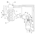
以下、この発明の一実施形態を図面に基づいて説明する。図1は、この実施形態のエンジンの排気ガス浄化装置の構成を概念的に示す模式図である。 Hereinafter, an embodiment of the present invention will be described with reference to the drawings. FIG. 1 is a schematic diagram conceptually showing the structure of an exhaust gas purification apparatus for an engine according to this embodiment.
図1に示すように、エンジン8の燃焼室1には、吸気通路3及び排気通路4が接続されている。燃焼室1には、吸気通路3を通じて空気が供給される。また、燃焼室1には、燃料噴射装置2によって燃料が噴射されるようになっている。燃焼室1からの排気ガスは、燃焼室1から引き出された排気通路4を通って送り出され、有害物質を除去する排気浄化部を通過した後に大気へ放出される。
As shown in FIG. 1, an intake passage 3 and an
燃焼室1へ通じる吸気通路3には、上流側から下流側に向かって、エアクリーナ、通路断面積を変化させて吸気の流量を制御するスロットルバルブ5、吸入空気量を検出するエアフローセンサ6等が順に設けられている。
The intake passage 3 leading to the combustion chamber 1 includes an air cleaner, a
排気通路4には、上流側から下流側に向かって、機械式過給機のタービン7、上流側の排気浄化部としてのディーゼル用酸化触媒装置10、還元剤を排気ガス中に噴射する還元剤インジェクタ20及びインパクタ22、還元剤を排気ガス中に分散させて均一化を図るミキサ30、還元剤又は還元剤から生成した物質によって排気ガス中の窒素酸化物を浄化する還元触媒本体13、消音装置としてのマフラ等が順に備えられている。
In the
還元剤インジェクタ20とインパクタ22、ミキサ30、還元触媒本体13等は、下流側の排気浄化部としての尿素選択触媒還元装置14を構成する。
The reducing
ディーゼル用酸化触媒装置10は、前後の排気通路4よりも大きな断面を有する空間をその内部に備え、その空間内には、担体としてハニカム構造の部材が収容されている。担体は、排気ガスが通過可能な多数のセルの集合を有している。その素材には、例えば、熱膨張率が小さく、耐熱衝撃性に優れた結晶質のセラミックス(コーディエライト組成)が用いられる。担体の表面には、触媒の機能を発揮するための金属が担持されている。これにより、通過する排気ガス中に含まれる一酸化炭素、炭化水素等の有害物質を、水や二酸化炭素等の無害な物質に浄化させることができる。
The diesel
上流側の排気浄化部を構成するディーゼル用酸化触媒装置10、下流側の排気浄化部である尿素選択触媒還元装置14は、いずれも、エンジン8の燃焼室1に近く、比較的高温の排気ガスに晒される機会が多い環境にある近接触媒として配置されている。
The diesel
インパクタ22は、排気通路4内の空間を、第一の空間27と第一の空間27の外部に形成される第二の空間26とに隔てる筒状の隔壁23を有するものとなっている。隔壁23は筒状であり、第二の空間26は、筒内の第一の空間27の外側全周を囲むように配置されている。特に、この実施形態では、排気通路4の内壁を構成する排気管壁部4aは断面円形であり、筒状の隔壁23も断面円形(円筒状)であり、両者が同心円状に配置されている。
The
還元剤インジェクタ20は、還元剤を、インパクタ22の隔壁23の内面に向かって噴射する。ここでは、還元剤として尿素(CO(NH2)2)を採用している。
The reducing
還元剤インジェクタ20による還元剤の噴射方向は、図1〜図3の各図に示すように、隔壁23の第一の空間27側の面に設定された噴射目標部28aを指向する。噴射目標部28aは、還元剤の噴射方向の噴射中心線pと、隔壁23の内面との交点である。
The reducing agent injection direction by the reducing
この実施形態では、隔壁23は、噴射目標部28aと還元剤インジェクタ20との間に、還元剤の導入孔23aを備えている。このため、噴射された還元剤は、導入孔23aを通じて第一の空間27内に侵入し、導入孔23aと還元剤インジェクタ20との間の第二の空間26内へは、ほとんど分散しないようになっている。
In this embodiment, the
また、噴射目標部28aと還元剤インジェクタ20との間には、噴射された還元剤を反射させて第一の空間27内に分散させる誘導部材24を備えている。このため、還元剤は、還元剤インジェクタ20側から噴射目標部28a側へと向かう噴射方向とは逆方向にも分散し、すなわち、噴射目標部28a側から還元剤インジェクタ20側へも拡がって、第一の空間27全体に均一に拡がるようになる。
In addition, a
また、還元剤の噴射中心線pは、図3に示すように、インパクタ22の上流側と下流側との間の排気ガスの流れ方向C、Dに交差し、特に、この実施形態では両者が直交しているので、還元剤の噴射方向を排気ガスの流れ方向と同じ方向(平行な方向)とする場合と比較して、還元触媒本体13に至るまでの間の還元剤の気化に要する時間や拡散に要する時間を相対的に長く確保しやすい。
Further, as shown in FIG. 3, the reducing agent injection center line p intersects the exhaust gas flow directions C and D between the upstream side and the downstream side of the impactor 22. Since they are orthogonal, the time required for vaporization of the reducing agent before reaching the reduction catalyst
さらに、隔壁23を隔てて内側の第一の空間27(誘導部材24よりも噴射目標部28a側の緩衝空間28を含む)、外側の第二の空間26のそれぞれに排気ガスが通過するので、隔壁23や誘導部材24等で構成されるインパクタ22は、排気通路4の内壁を構成する排気管壁部4aよりも温度が高くなる。排気管壁部4aは、その外面が外気に接するので、インパクタ22よりも相対的に温度が低いからである。
Furthermore, since the exhaust gas passes through the
還元剤である尿素は、水溶液の状態で還元剤インジェクタ20から噴射され、主として第一の空間27内の排気ガス中に飛散するとともに、その一部がインパクタ22に付着する。そして、尿素は、インパクタ22や排気ガスの高熱によって分解され、アンモニアを生成する。排気管壁部4aよりも高温であるインパクタ22に尿素が付着することから、その尿素のアンモニアへの分解が促進される。
Urea, which is a reducing agent, is injected from the reducing
ここで、隔壁23は、排気通路4の内壁を構成する排気管壁部4aに対して、隔壁23の素材よりも相対的に熱伝導率が低い素材で支持されている。図2に符号25で示す支持部材25が、この熱伝導率が低い素材で構成されている。これにより、インパクタ22の熱が、相対的に温度が低い排気管壁部4aに伝わることを抑制し、インパクタ22をより高い温度に維持しやすい。
Here, the
熱伝導率が低い素材とは、インパクタ22の素材である金属よりも相対的に熱が伝わりにくい素材、例えば、樹脂やゴム等を採用することができる。ただし、排気通路4の温度でも劣化や変質を起こさない耐熱性を有している素材に限られる。
As the material having a low thermal conductivity, a material that is relatively less likely to transmit heat than the metal that is the material of the impactor 22, such as a resin or rubber, can be employed. However, it is limited to a material having heat resistance that does not deteriorate or deteriorate even at the temperature of the
インパクタ22の熱が排気管壁部4aに伝わりにくくする手法としては、上記のような支持部材25の素材の特定以外にも、あるいは、それに加えて、支持部材25の形状を特定することによっても可能である。
As a method of making it difficult for the heat of the impactor 22 to be transmitted to the exhaust
例えば、支持部材25として、隔壁23と排気通路4の内壁とを結ぶ板状部材や軸状部材を採用することができる。板状部材の場合は、その面方向が隔壁23と排気通路4の内壁とを結ぶ方向に配置されることが望ましい。軸状部材の場合は、その軸方向が隔壁23と排気通路4の内壁とを結ぶ方向に配置されることが望ましい。板状部材や軸状部材は、同程度の一辺の長さを有するブロック状の部材よりもその体積が小さく、また、その板厚方向の端面や軸交差方向の断面が、隔壁23や排気通路4の内壁に接することで、互いの接触面積を小さくできるので、熱の伝導を抑制することができる。
For example, a plate-like member or a shaft-like member that connects the
また、この実施形態では、図2、図3及び図4(a)に示すように、誘導部材24は、還元剤の噴射方向に沿って、噴射目標部28aに近づくにつれて間隔が拡がる対の反射板24a,24aで構成されている。このため、噴射された還元剤は、平面視V字状に配置された対の反射板24a,24aに当たって反射して、図2に矢印Bで示すように、隔壁23の内面に沿って周方向へ流れて、第一の空間27全体に分散する。このため、還元剤の均一化が円滑である。
Further, in this embodiment, as shown in FIGS. 2, 3 and 4A, the
ここで、還元剤の噴射中心線pは、対の反射板24a,24aの接続部である稜線部24cに交差しているので、その稜線部24cを挟んで両側へ均等に還元剤を分散させることができる。
Here, since the injection center line p of the reducing agent intersects with the
また、対の反射板24aは、還元剤インジェクタ20側と噴射目標部28a側とを貫通する複数の通過孔24bを備えている。このため、図2に矢印Aで示すように、還元剤は、第一の空間27のうち、誘導部材24よりも噴射目標部28a側に位置する緩衝空間28へも、円滑に分散することができる。
Further, the pair of
ところで、還元剤インジェクタ20は一般に噴射の貫徹力が強く、噴射された還元剤は、特に、その噴射中心線p付近において、直進しようとする力が強い傾向がある。
Incidentally, the reducing
このため、対の反射板24a,24aに設けられる通過孔24bは、図4(a)に示すように、還元剤の噴射中心線pから遠ざかるにつれて、単位面積当たりの開口面積の合計が増加するように設定されている。このため、還元剤の噴射中心線p付近では、反射板24aによって反射する還元剤の割合を高くし、噴射中心線pから遠い付近では、直進する還元剤の割合を高く設定し、第一の空間27の全体において還元剤の分布を均一化することができる。
For this reason, as shown in FIG. 4A, the total opening area per unit area increases as the passage holes 24b provided in the pair of reflecting
図4(a)では、対の反射板24a,24aに設けられる通過孔24bを全て同じ形状(円形)且つ同じ断面積とし、単位面積当たりの通過孔24bの分布数を、対の反射板24a,24aを結ぶ稜線部24cから遠ざかるにつれて徐々に増加させる手法を採用している。図中の通過孔群Xよりも、通過孔群Yの方が、単位面積当たりの通過孔24bの分布数が多くなっている。これにより、還元剤の噴射中心線pから遠ざかるにつれて、単位面積当たりの開口面積の合計が増加する態様となっている。
In FIG. 4A, all of the passage holes 24b provided in the pair of
ここで、例えば、図4(b)に示すように、対の反射板24a,24aに設けられる通過孔24bを全て同じ形状(円形)としつつ、通過孔24bそれぞれの断面積を、対の反射板24a,24aを結ぶ稜線部24cから遠ざかるにつれて徐々に増加させる手法を採用することもできる。図中の通過孔群Xよりも、通過孔群Yの方が、さらには、通過孔群Zの方が、一つ当たりの通過孔24bの断面積が大きくなっている。この態様においても、還元剤の噴射中心線pから遠ざかるにつれて、単位面積当たりの開口面積の合計が増加する態様となっている。
Here, for example, as shown in FIG. 4B, the cross-sectional area of each of the passage holes 24b is made to be a pair of reflections while the passage holes 24b provided in the pair of
あるいは、通過孔24bによる単位面積当たりの開口面積の合計が、還元剤の噴射中心線pから遠ざかるにつれて放射状に増加するように設定してもよい。
Or you may set so that the sum total of the opening area per unit area by the
なお、誘導部材24に設けられる通過孔24bは、必要に応じて省略することもできる。ただし、噴射された還元剤の少なくとも一部が、誘導部材24よりも噴射目標部28a側の緩衝空間28に侵入するように、誘導部材24の位置や形状、還元剤インジェクタ20の位置や向きを設定することが望ましい。
Note that the
還元剤インジェクタ20は、排気通路4に開口する凹状のオフセット穴21内に設けられる。このため、還元剤インジェクタ20の噴射口は、排気通路4の内壁面よりもやや奥まった位置に配置される。このため、噴射口からインパクタ22の噴射目標部28aや誘導部材24までの噴射距離を長く確保でき、また、還元剤インジェクタ20を排気ガスの熱から保護することができる。さらに、還元剤インジェクタ20が排気ガスの流れを阻害しない。
The reducing
還元触媒本体13内やその付近では、還元触媒本体13が備える触媒の機能により、尿素から生成したアンモニアと、排気ガスに含まれる窒素酸化物とが反応し、窒素ガスと水が生成される。これにより、排気ガスが大気開放前に浄化される。
In the reduction catalyst
ここで、インパクタ22と還元触媒本体13との間にはミキサ30を備えているので、還元剤である尿素の排気ガス中への分散、均一化がさらに促進されている。このためアンモニアの発生、アンモニアと窒素酸化物との反応はさらに良好である。
Here, since the
例えば、ミキサ30として、図3に示すように、排気通路4の内面全周から内径側へ向かって突出する環状の突出片31を採用することができる。突出片31の内側への突出長さは、第二の空間26を通過する排気ガスの流速に応じて調整することができる。
For example, as shown in FIG. 3, an annular protruding
図3において、図中右側付近における第二の空間26を通過する排気ガスの流れCが、図中左側付近における第二の空間26を通過する排気ガスの流れCよりも速い場合を想定する。このような流速の差異は、図1に示すように、その上流側で排気通路4の形状が屈曲している等の事情によって生じ得る。屈曲部9の外方寄りを通過する流体は流速が速くなり、内方寄りを通過する流体は流速が遅くなる傾向がある。
In FIG. 3, it is assumed that the flow C of exhaust gas passing through the
このとき、図中に符号31aで示すように、流速が速い側に位置する突出片31の内側への突出長さを長くし、図中に符号31bで示すように、流速が遅い側に位置する突出片31の内径側への突出長さを短くすることが望ましい。また、流速が速い側と遅い側との間の中間部における突出長さは、符号31aの箇所に対応する最長突出長さと、符号31bの箇所に対応する最短突出長さの間の適切な長さに設定することができる。例えば、中間部における突出長さを、符号31aの箇所に対応する最長突出長さと、符号31bの箇所に対応する最短突出長さの平均値としてもよいし、あるいは、突出片の突出長さを、符号31aの最長突出長さの位置から符号31bの最短突出長さの位置まで、周方向に沿って連続的あるいは断続的に徐々に小さくなるように設定することもできる。
At this time, as indicated by
これにより、流速が速い側、遅い側のそれぞれにおいて、還元剤を多く含む第一の空間27を通過する排気ガスの流れDと、還元剤をほとんど含まない第二の空間26を通過する排気ガスの流れCとを衝突させ、排気通路4の断面全域に亘って還元剤をより均等に分散させることが可能となる。
As a result, the exhaust gas flow D passing through the
ただし、インパクタ22付近において、還元剤の排気ガス中への分散、均一化が充分に行われている場合には、ミキサ30を省略することも可能である。また、上記図3に示す例以外の他のミキサ30を用いることも可能である。
However, if the reducing agent is sufficiently dispersed and uniformed in the exhaust gas in the vicinity of the impactor 22, the
また、例えば、図5の変形例に示すように、還元剤インジェクタ20の噴射方向の噴射中心線pが、排気通路4内の排気ガスの流れ方向Cに対して、角度α(0<α<90度)をもって対向する方向としてもよい。この変形例においても、還元剤は、隔壁23の第一の空間27側の内面に設定された噴射目標部28aを指向している。また、還元剤は、誘導部材24に当たって反射することにより、第一の空間27全体に円滑に分散することができる。
Further, for example, as shown in the modification of FIG. 5, the injection center line p in the injection direction of the reducing
この場合、隔壁23に設けられる導入孔23aは省略することができる。また、誘導部材24に通過孔24bを設けてもよい点も同じである。
In this case, the
排気通路4には、図1に示すように、還元触媒本体13の上流側(入口付近)に、アンモニアの流入量の情報を取得するアンモニア検出部bを備えている。また、還元触媒本体13の下流側(出口付近)に、窒素酸化物の排出量の情報を取得する窒素酸化物検出部c、O2センサdが備えられている。さらに、ディーゼル用酸化触媒装置10の上流側(入口付近)には、排気ガスの温度を検出する排気ガス温度検出手段aを備えている。
As shown in FIG. 1, the
このエンジン8を搭載する車両は、電子制御ユニット(Electronic Control Unit)40を備えている。吸排気バルブや燃料噴射装置、その他エンジン8の動作に必要な機器、車両の各種装備等は、すべて電子制御ユニット40によって制御される。また、各種センサ類からの情報は、ケーブルを通じて電子制御ユニット40へ伝達される。
A vehicle equipped with the
電子制御ユニット40は、アンモニア検出部bによるアンモニアの流入量の情報と、窒素酸化物検出部cによる窒素酸化物の排出量の情報に基づいて、燃焼室1に供給される燃料の噴射量及び吸気の量を制御し、あるいは、噴射する還元剤の量や時期を制御するエンジン制御装置41を備えている。 Based on the information on the amount of inflow of ammonia by the ammonia detector b and the information on the amount of nitrogen oxide discharged by the nitrogen oxide detector c, the electronic control unit 40 An engine control device 41 that controls the amount of intake air or controls the amount and timing of the reducing agent to be injected is provided.
エンジン制御装置41は、これらの制御により、運転状態に応じて、還元触媒本体13の上流側で生成するアンモニアの量を制御することで、窒素酸化物の排出量を低減することができる。
With these controls, the engine control device 41 controls the amount of ammonia generated on the upstream side of the reduction catalyst
なお、上記の実施形態では、インパクタ22が備える隔壁23を円筒状として、断面円形の第一の空間27の外周全周に環状の第二の空間26を配置したが、この隔壁23として円筒状の部材以外、例えば、排気通路4の対向する内壁間を結ぶ板状部材を採用することもできる。
In the above embodiment, the
例えば、フラットな板状部材によって排気通路4の対向する内壁間を結ぶようにし、排気通路4内を、断面半円状の第一の空間27と同じく断面半円状の第二の空間26に隔てる構成とすることもできる。また、板状部材を設置する位置を適宜変更することによって、第一の空間27や第二の空間26の形状や互いの断面積、容積の比率を変更することもできる。
For example, the opposing inner walls of the
さらに、上記の実施形態では、誘導部材24として、平面視V字状に配置された対の反射板24a,24aを採用したが、この誘導部材24として平面視V字状以外、例えば、還元剤インジェクタ20側の面が円筒状に湾曲する、あるいは、球面状に湾曲する部材を採用することができる。ここで、誘導部材24の還元剤インジェクタ20側の面は、還元剤の噴射中心線pから遠ざかるにつれて噴射目標部28a側に近づく形状であることが望ましい。また、誘導部材24は、還元剤を反射させて第一の空間27全体に分散させるものであれば、対の反射板24a,24aのような板状部材のみならず、ブロック状の部材やフィン形状の部材の集合、網状部材等で構成することもできる。
Furthermore, in said embodiment, although the pair of reflecting
また、上記の実施形態では、還元剤として尿素を採用したが、尿素以外の還元剤を採用する場合にも、この発明を適用できる。例えば、還元剤としてアンモニアを採用し、そのアンモニアの水溶液等を噴射してもよい。 Moreover, although urea was employ | adopted as a reducing agent in said embodiment, this invention is applicable also when employ | adopting reducing agents other than urea. For example, ammonia may be employed as the reducing agent and an aqueous solution of the ammonia may be injected.
さらに、上記の実施形態では、上流側の排気浄化部であるディーゼル用酸化触媒装置10と下流側の排気浄化部である尿素選択触媒還元装置14をいずれも近接触媒としたが、これらをそれぞれ、エンジン8の燃焼室1から遠く、比較的高温の排気ガスに晒される機会が少ない環境にある床下触媒として配置する場合にもこの発明を適用できる。
Furthermore, in the above-described embodiment, the diesel
この実施形態では、ディーゼルエンジンにおける排気ガスの浄化について説明したが、この発明は、ディーゼルエンジン以外にも、排気ガス中への還元剤の噴射によって、その還元剤又はその還元剤から生成した物質によって、排気ガス中の窒素酸化物を浄化する還元触媒本体を備えたエンジン全般に用いることができる。 In this embodiment, the purification of exhaust gas in a diesel engine has been described. However, in addition to the diesel engine, the present invention is based on the reducing agent or a substance generated from the reducing agent by injection of the reducing agent into the exhaust gas. The engine can be used for all engines equipped with a reduction catalyst body that purifies nitrogen oxides in exhaust gas.
1 燃焼室
2 燃料噴射装置
3 吸気通路
4 排気通路
5 スロットルバルブ
6 エアフローセンサ
7 過給機
8 エンジン
10 ディーゼル用酸化触媒装置
13 還元触媒本体
14 尿素選択触媒還元装置
20 還元剤インジェクタ
21 オフセット穴
22 インパクタ
23 隔壁
23a 導入孔
24 誘導部材
24a 反射板
24b 通過孔
25 支持部材
26 第二の空間
27 第一の空間
28 緩衝空間
28a 噴射目標部
30 ミキサ
40 電子制御ユニット
41 エンジン制御装置
a 排気ガス温度検出手段
b アンモニア検出部
c 窒素酸化物検出部
d O2センサ
DESCRIPTION OF SYMBOLS 1
Claims (8)
前記排気通路内の排気ガス中に還元剤を噴射する還元剤インジェクタと、
前記還元剤又は前記還元剤から生成した物質によって前記排気ガス中の窒素酸化物を浄化する還元触媒本体と、
前記排気通路内を第一の空間と前記第一の空間の外部に形成される第二の空間とに隔てる隔壁を有するインパクタと、
を備え、
前記還元剤インジェクタによる前記還元剤の噴射方向は前記隔壁の前記第一の空間側の面に設定された噴射目標部を指向し、
前記噴射目標部と前記還元剤インジェクタとの間に前記還元剤を反射させて前記第一の空間内に分散させる誘導部材を備える
エンジンの排気ガス浄化装置。 An exhaust passage drawn from the combustion chamber of the engine;
A reducing agent injector for injecting a reducing agent into the exhaust gas in the exhaust passage;
A reduction catalyst main body for purifying nitrogen oxides in the exhaust gas by the reducing agent or a substance generated from the reducing agent;
An impactor having a partition wall separating the inside of the exhaust passage into a first space and a second space formed outside the first space;
With
The injection direction of the reducing agent by the reducing agent injector is directed to an injection target portion set on the surface of the partition on the first space side,
An exhaust gas purification apparatus for an engine, comprising an induction member that reflects and disperses the reducing agent in the first space between the injection target portion and the reducing agent injector.
前記隔壁は、前記噴射目標部と前記還元剤インジェクタとの間に前記還元剤の導入孔を備える
請求項1に記載のエンジンの排気ガス浄化装置。 The reducing agent injection direction is orthogonal to the flow direction of the exhaust gas between the upstream side and the downstream side of the impactor,
2. The engine exhaust gas purification device according to claim 1, wherein the partition includes an introduction hole for the reducing agent between the injection target portion and the reducing agent injector.
請求項1又は2に記載のエンジンの排気ガス浄化装置。 3. The engine exhaust gas according to claim 1, wherein the partition wall is supported by a material having a lower thermal conductivity than a material of the partition wall with respect to an exhaust pipe wall portion constituting an inner wall of the exhaust passage. Purification equipment.
請求項1〜3の何れか1項に記載のエンジンの排気ガス浄化装置。 The exhaust gas purification of an engine according to any one of claims 1 to 3, wherein the partition wall is supported via a plate-like member or a shaft-like member with respect to an exhaust pipe wall portion constituting an inner wall of the exhaust passage. apparatus.
請求項1〜4の何れか1項に記載のエンジンの排気ガス浄化装置。 The exhaust gas purification of an engine according to any one of claims 1 to 4, wherein the guide member is configured by a pair of reflecting plates whose intervals are increased as approaching the injection target portion along the injection direction of the reducing agent. apparatus.
請求項5に記載のエンジンの排気ガス浄化装置。 The engine exhaust gas purification device according to claim 5, wherein the pair of reflecting plates includes a plurality of passage holes penetrating the reducing agent injector side and the injection target portion side.
請求項6に記載のエンジンの排気ガス浄化装置。 The engine exhaust gas purification device according to claim 6, wherein the passage hole is set so that an opening area per unit area increases as the distance from the injection center line of the reducing agent increases.
請求項1〜7の何れか1項に記載のエンジンの排気ガス浄化装置。 The engine exhaust gas purification device according to any one of claims 1 to 7, further comprising a mixer between the impactor and the reduction catalyst main body.
Priority Applications (1)
| Application Number | Priority Date | Filing Date | Title |
|---|---|---|---|
| JP2017017639A JP2018123786A (en) | 2017-02-02 | 2017-02-02 | Exhaust emission control device |
Applications Claiming Priority (1)
| Application Number | Priority Date | Filing Date | Title |
|---|---|---|---|
| JP2017017639A JP2018123786A (en) | 2017-02-02 | 2017-02-02 | Exhaust emission control device |
Publications (1)
| Publication Number | Publication Date |
|---|---|
| JP2018123786A true JP2018123786A (en) | 2018-08-09 |
Family
ID=63110193
Family Applications (1)
| Application Number | Title | Priority Date | Filing Date |
|---|---|---|---|
| JP2017017639A Pending JP2018123786A (en) | 2017-02-02 | 2017-02-02 | Exhaust emission control device |
Country Status (1)
| Country | Link |
|---|---|
| JP (1) | JP2018123786A (en) |
-
2017
- 2017-02-02 JP JP2017017639A patent/JP2018123786A/en active Pending
Similar Documents
| Publication | Publication Date | Title |
|---|---|---|
| RU121371U1 (en) | EXHAUST GAS SAMPLER (OPTIONS) | |
| JP2018123788A (en) | Exhaust gas purification device | |
| KR101758217B1 (en) | Reducing agent mixing apparatus having liquid drop preventing function | |
| CN103547775B (en) | There is the close-coupled exhaust-gas treatment unit of mixed zone and the method for mix waste gas | |
| CN101779013B (en) | Exhaust purification apparatus | |
| US8440155B2 (en) | Flow modulating substrates for early light-off | |
| CN102374005B (en) | Engine emissions control system | |
| CN107407183B (en) | Exhaust gas purification unit | |
| US10385756B2 (en) | Exhaust device of engine | |
| CN105283641B (en) | The tilted perforations plate of radial inlet | |
| EP2386738A1 (en) | Compact reduction agent doser for use in an SCR system of an internal combustion engine | |
| JP2010513773A (en) | Mixing system for fluid injection and exhaust aftertreatment devices | |
| GB2512896A (en) | A mixer module and an emissions cleaning module | |
| JP4662334B2 (en) | Exhaust gas purification device for internal combustion engine | |
| JP5287988B2 (en) | Exhaust gas purification device for internal combustion engine | |
| JP2018131997A (en) | Exhaust emission control device | |
| JP7159465B2 (en) | catalytic converter | |
| US20140318111A1 (en) | Decomposition tube for an engine | |
| JP2018115586A (en) | Exhaust gas purification device | |
| JP2018123786A (en) | Exhaust emission control device | |
| JP4577099B2 (en) | Exhaust gas purification device for internal combustion engine | |
| JP2018123783A (en) | Exhaust gas purification device | |
| KR101283507B1 (en) | Apparatus for mixing reducing agent of scr system | |
| CN214247470U (en) | An exhaust system for an internal combustion engine | |
| JP5188477B2 (en) | Exhaust purification device |