JP2018131908A - EGR cooler - Google Patents
EGR cooler Download PDFInfo
- Publication number
- JP2018131908A JP2018131908A JP2017024011A JP2017024011A JP2018131908A JP 2018131908 A JP2018131908 A JP 2018131908A JP 2017024011 A JP2017024011 A JP 2017024011A JP 2017024011 A JP2017024011 A JP 2017024011A JP 2018131908 A JP2018131908 A JP 2018131908A
- Authority
- JP
- Japan
- Prior art keywords
- case
- egr cooler
- exhaust gas
- headers
- corners
- Prior art date
- Legal status (The legal status is an assumption and is not a legal conclusion. Google has not performed a legal analysis and makes no representation as to the accuracy of the status listed.)
- Pending
Links
- 239000000498 cooling water Substances 0.000 claims description 22
- 230000007423 decrease Effects 0.000 claims description 3
- 230000002950 deficient Effects 0.000 abstract description 4
- 239000002826 coolant Substances 0.000 abstract 1
- 239000007789 gas Substances 0.000 description 29
- 238000001816 cooling Methods 0.000 description 5
- MWUXSHHQAYIFBG-UHFFFAOYSA-N nitrogen oxide Inorganic materials O=[N] MWUXSHHQAYIFBG-UHFFFAOYSA-N 0.000 description 5
- 238000000034 method Methods 0.000 description 4
- 230000000052 comparative effect Effects 0.000 description 3
- 238000004519 manufacturing process Methods 0.000 description 2
- 239000013618 particulate matter Substances 0.000 description 2
- 238000002485 combustion reaction Methods 0.000 description 1
- 238000007599 discharging Methods 0.000 description 1
- 238000005516 engineering process Methods 0.000 description 1
- 239000000446 fuel Substances 0.000 description 1
- 238000012986 modification Methods 0.000 description 1
- 230000004048 modification Effects 0.000 description 1
- 230000008719 thickening Effects 0.000 description 1
Images


Landscapes
- Exhaust-Gas Circulating Devices (AREA)
- Details Of Heat-Exchange And Heat-Transfer (AREA)
Abstract
Description
本発明は、EGRクーラに関する。 The present invention relates to an EGR cooler.
本発明は、内燃機関の吸気系統に導入される排気ガスを冷却するためのEGRクーラに関する。 The present invention relates to an EGR cooler for cooling exhaust gas introduced into an intake system of an internal combustion engine.
近年、エンジンから排出される排気ガスに含まれる窒素酸化物(NOx)および粒子状物質(PM)等の低減や、エンジンの燃費向上を目的として、排気再循環(EGR:Exhaust Gas Recirculation)装置が広く用いられている。 In recent years, exhaust gas recirculation (EGR) devices have been developed for the purpose of reducing nitrogen oxides (NOx) and particulate matter (PM) contained in exhaust gas exhausted from engines and improving engine fuel efficiency. Widely used.
このようなEGR装置は、エンジンの排気ガスの再循環系に、排気ガスを冷却するEGRクーラを備えている。 Such an EGR device is provided with an EGR cooler for cooling the exhaust gas in the exhaust gas recirculation system of the engine.
EGRクーラは、例えば、扁平管にインナーフィンを挿入してロウ付けした複数のチューブユニットをケースに収容して構成されている。 The EGR cooler is configured, for example, by housing a plurality of tube units that are brazed by inserting inner fins into a flat tube.
ケースの外周部には冷却水入口管と冷却水出口管とが接続され、ケースの開口端部には排気ガス入口管と排気ガス出口管が接続されている。 A cooling water inlet pipe and a cooling water outlet pipe are connected to the outer periphery of the case, and an exhaust gas inlet pipe and an exhaust gas outlet pipe are connected to the opening end of the case.
冷却水入口管及び冷却水出口管と排気ガス入口管及び排気ガス出口管は、冷却水と排気ガスとが互いに並行して流通するように配置されている。 The cooling water inlet pipe, the cooling water outlet pipe, the exhaust gas inlet pipe, and the exhaust gas outlet pipe are arranged so that the cooling water and the exhaust gas flow in parallel with each other.
そして、冷却水入口管からケース内に流入した冷却水は、排気ガス入口管から排気ガス出口管に向かって各チューブユニット内を流通する排気ガスとの間で熱交換を行い、排気ガスを冷却した後、冷却水出口管から流されるようになっている。 The cooling water flowing into the case from the cooling water inlet pipe exchanges heat with the exhaust gas flowing through each tube unit from the exhaust gas inlet pipe toward the exhaust gas outlet pipe to cool the exhaust gas. After that, it is made to flow from the cooling water outlet pipe.
このようなEGRクーラに関する技術は種々提案されている(例えば、特許文献1等)。 Various techniques relating to such an EGR cooler have been proposed (for example, Patent Document 1).
特許文献1に係る従来技術では、プレス加工で成形したケースに、排気ガイド部を構成するヘッダを嵌合して取り付けている。 In the prior art according to Patent Document 1, a header constituting the exhaust guide portion is fitted and attached to a case formed by press working.
ところで、ケースおよびヘッダをプレス加工で成形する際には、角部に余肉が必然的に発生してしまう。 By the way, when the case and the header are formed by press working, extra corners are inevitably generated at the corners.
そのため、従来技術では、ケースにヘッダを嵌合させる際に、角部の余肉が邪魔をして、ヘッダを上手く嵌合することができず、良品の歩留まりが低下するという問題があった。 Therefore, in the prior art, when the header is fitted into the case, there is a problem in that the extra space at the corners interferes and the header cannot be fitted well, and the yield of non-defective products decreases.
本発明は、上記課題に鑑みてなされたものであり、ケースにヘッダを上手く嵌合することができ、良品の歩留まりを向上させることのできるEGRクーラを提供することを目的とする。 The present invention has been made in view of the above-described problems, and an object of the present invention is to provide an EGR cooler that can successfully fit a header to a case and improve the yield of non-defective products.
上記目的を達成するため、本発明に係るEGRクーラは、排気ガス通路を流れる排気ガスを冷却水との間で熱交換して冷却するEGRクーラであって、複数に亘って積層されるチューブユニットで構成される熱交換用コアと、前記熱交換用コアを収容するケースと、前記ケースの両端に形成される開口部に嵌合されるヘッダと、を備え、前記ケースの前記ヘッダ側の四隅の角部に、前記ケースの長手方向に延びる切込みが設けられていることを特徴とする。 In order to achieve the above object, an EGR cooler according to the present invention is an EGR cooler that cools exhaust gas flowing through an exhaust gas passage by exchanging heat with cooling water, and is a tube unit that is stacked in plural. A heat exchange core comprising: a case accommodating the heat exchange core; and headers fitted in openings formed at both ends of the case; and four corners on the header side of the case The corners are provided with cuts extending in the longitudinal direction of the case.
また、他の発明に係るEGRクーラは、排気ガス通路を流れる排気ガスを冷却水との間で熱交換して冷却するEGRクーラであって、複数に亘って積層されるチューブユニットで構成される熱交換用コアと、前記熱交換用コアを収容するケースと、前記ケースの両端に形成される開口部に嵌合されるヘッダと、を備え、前記ヘッダの前記ケース側の端部には、前記ケースの外縁側に向けて拡張される拡張部が設けられていることを特徴とする。 An EGR cooler according to another invention is an EGR cooler that cools exhaust gas flowing through an exhaust gas passage by exchanging heat with cooling water, and is configured by a plurality of tube units. A heat exchange core, a case that accommodates the heat exchange core, and a header that is fitted into openings formed at both ends of the case, and an end of the header on the case side includes: The expansion part extended toward the outer edge side of the said case is provided, It is characterized by the above-mentioned.
本発明によれば、ケースにヘッダを上手く嵌合することができ、良品の歩留まりを向上させることのできるEGRクーラを提供することができる。 ADVANTAGE OF THE INVENTION According to this invention, an EGR cooler which can fit a header into a case well and can improve the yield of a good article can be provided.
以下、本発明の一例としての実施の形態を図面に基づいて詳細に説明する。ここで、添付図面において同一の部材には同一の符号を付しており、また、重複した説明は省略されている。なお、ここでの説明は本発明が実施される最良の形態であることから、本発明は当該形態に限定されるものではない。 Hereinafter, an embodiment as an example of the present invention will be described in detail with reference to the drawings. Here, in the accompanying drawings, the same reference numerals are given to the same members, and duplicate descriptions are omitted. In addition, since description here is the best form by which this invention is implemented, this invention is not limited to the said form.
[実施の形態に係るEGRクーラ]
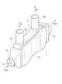
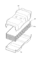
図1から図3を参照して、本実施の形態に係るEGRクーラ1の全体構成について説明する。
[EGR cooler according to the embodiment]
The overall configuration of the EGR cooler 1 according to the present embodiment will be described with reference to FIGS. 1 to 3.
EGRクーラ1は、例えば、扁平管にインナーフィンを挿入してロウ付けした複数のチューブユニットA1aから成る熱交換用コア(クーリングコア)A1を収容したケースCと、ケースCの両端側の開口部に嵌合されるヘッダ12、13等から構成されている。
The EGR cooler 1 includes, for example, a case C that houses a heat exchange core (cooling core) A1 composed of a plurality of tube units A1a that are brazed by inserting an inner fin into a flat tube, and openings on both ends of the case C. It is comprised from the
なお、ケースCは、図2に示すように互いに係合される2つのケース半体C1、C2とから構成されている(図2参照)。 The case C is composed of two case halves C1 and C2 that are engaged with each other as shown in FIG. 2 (see FIG. 2).
ケース半体C2の外周部には、冷却水がD1方向に流入する冷却水入口管101と、冷却水をD2方向に排出する冷却水出口管102が接続されている。
A cooling water inlet
ケースCの開口端部には、排気ガスをD10方向に導入する排気ガス入口管(図示せず)を接続するヘッダ12と、排気ガスをD11方向に排出する排気ガス出口管(図示せず)を接続するヘッダ13とがD22方向またはD23方向から嵌合されている(図3参照)。
A
なお、冷却水入口管101及び冷却水出口管102と、排気ガス入口管及び排気ガス出口管は、冷却水と排気ガスとが互いに並行して流通するように配置されている。
The cooling water inlet
そして、冷却水入口管101からD1方向にケースC内に流入した冷却水は、排気ガス入口管から排気ガス出口管に向かって(D10、D11方向)、チューブユニットA1内を流通する排気ガスとの間で熱交換を行い、排気ガスを冷却した後、冷却水出口管102からD2方向に排出されるようになっている。
The cooling water that has flowed into the case C in the direction D1 from the cooling
(ヘッダの比較例について)
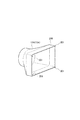
ここで、図4を参照して、EGRクーラに適用されるヘッダの比較例について説明する。
(About header comparison example)
Here, with reference to FIG. 4, the comparative example of the header applied to an EGR cooler is demonstrated.
図4に示す比較例に係るヘッダ12A、13Aは、プレス加工で成形する際に、角部に余肉(増肉部)201が必然的に発生してしまう。
When the
そのため、図3に示すように、ケースCの端部251、252に対してヘッダ12A、13AをD22方向またはD23方向から嵌合させる際に、角部の余肉201が邪魔をしてしまう。そのため、ヘッダ12A、13AをケースCの端部251、252に上手く嵌合することができず、良品の歩留まりが低下するという不都合があった。
Therefore, as shown in FIG. 3, when the
(ケースの第1実施例について)
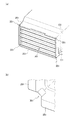
図5を参照して、本実施の形態に係るEGRクーラ1に適用されるケースC(C1、C2)の第1実施例について説明する。
(About the first embodiment of the case)
A first example of case C (C1, C2) applied to EGR cooler 1 according to the present embodiment will be described with reference to FIG.
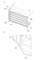
ここで、図5(a)は、実施の形態に係るEGRクーラ1に適用されるケースCの第1実施例を示す斜視図、図5(b)は、その要部の拡大図である。 Here, Fig.5 (a) is a perspective view which shows the 1st Example of case C applied to the EGR cooler 1 which concerns on embodiment, FIG.5 (b) is an enlarged view of the principal part.
図5(a)、(b)に示すように、第1実施例では、ケースC(C1、C2)のヘッダ側の四隅の角部に、ケースの長手方向に延びる切込み301が設けられている。
As shown in FIGS. 5A and 5B, in the first embodiment,
切込み301は、図5(b)に示すように、先端部から根元部に向けて切込み幅は略一様(略等幅)となるように形成されている。
As shown in FIG. 5 (b), the
これにより、図3に示すように、ケースCの端部251、252にヘッダ12、13を嵌合する際に、ヘッダ12、13の内側の隅部(角部)に、図4に示すのと同様に余肉(増肉部)201が形成された場合であっても、ケースC(C1、C2)のヘッダ側の四隅の角部に形成された切込み301によって余肉201による干渉を避けることができ、ケースCまたはヘッダ12、13に歪みが生じる事態を回避することができる。
Thus, as shown in FIG. 3, when the
したがって、ケースCにヘッダ12、13を上手く嵌合することができ、良品の歩留まりを向上させることができる。
Therefore, the
(ケースの第2実施例について)
図6を参照して、本実施の形態に係るEGRクーラ1に適用されるケースC(C1、C2)の第2実施例について説明する。
(About the second embodiment of the case)
A second example of case C (C1, C2) applied to EGR cooler 1 according to the present embodiment will be described with reference to FIG.
ここで、図6(a)は、実施の形態に係るEGRクーラ1に適用されるケースCの第2実施例を示す斜視図、図6(b)は、その要部の拡大図である。 Here, Fig.6 (a) is a perspective view which shows the 2nd Example of case C applied to the EGR cooler 1 which concerns on embodiment, FIG.6 (b) is an enlarged view of the principal part.
図6(a)、(b)に示すように、第1実施例では、ケースC(C1、C2)のヘッダ側の四隅の角部に、ケースの長手方向に延びる切込み302が設けられている。
As shown in FIGS. 6A and 6B, in the first embodiment,
切込み302は、図6(b)に示すように、先端部から根元部に向けて切込み幅が徐々に狭くなるように、即ち、略三角形状を呈するように形成されている。
As shown in FIG. 6B, the
これにより、図3に示すように、ケースCの端部251、252にヘッダ12、13を嵌合する際に、ヘッダ12、13の内側の隅部(角部)に、図4に示すのと同様に余肉(増肉部)201が形成された場合であっても、ケースC(C1、C2)のヘッダ側の四隅の角部に形成された切込み301によって余肉201による干渉を避けるようにガイドして嵌合させることができ、ケースCまたはヘッダ12、13に歪みが生じる事態を回避することができる。
Thus, as shown in FIG. 3, when the
したがって、ケースCにヘッダ12、13を上手く嵌合することができ、良品の歩留まりを向上させることができる。
Therefore, the
(ヘッダの第1実施例について)
図7および図8を参照して、実施の形態に係るEGRクーラ1に適用されるヘッダ12、13の第1実施例について説明する。
(About the first embodiment of the header)
A first example of
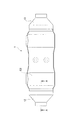
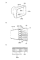
ここで、図7は、実施の形態に係るEGRクーラ1の全体構成を示す平面図、図8(a)は実施の形態に係るEGRクーラ1に適用されるヘッダ12、13の第1実施例を示す斜視図、図8(b)は図7のA−A線断面図、図8(c)は要部の拡大図である。
7 is a plan view showing the overall configuration of the EGR cooler 1 according to the embodiment, and FIG. 8A is a first example of
第1実施例に係るヘッダ12、13では、ヘッダ12、13のケースC側の端部200に、ケースCの外縁側に向けて拡張される拡張部200aが設けられている。
In the
そして、図8(b)、(c)に示すように、拡張部200aは、端部にR加工を施したピンチトリム形状とされている。
And as shown to FIG.8 (b), (c), the
これにより、図3に示すように、ケースCの端部251、252にヘッダ12、13を嵌合する際に、ヘッダ12、13の内側の隅部(角部)に、図4に示すのと同様に余肉(増肉部)201が形成された場合であっても、ヘッダ12、13のケースC側の端部200にピンチトリム形状の拡張部200aが設けられているので、余肉201による干渉を避けるようにガイドして嵌合させることができ、ケースCまたはヘッダ12、13に歪みが生じる事態を回避することができる。
Thus, as shown in FIG. 3, when the
したがって、ケースCにヘッダ12、13を上手く嵌合することができ、良品の歩留まりを向上させることができる。
Therefore, the
なお、前述のケースCの第1実施例、第2実施例と同様に、ケースC側に切込み301、302を設けるようにしてもよい。
Note that the
これにより、よりスムーズにケースCとヘッダ12、13との嵌合を行うことができる。
Thereby, fitting with case C and
(ヘッダの第2実施例について)
図9を参照して、実施の形態に係るEGRクーラ1に適用されるヘッダ12、13の第2実施例について説明する。
(Regarding the second embodiment of the header)
With reference to FIG. 9, the 2nd Example of the
ここで、図9(a)は実施の形態に係るEGRクーラ1に適用されるヘッダ12、13の第2実施例を示す斜視図、図9(b)は図7のA−A線断面図、図9(c)は要部の拡大図である。
Here, FIG. 9A is a perspective view showing a second example of the
第2実施例に係るヘッダ12、13では、ヘッダ12、13のケースC側の端部200に、ケースCの外縁側に向けて拡張される拡張部200bが設けられている。
In the
そして、図9(b)、(c)に示すように、拡張部200bは、端部が比較的大きく広がるラッパ形状とされている。
And as shown to FIG.9 (b), (c), the
これにより、図3に示すように、ケースCの端部251、252にヘッダ12、13を嵌合する際に、ヘッダ12、13の内側の隅部(角部)に、図4に示すのと同様に余肉(増肉部)201が形成された場合であっても、ヘッダ12、13のケースC側の端部200にラッパ形状の拡張部200bが設けられているので、余肉201による干渉を避けるようにガイドして嵌合させることができ、ケースCまたはヘッダ12、13に歪みが生じる事態を回避することができる。
Thus, as shown in FIG. 3, when the
したがって、ケースCにヘッダ12、13を上手く嵌合することができ、良品の歩留まりを向上させることができる。
Therefore, the
なお、前述のケースCの第1実施例、第2実施例と同様に、ケースC側に切込み301、302を設けるようにしてもよい。
Note that the
これにより、よりスムーズにケースCとヘッダ12、13との嵌合を行うことができる。
Thereby, fitting with case C and
以上本発明者によってなされた発明を実施の形態に基づき具体的に説明したが、本明細書で開示された実施の形態はすべての点で例示であって開示された技術に限定されるものではないと考えるべきである。すなわち、本発明の技術的な範囲は、前記の実施の形態における説明に基づいて制限的に解釈されるものでなく、あくまでも特許請求の範囲の記載にしたがって解釈すべきであり、特許請求の範囲の記載技術と均等な技術および特許請求の範囲内でのすべての変更が含まれる。 Although the invention made by the present inventor has been specifically described based on the embodiments, the embodiments disclosed herein are illustrative in all respects and are not limited to the disclosed technology. Should not be considered. That is, the technical scope of the present invention should not be construed restrictively based on the description in the above embodiment, but should be construed according to the description of the scope of claims. All the modifications within the scope of the claims and the equivalent technique to the described technique are included.
1…EGRクーラ
12,13…ヘッダ
200…端部
200a、200b…拡張部
201…余肉(増肉部)
301、302…切込み
A1…熱交換用コア(クーリングコア)
A1a…チューブユニット
C(C1,C2)…ケース
DESCRIPTION OF SYMBOLS 1 ...
301, 302 ... cut A1 ... core for heat exchange (cooling core)
A1a ... Tube unit C (C1, C2) ... Case
Claims (6)
複数に亘って積層されるチューブユニットで構成される熱交換用コアと、
前記熱交換用コアを収容するケースと、
前記ケースの両端に形成される開口部に嵌合されるヘッダと、
を備え、
前記ケースの前記ヘッダ側の四隅の角部に、前記ケースの長手方向に延びる切込みが設けられていることを特徴とするEGRクーラ。 An EGR cooler that cools exhaust gas flowing through an exhaust gas passage by exchanging heat with cooling water,
A core for heat exchange composed of a plurality of tube units stacked,
A case for housing the heat exchange core;
Headers fitted into openings formed at both ends of the case;
With
An EGR cooler characterized in that cuts extending in the longitudinal direction of the case are provided at corners of the four corners on the header side of the case.
複数に亘って積層されるチューブユニットで構成される熱交換用コアと、
前記熱交換用コアを収容するケースと、
前記ケースの両端に形成される開口部に嵌合されるヘッダと、
を備え、
前記ヘッダの前記ケース側の端部には、前記ケースの外縁側に向けて拡張される拡張部が設けられていることを特徴とするEGRクーラ。 An EGR cooler that cools exhaust gas flowing through an exhaust gas passage by exchanging heat with cooling water,
A core for heat exchange composed of a plurality of tube units stacked,
A case for housing the heat exchange core;
Headers fitted into openings formed at both ends of the case;
With
An EGR cooler characterized in that an extension portion that extends toward an outer edge side of the case is provided at an end of the header on the case side.
Priority Applications (1)
| Application Number | Priority Date | Filing Date | Title |
|---|---|---|---|
| JP2017024011A JP2018131908A (en) | 2017-02-13 | 2017-02-13 | EGR cooler |
Applications Claiming Priority (1)
| Application Number | Priority Date | Filing Date | Title |
|---|---|---|---|
| JP2017024011A JP2018131908A (en) | 2017-02-13 | 2017-02-13 | EGR cooler |
Publications (1)
| Publication Number | Publication Date |
|---|---|
| JP2018131908A true JP2018131908A (en) | 2018-08-23 |
Family
ID=63247449
Family Applications (1)
| Application Number | Title | Priority Date | Filing Date |
|---|---|---|---|
| JP2017024011A Pending JP2018131908A (en) | 2017-02-13 | 2017-02-13 | EGR cooler |
Country Status (1)
| Country | Link |
|---|---|
| JP (1) | JP2018131908A (en) |
Cited By (1)
| Publication number | Priority date | Publication date | Assignee | Title |
|---|---|---|---|---|
| US20240159477A1 (en) * | 2021-03-17 | 2024-05-16 | Valeo Autosystemy Sp. Z O.O. | Heat exchanger |
-
2017
- 2017-02-13 JP JP2017024011A patent/JP2018131908A/en active Pending
Cited By (1)
| Publication number | Priority date | Publication date | Assignee | Title |
|---|---|---|---|---|
| US20240159477A1 (en) * | 2021-03-17 | 2024-05-16 | Valeo Autosystemy Sp. Z O.O. | Heat exchanger |
Similar Documents
| Publication | Publication Date | Title |
|---|---|---|
| US10202880B2 (en) | Exhaust heat exchanger | |
| US6595274B2 (en) | Exhaust gas heat exchanger | |
| JP5850693B2 (en) | Tube for heat exchanger | |
| US7077190B2 (en) | Exhaust gas heat exchanger | |
| US7204302B2 (en) | Exhaust gas heat exchanger | |
| EP2917550B1 (en) | Heat exchange device for exchanging heat between fluids | |
| US20070193732A1 (en) | Heat exchanger | |
| KR20080088328A (en) | Heat exchanger and method | |
| US7774937B2 (en) | Heat exchanger with divided coolant chamber | |
| KR101793752B1 (en) | Heat exchanger for gases, in particular for the exhaust gases of an engine | |
| US9915481B2 (en) | Fin for heat exchanger | |
| JP6619675B2 (en) | Channel structure | |
| JP5511917B2 (en) | Assembly structure of plate fin type heat exchanger and manufacturing method of plate fin type heat exchanger | |
| WO2017122832A1 (en) | Exhaust gas heat exchanger having stacked flat tubes | |
| CN115176120A (en) | Heat exchanger | |
| US11454460B2 (en) | Exhaust gas recirculation heat exchanger assembly | |
| JP2003090693A (en) | Exhaust heat exchanger | |
| JP5903911B2 (en) | Heat exchanger | |
| WO2015107814A1 (en) | Heat transfer pipe for heat exchanger and heat exchanger | |
| JP6463993B2 (en) | Tube for heat exchanger | |
| JP2009222306A (en) | Unit core for plate fin type heat exchanger, assembly structure of heat exchanger using the unit core and method for manufacturing heat exchanger | |
| JP6789019B2 (en) | Corrugated fins and heat exchanger | |
| JP2007017061A (en) | Gas cooler for carbon dioxide air conditioner | |
| JP2018131929A (en) | Egr cooler and manufacturing method of the same | |
| JP2015190697A (en) | EGR cooler |