JP2018136102A - Heat exchanger - Google Patents
Heat exchanger Download PDFInfo
- Publication number
- JP2018136102A JP2018136102A JP2017031844A JP2017031844A JP2018136102A JP 2018136102 A JP2018136102 A JP 2018136102A JP 2017031844 A JP2017031844 A JP 2017031844A JP 2017031844 A JP2017031844 A JP 2017031844A JP 2018136102 A JP2018136102 A JP 2018136102A
- Authority
- JP
- Japan
- Prior art keywords
- heat exchanger
- refrigerant
- temperature
- header
- hot gas
- Prior art date
- Legal status (The legal status is an assumption and is not a legal conclusion. Google has not performed a legal analysis and makes no representation as to the accuracy of the status listed.)
- Granted
Links
Images

Landscapes
- Details Of Heat-Exchange And Heat-Transfer (AREA)
- Heat-Exchange Devices With Radiators And Conduit Assemblies (AREA)
Abstract
【課題】扁平管熱交換器でも、従来のフィンアンドチューブ型熱交換器と同様に、ホットガスバイパス管を液側冷媒配管に接続し、圧縮機から吐出された高温高圧の冷媒の一部を流して、暖房運転中に熱交換器に付着した霜を融かす方法が考えられる。しかし、冷媒がヘッダ内の絞り部で減圧されると温度が−5℃〜0℃にまで低下してしまい、室外熱交換器に付着した霜を融かすまでの温度の冷媒が得られなかった。そこで、本発明は、ホットガスバイパス管を介して流入した高温高圧の冷媒により付着した霜を融かせるようにした熱交換器を提供することを目的とする。【解決手段】ヘッダの内部は、冷媒を整流する整流部と、伝熱管に冷媒を分流する分流部とに仕切られ、整流部には、整流部から流出する冷媒の流速を上げる絞り部が設けられ、分流部には、ホットガスバイパス管が接続されるバイパス接続部を有する熱交換を提供する。【選択図】図2PROBLEM TO BE SOLVED: To connect a hot gas bypass pipe to a liquid-side refrigerant pipe in a flat tube heat exchanger as in a conventional fin-and-tube heat exchanger, and to connect a part of a high-temperature and high-pressure refrigerant discharged from a compressor. A method of flowing the gas to melt the frost adhering to the heat exchanger during the heating operation can be considered. However, when the refrigerant was decompressed at the throttle in the header, the temperature dropped to -5 ° C to 0 ° C, and it was not possible to obtain a refrigerant with a temperature sufficient to melt the frost adhering to the outdoor heat exchanger. .. Therefore, an object of the present invention is to provide a heat exchanger capable of melting the frost adhering to the high-temperature and high-pressure refrigerant flowing in through the hot gas bypass pipe. SOLUTION: The inside of a header is divided into a rectifying section for rectifying the refrigerant and a diversion section for shunting the refrigerant into a heat transfer tube, and the rectifying section is provided with a throttle section for increasing the flow velocity of the refrigerant flowing out from the rectifying section. The diversion section provides heat exchange with a bypass connection to which the hot gas bypass tube is connected. [Selection diagram] Fig. 2
Description
本発明は、伝熱管とフィンとヘッダを備え、伝熱管内を流れる流体を空気と熱交換させる熱交換器に関するものである。 The present invention relates to a heat exchanger that includes a heat transfer tube, fins, and a header, and exchanges heat between fluid flowing in the heat transfer tube and air.
空気調和機の冷媒回路では、暖房運転時に圧縮機、四方弁、室内熱交換器、膨張弁、室外熱交換器、四方弁、圧縮機と順に冷媒が流れるよう冷媒配管が接続されている。この冷媒回路の中には、圧縮機と四方弁を繋ぐ冷媒配管から高温高圧の冷媒を一部分岐させて、分岐された高温高圧の冷媒を膨張弁と室外熱交換器とを繋ぐ液側冷媒配管に流入させるホットガスバイパス管を備えたものがある。このホットガスバイパス管は、暖房運転中に室外熱交換器に付着した霜を融かすためのものである。(特許文献1参照) In the refrigerant circuit of the air conditioner, refrigerant piping is connected so that the refrigerant flows in the order of the compressor, the four-way valve, the indoor heat exchanger, the expansion valve, the outdoor heat exchanger, the four-way valve, and the compressor during the heating operation. In this refrigerant circuit, a liquid side refrigerant pipe that partially branches a high-temperature and high-pressure refrigerant from a refrigerant pipe that connects the compressor and the four-way valve, and that connects the branched high-temperature and high-pressure refrigerant to the expansion valve and the outdoor heat exchanger. Some have hot gas bypass pipes that flow into the pond. This hot gas bypass pipe is for melting frost adhering to the outdoor heat exchanger during heating operation. (See Patent Document 1)
この室外熱交換器が扁平管とヘッダを備えた扁平管熱交換器であった場合、扁平管熱交換器の両側に備えられるヘッダに冷媒が流出入する。室外熱交換器が蒸発器として機能する暖房運転の場合、ヘッダの下部に接続された液側冷媒配管より中温中圧の冷媒が流入する。この中温中圧の冷媒は温度が−5℃〜0℃の低温低圧の冷媒よりも温度と圧力が少しだけ高い、温度が5℃〜15℃の冷媒である。ヘッダの内部は、流入した中温中圧の冷媒を整流し各扁平管へ均一に分流するために、液側冷媒配管が接続される整流部と、扁平管が接続される分流部に仕切られている。整流部には通過する冷媒を減圧して流速を上げる絞り部が設けられ、この絞り部はヘッダの内部を仕切る仕切板の中心に形成された孔部がその機能を果たす。整流部に流入した冷媒はこの絞り部で絞られることで流速が上がり分流部の上端にまで届くことができ、分流部内を2相冷媒が均一に満たす状態にすることができる。 When this outdoor heat exchanger is a flat tube heat exchanger having a flat tube and a header, the refrigerant flows into and out of the headers provided on both sides of the flat tube heat exchanger. In the heating operation in which the outdoor heat exchanger functions as an evaporator, medium-temperature and medium-pressure refrigerant flows from the liquid-side refrigerant pipe connected to the lower part of the header. This medium temperature / medium pressure refrigerant is a refrigerant having a temperature of 5 ° C. to 15 ° C. that is slightly higher in temperature and pressure than a low temperature / low pressure refrigerant having a temperature of −5 ° C. to 0 ° C. The inside of the header is divided into a rectifying unit to which the liquid side refrigerant pipe is connected and a diverting unit to which the flat tube is connected in order to rectify the medium-temperature and medium-pressure refrigerant that has flowed in and uniformly distribute it to each flat tube. Yes. The rectifying unit is provided with a throttle part that depressurizes the refrigerant passing therethrough to increase the flow velocity, and this throttle part functions as a hole formed at the center of the partition plate that partitions the inside of the header. The refrigerant that has flowed into the rectifying unit is throttled by the throttle unit, so that the flow velocity increases and can reach the upper end of the branching unit, so that the two-phase refrigerant can be uniformly filled in the branching unit.
この扁平管熱交換器でも、従来のフィンアンドチューブ型熱交換器と同様に、ホットガスバイパス管を液側冷媒配管に接続し、圧縮機から吐出された高温高圧の冷媒の一部を流して、暖房運転中に熱交換器に付着した霜を融かす方法が考えられる。この方法を実施した場合について説明する。 In this flat tube heat exchanger as well as the conventional fin-and-tube heat exchanger, the hot gas bypass pipe is connected to the liquid side refrigerant pipe and a part of the high-temperature and high-pressure refrigerant discharged from the compressor is allowed to flow. A method of melting frost attached to the heat exchanger during the heating operation can be considered. The case where this method is implemented will be described.
ホットガスバイパス管を介して流入する温度が20℃〜40℃の高温高圧の冷媒は液側冷媒配管を流れる温度が5℃〜15℃の中温中圧の冷媒と混ざり、温度が5℃〜20℃に低下する。この冷媒がヘッダ内の絞り部で減圧されると温度が−5℃〜0℃にまで低下してしまい、室外熱交換器に付着した霜を融かすまでの温度の冷媒が得られなかった。 The high-temperature and high-pressure refrigerant having a temperature flowing in through the hot gas bypass pipe is mixed with the medium- and medium-pressure refrigerant having a temperature flowing through the liquid side refrigerant pipe of 5 ° C to 15 ° C, and the temperature is 5 ° C to 20 ° C. Decrease to ℃. When this refrigerant was depressurized at the throttle in the header, the temperature dropped to −5 ° C. to 0 ° C., and a refrigerant having a temperature until the frost adhered to the outdoor heat exchanger was melted could not be obtained.
そこで、本発明は、ホットガスバイパス管を介して流入した高温高圧の冷媒により付着した霜を融かせるようにした熱交換器を提供することを目的とする。 Then, an object of this invention is to provide the heat exchanger which melt | dissolved the frost adhering with the high temperature / high pressure refrigerant | coolant which flowed in via the hot gas bypass pipe.
上述した問題を解決するために、本発明は、上下に配列される複数の伝熱管と、前記複数の伝熱管と交差し、左右に配列される板状の複数のフィンと、前記複数の伝熱管の端部に接続された管状のヘッダを有する熱交換器であって、前記ヘッダの内部は、冷媒を整流する整流部と、前記伝熱管に冷媒を分流する分流部とに仕切られ、前記整流部には、前記整流部から流出する冷媒の流速を上げる絞り部が設けられ、前記分流部には、ホットガスバイパス管が接続されるバイパス管接続部を有することを特徴とする。 In order to solve the above-described problem, the present invention provides a plurality of heat transfer tubes arranged vertically, a plurality of plate-like fins intersecting with the plurality of heat transfer tubes and arranged on the left and right, and the plurality of heat transfer tubes. A heat exchanger having a tubular header connected to an end of a heat pipe, wherein the inside of the header is partitioned into a rectifying part for rectifying the refrigerant and a diversion part for diverting the refrigerant to the heat transfer pipe, The rectifying part is provided with a throttle part for increasing the flow rate of the refrigerant flowing out from the rectifying part, and the diversion part has a bypass pipe connecting part to which a hot gas bypass pipe is connected.
また、前記バイパス管接続部が前記絞り部の近傍に設けられることを特徴とする。 Further, the bypass pipe connecting portion is provided in the vicinity of the throttle portion.
本発明の熱交換器によれば、ホットガスバイパス管を分流部に接続するため、ホットガスバイパス管から流入する高温高圧の冷媒が絞り部で減圧されず、高温のまま分流部に流入するので室外熱交換器に付着した霜を融かすことができる。 According to the heat exchanger of the present invention, since the hot gas bypass pipe is connected to the flow dividing section, the high-temperature and high-pressure refrigerant flowing from the hot gas bypass pipe is not decompressed by the throttle section and flows into the flow dividing section at a high temperature. Frost adhering to the outdoor heat exchanger can be melted.
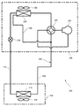
本発明の実施形態に関する熱交換器100は、空気調和機200に設けられた室外熱交換器330である。以下に本発明の実施形態に係る熱交換器100を備えた空気調和機200について、図4を基に以下に説明する。図4は、本発明にかかる空気調和機の冷媒回路を示した図である。
The
空気調和機200は室外機300と室内機400を備えている。室外機300と室内機400は液側冷媒配管510とガス側冷媒配管520を介して互いに接続されている。空気調和機200では、室外機300と、室内機400と、液側冷媒配管510と、ガス側冷媒配管520によって、冷媒回路600が形成される。
The
冷媒回路600には、圧縮機310と、四方弁320と、室外熱交換器330と、膨張弁340と、室内熱交換器410とが設けられている。圧縮機310と四方弁320と室外熱交換器330と膨張弁340は室外機300に収容されている。室内熱交換器410は室内機400に収容されている。また、室外機300には外気を室外機300の内部に取り込み、室外熱交換器330で冷媒と熱交換された空気を室外機300の外に吹き出すための室外ファン350が設けられている。室内機400には室内の空気を室内機400の内部に取り込み、室内熱交換器410で生成された調和空気を室内に吹き出すための室内ファン420が設けられている。
The
空気調和機200は冷房運転と暖房運転を選択的に行える。冷房運転中の冷媒回路600では、圧縮機310、四方弁320、室外熱交換器330、膨張弁340、室内熱交換器410、四方弁320、圧縮機310の順に冷媒が循環する。この時、室外熱交換器330は凝縮器として機能し、室内熱交換器410は蒸発器として機能する。一方、暖房運転中の冷媒回路600では、圧縮機310、四方弁320、室内熱交換器410、膨張弁340、室外熱交換器330、四方弁320、圧縮機310の順に冷媒が循環する。この時、室外熱交換器330は蒸発器として機能し、室内熱交換器410は凝縮器として機能する。
The
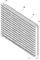
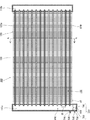
本発明の実施形態に関する熱交換器100は、図1と図2に示すように、フィン120と扁平管130と第1ヘッダ110aと第2ヘッダ110bを備えた扁平管熱交換器である。図1は、本発明にかかる熱交換器100の全体を示した斜視図である。図2は、本発明にかかる熱交換器100の全体を示した正面図である。図3は、図2の切断線A−Aにおける断面図である。
The
図1と図2に示すように、熱交換器100は、第1ヘッダ110aと、第2ヘッダ110bと、複数の扁平管130と、複数のフィン120とを備えている。第1ヘッダ110a、第2ヘッダ110b、扁平管130、フィン120はいずれもアルミニウム合金製の部材であり、各々の接合は蝋付けによって行われている。
As shown in FIGS. 1 and 2, the
扁平管130は多孔構造であり、断面形状が長円形あるいは角の丸い矩形となった伝熱管であり、後述するフィン120と直交する方向に延びている。扁平管130には冷媒が流れる冷媒流路が複数本配置されており、この冷媒流路は扁平管130の長手方向の一端と他端の間に、長手方向の一端から他端にかけて延びて形成され、扁平管130の短手方向に等間隔で配置されている。熱交換器100において、各扁平管130は、各々の上側の面と下側の面が対向するように、熱交換器100の熱交換能力と通風抵抗などを考慮して決定した間隔である第1の間隔d1をおいて上下に並んで配置されている。各扁平管130は、一端が第1ヘッダ110aに挿入され、他端が第2ヘッダ110bに挿入されている。なお、扁平管130の長手方向を左右方向とする。
The
フィン120は、金属板をプレス加工することによって、縦長の板形状に形成されている。フィン120には、図3に示すように、フィン120の短手方向の一端からフィン120の短手方向(前後方向)の他端に向かって延びる横長の切り欠き部140が、フィン120の長手方向(上下方向)に所定の間隔をおいて多数形成されている。この切り欠き部140に扁平管130が差し込まれることで、扁平管130は上下方向に第1の間隔d1をおいて配置される。また、フィン120は、図1に示すように、扁平管130の長手方向(左右方向)に熱交換器100の熱交換能力と通風抵抗などを考慮して決定した間隔である第2の間隔d2をおいて複数枚配置される。図2に示すように、上下に隣り合う扁平管130と、左右に隣り合うフィン120に囲まれた通風路150が、上下方向と左右方向それぞれに複数並んで形成される。なお、図2では複数の通風路150のうち1つを代表して図示している。フィン120と扁平管130は互いに直交しており、図3に示すように、フィン120の表面のうち、複数の通風路の一つと接すると共に、上下に隣り合う扁平管130の間に位置する面が、矢印Fで示す空気と熱交換する伝熱部121となる。また、フィン120の一部で切欠き部140よりフィン120の他端側にある面が、フィン120の上端120aから下端120bまで連続して形成された流水部(連通部)122となる。なお、矢印Fがある側を風上側、反対側を風下側とする。また、本実施例では流水部(連通部)122をフィン120の風下側に形成しているが、本発明はこれに限定したものではなく、風上側に形成してもよい。
The
第1ヘッダ110aと第2ヘッダ110bは、両方とも長手方向の両端が閉鎖された細長い管状に形成されている。熱交換器100の一端側に第1ヘッダ110aが配置され、熱交換器100の他端側に第2ヘッダ110bが配置される。なお、第1ヘッダ110aと第2ヘッダ110bのそれぞれの長手方向を熱交換器100の上下方向とする。第1ヘッダ110aの内部の下部には仕切板700が設けられ、この仕切板700によって内部が分流部810と整流部820の二つに仕切られている。分流部810は複数の扁平管130に冷媒を均一に分流する。整流部820は熱交換器100が蒸発器として機能した時に、冷媒が最初に流入し、流入した冷媒を整流する部分である。仕切板700の中心には絞り部として機能する孔部710が形成されている。整流部820から流出する冷媒はこの孔部710を通過することにより減圧され流速が上がる。これにより、冷媒は分流部810に勢いよく流出し、分流部810が2相冷媒で均一に満たされる。さらに、分流部810のうち、仕切板700の近傍には、バイパス管接続部740が設けられ、このバイパス管接続部740にホットガスバイパス管530が接続される。このホットガスバイパス管530には、暖房運転中に室外熱交換器300を除霜する場合に圧縮機310から吐出された高温高圧の冷媒の一部が分岐されて流れる。一方、整流部820には、液側冷媒配管510が接続されている。なお、熱交換器100(室外熱交換器330)が蒸発器として機能する場合、液側冷媒配管接続部730に接続された液側冷媒配管510を介して流入した温度が5℃〜10℃の中温中圧の冷媒は第1ヘッダ110a内の整流部820に流入し、絞り部720で減圧されることで温度が−5℃〜0℃にまで低下し、分流部810に流出する。一方、ホットガスバイパス管530を介して流入した温度が20℃〜40℃の高温高圧の冷媒は直接分流部810に流入する。分流部810では、低温低圧の冷媒と高温高圧の冷媒が混ざることで、混ざった後の冷媒の温度は1°〜15℃となる。これにより、各扁平管130に流れる冷媒は霜を融かすことができる温度となり、空気調和機200の暖房運転を行ないながら熱交換器100(室外熱交換器330)に付着した霜を融かすことができる。なお、本実施形態では第1ヘッダ110aと第2ヘッダ110bともに管状に形成しているが本発明はこれに限定したものではなく、内部が空洞になっていればよい。
Both the
以上より、本発明は、第1ヘッダ110aの分流部810にホットガスバイパス管530が接続できるため、高温高圧の冷媒を分流部810に直接流入させることで扁平管130に温かい冷媒を流すことができ、暖房運転中に熱交換器100(室外熱交換器330)に付着した霜を融かすことができる熱交換器を提供できる。
As described above, according to the present invention, since the hot
100 熱交換器
120 フィン
121 伝熱部
130 扁平管
150 通風路
200 空気調和機
300 室外機
310 圧縮機
320 四方弁
330 室外熱交換器
340 膨張弁
400 室内機
410 室内熱交換器
510 液側冷媒配管
520 ガス側冷媒配管
530 ホットガスバイパス管
600 冷媒回路
700 仕切板
710 孔部
720 絞り部
810 分流部
820 整流部
DESCRIPTION OF
Claims (2)
前記複数の伝熱管と交差し、左右に配列される板状の複数のフィンと、
前記複数の伝熱管の端部に接続された管状のヘッダを有する熱交換器であって、
前記ヘッダの内部は、冷媒を整流する整流部と、前記伝熱管に冷媒を分流する分流部とに仕切られ、
前記整流部には、前記整流部から流出する冷媒の流速を上げる絞り部が設けられ、
前記分流部には、ホットガスバイパス管が接続されるバイパス接続部を有することを特徴とする熱交換器。 A plurality of heat transfer tubes arranged vertically,
A plurality of plate-like fins that intersect with the plurality of heat transfer tubes and are arranged on the left and right;
A heat exchanger having a tubular header connected to ends of the plurality of heat transfer tubes,
The inside of the header is partitioned into a rectification unit that rectifies the refrigerant and a diversion unit that divides the refrigerant into the heat transfer pipe,
The rectifying unit is provided with a throttle unit that increases the flow rate of the refrigerant flowing out of the rectifying unit,
The heat diverter is characterized in that the diversion part has a bypass connection part to which a hot gas bypass pipe is connected.
Priority Applications (1)
| Application Number | Priority Date | Filing Date | Title |
|---|---|---|---|
| JP2017031844A JP7106814B2 (en) | 2017-02-23 | 2017-02-23 | Heat exchanger |
Applications Claiming Priority (1)
| Application Number | Priority Date | Filing Date | Title |
|---|---|---|---|
| JP2017031844A JP7106814B2 (en) | 2017-02-23 | 2017-02-23 | Heat exchanger |
Publications (2)
| Publication Number | Publication Date |
|---|---|
| JP2018136102A true JP2018136102A (en) | 2018-08-30 |
| JP7106814B2 JP7106814B2 (en) | 2022-07-27 |
Family
ID=63366698
Family Applications (1)
| Application Number | Title | Priority Date | Filing Date |
|---|---|---|---|
| JP2017031844A Active JP7106814B2 (en) | 2017-02-23 | 2017-02-23 | Heat exchanger |
Country Status (1)
| Country | Link |
|---|---|
| JP (1) | JP7106814B2 (en) |
Citations (6)
| Publication number | Priority date | Publication date | Assignee | Title |
|---|---|---|---|---|
| US4407137A (en) * | 1981-03-16 | 1983-10-04 | Carrier Corporation | Fast defrost heat exchanger |
| JPH02219966A (en) * | 1989-02-21 | 1990-09-03 | Matsushita Refrig Co Ltd | Refrigerant flow divider |
| US20100024452A1 (en) * | 2007-03-06 | 2010-02-04 | Carrier Corporation | Micro-channel evaporator with frost detection and control |
| US20110042049A1 (en) * | 2004-11-12 | 2011-02-24 | Carrier Corporation | Parallel flow evaporator with spiral inlet manifold |
| JP2013541691A (en) * | 2010-11-04 | 2013-11-14 | 三花控股集▲団▼有限公司 | Evaporator and refrigeration system provided with the evaporator |
| JP2016084993A (en) * | 2014-10-27 | 2016-05-19 | ダイキン工業株式会社 | Heat exchanger |
-
2017
- 2017-02-23 JP JP2017031844A patent/JP7106814B2/en active Active
Patent Citations (6)
| Publication number | Priority date | Publication date | Assignee | Title |
|---|---|---|---|---|
| US4407137A (en) * | 1981-03-16 | 1983-10-04 | Carrier Corporation | Fast defrost heat exchanger |
| JPH02219966A (en) * | 1989-02-21 | 1990-09-03 | Matsushita Refrig Co Ltd | Refrigerant flow divider |
| US20110042049A1 (en) * | 2004-11-12 | 2011-02-24 | Carrier Corporation | Parallel flow evaporator with spiral inlet manifold |
| US20100024452A1 (en) * | 2007-03-06 | 2010-02-04 | Carrier Corporation | Micro-channel evaporator with frost detection and control |
| JP2013541691A (en) * | 2010-11-04 | 2013-11-14 | 三花控股集▲団▼有限公司 | Evaporator and refrigeration system provided with the evaporator |
| JP2016084993A (en) * | 2014-10-27 | 2016-05-19 | ダイキン工業株式会社 | Heat exchanger |
Also Published As
| Publication number | Publication date |
|---|---|
| JP7106814B2 (en) | 2022-07-27 |
Similar Documents
| Publication | Publication Date | Title |
|---|---|---|
| CN216814680U (en) | Heat exchanger and air conditioner | |
| JP5071597B2 (en) | Heat exchanger and air conditioner | |
| JP6641721B2 (en) | Heat exchangers and air conditioners | |
| JP6352401B2 (en) | Air conditioner | |
| CN103392109B (en) | Heat exchanger for air conditioner | |
| CN107003048B (en) | Air conditioner | |
| JP2012163328A5 (en) | ||
| JP6790077B2 (en) | Heat exchanger | |
| CN205957761U (en) | Heat exchangers and air conditioners | |
| JP5772787B2 (en) | Air heat exchanger | |
| KR20130095296A (en) | Evaporator and refrigerating system with said evaporator thereof | |
| EP3845851A1 (en) | Heat exchanger, heat exchanger unit, and refrigeration cycle device | |
| JP2010216692A (en) | Heat exchange device for outdoor unit of air conditioning system | |
| JP5627635B2 (en) | Air conditioner | |
| JPWO2019211893A1 (en) | Heat exchanger and refrigeration cycle equipment | |
| JP2006284134A (en) | Heat exchanger | |
| JP2014137177A (en) | Heat exchanger and refrigerator | |
| JP2017138085A (en) | Heat exchanger | |
| JP6198976B2 (en) | Heat exchanger and refrigeration cycle apparatus | |
| JP5404571B2 (en) | Heat exchanger and equipment | |
| JP7414845B2 (en) | Refrigeration cycle equipment | |
| JP2014137172A (en) | Heat exchanger and refrigerator | |
| JP6952797B2 (en) | Heat exchanger and refrigeration cycle equipment | |
| JP3177302U (en) | Air conditioning unit | |
| JP2020020574A (en) | Heat exchanger |
Legal Events
| Date | Code | Title | Description |
|---|---|---|---|
| A621 | Written request for application examination |
Free format text: JAPANESE INTERMEDIATE CODE: A621 Effective date: 20200131 |
|
| A977 | Report on retrieval |
Free format text: JAPANESE INTERMEDIATE CODE: A971007 Effective date: 20201118 |
|
| A131 | Notification of reasons for refusal |
Free format text: JAPANESE INTERMEDIATE CODE: A131 Effective date: 20201124 |
|
| A601 | Written request for extension of time |
Free format text: JAPANESE INTERMEDIATE CODE: A601 Effective date: 20210125 |
|
| A521 | Request for written amendment filed |
Free format text: JAPANESE INTERMEDIATE CODE: A523 Effective date: 20210324 |
|
| A131 | Notification of reasons for refusal |
Free format text: JAPANESE INTERMEDIATE CODE: A131 Effective date: 20211012 |
|
| A521 | Request for written amendment filed |
Free format text: JAPANESE INTERMEDIATE CODE: A523 Effective date: 20211209 |
|
| A131 | Notification of reasons for refusal |
Free format text: JAPANESE INTERMEDIATE CODE: A131 Effective date: 20220222 |
|
| A521 | Request for written amendment filed |
Free format text: JAPANESE INTERMEDIATE CODE: A523 Effective date: 20220425 |
|
| TRDD | Decision of grant or rejection written | ||
| A01 | Written decision to grant a patent or to grant a registration (utility model) |
Free format text: JAPANESE INTERMEDIATE CODE: A01 Effective date: 20220614 |
|
| A61 | First payment of annual fees (during grant procedure) |
Free format text: JAPANESE INTERMEDIATE CODE: A61 Effective date: 20220627 |
|
| R151 | Written notification of patent or utility model registration |
Ref document number: 7106814 Country of ref document: JP Free format text: JAPANESE INTERMEDIATE CODE: R151 |
|
| S533 | Written request for registration of change of name |
Free format text: JAPANESE INTERMEDIATE CODE: R313533 |
|
| R350 | Written notification of registration of transfer |
Free format text: JAPANESE INTERMEDIATE CODE: R350 |