JP2018192536A - Cutting-liquid supply recovery system of machine tool - Google Patents
Cutting-liquid supply recovery system of machine tool Download PDFInfo
- Publication number
- JP2018192536A JP2018192536A JP2017095518A JP2017095518A JP2018192536A JP 2018192536 A JP2018192536 A JP 2018192536A JP 2017095518 A JP2017095518 A JP 2017095518A JP 2017095518 A JP2017095518 A JP 2017095518A JP 2018192536 A JP2018192536 A JP 2018192536A
- Authority
- JP
- Japan
- Prior art keywords
- cutting fluid
- flow path
- port
- switching valve
- ejector
- Prior art date
- Legal status (The legal status is an assumption and is not a legal conclusion. Google has not performed a legal analysis and makes no representation as to the accuracy of the status listed.)
- Pending
Links
- 238000011084 recovery Methods 0.000 title claims abstract description 27
- 239000007788 liquid Substances 0.000 title 1
- 239000002173 cutting fluid Substances 0.000 claims abstract description 211
- 238000003754 machining Methods 0.000 claims abstract description 26
- 238000004140 cleaning Methods 0.000 claims description 5
- 230000007423 decrease Effects 0.000 abstract description 7
- 239000012530 fluid Substances 0.000 description 3
- 238000010586 diagram Methods 0.000 description 1
- 238000007599 discharging Methods 0.000 description 1
- 238000000034 method Methods 0.000 description 1
- 238000005406 washing Methods 0.000 description 1
Images


Landscapes
- Auxiliary Devices For Machine Tools (AREA)
Abstract
【課題】エジェクタへの回収経路に分岐する流路がなく圧力損失が生じず、エジェクタの吸引力が低下しない工作機械の切削液供給回収装置を提供する。【解決手段】工作機械の切削液供給回収装置2は、主軸12と切削液供給源3との間に設けられた切削液主流路4の途中に、流路切換弁5が設けられている。流路切換弁5は、第1ないし第4のポート5a,5b,5c,5dを有するものであって、ワーク加工時に第1のポート5aと第2のポート5bとを連通させて切削液供給源3からの切削液をワーク加工領域に供給する第1の流路形態と、ワーク非加工時に第1のポート5aと第3のポート5cを連通させるとともに第2のポート5bと第4のポート5dとを連通させて主軸12および工具ホルダ14の内部の切削液流通孔15に残留した切削液をエジェクタ7により吸引して回収する第2の流路形態との間での切換が行われるようになっている。【選択図】図1There is provided a cutting fluid supply and recovery device for a machine tool in which there is no flow path branched into a recovery path to an ejector, no pressure loss occurs, and the suction force of the ejector does not decrease. A cutting fluid supply and recovery device 2 of a machine tool is provided with a flow path switching valve 5 in the middle of a cutting fluid main flow path 4 provided between a main shaft 12 and a cutting fluid supply source 3. The flow path switching valve 5 has first to fourth ports 5a, 5b, 5c, and 5d, and supplies the cutting fluid by communicating the first port 5a and the second port 5b when machining a workpiece. The first flow path configuration for supplying the cutting fluid from the source 3 to the workpiece machining area, the first port 5a and the third port 5c communicating with each other when the workpiece is not machined, and the second port 5b and the fourth port Switching between the second flow path configuration in which the cutting fluid remaining in the cutting fluid circulation hole 15 inside the spindle 12 and the tool holder 14 is sucked and collected by the ejector 7 by communicating with 5d. It has become. [Selection] Figure 1
Description
本発明は、マシニングセンタ等の工作機械の切削液供給回収装置に関する。 The present invention relates to a cutting fluid supply and recovery device for a machine tool such as a machining center.
従来の工作機械として、主軸の後部から先端方向に主軸および工具ホルダを貫通するように切削液流通孔を設け、この切削液流通孔を通してスルースピンドル方式で切削液の噴射を行うものが知られている(下記特許文献1参照)。
As a conventional machine tool, it is known that a cutting fluid circulation hole is provided so as to penetrate the spindle and the tool holder from the rear portion of the spindle to the tip direction, and the cutting fluid is ejected through the cutting fluid circulation hole by a through spindle method. (See
スルースピンドル方式の切削液供給回収装置を備えた工作機械は、非加工時または工具交換時において、切削液の供給を停止し、エアーを供給することにより主軸および工具ホルダに残留する切削液を排出している。 Machine tools equipped with a through-spindle type cutting fluid supply and recovery device stop the supply of cutting fluid and discharge the cutting fluid remaining on the spindle and tool holder when not working or when changing tools. doing.
しかしながら、自動工具交換装置により工具の交換を行う際、主軸先端から工具ホルダが取り外されるときに、主軸と工具ホルダとの間で切削液流通孔が分断されるため、分断部分から主軸および工具ホルダの切削液流通孔に残留する切削液が漏れ出していた。切削液が漏れ出すと、切削液に混じった微小切粉による噛み込みが生じ不具合が生じるおそれがある。 However, when the tool is changed by the automatic tool changer, the cutting fluid flow hole is divided between the spindle and the tool holder when the tool holder is removed from the tip of the spindle. The cutting fluid remaining in the cutting fluid circulation hole was leaking. When the cutting fluid leaks out, there is a possibility that a problem may occur due to biting by fine chips mixed with the cutting fluid.
そこで、従来の工作機械の切削液供給回収装置は、切削液流通孔に切削液を供給する切削液主流路に分岐流路が分岐して設けられ、分岐流路の先端に接続されたエジェクタによって主軸および工具ホルダの切削液流通孔に残留する切削液を吸引、回収している。 Therefore, a conventional cutting fluid supply / recovery device for a machine tool is provided with an ejector connected to the leading end of the branching channel, where a branching channel is branched from the cutting fluid main channel for supplying the cutting fluid to the cutting fluid circulation hole. Cutting fluid remaining in the cutting fluid circulation holes of the spindle and the tool holder is sucked and collected.
従来のような工作機械の切削液供給回収装置は、切削液流通孔に残留する切削液が分岐流路を通るため、分岐点で圧力損失が生じ切削液を吸引する力が低下していた。吸引力が低下すると、十分に切削液の吸引、回収を行うことが困難となる。 In the conventional cutting fluid supply and recovery apparatus for machine tools, the cutting fluid remaining in the cutting fluid circulation hole passes through the branch flow path, so that pressure loss occurs at the branch point and the force for sucking the cutting fluid is reduced. When the suction force decreases, it becomes difficult to sufficiently suck and collect the cutting fluid.
この発明の目的は、エジェクタへの回収経路に分岐する流路がなく圧力損失が生じず、エジェクタの吸引力が低下しない工作機械の切削液供給回収装置を提供することにある。 An object of the present invention is to provide a cutting fluid supply and recovery device for a machine tool in which there is no flow path branched into a recovery path to the ejector, no pressure loss occurs, and the suction force of the ejector does not decrease.
この発明による工作機械の切削液供給回収装置は、切削液供給源から切削液主流路を流通して供給された切削液が、主軸および工具ホルダの内部に形成された切削液流通孔を流通して、工具の先端からワーク加工領域に向けて吐出されるようになされており、切削液主流路の途中に流路切換弁が設けられており、
流路切換弁は、第1ないし第4のポートを有するものであって、第1のポートに、流路切換弁の1次側の切削液主流路の先端が接続され、第2のポートに、流路切換弁の2次側の切削液主流路の基端が接続され、第3のポートに、切削液供給源からの切削液をワーク加工領域以外の供給先に供給する切削液副流路の基端が接続され、第4のポートに、切削液副流路の途中に設けられたエジェクタの吸引ポートに先端が接続されている切削液吸引流路の基端が接続されており、
この流路切換弁により、ワーク加工時に第1のポートと第2のポートとを連通させて切削液供給源からの切削液をワーク加工領域に供給する第1の流路形態と、ワーク非加工時に第1のポートと第3のポートを連通させるとともに第2のポートと第4のポートとを連通させて主軸および工具ホルダの内部の切削液流通孔に残留した切削液をエジェクタにより吸引して回収する第2の流路形態との間での切換が行われるようになっているものである。
In the cutting fluid supply and recovery device for a machine tool according to the present invention, the cutting fluid supplied through the cutting fluid main flow path from the cutting fluid supply source circulates through the cutting fluid circulation hole formed in the spindle and the tool holder. And is discharged from the tip of the tool toward the workpiece machining area, and a flow path switching valve is provided in the middle of the cutting fluid main flow path,
The flow path switching valve has first to fourth ports, the tip of the cutting fluid main flow path on the primary side of the flow path switching valve is connected to the first port, and the second port is connected to the first port. The secondary end of the cutting fluid main flow path on the secondary side of the flow path switching valve is connected, and the cutting fluid substream that supplies the cutting fluid from the cutting fluid supply source to a supply destination other than the workpiece machining area is connected to the third port. The base end of the path is connected, and the fourth port is connected to the base end of the cutting fluid suction flow path whose tip is connected to the suction port of the ejector provided in the middle of the cutting fluid sub-flow path,
By this flow path switching valve, a first flow path configuration in which the first port and the second port are communicated with each other at the time of workpiece machining to supply the cutting fluid from the cutting fluid supply source to the workpiece machining region, and workpiece non-machining Sometimes the first port and the third port are communicated with each other, and the second port and the fourth port are communicated to suck the cutting fluid remaining in the cutting fluid circulation holes inside the spindle and the tool holder with the ejector. Switching between the second flow path form to be collected is performed.
この発明において、切削液副流路の先端が、ワーク加工室に設置された切粉洗浄ノズルに接続されていることが好ましい。 In this invention, it is preferable that the front-end | tip of the cutting fluid subflow path is connected to the chip washing nozzle installed in the workpiece | work processing chamber.
このようにすると、特別な動力装置を必要とせず、エジェクタを介して主軸および工具ホルダから吸引した切削液やポンプからエジェクタに供給された切削液をワーク加工室内の切粉洗浄に利用することができる。 In this way, a special power unit is not required, and the cutting fluid sucked from the spindle and the tool holder via the ejector and the cutting fluid supplied to the ejector from the pump can be used for chip cleaning in the workpiece machining chamber. it can.
この発明において、切削液副流路の先端が、切削液供給源に設けられた切削液戻し口に接続されていることが好ましい。 In this invention, it is preferable that the tip of the cutting fluid sub-flow path is connected to a cutting fluid return port provided in the cutting fluid supply source.
このようにすると、エジェクタを介して主軸および工具ホルダから吸引した切削液やポンプからエジェクタに供給された切削液を切削液供給源に回収して切削液を再利用することができる。 If it does in this way, the cutting fluid attracted | sucked from the main shaft and the tool holder via the ejector and the cutting fluid supplied to the ejector from the pump will be collect | recovered by a cutting fluid supply source, and cutting fluid can be reused.
この発明の工作機械の切削液供給回収装置によれば、切削液供給源から切削液主流路を流通して供給された切削液が、主軸および工具ホルダの内部に形成された切削液流通孔を流通して、工具の先端からワーク加工領域に向けて吐出されるようになされており、切削液供給源から切削液主流路を流通して供給された切削液が、主軸および工具ホルダの内部に形成された切削液流通孔を流通して、工具の先端からワーク加工領域に向けて吐出されるようになされており、この流路切換弁により、ワーク加工時に第1のポートと第2のポートとを連通させて切削液供給源からの切削液をワーク加工領域に供給する第1の流路形態と、ワーク非加工時に第1のポートと第3のポートを連通させるとともに第2のポートと第4のポートとを連通させて主軸および工具ホルダの内部の切削液流通孔に残留した切削液をエジェクタにより吸引して回収する第2の流路形態との間での切換が行われるようになっているので、主軸からエジェクタまでの流路に分岐する流路がなく、それぞれの流路に圧力損失が生じず、エジェクタの吸引力の低下を阻止することができる。 According to the cutting fluid supply and recovery device for a machine tool of the present invention, the cutting fluid supplied through the cutting fluid main flow path from the cutting fluid supply source passes through the cutting fluid circulation holes formed in the main shaft and the tool holder. The cutting fluid is distributed and discharged from the tip of the tool toward the workpiece machining area, and the cutting fluid supplied from the cutting fluid supply source through the cutting fluid main flow path enters the spindle and the tool holder. It flows through the formed cutting fluid circulation hole and is discharged from the tip of the tool toward the workpiece machining area. By this flow path switching valve, the first port and the second port during workpiece machining. The first flow path configuration for supplying the cutting fluid from the cutting fluid supply source to the workpiece machining area, the first port and the third port communicating with each other when the workpiece is not machined, and the second port Communicating with the 4th port Since the cutting fluid remaining in the cutting fluid circulation holes inside the shaft and the tool holder is switched by the ejector to the second flow path configuration in which the cutting fluid is sucked and collected, from the main shaft to the ejector. There is no flow path that branches into each of the flow paths, no pressure loss occurs in each flow path, and a decrease in the suction force of the ejector can be prevented.
また、この発明の工作機械の切削液供給回収装置によれば、流路切換弁を1つに集約することができるので、上記特許文献1における工作機械の切削液供給回収装置に比べ、部品点数を少なくすることができる。
Further, according to the cutting fluid supply / recovery device for a machine tool of the present invention, since the flow path switching valves can be integrated into one, the number of parts is larger than that of the cutting fluid supply / recovery device for a machine tool in
以下、図面を参照して、この発明の実施の形態を説明する。 Embodiments of the present invention will be described below with reference to the drawings.
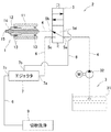
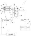
図1は、流路切換弁が切削液供給源と主軸装置とを連通させている構成を示している。図2は、流路切換弁が切削液供給源とエジェクタとを連通させている構成を示している。図3は、この発明に使用されるエジェクタの断面図を示している。図4は、エジェクタから流出した切削液が切削液供給源に戻される構成を示している。 FIG. 1 shows a configuration in which the flow path switching valve makes the cutting fluid supply source and the spindle device communicate with each other. FIG. 2 shows a configuration in which the flow path switching valve makes the cutting fluid supply source and the ejector communicate with each other. FIG. 3 shows a cross-sectional view of the ejector used in the present invention. FIG. 4 shows a configuration in which the cutting fluid flowing out from the ejector is returned to the cutting fluid supply source.
図1および図2に示すように、工作機械は、主軸装置(1)と、主軸装置(1)への切削液の供給および回収を行う切削液供給回収装置(2)とを備えている。 As shown in FIGS. 1 and 2, the machine tool includes a spindle device (1) and a cutting fluid supply / recovery device (2) that supplies and recovers the cutting fluid to the spindle device (1).
主軸装置(1)は、円筒形の中空部を有するハウジング(11)を有している。ハウジング(11)の中空部には、先端部にテーパ状の工具ホルダ装着孔を有する主軸(12)がベアリング(13)を介して回転自在に支持されており、工具ホルダ装着孔に切削工具が取り付けられた工具ホルダ(14)が装着されている。 The spindle device (1) has a housing (11) having a cylindrical hollow portion. In the hollow portion of the housing (11), a spindle (12) having a tapered tool holder mounting hole at the tip is rotatably supported via a bearing (13), and a cutting tool is placed in the tool holder mounting hole. The attached tool holder (14) is mounted.
切削液を工具の先端からワーク加工領域に向けて吐出させるために、主軸(12)および工具ホルダ(14)の内部には、切削液流通孔(15)が設けられている。 A cutting fluid circulation hole (15) is provided in the main shaft (12) and the tool holder (14) in order to discharge the cutting fluid from the tip of the tool toward the workpiece machining area.
切削液供給回収装置(2)は、切削液を貯留する切削液供給源(3)と、切削液供給源(3)と主軸装置(1)の後端との間に設けられた切削液主流路(4)と、切削液主流路(4)の途中に設けられて流路をワークの加工領域および加工領域以外の供給先のいずれかに切り替える流路切換弁(5)と、加工領域以外の供給先に切削液を供給する切削液副流路(6)と、切削液副流路(6)の途中に設けられて負圧により主軸装置(1)における切削液流通孔(15)内の切削液を吸引するエジェクタ(7)とを備えている。 The cutting fluid supply and recovery device (2) includes a cutting fluid supply source (3) for storing cutting fluid, and a cutting fluid main flow provided between the cutting fluid supply source (3) and the rear end of the spindle device (1). A channel switching valve (5) that is provided in the middle of the channel (4) and the cutting fluid main channel (4) and switches the channel to either the machining area of the workpiece or a supply destination other than the machining area, and other than the machining area The cutting fluid sub-channel (6) for supplying the cutting fluid to the supply destination, and the cutting fluid circulation passage (15) in the spindle device (1) provided in the middle of the cutting fluid sub-channel (6) by the negative pressure And an ejector (7) for sucking the cutting fluid.
切削液主流路(4)において、流路切換弁(5)と切削液供給源(3)との間に接続されている側を1次側の切削液主流路(4)といい、流路切換弁(5)と主軸(12)との間に接続されている側を2次側の切削液主流路(4)というものとする。 In the cutting fluid main channel (4), the side connected between the channel switching valve (5) and the cutting fluid supply source (3) is called the primary cutting fluid main channel (4). The side connected between the switching valve (5) and the main shaft (12) is referred to as a secondary cutting fluid main flow path (4).
切削液供給源(3)は、切削液タンク(31)と、ポンプ(32)とを備えている。ポンプ(32)の吸込口は、管路を介して切削液タンク(31)に接続されている。ポンプ(32)の流出口には、1次側の切削液主流路(4)の基端が接続されている。切削液タンク(31)からポンプ(32)により吸引された切削液は、ワーク加工領域に切削液を供給する場合、図1に示すように流路切換弁(5)を介して主軸(12)の切削液流通孔(15)に供給されており、ワーク加工領域以外の供給先(この実施形態では、ワーク加工室)に供給する場合、図2に示すように流路切換弁(5)を介して切削液副流路(6)の途中に設けられたエジェクタ(7)に供給されている。 The cutting fluid supply source (3) includes a cutting fluid tank (31) and a pump (32). The suction port of the pump (32) is connected to the cutting fluid tank (31) through a pipe line. The base end of the primary cutting fluid main channel (4) is connected to the outlet of the pump (32). When the cutting fluid sucked by the pump (32) from the cutting fluid tank (31) is supplied to the workpiece machining area, the spindle (12) is connected via the flow path switching valve (5) as shown in FIG. In the case of supplying to a supply destination (work processing chamber in this embodiment) other than the work processing region, the flow path switching valve (5) is provided as shown in FIG. And is supplied to an ejector (7) provided in the middle of the cutting fluid sub-channel (6).
エジェクタ(7)は、一般的に周知の流体排出装置であり、エジェクタ(7)内に形成された噴出ノズル(71)から第1の流体を高速に噴出し、噴流の巻き込み作用により負圧を発生させて、この負圧により第2の流体を吸引、排出する機能を有する装置である。 The ejector (7) is a generally well-known fluid discharge device. The ejector (7) ejects a first fluid from an ejection nozzle (71) formed in the ejector (7) at a high speed, and negative pressure is generated by the entrainment action of the jet. The device has a function of generating and sucking and discharging the second fluid by this negative pressure.
図3に示すように、エジェクタ(7)は、中空状に形成され、切削液供給源(3)から切削液が流路切換弁(5)を介して供給される供給ポート(7a)と、切削液流通孔(15)に残留する切削液を吸引する吸引ポート(7b)と、エジェクタ(7)内の切削液が流出する流出ポート(7c)とを有している。 As shown in FIG. 3, the ejector (7) is formed in a hollow shape, and a supply port (7a) to which cutting fluid is supplied from a cutting fluid supply source (3) via a flow path switching valve (5); A suction port (7b) that sucks the cutting fluid remaining in the cutting fluid circulation hole (15) and an outflow port (7c) through which the cutting fluid in the ejector (7) flows out are provided.
供給ポート(7a)には、流路切換弁(5)からのびた切削液副流路(6)が接続されている。 A cutting fluid sub-flow passage (6) extending from the flow passage switching valve (5) is connected to the supply port (7a).
供給ポート(7a)は、エジェクタ(7)内に形成された噴出ノズル(71)と連通している。噴出ノズル(71)は、供給ポート(7a)に所定の圧力で供給された切削液が、流出ポート(7c)に向けて高速の噴流状に噴出されるように形成されている。 The supply port (7a) communicates with an ejection nozzle (71) formed in the ejector (7). The ejection nozzle (71) is formed so that the cutting fluid supplied at a predetermined pressure to the supply port (7a) is ejected in a high-speed jet toward the outflow port (7c).
吸引ポート(7b)は、噴出ノズル(71)先端より供給ポート(7a)に近接した側面に形成されている。 The suction port (7b) is formed on the side surface close to the supply port (7a) from the tip of the ejection nozzle (71).
エジェクタ(7)と流路切換弁(5)との間には、エジェクタ(7)の吸引により切削液流通孔(15)の切削液が流路切換弁(5)を介して流通する切削液吸引流路(8)が接続されており、吸引ポート(7b)に、切削液吸引流路(8)の先端が接続されている。 Between the ejector (7) and the flow path switching valve (5), the cutting fluid in which the cutting fluid in the cutting fluid circulation hole (15) flows through the flow path switching valve (5) by suction of the ejector (7). The suction channel (8) is connected, and the tip of the cutting fluid suction channel (8) is connected to the suction port (7b).
切削液副流路(6)の先端は、ワーク加工室に設置された切粉洗浄ノズル(9)に接続されており、流出ポート(7c)には、先端が切粉洗浄ノズル(9)に接続された切削液副流路(6)が接続されている。 The tip of the cutting fluid sub-channel (6) is connected to the chip cleaning nozzle (9) installed in the workpiece processing chamber, and the tip is connected to the chip cleaning nozzle (9) at the outflow port (7c). The connected cutting fluid subchannel (6) is connected.
流路切換弁(5)は、流路方向を切り換えるソレノイド方式の電磁弁であり、第1ないし第4のポート(5a)(5b)(5c)(5d)を有している。 The flow path switching valve (5) is a solenoid type solenoid valve that switches the flow path direction, and has first to fourth ports (5a), (5b), (5c), and (5d).
流路切換弁(5)は、図1に示すように、ワーク加工時に流路切換弁(5)が励磁された状態にあり、第1のポート(5a)と第2のポート(5b)とが連通しており、第3のポート(5c)と第4のポート(5d)との間が遮断されている第1の流路形態と、図2に示すように、ワークの非加工時に流路切換弁(5)が消磁されて、第1のポート(5a)と第3のポート(5c)が連通するとともに第2のポート(5b)と第4のポート(5d)とが連通している第2の流路形態との間での切り換えが行われるようになっている。 As shown in FIG. 1, the flow path switching valve (5) is in a state in which the flow path switching valve (5) is excited during workpiece machining, and the first port (5a) and the second port (5b) Are connected to each other, and the first flow path configuration in which the third port (5c) and the fourth port (5d) are blocked from each other, as shown in FIG. The path switching valve (5) is demagnetized so that the first port (5a) and the third port (5c) communicate with each other, and the second port (5b) and the fourth port (5d) communicate with each other. Switching to the second flow path configuration is performed.
流路切換弁(5)は、図示しない制御装置に接続されており、制御装置によって流路の切り換えが行われている。 The flow path switching valve (5) is connected to a control device (not shown), and the flow path is switched by the control device.
第1のポート(5a)には、流路切換弁(5)の1次側の切削液主流路(4)の先端が接続され、第2のポート(5b)には、流路切換弁(5)の2次側の切削液主流路(4)の基端が接続されている。 The first port (5a) is connected to the leading end of the cutting fluid main flow path (4) on the primary side of the flow path switching valve (5), and the second port (5b) is connected to the flow path switching valve (5a). The base end of the secondary cutting fluid main flow path (4) of 5) is connected.
第3のポート(5c)には、切削液副流路(6)の基端が接続され、第4のポート(5d)には、切削液吸引流路(8)の基端が接続されている。 The third port (5c) is connected to the base end of the cutting fluid sub-channel (6), and the fourth port (5d) is connected to the base end of the cutting fluid suction channel (8). Yes.
流路切換弁(5)の1次側の切削液主流路(4)の基端は、ポンプ(32)の流出口に接続されている。 The base end of the cutting fluid main flow path (4) on the primary side of the flow path switching valve (5) is connected to the outlet of the pump (32).
流路切換弁(5)の2次側の切削液主流路(4)の先端は、ロータリージョイント(図示略)等を介して主軸(12)の切削液流通孔(15)の後端に接続されている。切削液供給源(3)から供給された切削液は、切削液流通孔(15)の後端から先端に流通して、工具先端からワーク加工領域に噴出される。 The tip of the cutting fluid main channel (4) on the secondary side of the channel switching valve (5) is connected to the rear end of the cutting fluid circulation hole (15) of the main shaft (12) via a rotary joint (not shown). Has been. The cutting fluid supplied from the cutting fluid supply source (3) flows from the rear end to the tip of the cutting fluid circulation hole (15), and is ejected from the tip of the tool to the workpiece machining area.
第3のポート(5c)に接続された切削液副流路(6)は、エジェクタ(7)の供給ポート(7a)に接続されている。 The cutting fluid sub-channel (6) connected to the third port (5c) is connected to the supply port (7a) of the ejector (7).
次に、この発明による第1実施形態の工作機械の切削液供給回収装置(2)の作用を説明する。 Next, the operation of the cutting fluid supply / recovery device (2) for the machine tool according to the first embodiment of the present invention will be described.
まず、図1に示すように、工作機械がワークの切削加工を行う際、流路切換弁(5)は、励磁されて第1のポート(5a)と第2のポート(5b)とが連通する第1の流路形態となる。これにより切削液タンク(31)内の切削液は、ポンプ(32)により、切削液主流路(4)および流路切換弁(5)の第1、第2のポート(5a)(5b)を介して主軸(12)の切削液流通孔(15)に供給される。切削液流通孔(15)に供給された高圧の切削液は、主軸(12)および工具ホルダ(14)を貫通してワークの加工領域に向けて噴出される。 First, as shown in FIG. 1, when the machine tool cuts a workpiece, the flow path switching valve (5) is excited and the first port (5a) communicates with the second port (5b). It becomes the 1st flow path form to do. As a result, the cutting fluid in the cutting fluid tank (31) is supplied to the cutting fluid main channel (4) and the first and second ports (5a) and (5b) of the channel switching valve (5) by the pump (32). To the cutting fluid circulation hole (15) of the main shaft (12). The high-pressure cutting fluid supplied to the cutting fluid flow hole (15) passes through the spindle (12) and the tool holder (14) and is ejected toward the workpiece machining area.
所定の加工プロセスが終了すると、主軸(12)の回転が停止され、工作機械が工具の交換動作を開始する。 When the predetermined machining process is completed, the rotation of the spindle (12) is stopped and the machine tool starts the tool changing operation.
このとき、図2に示すように、流路切換弁(5)が消磁されて、第1のポート(5a)と第3のポート(5c)が連通するとともに第2のポート(5b)と第4のポート(5d)とが連通する第2の流路形態となる。これによりポンプ(32)の流出口が、流路切換弁(5)の1次側の切削液主流路(4)、流路切換弁(5)の第1、第3のポート(5a)(5c)および切削液副流路(6)を介してエジェクタ(7)の供給ポート(7a)に連通するとともに、主軸(12)の切削液流通孔(15)が、流路切換弁(5)の2次側の切削液主流路(4)、流路切換弁(5)の第2、第4のポート(5b)(5d)および切削液吸引流路(8)を介してエジェクタ(7)の吸引ポート(7b)に連通する。 At this time, as shown in FIG. 2, the flow path switching valve (5) is demagnetized so that the first port (5a) and the third port (5c) communicate with each other and the second port (5b) and the second port (5b) communicate with each other. It becomes the 2nd channel form which 4 ports (5d) communicate. As a result, the outlet of the pump (32) is connected to the cutting fluid main flow path (4) on the primary side of the flow path switching valve (5) and the first and third ports (5a) of the flow path switching valve (5). 5c) and the cutting fluid sub-flow channel (6) communicated with the supply port (7a) of the ejector (7), and the cutting fluid circulation hole (15) of the main shaft (12) is connected to the flow switching valve (5). Ejector (7) via the cutting fluid main channel (4) on the secondary side, the second and fourth ports (5b) (5d) of the channel switching valve (5) and the cutting fluid suction channel (8) To the suction port (7b).
ポンプ(32)から流路切換弁(5)の第1、第3のポート(5a)(5c)を介してエジェクタ(7)の供給ポート(7a)に切削液が供給されると、エジェクタ(7)の噴出ノズル(71)から噴出する高速の切削液により負圧が発生し、吸引ポート(7b)の圧力が大気圧よりも低下する。これとほぼ同時に、主軸(12)および工具ホルダ(14)の切削液流通孔(15)に残留していた切削液が流路切換弁(5)の第2、第4のポート(5b)(5d)を介して吸引ポート(7b)からエジェクタ(7)に吸引され、供給ポート(7a)からエジェクタ(7)に供給される切削液とともにエジェクタ(7)の流出ポート(7c)から切削液が流出する。 When cutting fluid is supplied from the pump (32) to the supply port (7a) of the ejector (7) via the first and third ports (5a) and (5c) of the flow path switching valve (5), the ejector ( A negative pressure is generated by the high-speed cutting fluid ejected from the ejection nozzle (71) of 7), and the pressure of the suction port (7b) decreases below the atmospheric pressure. At substantially the same time, the cutting fluid remaining in the cutting fluid circulation hole (15) of the spindle (12) and the tool holder (14) is transferred to the second and fourth ports (5b) ( The cutting fluid is sucked into the ejector (7) from the suction port (7b) through the suction port (5d) and supplied from the supply port (7a) to the ejector (7), along with the cutting fluid from the outlet port (7c) of the ejector (7). leak.
所定の時間、切削液の吸引を継続して主軸(12)および工具ホルダ(14)の切削液流通孔(15)に残留する切削液が除去された後、工作機械の制御装置によりポンプ(32)の動作を停止する。ポンプ(32)の動作を停止するとエジェクタ(7)の供給ポート(7a)に切削液が供給されなくなるので、エジェクタ(7)による切削液の吸引動作も停止する。 The suction of the cutting fluid is continued for a predetermined time, and the cutting fluid remaining in the cutting fluid circulation hole (15) of the spindle (12) and the tool holder (14) is removed, and then the pump (32 ) Is stopped. When the operation of the pump (32) is stopped, the cutting fluid is not supplied to the supply port (7a) of the ejector (7), so the suction operation of the cutting fluid by the ejector (7) is also stopped.
切削液流通孔(15)から切削液が漏れるのは、切削液流通孔(15)に切削液が残留しているときに工具ホルダ(14)を主軸(12)から取り外す場合や、工具を交換する場合であるので、切削液が切削液流通孔(15)から除去された後は、工具ホルダ(14)の取り外しや工具の交換によって、切削液が漏れ出すことはない。 Cutting fluid leaks from the cutting fluid circulation hole (15) when the cutting fluid remains in the cutting fluid circulation hole (15) when the tool holder (14) is removed from the spindle (12) or the tool is replaced. Therefore, after the cutting fluid is removed from the cutting fluid circulation hole (15), the cutting fluid does not leak out by removing the tool holder (14) or replacing the tool.
また、上記特許文献1記載の工作機械の切削液供給回収装置は、主軸(12)と流路切換弁(5)との間の流路に、エジェクタ(7)へ向かう流路が分岐されて設けられている。そのため、圧力損失によりエジェクタ(7)の吸引力が低下する。
Further, in the cutting fluid supply and recovery apparatus for machine tools described in
しかし、本願発明の工作機械の切削液供給回収装置(2)では、主軸(12)から流路切換弁(5)までの間に分岐した流路がなく、主軸(12)からエジェクタ(7)まで直通となっているので、圧力損失がなく、吸引力が低下するおそれはない。 However, in the cutting fluid supply and recovery device (2) of the machine tool of the present invention, there is no flow path branched from the main shaft (12) to the flow path switching valve (5), and the main shaft (12) to the ejector (7). Since there is no direct pressure, there is no pressure loss and there is no possibility that the suction force will decrease.
また、上記特許文献1記載の工作機械の切削液供給回収装置は、複数の弁を使用しているが、本願発明の工作機械の切削液供給回収装置(2)では、弁を1つに集約しているので、部品点数を削減することができる。
The cutting fluid supply / recovery device for machine tools described in
図1および図2に示すように、エジェクタ(7)の流出ポート(7c)からのびた切削液副流路(6)の先端が、ワーク加工室に設置された切粉洗浄ノズル(9)に接続されていると、主軸(12)および工具ホルダ(14)の切削液流通孔(15)から吸引した切削液やポンプ(32)からエジェクタ(7)に供給された切削液を切粉の洗浄に利用することができる。 As shown in FIGS. 1 and 2, the tip of the cutting fluid sub-channel (6) extending from the outflow port (7c) of the ejector (7) is connected to the chip cleaning nozzle (9) installed in the workpiece processing chamber. The cutting fluid sucked from the cutting fluid flow hole (15) of the spindle (12) and tool holder (14) and the cutting fluid supplied to the ejector (7) from the pump (32) Can be used.
一方、図4に示すように、この発明の第2実施形態として、エジェクタ(7)の流出ポート(7c)からのびた切削液副流路(6)の先端が、切削液タンク(31)に形成された切削液戻し口(31a)にのびて構成されている。切削液副流路(6)の先端が、切削液タンク(31)の切削液戻し口(31a)にのびていること以外は、図1および図2に示した第1実施形態の構成と同様であるので、図1および図2と同じ構成には同じ符号を付して、その説明を省略する。 On the other hand, as shown in FIG. 4, as a second embodiment of the present invention, the tip of the cutting fluid sub-channel (6) extending from the outflow port (7c) of the ejector (7) is formed in the cutting fluid tank (31). The cutting fluid return port (31a) extends. Except that the tip of the cutting fluid sub-channel (6) extends to the cutting fluid return port (31a) of the cutting fluid tank (31), it is the same as the configuration of the first embodiment shown in FIGS. Therefore, the same components as those in FIGS. 1 and 2 are denoted by the same reference numerals, and the description thereof is omitted.
流出ポート(7c)からのびた切削液副流路(6)の先端が、切削液タンク(31)の切削液戻し口(31a)にのびていると、エジェクタ(7)を介して主軸(12)および工具ホルダ(14)から吸引した切削液やポンプ(32)からエジェクタ(7)に供給された切削液を切削液タンク(31)内に回収して再利用することができる。 When the tip of the cutting fluid sub-channel (6) extending from the outflow port (7c) extends to the cutting fluid return port (31a) of the cutting fluid tank (31), the spindle (12) and The cutting fluid sucked from the tool holder (14) and the cutting fluid supplied from the pump (32) to the ejector (7) can be collected in the cutting fluid tank (31) and reused.
(2)・・・切削液供給回収装置
(3)・・・切削液供給源
(4)・・・切削液主流路
(5)・・・流路切換弁
(5a)・・・第1のポート
(5b)・・・第2のポート
(5c)・・・第3のポート
(5d)・・・第4のポート
(6)・・・切削液副流路
(7)・・・エジェクタ
(7b)・・・吸引ポート
(8)・・・切削液吸引流路
(12)・・・主軸
(14)・・・工具ホルダ
(15)・・・切削液流通孔
(2) ... Cutting fluid supply and recovery device (3) ... Cutting fluid supply source (4) ... Cutting fluid main flow path (5) ... Flow path switching valve (5a) ... First Port (5b) ... Second port (5c) ... Third port (5d) ... Fourth port (6) ... Cutting fluid subflow path (7) ... Ejector ( 7b) ... suction port (8) ... cutting fluid suction flow path (12) ... main shaft (14) ... tool holder (15) ... cutting fluid flow hole
Claims (3)
切削液主流路の途中に流路切換弁が設けられており、
流路切換弁は、第1ないし第4のポートを有するものであって、第1のポートに、流路切換弁の1次側の切削液主流路の先端が接続され、第2のポートに、流路切換弁の2次側の切削液主流路の基端が接続され、第3のポートに、切削液供給源からの切削液をワーク加工領域以外の供給先に供給する切削液副流路の基端が接続され、第4のポートに、切削液副流路の途中に設けられたエジェクタの吸引ポートに先端が接続されている切削液吸引流路の基端が接続されており、
この流路切換弁により、ワーク加工時に第1のポートと第2のポートとを連通させて切削液供給源からの切削液をワーク加工領域に供給する第1の流路形態と、ワーク非加工時に第1のポートと第3のポートを連通させるとともに第2のポートと第4のポートとを連通させて主軸および工具ホルダの内部の切削液流通孔に残留した切削液をエジェクタにより吸引して回収する第2の流路形態との間での切換が行われるようになっている、工作機械の切削液供給回収装置。
The cutting fluid supplied through the cutting fluid main flow path from the cutting fluid supply source flows through the cutting fluid circulation holes formed in the spindle and tool holder, and is discharged from the tip of the tool toward the workpiece machining area. Has been made,
A flow path switching valve is provided in the middle of the cutting fluid main flow path,
The flow path switching valve has first to fourth ports, the tip of the cutting fluid main flow path on the primary side of the flow path switching valve is connected to the first port, and the second port is connected to the first port. The secondary end of the cutting fluid main flow path on the secondary side of the flow path switching valve is connected, and the cutting fluid substream that supplies the cutting fluid from the cutting fluid supply source to a supply destination other than the workpiece machining area is connected to the third port. The base end of the path is connected, and the fourth port is connected to the base end of the cutting fluid suction flow path whose tip is connected to the suction port of the ejector provided in the middle of the cutting fluid sub-flow path,
By this flow path switching valve, a first flow path configuration in which the first port and the second port are communicated with each other at the time of workpiece machining to supply the cutting fluid from the cutting fluid supply source to the workpiece machining region, and workpiece non-machining Sometimes the first port and the third port are communicated with each other, and the second port and the fourth port are communicated to suck the cutting fluid remaining in the cutting fluid circulation holes inside the spindle and the tool holder with the ejector. A cutting fluid supply / recovery device for a machine tool, which is configured to be switched between a second flow path configuration to be recovered.
The cutting fluid supply / recovery device for a machine tool according to claim 1, wherein a tip of the cutting fluid sub-flow path is connected to a chip cleaning nozzle installed in the workpiece processing chamber.
The cutting fluid supply / recovery device for a machine tool according to claim 1, wherein a leading end of the cutting fluid sub-flow path is connected to a cutting fluid return port provided in a cutting fluid supply source.
Priority Applications (1)
| Application Number | Priority Date | Filing Date | Title |
|---|---|---|---|
| JP2017095518A JP2018192536A (en) | 2017-05-12 | 2017-05-12 | Cutting-liquid supply recovery system of machine tool |
Applications Claiming Priority (1)
| Application Number | Priority Date | Filing Date | Title |
|---|---|---|---|
| JP2017095518A JP2018192536A (en) | 2017-05-12 | 2017-05-12 | Cutting-liquid supply recovery system of machine tool |
Publications (1)
| Publication Number | Publication Date |
|---|---|
| JP2018192536A true JP2018192536A (en) | 2018-12-06 |
Family
ID=64571037
Family Applications (1)
| Application Number | Title | Priority Date | Filing Date |
|---|---|---|---|
| JP2017095518A Pending JP2018192536A (en) | 2017-05-12 | 2017-05-12 | Cutting-liquid supply recovery system of machine tool |
Country Status (1)
| Country | Link |
|---|---|
| JP (1) | JP2018192536A (en) |
Cited By (2)
| Publication number | Priority date | Publication date | Assignee | Title |
|---|---|---|---|---|
| CN113508007A (en) * | 2019-03-05 | 2021-10-15 | 西铁城时计株式会社 | Cutting oil tank, machine tool and machine tool system |
| JP7489299B2 (en) | 2020-11-26 | 2024-05-23 | オークマ株式会社 | Cutting fluid supply and recovery device for machine tools |
-
2017
- 2017-05-12 JP JP2017095518A patent/JP2018192536A/en active Pending
Cited By (3)
| Publication number | Priority date | Publication date | Assignee | Title |
|---|---|---|---|---|
| CN113508007A (en) * | 2019-03-05 | 2021-10-15 | 西铁城时计株式会社 | Cutting oil tank, machine tool and machine tool system |
| CN113508007B (en) * | 2019-03-05 | 2023-08-22 | 西铁城时计株式会社 | Cutting oil tank, machine tool and machine tool system |
| JP7489299B2 (en) | 2020-11-26 | 2024-05-23 | オークマ株式会社 | Cutting fluid supply and recovery device for machine tools |
Similar Documents
| Publication | Publication Date | Title |
|---|---|---|
| US6179692B1 (en) | Work machining method | |
| JPH09262710A (en) | Apparatus for preventing cutting chipps from adhering to drill shank | |
| KR20000022012A (en) | Workpiece processing method and misty material supplier thereof | |
| JP2965468B2 (en) | Processing fluid supply device | |
| US20030220059A1 (en) | Vacuum chuck apparatus | |
| JP3788277B2 (en) | Deep hole cutting equipment | |
| CN201559087U (en) | Machine tool | |
| JPS5953141A (en) | Cutting tool apparatus with chips suction apparatus | |
| KR100624651B1 (en) | Die and die device | |
| JPH11138382A (en) | Main spindle device | |
| CN108687566B (en) | Cleaning device and cleaning method | |
| JP7489299B2 (en) | Cutting fluid supply and recovery device for machine tools | |
| JP5321412B2 (en) | Tool cleaning equipment for machine tools | |
| KR102134486B1 (en) | Supply apparatus through spindle coolant and air of machine tool | |
| JP2019506306A (en) | Boring bar actuated by centrifugal force | |
| JP7304217B2 (en) | Cutting fluid supply and recovery device in the spindle of a machine tool | |
| JP3620954B2 (en) | Cutting fluid supply device | |
| EP1693146A1 (en) | Deep hole boring method and device | |
| JP2006187834A (en) | Cutting equipment | |
| JP3456628B2 (en) | Tool holder | |
| JP2012218127A (en) | Mechanism for sucking chips in machine tool | |
| US6642469B2 (en) | Electrode clamping system for sink-type electrical discharge machines | |
| JP2003062736A (en) | Main spindle apparatus for machine tool | |
| JP2002178207A (en) | Fine hole drilling method, tool holder and machining center used therefor | |
| JP2005059165A (en) | Cleaning device for tool holder fitting portion of spindle device in machine tool |