JP2018197048A - Collision avoidance control device - Google Patents
Collision avoidance control device Download PDFInfo
- Publication number
- JP2018197048A JP2018197048A JP2017101942A JP2017101942A JP2018197048A JP 2018197048 A JP2018197048 A JP 2018197048A JP 2017101942 A JP2017101942 A JP 2017101942A JP 2017101942 A JP2017101942 A JP 2017101942A JP 2018197048 A JP2018197048 A JP 2018197048A
- Authority
- JP
- Japan
- Prior art keywords
- avoidance
- obstacle
- area
- cost
- vehicle
- Prior art date
- Legal status (The legal status is an assumption and is not a legal conclusion. Google has not performed a legal analysis and makes no representation as to the accuracy of the status listed.)
- Granted
Links
Images





Landscapes
- Steering Control In Accordance With Driving Conditions (AREA)
- Control Of Driving Devices And Active Controlling Of Vehicle (AREA)
- Regulating Braking Force (AREA)
- Traffic Control Systems (AREA)
Abstract
【課題】 回避経路が安全な走行経路であるか否かを精度よく判定する。【解決手段】 衝突回避制御装置は、前方障害物との衝突を回避するための回避経路を設定する回避経路設定手段と、回避経路の信頼度を算出する信頼度算出手段と、回避経路に沿った自動操舵を実行するか否かを判定する自動操舵制御手段と、車両前方の領域を複数個の領域に分割してなる単位領域62が障害物領域であるか不明領域であるかを特定する単位領域特定手段を備える。自車両から同一の距離においては、障害物領域のほうが不明領域よりもコストが高く設定されている。信頼度算出手段は、回避経路を含む回避領域内に存在する障害物領域の個数及びコスト並びに不明領域の個数及びコストに基づいて回避領域コストを算出し、回避領域コストに基づいて回避経路の信頼度を算出する。【選択図】 図5APROBLEM TO BE SOLVED: To accurately determine whether or not an avoidance route is a safe traveling route. A collision avoidance control device includes an avoidance route setting means for setting an avoidance route for avoiding a collision with a front obstacle, a reliability calculation means for calculating the reliability of the avoidance route, and an avoidance route. The automatic steering control means for determining whether or not to execute the automatic steering and the unit region 62 formed by dividing the region in front of the vehicle into a plurality of regions are specified as an obstacle region or an unknown region. A unit area specifying means is provided. At the same distance from the own vehicle, the obstacle area is set to be more costly than the unknown area. The reliability calculation means calculates the avoidance area cost based on the number and cost of obstacle areas existing in the avoidance area including the avoidance route and the number and cost of unknown areas, and trusts the avoidance route based on the avoidance area cost. Calculate the degree. [Selection diagram] FIG. 5A
Description
本発明は、車両の前方に存在する障害物に車両が衝突することを回避又は軽減する制御を行う衝突回避制御装置に関する。 The present invention relates to a collision avoidance control apparatus that performs control for avoiding or reducing the collision of a vehicle with an obstacle existing in front of the vehicle.
従来から、車両の前方に存在する障害物に車両が衝突することを回避又は軽減するための制御(衝突回避制御)を行う衝突回避制御装置が知られている。衝突回避制御装置は、車両の前方に当該車両が衝突する可能性がある障害物が存在する場合、衝突回避制御として、自動制動制御(車両に制動力を自動的に付与する制御)又は自動制動制御を伴う自動操舵制御(車両の操舵輪の転舵角を自動的に変更する制御)を実行する。自動操舵制御を実行する際は、衝突回避制御装置は、障害物との衝突を回避するための経路である回避経路を予め設定しておき、当該回避経路に沿って車両が走行するように車両を制御する。以下、衝突回避制御装置が搭載された車両を「自車両」とも称する。 2. Description of the Related Art Conventionally, a collision avoidance control device that performs control (collision avoidance control) for avoiding or reducing the collision of a vehicle with an obstacle existing in front of the vehicle is known. The collision avoidance control device uses automatic braking control (control for automatically applying braking force to the vehicle) or automatic braking as collision avoidance control when there is an obstacle that may cause the vehicle to collide in front of the vehicle. Automatic steering control with control (control for automatically changing the turning angle of the steering wheel of the vehicle) is executed. When executing the automatic steering control, the collision avoidance control device sets in advance an avoidance route that is a route for avoiding a collision with an obstacle, and the vehicle travels along the avoidance route. To control. Hereinafter, the vehicle equipped with the collision avoidance control device is also referred to as “own vehicle”.
このような衝突回避制御装置において、回避経路上に別の障害物が存在する場合に上記の自動操舵制御を行うと、当該制御の実行前に自車両の前方に存在していた障害物との衝突回避は達成できても、回避経路上の別の障害物との衝突を回避するための制御を新たに行わなければならず、適切に衝突回避できない可能性、又は、不自然な(連続的な)衝突回避になってしまう可能性がある。この場合、自車両のドライバに対して違和感や不信感を与える可能性があり、好ましくない。 In such a collision avoidance control device, when the above-described automatic steering control is performed when another obstacle exists on the avoidance route, the obstacle avoidance that exists in front of the host vehicle before the execution of the control. Even if collision avoidance can be achieved, new control must be performed to avoid a collision with another obstacle on the avoidance path, and it may not be possible to avoid collision properly or unnatural (continuous) There is a possibility of collision avoidance. In this case, the driver of the own vehicle may be uncomfortable or distrustful, which is not preferable.
そこで、特許文献1に開示される衝突回避制御装置(以下、「従来装置」と称する。)は、回避経路上に別の障害物が存在する場合、自動操舵制御は実行せずに自動制動制御のみで衝突回避を実行するように構成されている。従来装置によれば、自動操舵制御を実行する前に回避経路が安全な走行経路であるか否かを判定するため、自動操舵制御により不適切又は不自然な衝突回避が実行される可能性を低減できると記載されている。 Therefore, the collision avoidance control device (hereinafter referred to as “conventional device”) disclosed in Patent Document 1 does not execute automatic steering control when another obstacle exists on the avoidance route, and performs automatic braking control. It is configured to perform collision avoidance only. According to the conventional device, in order to determine whether or not the avoidance route is a safe travel route before executing the automatic steering control, there is a possibility that inappropriate or unnatural collision avoidance is executed by the automatic steering control. It is described that it can be reduced.
従来装置は、回避経路が安全な走行経路であるか否かを、回避経路上に障害物が存在するか否かのみに基づいて判定している。しかしながら、この構成では、回避経路が安全な走行経路であるか否かを精度よく判定できない可能性がある。即ち、例えば、回避経路上に障害物が存在していなくても、回避経路上の路面に何らかの要因により自車両が安全に走行できない程度の窪みや傾斜面が形成されている場合、当該回避経路は安全な走行経路とは言えない。しかしながら、従来装置の構成によれば、このような回避経路も安全な走行経路であると判定してしまう可能性があるため、判定精度が低下する可能性がある。 The conventional device determines whether the avoidance route is a safe travel route based only on whether there is an obstacle on the avoidance route. However, with this configuration, it may not be possible to accurately determine whether the avoidance route is a safe travel route. That is, for example, if there is a depression or an inclined surface on the road surface on the avoidance route that does not allow the vehicle to travel safely even if there are no obstacles on the avoidance route, the avoidance route Is not a safe route. However, according to the configuration of the conventional device, such an avoidance route may be determined to be a safe travel route, and thus the determination accuracy may be reduced.
本発明は、上述した問題に対処するためになされたものである。即ち、本発明の目的の一つは、回避経路が安全な走行経路であるか否かを精度よく判定できる衝突回避制御装置を提供することにある。 The present invention has been made to address the above-described problems. That is, one of the objects of the present invention is to provide a collision avoidance control device that can accurately determine whether or not an avoidance route is a safe travel route.
本発明による衝突回避制御装置(以下、「本発明装置」とも称する。)は、
車両に搭載されており、
二つのカメラセンサにより撮像された車両前方の撮像画像から取得される視差情報と、輝度値を含む画素情報と、に基づいて障害物、路面及び白線を検出し、当該障害物、路面及び白線の位置を周辺情報として取得する周辺情報取得手段と、
前記検出された障害物のうち、前記車両の進行方向前方に、前記車両が衝突するまでに要すると予測される衝突予測時間が所定の第1時間閾値以下の障害物である前方障害物が存在する場合に、当該前方障害物との衝突を回避するための回避経路を設定する回避経路設定手段と、
前記回避経路が前記車両の走行経路として安全であるか否かを示す尺度である信頼度を算出する信頼度算出手段と、
前記前方障害物までの前記衝突予測時間が前記第1時間閾値以下である所定の第2時間閾値以下になった場合に車両に制動力を自動的に付与する自動制動制御を実行する自動制動制御手段と、
前記前方障害物までの前記衝突予測時間が前記第2時間閾値以下である所定の第3時間閾値になった時点において、前記車両が前記自動制動制御中であり、且つ、前記自動制動制御による減速度に基づく制動距離が前記前方障害物までの距離よりも長く、且つ、前記回避経路の前記信頼度が所定の信頼度閾値以上であるという特定条件が成立するか否かを判定し、前記特定条件が成立すると判定した場合、前記回避経路に沿って前記車両が走行するように前記車両の操舵輪の転舵角を自動的に変更する自動操舵制御を実行し、前記特定条件が成立しないと判定した場合、前記自動操舵制御を実行しない自動操舵制御手段と、
を備える。
A collision avoidance control apparatus according to the present invention (hereinafter also referred to as “the present invention apparatus”)
Mounted on the vehicle,
An obstacle, a road surface, and a white line are detected based on parallax information acquired from the captured image in front of the vehicle captured by the two camera sensors and pixel information including a luminance value, and the obstacle, the road surface, and the white line are detected. Peripheral information acquisition means for acquiring the position as peripheral information;
Among the detected obstacles, there is a front obstacle that is an obstacle whose predicted collision time is estimated to be required before the vehicle collides in the forward direction of the vehicle, which is equal to or less than a predetermined first time threshold. An avoidance route setting means for setting an avoidance route for avoiding a collision with the front obstacle,
Reliability calculation means for calculating a reliability that is a measure indicating whether the avoidance route is safe as a travel route of the vehicle;
Automatic braking control for executing automatic braking control for automatically applying a braking force to the vehicle when the predicted collision time to the forward obstacle is not more than a predetermined second time threshold which is not more than the first time threshold. Means,
When the predicted collision time to the forward obstacle reaches a predetermined third time threshold value that is equal to or less than the second time threshold value, the vehicle is in the automatic braking control and is reduced by the automatic braking control. Determining whether or not a specific condition is satisfied that a braking distance based on speed is longer than a distance to the forward obstacle and the reliability of the avoidance path is equal to or greater than a predetermined reliability threshold; If it is determined that the condition is satisfied, automatic steering control is executed to automatically change the turning angle of the steering wheel of the vehicle so that the vehicle travels along the avoidance route, and the specific condition is not satisfied. If it is determined, automatic steering control means that does not execute the automatic steering control,
Is provided.
本発明装置では、回避経路設定手段が、衝突予測時間が第1時間閾値以下である前方障害物が存在する場合、当該前方障害物との衝突を回避するための回避経路を設定し、信頼度算出手段が、当該回避経路の信頼度を算出する。そして、自動操舵制御手段が、前方障害物までの衝突予測時間が第3時間閾値になった時点において、特定条件が成立するか否かを判定する。この特定条件には、信頼度算出手段によって算出された信頼度が信頼度閾値以上であるという条件が含まれている。自動操舵制御手段は、特定条件が成立すると判定した場合、上記回避経路に沿って自動操舵制御を実行する。 In the device according to the present invention, when there is a front obstacle whose predicted collision time is equal to or less than the first time threshold, the avoidance path setting unit sets an avoidance path for avoiding a collision with the front obstacle, and the reliability The calculating means calculates the reliability of the avoidance route. Then, the automatic steering control means determines whether or not the specific condition is satisfied when the predicted collision time to the front obstacle becomes the third time threshold. This specific condition includes a condition that the reliability calculated by the reliability calculation means is equal to or higher than a reliability threshold. When it is determined that the specific condition is satisfied, the automatic steering control means performs automatic steering control along the avoidance path.
このような衝突回避制御装置では、回避経路上に別の障害物が存在するか否かを演算周期毎に判定し、障害物が存在しない場合は当該回避経路は安全であると判定し、障害物が存在する場合は当該回避経路は安全であると判定することが行われている。しかしながら、回避経路上に障害物が存在していなくても回避経路が安全とは言えない場合がある(具体的には、回避経路上の路面に窪みや傾斜面が形成されている場合。)。従来の衝突回避制御装置では、このような場合にも当該回避経路は安全であると判定する可能性があるため、好ましくない。回避経路が安全な走行経路であるか否かを従来よりも精度よく判定する技術が望まれている。 In such a collision avoidance control device, it is determined for each calculation cycle whether another obstacle exists on the avoidance route, and if there is no obstacle, the avoidance route is determined to be safe, When an object exists, it is determined that the avoidance route is safe. However, the avoidance path may not be safe even if there are no obstacles on the avoidance path (specifically, when a depression or an inclined surface is formed on the road surface on the avoidance path). . The conventional collision avoidance control device is not preferable because there is a possibility that the avoidance route is safe even in such a case. There is a demand for a technique for determining whether or not an avoidance route is a safe travel route with higher accuracy than in the past.
そこで、本発明装置は、
更に、前記車両前方の領域を複数の単位領域に分割したときの単位領域のそれぞれが、障害物が存在する障害物領域であるか、又は、前記車両が安全に走行できる領域であるか不明である不明領域であるか、を前記周辺情報に基づいて特定する単位領域特定手段と、
を備え、
前記単位領域は、領域の種類に応じて異なるコストを有しており、前記車両から前記障害物領域までの距離と前記車両から前記不明領域までの距離が略同一の場合、前記障害物領域のコストは前記不明領域のコストよりも高く設定されており、
前記信頼度算出手段は、
前記前方障害物までの前記衝突予測時間が前記第1時間閾値から前記第3時間閾値になるまで、演算周期毎に、前記車両が前記回避経路に沿って走行したときに前記車両が通過する領域を含む回避領域内に存在する前記障害物領域の個数及びコスト、並びに、前記不明領域の個数及びコストに基づいて、前記回避領域の危険度を示す尺度である回避領域コストを算出し、
前記回避領域コストは、前記回避領域内に存在する前記障害物領域の個数及び前記不明領域の個数が多いほど大きくなるように設定されており、
前記回避領域コストが所定のコスト閾値以上の場合、前記信頼度を、直前の演算周期の信頼度から所定の値だけ減算した値として算出し、前記回避領域コストが前記コスト閾値未満の場合、前記信頼度を、直前の演算周期の信頼度に所定の値だけ加算した値として算出する、
ように構成されている。
Therefore, the device of the present invention is
Furthermore, it is unknown whether each of the unit areas when the area in front of the vehicle is divided into a plurality of unit areas is an obstacle area where an obstacle exists, or whether the vehicle can travel safely. A unit region specifying means for specifying whether it is a certain unknown region based on the peripheral information;
With
The unit area has a different cost depending on the type of area, and when the distance from the vehicle to the obstacle area and the distance from the vehicle to the unknown area are substantially the same, The cost is set higher than the cost of the unknown area,
The reliability calculation means includes
A region through which the vehicle passes when the vehicle travels along the avoidance path for each calculation period until the predicted collision time to the front obstacle reaches the third time threshold from the first time threshold. Based on the number and cost of the obstacle area existing in the avoidance area including, and the number and cost of the unknown area, to calculate the avoidance area cost that is a measure indicating the risk of the avoidance area,
The avoidance area cost is set to increase as the number of obstacle areas and the number of unknown areas existing in the avoidance area increase.
When the avoidance area cost is equal to or higher than a predetermined cost threshold, the reliability is calculated as a value obtained by subtracting a predetermined value from the reliability of the immediately preceding calculation cycle, and when the avoidance area cost is less than the cost threshold, The reliability is calculated as a value obtained by adding a predetermined value to the reliability of the previous calculation cycle.
It is configured as follows.
本発明装置によれば、単位領域特定手段が、「車両前方の領域を複数の単位領域に分割したときの単位領域のそれぞれが、障害物が存在する障害物領域であるか」を特定するだけではなく、「車両が安全に走行できる領域であるか不明である不明領域であるか」をも特定する。ここで、不明領域とは、典型的には窪みや傾斜面が形成された領域を表す。信頼度算出手段は、回避領域(回避経路を含む領域)の危険度を示す尺度である回避領域コストを、回避領域内に存在する障害物領域の個数及びコストだけではなく、回避領域内に存在する不明領域の個数及びコストにも基づいて算出する。そして、信頼度算出手段は、回避領域コストがコスト閾値以上の場合、信頼度を、直前の演算周期の信頼度から所定値だけ減算し、回避領域コストがコスト閾値未満の場合、信頼度を、直前の演算周期の信頼度に所定値だけ加算する。 According to the device of the present invention, the unit area specifying means only specifies whether each of the unit areas when the area in front of the vehicle is divided into a plurality of unit areas is an obstacle area where an obstacle exists. Instead, it also specifies “whether it is an area where the vehicle can travel safely or is an unknown area”. Here, the unknown region typically represents a region where a depression or an inclined surface is formed. The reliability calculation means presents the avoidance area cost, which is a measure of the risk of the avoidance area (the area including the avoidance path), in the avoidance area as well as the number and cost of the obstacle areas existing in the avoidance area. The number of unknown areas to be calculated and the cost are also calculated. Then, the reliability calculation means subtracts the reliability by a predetermined value from the reliability of the immediately preceding calculation cycle when the avoidance area cost is equal to or higher than the cost threshold, and when the avoidance area cost is less than the cost threshold, A predetermined value is added to the reliability of the immediately preceding calculation cycle.
この構成によれば、回避経路の信頼度には、障害物領域の個数及びコストだけではなく、不明領域の個数及びコストも反映される。加えて、不明領域及び障害物領域が車両から略同一の距離に存在する場合、障害物領域のコストは、不明領域のコストよりも高く設定される。障害物領域は、不明領域よりも、車両の走行経路としての危険度が高い。このため、回避経路の信頼度に不明領域の個数及びコストも反映させ、さらに、障害物領域と不明領域のコストの大小関係を上記のように設定することにより、回避領域の危険度をより正確に反映した回避領域コストを算出することができる。即ち、回避経路の安全度をより正確に反映した信頼度を算出することができる。結果として、回避経路が安全な走行経路であるか否かを従来よりも精度よく判定することができる。 According to this configuration, the reliability of the avoidance path reflects not only the number and cost of obstacle regions but also the number and cost of unknown regions. In addition, when the unknown area and the obstacle area exist at substantially the same distance from the vehicle, the cost of the obstacle area is set higher than the cost of the unknown area. The obstacle area has a higher degree of risk as a travel route of the vehicle than the unknown area. For this reason, the number of unknown areas and their costs are reflected in the reliability of the avoidance path, and moreover, the risk level of the avoidance area is more accurately determined by setting the size relationship between the obstacle area and the unknown area as described above. The avoidance area cost reflected in can be calculated. That is, the reliability that more accurately reflects the safety level of the avoidance path can be calculated. As a result, whether or not the avoidance route is a safe travel route can be determined with higher accuracy than in the past.
尚、上記説明においては、発明の理解を助けるために、実施形態に対応する発明の構成に対して、実施形態で用いた符号を括弧書きで添えているが、発明の各構成要件は前記符号によって規定される実施形態に限定されるものではない。 In the above description, in order to help the understanding of the invention, the reference numerals used in the embodiments are attached to the configuration of the invention corresponding to the embodiment in parentheses, but each constituent element of the invention is the reference numeral. It is not limited to the embodiment defined by.
(第1実施形態)
図1は、本発明の第1実施形態に係る衝突回避制御装置(以下、「第1装置」とも称する。)の概略システム構成図である。第1装置が搭載された車両を他車両と区別する必要がある場合、「自車両」と称する。第1装置は、自車両に衝突する可能性が高い障害物との衝突を回避するための衝突回避制御を実施して、ドライバの運転を支援する装置である。
(First embodiment)
FIG. 1 is a schematic system configuration diagram of a collision avoidance control device (hereinafter also referred to as “first device”) according to a first embodiment of the present invention. When it is necessary to distinguish a vehicle equipped with the first device from other vehicles, it is referred to as “own vehicle”. The first device is a device that supports the driving of the driver by performing collision avoidance control for avoiding a collision with an obstacle that is highly likely to collide with the host vehicle.
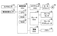
第1装置は衝突回避ECU10を備える。なお、ECUは、「Electirc Control Unit」の略であり、マイクロコンピュータを主要部として備える。マイクロコンピュータは、CPU31とROM32及びRAM33等の記憶装置とを含む。CPU31はROM32に格納されたインストラクション(プログラム、ルーチン)を実行することによって、各種機能を実現する。
The first device includes a
第1装置は、更に、カメラセンサ11、車両状態センサ12、ブレーキECU20、ブレーキセンサ21、ブレーキアクチュエータ22、ステアリングECU40、モータドライバ41、転舵用モータ42、警報ECU50及びブザー51を備える。衝突回避ECU10は、カメラセンサ11及び車両状態センサ12と接続されており、ブレーキECU20、ステアリングECU40及び警報ECU50と、通信・センサ系CAN(Controller Area Network)を介してデータ交換可能(通信可能)に接続されている。
The first device further includes a
カメラセンサ11は、自車両前方を撮像する車載ステレオカメラ装置(図示省略)を備える。車載ステレオカメラ装置は、自車両のルーフ前端部の車幅方向中央付近に設けられ、車両前後軸より左側に配置される左カメラと、車両前後軸より右側に配置される右カメラと、を有する。左カメラは所定時間が経過する毎に自車両前方の領域を撮像し、撮像した左画像を表す左画像信号を衝突回避ECU10に出力する。同様に、右カメラは所定時間が経過する毎に自車両前方の領域を撮像し、撮像した右画像を表す右画像信号を衝突回避ECU10に出力する。
The
車両状態センサ12は、自車両の走行状態に関する車両状態情報を取得するセンサである。車両状態センサ12は、自車両の速度(即ち、車速)を検出する車速センサ、自車両の水平方向の前後方向及び左右(横)方向の加速度を検出する加速度センサ、自車両のヨーレートYを検出するヨーレートセンサ、及び、操舵輪の転舵角を検出する転舵角センサ等を含む。ヨーレートYの値は、自車両が右方向に旋回する場合は正であり、左方向に旋回する場合は負である。車両状態センサ12は、所定時間が経過する毎に車両状態情報を衝突回避ECU10に出力する。
The
衝突回避ECU10は、複数の矩形状の単位領域に分割されたグリッドマップを格納している。グリッドマップは、車載ステレオカメラ装置の撮像範囲(即ち、自車両の前方の領域)に対応している(詳細は後述)。衝突回避ECU10は、カメラセンサ11から出力された左画像信号及び右画像信号から、視差情報と、輝度値を含む画素情報と、を有する視差画像を生成する。衝突回避ECU10は、視差情報及び画素情報に基づいて、グリッドマップの単位領域を、障害物が存在する障害物領域と、白線が存在する白線領域と、自車両が安全に走行できる領域である安全領域と、上記何れの領域にも該当しない不明領域(即ち、自車両が安全に走行できる領域であるか不明な領域)と、に特定(分類)する。各単位領域には、領域の種類に応じて異なるコストが設定される。加えて、衝突回避ECU10は、視差情報に基づいて、障害物の自車両に対する相対速度及び距離を算出する。なお、本明細書における「障害物」とは、自車両の周囲に存在する移動立体物(車両、歩行者、自転車等)及び固定立体物(ガードレール、側壁、中央分離帯、街路樹等)を表す。
The
加えて、衝突回避ECU10は、自車両の進行方向前方に障害物領域が存在する場合、当該領域に存在する障害物が連続性を有する連続障害物であるか、連続性を有さない非連続障害物であるかを判定する。なお、連続障害物は、典型的にはガードレール、側壁又は中央分離帯等を表し、非連続障害物は、典型的には先行車両を表す。障害物が連続障害物であると判定した場合、衝突回避ECU10は、当該連続障害物の自車両の進行方向に対する傾きを算出し、傾きと車速とに基づいて当該連続障害物との衝突を回避するための回避経路を設定する。一方、障害物が非連続障害物であると判定した場合、衝突回避ECU10は、当該非連続障害物と白線(自車両が走行する車線である自車線を構成する白線)との間を通過するために必要な横移動距離(車幅方向における移動距離)を算出し、横移動距離と車速とに基づいて当該非連続障害物との衝突を回避するための回避経路を設定する。
In addition, when there is an obstacle region ahead of the traveling direction of the host vehicle, the
更に、衝突回避ECU10は、グリッドマップを参照して、自車両が回避経路に沿って走行したときに通過することになる領域を含む回避領域のコスト(回避領域コスト)を算出する。回避領域コストは、回避領域内に存在する上記4種類の領域の個数及びコストに基づいて算出される。衝突回避ECU10は、回避領域コストに基づいて、回避経路が自車両の走行経路として安全であるか否かを示す尺度である信頼度を算出する。そして、所定のタイミングにおいて、信頼度及び後述する他の条件に基づいて、回避経路に沿って自車両が走行するように自動操舵制御を実行するか否かを判定する。衝突回避ECU10は、自動操舵制御を実行すると判定した場合、自動操舵制御量を算出し、当該制御量を含む自動操舵要求信号をステアリングECU40に送信する。加えて、衝突回避ECU10は、所定のタイミングにおいて、自車両を自動制動するための制御量を算出し、当該制御量を含む自動制動要求信号をブレーキECU10に送信したり、ドライバに注意喚起するための注意喚起要求信号を警報ECU50に送信したりする。
Further, the
ブレーキECU20は、複数のブレーキセンサ21と接続され、これらのセンサの検出信号を受け取るようになっている。ブレーキセンサ21は、自車両に搭載された制動装置(不図示)を制御する際に使用されるパラメータを検出するセンサである。ブレーキセンサ21は、ブレーキペダル操作量センサ及び各車輪の回転速度を検出する車輪速度センサ等を含む。
The
ブレーキECU20は、ブレーキアクチュエータ22と接続されている。ブレーキアクチュエータ22は油圧制御アクチュエータである。ブレーキアクチュエータ22は、ブレーキペダルの踏力によって作動油を加圧するマスシリンダと、各車輪に設けられた周知のホイールシリンダを含む摩擦ブレーキ装置と、の間の油圧回路(何れも、図示略)に配設される。ブレーキアクチュエータ22は、ホイールシリンダに供給する油圧を調整する。ブレーキECU20は、ブレーキアクチュエータ22を駆動することにより各車輪に制動力(摩擦制動力)を発生させ、自車両の加速度(負の加速度、即ち、減速度)を調整するようになっている。
The
加えて、ブレーキECU20は、衝突回避ECU10から送信されてくる信号(自動制動要求信号)に基づいてブレーキアクチュエータ22を駆動することにより、自車両の加速度を調整することができる。
In addition, the
ステアリングECU40は、周知の電動パワーステアリングシステムの制御装置であって、モータドライバ41に接続されている。モータドライバ41は、転舵用モータ42に接続されている。転舵用モータ42は、自車両SVの「操舵ハンドル、操舵ハンドルに連結されたステアリングシャフト及び操舵用ギア機構等を含むステアリング機構」に組み込まれている。転舵用モータ42は、モータドライバ41から供給される電力によってトルクを発生し、このトルクによって操舵アシストトルクを加えたり、左右の操舵輪を転舵したりする。
The steering
加えて、ステアリングECU40は、衝突回避ECU10から送信されてくる信号(自動操舵要求信号)に基づいてモータドライバ41を制御して転舵用モータ42にトルクを発生させることにより、操舵アシストトルクを加えたり、左右の操舵輪を転舵したりすることができる。
In addition, the steering
警報ECU50は、ブザー51に接続されている。警報ECU50は、衝突回避ECU10から送信されてくる信号(注意喚起要求信号)に基づいてブザー51を鳴動させてドライバへの注意喚起を行う。
The
(作動の詳細)
次に、第1装置の作動の詳細について説明する。
<グリッドマップ内の単位領域の特定>
第1装置は、衝突回避ECU10のRAMに、図2に示すグリッドマップ60を予め格納している。グリッドマップ60は、車載ステレオカメラ装置の撮像範囲の領域を、平面視に変換した領域に対応している。グリッドマップ60は、複数の格子状の単位領域62に分割されている。第1装置は、自車両の図示しないエンジンスイッチ(イグニッション・キー・スイッチ)がオンされてからオフされるまでの期間(以下、「エンジンオン期間」とも称する。)、所定の演算周期毎に、グリッドマップ60内の単位領域62を、次の4種類の領域、即ち、障害物領域、白線領域、不明領域、安全領域の何れかの領域として特定する。単位領域62の領域の特定は、公知の手法を用いて行われる(例えば、特開2016−206775号公報、及び、実吉敬二、「ステレオカメラによる自動車運転支援システム」、情報処理学会研究報告、2013年1月23日を参照)。以下、具体的に説明する。
(Details of operation)
Next, details of the operation of the first device will be described.
<Identification of unit area in grid map>
The first device stores a
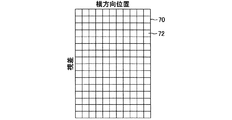
第1装置は、カメラセンサ11から出力された左画像信号及び右画像信号に基づいて、視差情報と、輝度値を含む画素情報と、を有する視差画像を生成する。視差画像を構成する各画素には視差情報及び画素情報が対応付けられている。第1装置は、衝突回避ECU10のRAMに、図3に示す視差投票マップ70を予め格納している。視差投票マップ70は、横方向の辺が視差画像の横方向(車幅方向)の位置に対応し、縦方向の辺が視差の大きさに対応するように定められた複数の矩形状のブロック72を配列させて構成されている。第1装置は、視差画像中の画素の位置及び当該画素の視差の大きさに基づいて、視差投票マップ70の対応するブロック72に画素を投票(分類)する。そして、第1装置は、視差投票マップ70の各ブロック72について、視差の平均値、視差の偏差、視差画像の縦方向における画素の座標の平均値及び視差画像の縦方向における画素の座標の偏差を算出する。
The first device generates a parallax image having parallax information and pixel information including a luminance value based on the left image signal and the right image signal output from the
第1装置は、視差投票マップ70の各ブロック72における画素の縦方向の分布(視差画像の縦方向における画素の座標の偏差)及び視差方向の分布(視差の偏差)に基づいて、各ブロック72の属性を障害物、路面及び不明の何れかに設定する。即ち、第1装置は、視差投票マップ70のブロック72内に、同程度の視差(距離)を有する画素が、視差画像の縦方向において広い範囲に分布している場合、当該画素の集合は障害物を示していると判定する。この場合、第1装置は、当該ブロック72の属性を障害物に設定し、当該ブロック72に分類された画素を障害物候補点として特定する。
Based on the vertical distribution of pixels in each
一方、第1装置は、視差投票マップ70のブロック72内に、同程度の視差(距離)を有する画素が、視差画像の縦方向における狭い範囲に分布し、視差が減少するにつれて(自車両からの距離が増大するにつれて)視差画像の縦方向における画素の位置が滑らかに上昇している場合、当該画素の集合は路面を示していると判定する。この場合、第1装置は、当該ブロック72の属性を路面に設定し、当該ブロック72に分類された画素を路面候補点として特定する。他方、第1装置は、障害物及び路面の何れの属性にも設定されなかったブロック72に不明の属性を設定し、当該ブロック72に分類された画素を不明候補点として特定する。なお、障害物候補点、路面候補点及び不明候補点に対応付けられている視差情報及び画素情報は、何れも「周辺情報」の一例に相当する。
On the other hand, the first device distributes pixels having the same degree of parallax (distance) in the
加えて、第1装置は、視差画像に含まれる画素情報に基づいて公知の手法を用いてエッジを検出し、エッジの視差画像を設定する。そして、白線や車線の規格に合ったエッジの組のみを選択することにより、白線を検出する。第1装置は、白線として検出された位置に存在する画素を白線候補点として特定する。なお、白線候補点に対応付けられている視差情報及び画素情報は、「周辺情報」の一例に相当する。 In addition, the first device detects an edge using a known method based on pixel information included in the parallax image, and sets the parallax image of the edge. A white line is detected by selecting only a pair of edges that meet the white line and lane standards. The first device identifies a pixel present at a position detected as a white line as a white line candidate point. Note that the parallax information and the pixel information associated with the white line candidate points correspond to an example of “peripheral information”.
グリッドマップ60の横方向の辺及び縦方向の辺は、それぞれ、視差画像の横方向の位置及び縦方向の位置(厳密には視差画像を平面視画像に変換したときの縦方向の位置)に対応している。単位領域62は、例えば、横25センチ×縦50センチの範囲に相当する領域である。図2において、自車両の先端における車幅方向の中心は、点64に位置している。各単位領域62は、初期状態において不明領域に設定されている。
The horizontal side and the vertical side of the
第1装置は、視差投票マップ70内の障害物候補点、路面候補点及び不明候補点と、エッジの視差画像内の白線候補点と、を、グリッドマップ60の対応する位置にプロットする。そして、第1装置は、グリッドマップ60の単位領域62内に障害物候補点が存在している場合、路面候補点、白線候補点及び不明候補点の存在有無に関わらず、当該単位領域62には障害物が存在していると判定して、当該単位領域を、不明領域から障害物領域に変更(特定)する。加えて、第1装置は、グリッドマップ60の単位領域62内に障害物候補点が存在しておらず、白線候補点が存在している場合、路面候補点及び不明候補点の存在有無に関わらず、当該単位領域62には白線が存在していると判定して、当該単位領域62を、不明領域から白線領域に変更(特定)する。更に、第1装置は、グリッドマップ60の単位領域62内に障害物候補点及び白線候補点が存在しておらず、路面候補点が存在している場合、不明候補点の存在有無に関わらず、当該単位領域62には路面が存在していると判定して、当該単位領域62を、不明領域から路面領域に変更(特定)する。更に、第1装置は、グリッドマップ60の単位領域62内に不明候補点しか存在していない場合、当該単位領域62は上記の障害物領域、白線領域及び路面領域の何れにも該当しないと判定して、当該単位領域62を不明領域に維持(特定)する。
The first device plots the obstacle candidate point, the road surface candidate point, and the unknown candidate point in the
ここで、路面領域の中には、自車両の走行路面として安全とは言えない単位領域(例えば、路面に自車両が安全に走行できない程度の窪みや傾斜面が形成されている領域)62が存在する可能性がある。加えて、不明領域の中には、自車両の走行路面として安全である単位領域62が存在する可能性がある。そこで、第1装置は、公知の手法を用いて、路面領域又は不明領域として特定された単位領域62内の画素(路面候補点又は不明候補点)に対応付けられている視差情報及び画素情報に基づいて、当該路面領域及び不明領域が自車両の走行路面として安全であるか否かを判定する。安全であると判定された場合、第1装置は、当該単位領域62は自車両の走行路面として安全であると判定して、当該単位領域62を路面領域又は不明領域から、安全領域に変更(特定)する。一方、安全ではないと判定された場合、第1装置は、当該単位領域62は自車両の走行路面として安全であるか否か不明であると判定して、当該単位領域62を路面領域又は不明領域から、不明領域に変更又は維持(特定)する。なお、「路面領域又は不明領域として特定された単位領域62内の画素(路面候補点又は不明候補点)に対応付けられている視差情報及び画素情報」は、「周辺情報」の一例に相当する。
Here, in the road surface region, there is a
このようにして、第1装置は、グリッドマップ60の各単位領域62を、障害物領域、白線領域、安全領域及び不明領域の何れかに分類する。単位領域62には、領域の種類に応じて異なるコストが設定される。このコストは、自車両が単位領域62に進入した場合の危険度を示す尺度であり、危険度が大きいほど高く設定される。障害物領域のコストは、自車両が障害物に接触する可能性があるため、最も高く設定される。白線領域のコストは、自車両が白線を越える(自車線を逸脱する)可能性があり、その結果、障害物に接触する可能性があるため、障害物領域のコストの次に高く設定される。不明領域のコストは、障害物や白線が存在する可能性は極めて低いものの、走行路面として安全かどうか不明なため、白線領域のコストの次に高く設定される。安全領域のコストは、ゼロに設定される。第1装置は、上記4種類の領域の何れかとして特定されたグリッドマップ60を衝突回避ECU10のRAMに格納する。RAMに格納されたグリッドマップ60は、演算周期毎に更新される。
In this way, the first device classifies each
<注意喚起>
第1装置は、エンジンオン期間中、演算周期毎に、自車両の進行方向前方に障害物が存在するか否かを判定する。具体的には、図4に示すように、第1装置は、グリッドマップ60において自車両の車幅方向の中心を表す点64から進行方向TDに延びる仮想直線66を設定し、当該仮想直線66が障害物領域を通過する場合、自車両の進行方向前方に障害物が存在すると判定する。この場合、第1装置は、自車両が現在の車速で走行を継続した場合に当該障害物に衝突するまでに要すると予測される時間である衝突予測時間TTC(Time To Collision)を算出する。TTCは、当該障害物までの距離を当該障害物に対する自車両の相対速度で除算することにより算出され得る。第1装置は、TTCが所定の時間閾値Tth0以下であり、且つ、時間閾値Tth0よりも小さい所定の時間閾値Tth1より大きい場合、自車両が当該障害物に衝突する可能性があると判定し、ブザー51を鳴動させてドライバに注意喚起する。時間閾値Tth0は注意喚起を行うか否かを決定する閾値である。注意喚起によりドライバがブレーキ操作を行い、その結果TTCが時間閾値Tth0よりも大きくなった場合、注意喚起は終了される。一方、注意喚起してもドライバがブレーキ操作を行わず、その結果TTCが時間閾値Tth1以下になった場合も、注意喚起は終了される。以下では、TTCが時間閾値Tth0以下の障害物を、特に「前方障害物」と称する。
<Awareness>
The first device determines whether there is an obstacle ahead of the traveling direction of the host vehicle for each calculation cycle during the engine-on period. Specifically, as shown in FIG. 4, the first device sets a virtual
<回避経路の設定>
図5A及び図5Bに示すように、第1装置は、前方障害物までのTTCが時間閾値Tth1以下になった場合、TTCが時間閾値Tth1よりも小さい所定の時間閾値Tth3になるまで、演算周期毎に、前方障害物との衝突を回避するための回避経路rA、rB(図5A及び図5Bに太線で示す。)を設定する。時間閾値Tth1は、回避経路rA、rBの設定を開始するか否かを決定する閾値であり、時間閾値Tth3は、回避経路rA、rBに沿った自動操舵制御を実行するか否かを判定するタイミングが到来したか否かを決定する閾値である。この回避経路rA、rBは、TTCが時間閾値Tth3になると予想される地点PA、PB(即ち、「前方障害物に対する現在の相対速度」に「時間閾値Tth3」を乗算した距離だけ前方障害物よりも手前の地点)から延びる経路である。別言すれば、自車両は地点PA、PBまでは直進すると想定されている。回避経路rA、rBを設定するに際し、第1装置は、前方障害物が連続障害物COであるか非連続障害物NCOであるかを判定し、判定結果に基づいて異なるパラメータを用いて回避経路rA、rBを設定する。なお、時間閾値Tth1は、「第1時間閾値」の一例に相当し、時間閾値Tth3は、「第3時間閾値」の一例に相当する。
<Setting avoidance route>
As shown in FIGS. 5A and 5B, when the TTC to the front obstacle becomes equal to or less than the time threshold Tth1, the first device operates until the TTC reaches a predetermined time threshold Tth3 smaller than the time threshold Tth1. Every time, avoidance routes r A and r B (indicated by bold lines in FIGS. 5A and 5B) for avoiding a collision with a front obstacle are set. The time threshold value Tth1 is a threshold value for determining whether to start setting the avoidance routes r A and r B , and the time threshold value Tth3 is whether or not the automatic steering control is performed along the avoidance routes r A and r B. This is a threshold value for determining whether or not the timing for determining whether or not has come. The avoidance paths r A and r B are only points P A and P B where the TTC is expected to become the time threshold Tth3 (that is, the “current relative speed with respect to the forward obstacle” multiplied by the “time threshold Tth3”). This is a route extending from the front obstacle). In other words, the host vehicle is assumed to go straight to the points P A and P B. When setting the avoidance routes r A and r B , the first device determines whether the front obstacle is a continuous obstacle CO or a non-continuous obstacle NCO, and uses different parameters based on the determination result. Avoidance routes r A and r B are set. The time threshold Tth1 corresponds to an example of “first time threshold”, and the time threshold Tth3 corresponds to an example of “third time threshold”.
まず、図6を参照して、前方障害物が連続性を有する連続障害物COであるのか、連続性を有さない非連続障害物NCOであるのかを判定する方法について説明する。図6に示すように、第1装置は、グリッドマップ60上に、所定の大きさを有する可動枠68を、前方障害物が存在する障害物領域Aが中心に位置するように配置する。例えば、この可動枠68は、横125センチ(単位領域5個分の長さ)×縦250センチ(単位領域5個分の長さ)の範囲に相当する。以下では、可動枠68の中心に位置する障害物領域Aを「中心障害物領域A」と称する。
First, referring to FIG. 6, a method for determining whether a forward obstacle is a continuous obstacle CO having continuity or a non-continuous obstacle NCO having no continuity will be described. As shown in FIG. 6, the first device arranges the
そして、第1装置は、可動枠68の範囲内で、中心障害物領域Aに近い単位領域62から順に障害物領域を探索していく。具体的には、中心障害物領域Aに隣接する8個の単位領域62の中から障害物領域を探索する。例えば、第1装置は、中心障害物領域Aの右上に位置する単位領域62urから反時計回りに障害物領域を探索する。8個の単位領域62の中に障害物領域が存在しない場合、第1装置は、当該8個の単位領域62にその外周側で隣接する16個の単位領域62の中から障害物領域を探索する。可動枠68の範囲に障害物領域が存在する場合、第1装置は、その障害物領域が新たな中心障害物領域Aとなるように可動枠68を移動させ、移動後の可動枠68の範囲内で障害物領域を探索する。このとき、既に中心障害物領域Aに設定された障害物領域は探索の対象から除外される。
Then, the first device searches for obstacle regions in order from the
第1装置は、このようにして可動枠68を移動させながら、障害物領域を探索する。可動枠68の範囲内に(現在および過去の中心障害物領域Aを除いて)障害物領域が存在しなくなった場合、第1装置は、これまでに中心障害物領域Aに設定された障害物領域同士を連結して、1つの連結領域80(図7参照)を作成する。このとき、障害物領域同士が隣接していなければ、その間に位置する単位領域62は連結領域80に含められる(例えば、図6の単位領域62a、62b、62cは連結領域80に含められる。)。
The first device searches for an obstacle region while moving the
連結領域80を作成したら、第1装置は、図7に示すように、連結領域80を長手方向に線形近似し、線形近似により得られた線分82の長さを算出する。そして、線分82の長さが所定の長さ閾値以上であるか否かを判定する。第1装置は、線分82の長さが長さ閾値以上であると判定した場合、連結領域80に存在する障害物は連続性を有する、即ち、連続障害物COであると判定する。一方、第1装置は、線分82の長さが長さ閾値未満であると判定した場合、連結領域80に存在する障害物は連続性を有さない、即ち、非連続障害物NCOであると判定する。長さ閾値は、ガードレール、側壁及び中央分離帯等が連続性を有すると判定され、車両、歩行者及び自転車等が連続性を有さないと判定される値に予め設定されている。
If the connection area |
次に、前方障害物が連続障害物COであると判定された場合の回避経路rAの設定方法について図5Aを参照して説明する。第1装置は、前方障害物が連続障害物COであると判定した場合、自車両の進行方向TDに延びる仮想直線66に対する連結領域80(図5Aでは図示省略)の線分82の傾きg[deg]を算出する。以下、当該傾きgを、単に「連続障害物の傾きg」とも称する。そして、連続障害物COの傾きgと、車速と、に基づいて回避経路rAを設定する。なお、傾きgには、自車両の進行方向TD(即ち、仮想直線66)と連結領域80の線分82とがなす2つの角度のうち鋭角の角度が採用される。傾きgの値は、連続障害物COが自車両に対して右斜め前方に延びている場合は正であり、連続障害物COが自車両に対して左斜め前方に延びている場合は負である。
Next, a method for setting the avoidance route r A when it is determined that the front obstacle is the continuous obstacle CO will be described with reference to FIG. 5A. When the first device determines that the front obstacle is the continuous obstacle CO, the slope g [of the
第1装置は、衝突回避ECU10のROMに、傾きg及び車速と、ヨーレートYと、の関係を規定するマップ(ヨーレートマップ)と、傾きg及び車速と、時間tと、の関係を規定するマップ(時間マップ)と、を予め格納している。ヨーレートマップは、自車両が連続障害物COとの衝突を回避するために必要なヨーレートYの情報を含む。時間マップは、自車両が連続障害物COとの衝突を回避するために、ヨーレートマップを参照して得られたヨーレートYで走行を継続すべき時間tの情報を含む。なお、ヨーレートマップのヨーレートYの値は、傾きgが正のときは正であり、傾きgが負のときは負に設定されている。
The first device stores, in the ROM of the
連続障害物COの傾きgと車速とを両マップにそれぞれ適用することにより、ヨーレートYと、当該ヨーレートYで走行する時間tとが一義的に決定される。これにより、回避経路rAの形状が一義的に決定される。即ち、「回避経路rAを設定すること」は、「連続障害物COの傾きg及び車速を上記2つのマップに適用してヨーレート及Yび時間tを決定すること」と同義である。なお、ここでいう車速とは、「地点PA(回避経路rAの開始地点)において推定される車速」である。この車速は、自動制動制御(後述)を実行する時点まで現在の車速が維持されると仮定すると、「現在の車速」と「自動制動制御(後述)による目標減速度」とから推定され得る。以下では、当該車速を現在の車速と区別するために「推定車速」と称する。 By applying the slope g and the vehicle speed of the continuous obstacle CO to both maps, the yaw rate Y and the time t during which the vehicle travels at the yaw rate Y are uniquely determined. Thus, the shape of the avoidance route r A is uniquely determined. That is, “setting the avoidance route r A ” is synonymous with “determining the yaw rate and the time t by applying the slope g and the vehicle speed of the continuous obstacle CO to the two maps”. The vehicle speed here is “the vehicle speed estimated at the point P A (the start point of the avoidance route r A )”. This vehicle speed can be estimated from “current vehicle speed” and “target deceleration by automatic braking control (described later)”, assuming that the current vehicle speed is maintained until a time point at which automatic braking control (described later) is executed. Hereinafter, the vehicle speed is referred to as “estimated vehicle speed” in order to distinguish it from the current vehicle speed.
ヨーレートマップでは、車速が一定の場合においては傾きgの絶対値が大きくなるほどヨーレートYの絶対値が大きくなり、傾きgが一定の場合においては車速が大きくなるほどヨーレートYの絶対値が大きくなるように設定されている。
一方、時間マップでは、車速が一定の場合においては傾きgの絶対値が大きくなるほど時間tが長くなり、傾きgが一定の場合においては車速が大きくなるほど時間tが長くなるように設定されている。
In the yaw rate map, when the vehicle speed is constant, the absolute value of the yaw rate Y increases as the absolute value of the gradient g increases. When the vehicle speed increases, the absolute value of the yaw rate Y increases as the vehicle speed increases. Is set.
On the other hand, in the time map, when the vehicle speed is constant, the time t becomes longer as the absolute value of the inclination g becomes larger, and when the inclination g is constant, the time t becomes longer as the vehicle speed becomes larger. .
なお、連続障害物COの傾きg及び車速には検出誤差に基づく誤差が生じる。このため、ヨーレートマップは、傾きg及び車速が演算周期によって誤差の範囲内で変化しても、ヨーレートYが一定の値を維持するように作成されている。時間マップについても同様である。 An error based on the detection error occurs in the inclination g of the continuous obstacle CO and the vehicle speed. For this reason, the yaw rate map is created so that the yaw rate Y maintains a constant value even if the inclination g and the vehicle speed change within the error range depending on the calculation cycle. The same applies to the time map.
第1装置は、回避経路rA(別言すれば、ヨーレートYと時間tの組み合わせ)を衝突回避ECU10のRAMに格納する。以下では、ヨーレートYと時間tの組み合わせを、単に「(Y,t)」とも称する。第1装置は、次の演算周期(以下、演算周期を単に「周期」とも称する。)においてもTTCが時間閾値Tth1以下の場合、前方障害物が連続障害物COであれば、上述したように連続障害物COの傾きgを算出し、傾きgと車速とに基づいてヨーレートYと時間tとを決定する。第1装置は、現在の周期における(Y,t)を、衝突回避ECU10のRAMに格納されている(Y,t)と比較し、同一であると判定した場合、回避経路rAに変更はないと判定する(即ち、RAMに格納されている(Y,t)を更新しない。)。一方、第1装置は、現在の周期における(Y,t)が衝突回避ECU10のRAMに格納されている(Y,t)と同一ではないと判定した場合、回避経路rAを新たに設定する(即ち、RAMに格納されている(Y,t)を現在の周期における(Y,t)に更新する。)。
The first device stores the avoidance route r A (in other words, the combination of the yaw rate Y and the time t) in the RAM of the
続いて、前方障害物が非連続障害物NCOであると判定された場合の回避経路rBの設定方法について図5Bを参照して説明する。前方障害物が非連続障害物NCOであると判定された場合、非連続障害物NCOは自車線内に存在している可能性が高い。このため、第1装置は、非連続障害物NCOと白線WL(自車線を構成する右側の右白線RWLと左側の左白線LWL)との間を通過する経路が設定可能か否かを判定し、設定可能と判定した場合に当該経路を回避経路rBとして設定する。 Next, a method for setting the avoidance route r B when it is determined that the front obstacle is a discontinuous obstacle NCO will be described with reference to FIG. 5B. When it is determined that the front obstacle is a discontinuous obstacle NCO, it is highly possible that the discontinuous obstacle NCO exists in the own lane. Therefore, the first device determines whether or not a route passing between the discontinuous obstacle NCO and the white line WL (the right white line RWL on the right side and the left white line LWL on the left side of the own lane) can be set. and sets the route when it is determined that can be set as a bypass route r B.
具体的には、第1装置は、視差情報に基づいて、自車両の車幅方向の中心を基準としたときの非連続障害物NCOの右端の位置と、右白線の左端の位置と、を特定し、両者の差分から非連続障害物NCOと右白線との横距離である右側横距離DRを算出する。同様に、第1装置は、非連続障害物NCOの左端の位置と、左白線の右端の位置と、を特定し、両者の差分から非連続障害物NCOと左白線との左側横距離DLを算出する。右側横距離DRは正の値として、左側横距離DLは負の値として算出される。 Specifically, the first device determines, based on the parallax information, the position of the right end of the discontinuous obstacle NCO and the position of the left end of the right white line when the center of the vehicle width direction of the host vehicle is used as a reference. identified, and calculates the right side distance D R is the horizontal distance between the discontinuous obstacle NCO and right white line from the difference between them. Similarly, the first device identifies the left end position of the discontinuous obstacle NCO and the right end position of the left white line, and the left lateral distance D L between the discontinuous obstacle NCO and the left white line is determined from the difference between the two. Is calculated. The right transverse distance D R as a positive value, the left transverse distance D L is calculated as a negative value.
第1装置は、右側横距離DRと、左側横距離DLの絶対値と、を比較し、大きい方の横距離の絶対値が、最小通過長さ以上であるか否かを判定する。ここで、最小通過長さは、「自車両の車幅長さW」に「所定の余裕幅(自車両が非連続障害物NCO及び白線WLとの間を余裕を持って通過するために最低限必要な幅)」を加算した長さとして定義される。大きい方の横距離の絶対値が最小通過長さ以上であると判定した場合、第1装置は、非連続障害物NCOと白線WLとの間を通過する回避経路rBが設定可能であると判定する。この場合、第1装置は、大きい方の横距離(以下、単に「横距離」とも称する。)に基づいて自車両が横方向に移動するべき距離である横移動距離LDを算出する。横移動距離LDは、横距離が正の場合(右側横距離DRの場合)、正の値として算出され、横距離が負の場合(左側横距離DLの場合)、負の値として算出される。そして、横移動距離LDと、車速と、に基づいて回避経路rBを設定する。一方、大きい方の横距離の絶対値が最小通過長さ未満であると判定された場合、第1装置は、非連続障害物NCOと白線WLとの間を通過する回避経路rBが設定不可能であると判定する。この場合、第1装置は、回避経路rBの設定を行わない(後述)。 The first device determines a right transverse distance D R, compares the absolute value of the left transverse distance D L, the absolute value of the lateral distance the larger, whether a minimum passage length or longer. Here, the minimum passing length is the “predetermined margin width (because the own vehicle passes between the non-continuous obstacle NCO and the white line WL with a margin) in the“ vehicle width length W of the own vehicle ”. Is defined as the length obtained by adding the “required width”). When it is determined that the absolute value of the larger lateral distance is greater than or equal to the minimum passage length, the first device can set an avoidance route r B that passes between the discontinuous obstacle NCO and the white line WL. judge. In this case, the first device calculates a lateral movement distance LD that is a distance that the host vehicle should move in the lateral direction based on the larger lateral distance (hereinafter, also simply referred to as “lateral distance”). Horizontal travel distance LD (if the right transverse distance D R) transverse distance is positive case, is calculated as a positive value, when the lateral distance is negative (in the case of the left lateral distance D L), calculated as a negative value Is done. Then, the avoidance route r B is set based on the lateral movement distance LD and the vehicle speed. On the other hand, if it is determined that the absolute value of the larger lateral distance is less than the minimum passage length, the first device does not set the avoidance route r B that passes between the discontinuous obstacle NCO and the white line WL. Determine that it is possible. In this case, the first device does not perform the setting of the bypass route r B (described later).
前方障害物が非連続障害物NCOの場合、回避経路rBは、まず、非連続障害物NCOとの衝突を回避し、その後、白線WLから逸脱することがない(自車線内にとどまる)形状となるように設定される。このため、回避経路rBは、「非連続障害物NCOとの衝突を回避するための経路rB1」と、「白線からの逸脱を阻止するための経路rB2」とが滑らかに接続された経路となる。以下では、前者の経路を「第1回避経路rB1」と称し、後者の経路を「第2回避経路rB2」と称する。第1回避経路rB1は、TTCが時間閾値Tth3になると予想される地点PBから延び、第2回避経路rB2は、第1回避経路rB1の終了地点から延びる経路となる。 When the forward obstacle is a non-continuous obstacle NCO, the avoidance path r B first avoids a collision with the non-continuous obstacle NCO, and then does not deviate from the white line WL (stays in the own lane). Is set to be For this reason, in the avoidance route r B , “route r B1 for avoiding collision with the non-continuous obstacle NCO” and “route r B2 for preventing deviation from the white line” are smoothly connected. It becomes a route. Hereinafter, the former route is referred to as “first avoidance route r B1 ”, and the latter route is referred to as “second avoidance route r B2 ”. The first avoidance route r B1 extends from the point P B where the TTC is expected to become the time threshold value Tth3, and the second avoidance route r B2 becomes a route extending from the end point of the first avoidance route r B1 .
第1装置は、衝突回避ECU10のROMに、第1回避経路rB1用の横移動距離LD及び車速と、ヨーレートYと、の関係を規定するマップ及び横移動距離LD及び車速と、時間tと、の関係を規定するマップと、第2回避経路rB2用の横移動距離LD及び車速と、ヨーレートYと、の関係を規定するマップ及び横移動距離LD及び車速と、時間tと、の関係を規定するマップと、を予め格納している。
以下、第1回避経路rB1用のヨーレートYと第2回避経路rB2用のヨーレートYとを区別するために、前者を「第1ヨーレートY1」と称し、後者を「第2ヨーレートY2」と称する。加えて、第1回避経路rB1用の時間tと第2回避経路rB2用の時間tとを区別するために、前者を「第1時間t1」と称し、後者を「第2時間t2」と称する。更に、第1ヨーレートY1のマップ及び第2ヨーレートY2のマップを、それぞれ「第1ヨーレートマップ」及び「第2ヨーレートマップ」と称し、第1時間t1のマップ及び第2時間t2のマップを、それぞれ「第1時間マップ」及び「第2時間マップ」と称する。
The first device stores in the ROM of the collision avoidance ECU 10 a map defining the relationship between the lateral movement distance LD and vehicle speed for the first avoidance route r B1 and the yaw rate Y, the lateral movement distance LD and vehicle speed, and the time t. , A map that defines the relationship between the lateral movement distance LD and vehicle speed for the second avoidance route r B2 , and the yaw rate Y, the lateral movement distance LD and vehicle speed, and the relationship between time t And a map that prescribes
Hereinafter, in order to distinguish the yaw rate Y for the first avoidance route r B1 and the yaw rate Y for the second avoidance route r B2 , the former is referred to as “first yaw rate Y1”, and the latter is referred to as “second yaw rate Y2”. Called. In addition, in order to distinguish the time t for the first avoidance route r B1 and the time t for the second avoidance route r B2 , the former is referred to as “first time t1” and the latter is referred to as “second time t2”. Called. Further, the map of the first yaw rate Y1 and the map of the second yaw rate Y2 are referred to as “first yaw rate map” and “second yaw rate map”, respectively, and the map of the first time t1 and the map of the second time t2 are respectively These are referred to as “first time map” and “second time map”.
第1ヨーレートマップは、自車両が非連続障害物NCOとの衝突を回避するために必要な第1ヨーレートY1の情報を含む。第1時間マップは、自車両が非連続障害物NCOとの衝突を回避するために、第1ヨーレートマップを参照して得られた第1ヨーレートY1で走行を継続すべき第1時間t1の情報を含む。第2ヨーレートマップは、非連続障害物NCOとの衝突回避後に自車両が白線から逸脱することを阻止するために必要な第2ヨーレートY2の情報を含む。第2時間マップは、自車両が白線から逸脱することを阻止するために、第2ヨーレートマップを参照して得られた第2ヨーレートY2で走行を継続すべき第2時間t2の情報を含む。なお、第1ヨーレートY1の値は、横移動距離LDが正のときは正であり、横移動距離LDが負のときは負に設定されている。一方、第2ヨーレートY2の値は、横移動距離LDが正のときは負であり、横移動距離LDが負のときは正に設定されている。 The first yaw rate map includes information on the first yaw rate Y1 necessary for the host vehicle to avoid a collision with the discontinuous obstacle NCO. The first time map is information on the first time t1 at which the vehicle should continue traveling at the first yaw rate Y1 obtained by referring to the first yaw rate map in order to avoid a collision with the discontinuous obstacle NCO. including. The second yaw rate map includes information on the second yaw rate Y2 necessary for preventing the vehicle from deviating from the white line after avoiding a collision with the discontinuous obstacle NCO. The second time map includes information on the second time t2 at which the vehicle should continue traveling at the second yaw rate Y2 obtained by referring to the second yaw rate map in order to prevent the host vehicle from deviating from the white line. The value of the first yaw rate Y1 is positive when the lateral movement distance LD is positive, and is negative when the lateral movement distance LD is negative. On the other hand, the value of the second yaw rate Y2 is negative when the lateral movement distance LD is positive, and is positive when the lateral movement distance LD is negative.
横移動距離LDと車速とを上記4種類のマップにそれぞれ適用することにより、第1ヨーレートY1と、当該第1ヨーレートY1で走行する第1時間t1と、第2ヨーレートY2と、当該第2ヨーレートY2で走行する第2時間t2と、が一義的に決定される。これにより、回避経路の形状が一義的に決定される。即ち、「回避経路rB(第1回避経路rB1及び第2回避経路rB2)を設定すること」は、「非連続障害物NCOと白線WLとの横距離に基づいて算出された横移動距離LD及び車速を上記4つのマップに適用して第1ヨーレートY1及び第1時間t1並びに第2ヨーレートY2及び第2時間t2を決定すること」と同義である。なお、ここでいう車速とは、「地点PB(回避経路rBの開始地点)において推定される車速」である。この車速は、自動制動制御(後述)を実行する時点まで現在の車速が維持されると仮定すると、「現在の車速」と「自動制動制御(後述)による目標減速度」とから推定され得る。以下では、当該車速を現在の車速と区別するために「推定車速」と称する。 By applying the lateral movement distance LD and the vehicle speed to the four types of maps, respectively, the first yaw rate Y1, the first time t1 that travels at the first yaw rate Y1, the second yaw rate Y2, and the second yaw rate. A second time t2 for traveling in Y2 is uniquely determined. Thereby, the shape of the avoidance path is uniquely determined. That is, “setting the avoidance route r B (first avoidance route r B1 and second avoidance route r B2 )” means that “the lateral movement calculated based on the lateral distance between the non-continuous obstacle NCO and the white line WL”. It is synonymous with “applying the distance LD and the vehicle speed to the above four maps to determine the first yaw rate Y1, the first time t1, the second yaw rate Y2, and the second time t2.” The vehicle speed here is “the vehicle speed estimated at the point P B (the start point of the avoidance route r B )”. This vehicle speed can be estimated from “current vehicle speed” and “target deceleration by automatic braking control (described later)”, assuming that the current vehicle speed is maintained until a time point at which automatic braking control (described later) is executed. Hereinafter, the vehicle speed is referred to as “estimated vehicle speed” in order to distinguish it from the current vehicle speed.
第1、第2ヨーレートマップでは、何れも、車速が一定の場合においては横移動距離LDの絶対値が大きくなるほど第1及び第2ヨーレートY1、Y2の絶対値が大きくなり、横移動距離LDが一定の場合においては車速が大きくなるほど第1及び第2ヨーレートY1、Y2の絶対値が大きくなるように設定されている。
一方、第1、第2時間マップでは、何れも、車速が一定の場合においては横移動距離LDの絶対値が大きくなるほど第1及び第2時間t1、t2が長くなり、横移動距離LDが一定の場合においては車速が大きくなるほど第1及び第2時間t1、t2が長くなるように設定されている。
In both the first and second yaw rate maps, when the vehicle speed is constant, the absolute values of the first and second yaw rates Y1 and Y2 increase as the absolute value of the lateral movement distance LD increases, and the lateral movement distance LD becomes smaller. In a fixed case, the absolute values of the first and second yaw rates Y1, Y2 are set to increase as the vehicle speed increases.
On the other hand, in both the first and second time maps, when the vehicle speed is constant, as the absolute value of the lateral movement distance LD increases, the first and second times t1 and t2 become longer and the lateral movement distance LD becomes constant. In this case, the first and second times t1 and t2 are set longer as the vehicle speed increases.
なお、横移動距離LD及び車速には検出誤差に基づく誤差が生じる。このため、第1、第2ヨーレートマップは、何れも、横移動距離LD及び車速が演算周期によって誤差の範囲内で変化しても、第1及び第2ヨーレートY1、Y2がそれぞれ一定の値を維持するように作成されている。第1、第2時間マップについても同様である。 An error based on a detection error occurs in the lateral movement distance LD and the vehicle speed. For this reason, in both the first and second yaw rate maps, even if the lateral movement distance LD and the vehicle speed change within the error range depending on the calculation cycle, the first and second yaw rates Y1 and Y2 each have a constant value. Created to maintain. The same applies to the first and second time maps.
第1装置は、回避経路rB(別言すれば、第1ヨーレートY1と第1時間t1の組み合わせと、第2ヨーレートY2と第2時間t2の組み合わせ)を衝突回避ECU10のRAMに格納する。以下では、前者の組み合わせを単に(Y1,t1)とも称し、後者の組み合わせを単に(Y2,t2)とも称する。第1装置は、次の演算周期においてもTTCが時間閾値Tth1以下の場合、前方障害物が非連続障害物NCOであれば、上述したように横移動距離LDを算出し、横移動距離LDと車速とに基づいて第1回避経路rB1用の第1ヨーレートY1及び第1時間t1と、第2回避経路rB2用の第2ヨーレートY2と第2時間t2とを決定する。第1装置は、現在の周期における(Y1,t1)及び(Y2,t2)を、衝突回避ECU10のRAMに格納されている(Y1,t1)及び(Y2,t2)とそれぞれ比較し、何れも同一であると判定した場合、回避経路rBに変更はないと判定する(即ち、RAMに格納されている(Y1,t1)及び(Y2,t2)を更新しない。)。一方、第1装置は、現在の周期における(Y1,t1)及び(Y2,t2)の少なくとも一方が衝突回避ECU10のRAMに格納されている(Y1,t1)及び(Y2,t2)と同一ではないと判定した場合、回避経路rBを新たに設定する(即ち、RAMに格納されている(Y1,t1)及び(Y2,t2)を現在の周期における(Y1,t1)及び(Y2,t2)に更新する。)。
The first device stores the avoidance route r B (in other words, the combination of the first yaw rate Y1 and the first time t1, and the combination of the second yaw rate Y2 and the second time t2) in the RAM of the
<信頼度の算出>
第1装置は、回避経路rA又はrBが設定された場合、演算周期毎に当該回避経路rA又はrBの信頼度を算出する。ここで、信頼度とは、回避経路rA又はrBが安全な走行経路であるか否かを示す尺度である。信頼度の算出方法は回避経路rA又はrBの種類によらず同一であるため、以下では、図8を参照して、回避経路rAの信頼度の算出方法を具体的に説明する。なお、図8では、回避領域RAの近傍のグリッドマップ60のみを図示しており、連続障害物COの図示は省略している。
<Calculation of reliability>
When the avoidance route r A or r B is set, the first device calculates the reliability of the avoidance route r A or r B for each calculation cycle. Here, the reliability is a scale indicating whether or not the avoidance route r A or r B is a safe travel route. Since the calculation method of the reliability is the same regardless of the type of the avoidance route r A or r B , the calculation method of the reliability of the avoidance route r A will be specifically described below with reference to FIG. In FIG. 8, only the
上述した方法で設定された回避経路rAをグリッドマップ60上に配置すると、回避経路rAは、点65(グリッドマップ60における地点PA(TTCが時間閾値Tth3になると予想される地点)に対応する点)から延びることになる。第1装置は、グリッドマップ60上において、回避経路rAを、点65から「半車幅長W/2に所定の第1距離α1を加算した長さW/2+α1」だけ車幅方向右側に平行移動した右側回避経路rARを設定するとともに、回避経路rAを、点65から「半車幅長W/2に所定の第2距離α2を加算した長さW/2+α2」だけ車幅方向左側に平行移動した左側回避経路rALを設定する。第1装置は、右側回避経路rARと左側回避経路rALの間の領域を回避領域RAとして設定する。即ち、回避領域RAは、自車両が回避経路rAに沿って走行したときに自車両が通過する領域を少なくとも含む領域である。なお、第1距離α1と第2距離α2は同一でもよいし、異なっていてもよい。
When the avoidance path r A which is set by the method described above is placed on the
上述したように、グリッドマップ60の単位領域62は、異なるコストを有する4種類の領域(障害物領域、白線領域、不明領域及び安全領域)に分類されている。第1装置は、演算周期毎に、回避領域RA内に存在する全ての単位領域62のコストを積算し、その積算値を回避領域コストCAとして算出する。なお、単位領域62の一部のみが回避領域RA内に存在する場合、当該単位領域62は回避領域RA内に存在するとみなされる。
障害物領域、白線領域、不明領域及び安全領域のコストをそれぞれC1、C2、C3及びC4とし(C1>C2>C3>C4=0)、回避領域RA内に存在する障害物領域、白線領域、不明領域及び安全領域の個数をそれぞれn1、n2、n3及びn4とすると、回避領域コストCAは、CA=C1n1+C2n2+C3n3として算出される。図8Aの例では、回避領域RA内には、障害物領域が2個、白線領域が1個、不明領域が3個存在している。このため、回避領域コストCAは、CA=2C1+C2+3C3として算出される。即ち、回避領域コストCAは、自車両が回避経路rAに沿って回避領域RA内を走行した場合の危険度を示す尺度であり、回避領域コストCAが高いほど危険度が大きいことを示す。
回避経路rBの回避領域RBの回避領域コストCBについても、上記と同一の方法で算出され得る。
As described above, the
The cost of the obstacle area, white line area, unknown area and safety area is C1, C2, C3 and C4 (C1>C2>C3> C4 = 0), respectively, and the obstacle area and white line area existing in the avoidance area RA If the numbers of unknown areas and safety areas are n1, n2, n3 and n4, respectively, the avoidance area cost C A is calculated as C A = C1n1 + C2n2 + C3n3. In the example of FIG. 8A, there are two obstacle areas, one white line area, and three unknown areas in the avoidance area RA . Therefore, the avoidance area cost C A is calculated as C A = 2C1 + C2 + 3C3. That is, avoidance region cost C A is a measure of the risk in the case of traveling the vehicle is avoided in the region R A along the avoidance path r A, avoidance region cost C A is larger the higher the risk Indicates.
For even avoidance region cost C B avoidance region R B of the bypass route r B, it can be calculated in the same way.
第1装置は、演算周期毎に、回避領域コストCA又はCBが所定のコスト閾値以上であるか否かを判定する。回避領域コストCA又はCBが所定のコスト閾値以上の場合、第1装置は、自車両が回避領域RA又はRB内を走行するのは危険である(別言すれば、回避経路rA又はrBは走行経路として安全ではない)と判定する。この場合、現在の周期における回避経路rA又はrBが、衝突回避ECU10のRAMに格納されている回避経路rA又はrBと同一であれば、第1装置は、直前の周期における信頼度から所定の値を減算した値を現在の周期における信頼度として算出する。なお、第1装置は、衝突回避ECU10のROMに、信頼度の初期値を予め格納している。このため、現在の周期が、ある前方障害物に対する回避経路rA又はrBを初めて設定した周期である初回周期であれば、第1装置は、回避領域コストCA又はCBが所定のコスト閾値以上の場合、信頼度の初期値から所定の値を減算した値を現在の周期における信頼度として算出する。
The first device determines whether the avoidance area cost C A or C B is greater than or equal to a predetermined cost threshold value for each calculation cycle. When the avoidance area cost C A or C B is equal to or greater than a predetermined cost threshold, the first device is dangerous for the host vehicle to travel in the avoidance area R A or R B (in other words, the avoidance route r A or r B is not safe as a travel route). In this case, the avoidance route r A or r B in the current cycle, if the same as the avoidance path r A or r B are stored in the collision avoidance ECU10 of RAM, the first device, confidence in the previous period A value obtained by subtracting a predetermined value from is calculated as the reliability in the current cycle. The first device stores the initial reliability value in advance in the ROM of the
一方、回避領域コストCA又はCBが所定のコスト閾値未満の場合、第1装置は、自車両が回避領域RA又はRB内を走行するのは安全である(別言すれば、回避経路rA又はrBは走行経路として安全である)と判定する。この場合、現在の周期における回避経路rA又はrBがRAMに格納されている回避経路rA又はrBと同一であれば、第1装置は、直前の周期における信頼度に所定の値を加算した値を現在の周期における信頼度として算出する。加えて、現在の周期が初回周期であれば、第1装置は、回避領域コストCA又はCBが所定のコスト閾値未満の場合、信頼度の初期値に所定の値を加算した値を現在の周期における信頼度として算出する。
即ち、複数の周期を含むある期間に亘って回避経路rA又はrBが同一であり、且つ、回避領域コストCA又はCBがコスト閾値未満の状態が継続すれば、当該回避経路rA又はrBの信頼度は増加し続ける。一方、複数の周期を含むある期間に亘って回避経路rA又はrBが同一であり、且つ、回避領域コストCA又はCBがコスト閾値以上の状態が継続すれば、当該回避経路rA又はrBの信頼度は減少し続ける。
On the other hand, when the avoidance area cost C A or C B is less than the predetermined cost threshold, the first device is safe for the host vehicle to travel in the avoidance area R A or R B (in other words, avoidance It determines that the route r a or r B is safe as a travel route). In this case, if the same as the avoidance path r A or r B avoided in the current cycle route r A or r B is stored in the RAM, the first device, the predetermined value to the reliability of the previous period The added value is calculated as the reliability in the current cycle. In addition, if the current cycle is the initial cycle, the first device, when the avoidance area cost C A or C B is less than a predetermined cost threshold, adds a value obtained by adding a predetermined value to the initial value of reliability. It is calculated as the reliability in the period.
That is, if the avoidance path r A or r B is the same over a certain period including a plurality of periods and the avoidance area cost C A or C B is less than the cost threshold, the avoidance path r A Or the reliability of r B continues to increase. On the other hand, if the avoidance path r A or r B is the same over a certain period including a plurality of cycles and the avoidance area cost C A or C B continues to be equal to or higher than the cost threshold, the avoidance path r A Or the reliability of r B continues to decrease.
他方、現在の周期における回避経路rA又はrBが、RAMに格納されている回避経路rA又はrBと異なる場合、第1装置は、直前の演算周期における信頼度をリセットして初期値に設定し、新たな回避経路rA又はrBの信頼度の算出を開始する。
第1装置は、信頼度の算出を、TTCが減少して時間閾値Tth3に等しくなるまで行う。第1装置は、上述した方法で算出された信頼度を、衝突回避ECU10のRAMに格納する。RAMに格納される信頼度は、演算周期毎に更新される。
On the other hand, the avoidance route r A or r B in the current cycle, if different from the avoidance path r A or r B are stored in the RAM, the first device resets the reliability in the operation period of the immediately preceding initial value And the calculation of the reliability of the new avoidance route r A or r B is started.
The first device calculates the reliability until TTC decreases and becomes equal to the time threshold value Tth3. The first device stores the reliability calculated by the above-described method in the RAM of the
<自動制動制御>
第1装置は、TTCが時間閾値Tth1から減少して、時間閾値Tth3よりも大きい所定の時間閾値Tth2(Tth3<Tth2<Tth1)以下になった場合、自車両が前方障害物に衝突する可能性がやや高いと判定し、自車両に制動力を自動的に付与する自動制動制御を実行する。時間閾値Tth2は、「自動制動制御のみで前方障害物との衝突回避を理論上実現できること」と、「ドライバの運転操作(典型的には、操舵ハンドル操作)と干渉しないこと(別言すれば、ドライバが自動制動制御を不要作動だと感じないこと)」とを両立できる値に設定される。この値は、前方障害物に対する相対速度及び周囲環境等に応じて変化する値であり、相対速度及び周囲環境を表すパラメータにより演算周期毎に設定される。なお、時間閾値Tth2は、「第2時間閾値」の一例に相当する。
<Automatic braking control>
In the first device, when the TTC decreases from the time threshold value Tth1 and falls below a predetermined time threshold value Tth2 (Tth3 <Tth2 <Tth1) larger than the time threshold value Tth3, there is a possibility that the host vehicle collides with a forward obstacle. It is determined that the vehicle is slightly high, and automatic braking control that automatically applies braking force to the host vehicle is executed. The time threshold value Tth2 is that “a collision avoidance with a front obstacle can be theoretically realized only by automatic braking control” and “a driver's driving operation (typically, steering wheel operation) does not interfere (in other words, The driver does not feel that the automatic braking control is an unnecessary operation) ”. This value is a value that changes according to the relative speed with respect to the front obstacle, the surrounding environment, and the like, and is set for each calculation cycle by a parameter representing the relative speed and the surrounding environment. The time threshold value Tth2 corresponds to an example of “second time threshold value”.
<自動操舵制御の実行有無判定>
自動制動制御を実行しても、路面状態及び/又は前方障害物が減速した等の要因によりTTCが時間閾値Tth2からさらに減少する場合がある。第1装置は、TTCが減少して時間閾値Tth3(<Tth2)になった場合、自車両が前方障害物に衝突する可能性が高いと判定し、上述した方法で設定された回避経路rA又はrBに沿って自車両が走行するように自車両の操舵輪の転舵角を自動的に変更する自動操舵制御を実行するか否かを判定する。上述したように、第1装置は、TTCが時間閾値Tth3に等しくなるまで、演算周期毎に回避経路rA又はrBの信頼度を算出し、その値を更新する。即ち、第1装置は、自動制動制御が開始されてからも、自動操舵制御を実行するか否かを判定するタイミング(TTC=Tth3)が到来するまで、回避経路の信頼度を算出(更新)する。
<Determining whether automatic steering control is performed>
Even if the automatic braking control is executed, the TTC may further decrease from the time threshold value Tth2 due to a road surface condition and / or a forward obstacle decelerating. When the TTC decreases and becomes the time threshold value Tth3 (<Tth2), the first device determines that the host vehicle is highly likely to collide with a forward obstacle, and the avoidance route r A set by the above-described method. or determining whether the vehicle along the r B automatically executes automatic steering control for changing the steering angle of steered wheels of the vehicle so that the vehicle travels. As described above, the first device calculates the reliability of the avoidance route r A or r B for each calculation cycle and updates the value until the TTC becomes equal to the time threshold value Tth3. That is, the first device calculates (updates) the reliability of the avoidance route until the timing (TTC = Tth3) for determining whether or not to execute the automatic steering control comes after the automatic braking control is started. To do.
第1装置は、TTCが時間閾値Tth3になった場合、回避経路rA又はrBの信頼度が所定の信頼度閾値(回避経路rA又はrBが走行経路として安全であるか否かを決定する閾値)以上であるか否かを判定する。回避経路rA又はrBの信頼度が信頼度閾値以上であると判定された場合、第1装置は、当該回避経路rA又はrBは自車両の走行経路として安全であると判定する。しかしながら、第1装置は、回避経路rA又はrBが安全な走行経路であると判定された場合に、常に当該回避経路rA又はrBに沿うように自車両を自動操舵するわけではない。 When the TTC reaches the time threshold value Tth3, the first device determines whether the reliability of the avoidance route r A or r B is a predetermined reliability threshold value (whether the avoidance route r A or r B is safe as a travel route). It is determined whether or not it is equal to or greater than a threshold value to be determined. If the reliability of the avoidance route r A or r B is determined to be confidence threshold or more, it is determined that the first device, the avoidance path r A or r B is safe as a travel route of the vehicle. However, the first device, when the avoidance route r A or r B is determined to be safe travel route, does not always automatically steer the vehicle along the said avoidance path r A or r B .
第1装置は、TTC=Tth3である演算周期において、以下の3つの条件、即ち、
・回避経路rA又はrBの信頼度が所定の信頼度閾値以上である。
・自動制御制御が実行されている。
・自動制動制御の減速度と車速とに基づく制動距離が、前方障害物までの距離よりも長い(即ち、自動制動制御のみでは前方障害物との衝突を回避できない。)。
が全て成立した場合、自動操舵制御を実行するための特定条件が成立したと判定し、上述した方法で設定された回避経路rA又はrBに沿って自車両が走行するように自車両を自動操舵制御する。一方、第1装置は、3つの条件の少なくとも1つが成立しない場合、特定条件が成立しないと判定し自動操舵制御を実行しない。この場合、TTC≦Tth2が成立した時点で開始された自動制動制御が引き続き実行される。
The first device has the following three conditions in the calculation cycle where TTC = Tth3:
The reliability of the avoidance route r A or r B is greater than or equal to a predetermined reliability threshold value.
• Automatic control is being executed.
The braking distance based on the deceleration of the automatic braking control and the vehicle speed is longer than the distance to the front obstacle (that is, the collision with the front obstacle cannot be avoided only by the automatic braking control).
If all of the above are satisfied, it is determined that the specific condition for executing the automatic steering control is satisfied, and the host vehicle is moved so that the host vehicle travels along the avoidance route r A or r B set by the method described above. Automatic steering control. On the other hand, if at least one of the three conditions is not satisfied, the first device determines that the specific condition is not satisfied and does not execute the automatic steering control. In this case, the automatic braking control started when TTC ≦ Tth2 is established is continued.
上記の特定条件から明らかなように、自動操舵制御は、自動制動制御とともに実行される。加えて、自動操舵制御は、自動制動制御のみでは前方障害物との衝突を回避できないと判定された場合に実行される。別言すれば、自動制動制御のみで衝突回避できると判定された場合は、たとえ回避経路rA又はrBの信頼度が信頼度閾値以上であったとしても当該回避経路rA又はrBに沿った自動操舵制御は実行されない。更に、自動制動制御のみでは衝突回避できないと判定された場合であっても、回避経路rA又はrBの信頼度が信頼度閾値未満であれば、当該回避経路rA又はrBに沿った自動操舵制御は実行されない。なお、信頼度の初期値は、信頼度閾値よりも低く設定される。このため、前方障害物が非連続障害物の場合において横距離が最小通過長さ未満であるために回避経路rA又はrBが設定不可能と判定されたときは、信頼度が算出されない(初期値に維持される)ので特定条件が成立せず、従って、自動操舵制御は実行されない。 As is clear from the above specific conditions, the automatic steering control is executed together with the automatic braking control. In addition, the automatic steering control is executed when it is determined that the collision with the front obstacle cannot be avoided only by the automatic braking control. In other words, if it is determined that the collision can be avoided only by the automatic braking control, even if the reliability of the avoidance route r A or r B is equal to or higher than the reliability threshold, the avoidance route r A or r B The automatic steering control along is not executed. Furthermore, even if it is determined that collision cannot be avoided only by the automatic braking control, if the reliability of the avoidance route r A or r B is less than the reliability threshold value, the avoidance route r A or r B is followed. Automatic steering control is not executed. Note that the initial value of the reliability is set lower than the reliability threshold. For this reason, when the front obstacle is a discontinuous obstacle, the reliability is not calculated when it is determined that the avoidance route r A or r B cannot be set because the lateral distance is less than the minimum passage length ( Therefore, the specific condition is not satisfied, and therefore the automatic steering control is not executed.
(第1装置の制御フロー)
次に、第1装置の制御フローについて説明する。第1装置の衝突回避ECU10(以下、単に「ECU10」とも称する。)のCPUは、エンジンオン期間中、図9A乃至図11Bにフローチャートにより示したルーチンを演算時間の経過毎に実行するようになっている。
(Control flow of the first device)
Next, the control flow of the first device will be described. The CPU of the collision avoidance ECU 10 (hereinafter also simply referred to as “
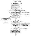
CPUは、所定のタイミングになると、図9Aのステップ900から処理を開始して以下のステップ902乃至ステップ908の処理を順に行う。
ステップ902:CPUは、カメラセンサ11から左画像信号及び右画像信号を受信する。即ち、左画像及び右画像を含む撮像画像を取得し、ECU10のRAMに格納する。
ステップ904:CPUは、車両状態センサ12から車両状態情報(車速、前後方向及び左右方向加速度、ヨーレート及び転舵角等)を取得し、ECU10のRAMに格納する。
ステップ906:CPUは、ステップ902で取得した撮像画像から視差画像を生成し、ECU10のRAMに格納する。
ステップ908:CPUは、上述したようにして、ECU10のRAMに格納されているグリッドマップ60の単位領域62を、4種類の領域(障害物領域、白線領域、不明領域及び安全領域)の何れかの領域として特定し、ECU10のRAMに格納する。
At a predetermined timing, the CPU starts processing from
Step 902: The CPU receives a left image signal and a right image signal from the
Step 904: The CPU acquires vehicle state information (vehicle speed, longitudinal and lateral acceleration, yaw rate, turning angle, etc.) from the
Step 906: The CPU generates a parallax image from the captured image acquired in
Step 908: As described above, the CPU selects one of the four types of areas (obstacle area, white line area, unknown area, and safety area) as the
次いで、CPUは、ステップ910に進んで、ステップ908で作成されたグリッドマップ60を参照して、上述したようにして自車両の進行方向前方に障害物が存在するか否かを判定する。障害物が存在しないと判定した場合、CPUは、ステップ910にて「No」と判定し(即ち、衝突回避の対象になり得る障害物が存在しないと判定し)、図9Bのステップ942に進み、本ルーチンを一旦終了する。
一方、障害物が存在すると判定した場合、CPUは、ステップ910にて「Yes」と判定し(即ち、衝突回避の対象になり得る障害物が存在すると判定し)、以下のステップ912に進む。
Next, the CPU proceeds to step 910 and refers to the
On the other hand, if it is determined that there is an obstacle, the CPU determines “Yes” in step 910 (ie, determines that there is an obstacle that can be a collision avoidance target), and proceeds to the following
ステップ912では、CPUは、ステップ910で自車両の進行方向前方に存在すると判定された障害物までのTTCを算出し、当該TTCが、時間閾値Tth0以下であるか否かを判定する。なお、時間閾値Tth0は、注意喚起を行うか否かを決定する閾値である。TTC≦Tth0が成立しない(即ち、TTC>Tth0)と判定した場合、CPUは、ステップ912にて「No」と判定し(即ち、前方障害物と衝突する可能性は極めて低く、注意喚起を行うタイミングはまだ到来していないと判定し)、図9Bのステップ942に進み、本ルーチンを一旦終了する。
一方、TTC≦Tth0が成立すると判定した場合、CPUは、ステップ912にて「Yes」と判定し(即ち、前方障害物と衝突する可能性があると判定し)、以下のステップ914に進む。
In
On the other hand, if it is determined that TTC ≦ Tth0 is established, the CPU determines “Yes” in step 912 (ie, determines that there is a possibility of colliding with a front obstacle), and proceeds to the following
ステップ914では、CPUは、前方障害物までのTTCが時間閾値Tth1以下であるか否かを判定する。なお、時間閾値Tth1は、回避経路rA又はrBの設定を開始するか否かを決定する閾値である。TTC≦Tth1が成立しない(即ち、TTC>Tth1)と判定した場合、CPUは、ステップ914にて「No」と判定し(即ち、回避経路rA又はrBの設定を開始するタイミングはまだ到来していないと判定し)、以下のステップ916の処理を行う。
In
ステップ916:CPUは、前方障害物に対する注意喚起要求信号を発生し、当該信号を警報ECU50に送信する。これにより、ブザー51によってドライバへの注意喚起が行われる。即ち、ステップ916の処理は、TTCがTth1<TTC≦Tth0を満たす場合に行われる。
Step 916: The CPU generates a warning request signal for the front obstacle, and transmits the signal to the
これに対し、ステップ914にてTTC≦Tth1が成立すると判定した場合、CPUは、ステップ914にて「Yes」と判定し(即ち、回避経路rA又はrBの設定を開始するタイミングが到来したと判定し)、以下のステップ922に進む。
On the other hand, if it is determined in
ステップ922では、CPUは、回避経路rA又はrBの設定を開始する。回避経路rA又はrBを設定するに際し、CPUは、前方障害物が連続性を有するか否かを判定する。具体的には、CPUは、グリッドマップ60において、前方障害物が存在する障害物領域を含む連結領域80を線形近似して線分82を算出する。そして、線分82の長さが長さ閾値以上であるか否かを判定する。長さ閾値以上であると判定した場合、CPUは、前方障害物が連続性を有する連続障害物COであると判定し、ステップ922にて「Yes」と判定し、以下のステップ924に進む。
In
図9Aのルーチンでは、CPUは、ステップ924において、図10にフローチャートにより示したルーチンを実行するようになっている。CPUは、ステップ924に進むと、図10のステップ1000から処理を開始し、以下に述べるステップ1002及びステップ1004の処理を順に行う。
In the routine of FIG. 9A, the CPU executes the routine shown in the flowchart of FIG. When the CPU proceeds to step 924, the CPU starts processing from
ステップ1002:CPUは、ステップ922にて算出された、「連結領域80を線形近似して得られた線分82」の傾きgを算出し、ECU10のRAMに格納する。
ステップ1004:CPUは、ECU10のROMに予め格納されているヨーレートマップ及び時間マップのそれぞれに、ステップ1002にて算出された傾きgと、図9Aのステップ904にて取得された車速及び目標減速度に基づいて算出された推定車速と、を適用して、ヨーレートYと時間tを決定する。
Step 1002: The CPU calculates an inclination g of “a
Step 1004: The CPU adds the slope g calculated in
次いで、CPUは、ステップ1006に進み、現在の演算周期(以下、単に「周期」とも称する。)が初回周期であるか否かを判定する。ここで、初回周期とは、ある前方障害物に対する回避経路rA又はrBが初めて設定された周期である。別言すれば、ある前方障害物までのTTCについて、TTC≦Tth1が初めて成立したと判定された周期である。現在の周期が初回周期であると判定した場合、CPUは、ステップ1006にて「Yes」と判定し(即ち、回避経路rAはステップ1004にて決定された(Y,t)に基づいて設定されると判定し)、以下のステップ1008及びステップ1010の処理を行う。
Next, the CPU proceeds to step 1006 to determine whether or not the current calculation cycle (hereinafter also simply referred to as “cycle”) is the initial cycle. Here, the initial period is a period in which the avoidance route r A or r B for a certain forward obstacle is set for the first time. In other words, it is a cycle in which it was determined that TTC ≦ Tth1 was established for the first time with respect to TTC up to a certain forward obstacle. If it is determined that the current cycle is the first cycle, the CPU determines “Yes” in step 1006 (that is, the avoidance route r A is set based on (Y, t) determined in step 1004). And the following processing of
ステップ1008:CPUは、現在の周期におけるステップ1004にて決定された(Y,t)に基づいて、上述したようにしてグリッドマップ60上で回避領域RAを設定する。CPUは、当該(Y,t)及び回避領域RAの形状をECU10のRAMに格納する。
ステップ1010:CPUは、ステップ1008にて設定された回避領域RAについて、上述したようにして回避領域コストCAを算出し、ECU10のRAMに格納する。
Step 1008: The CPU sets the avoidance area RA on the
Step 1010: CPU, for avoidance region R A set in
次いで、CPUは、ステップ1012に進んで、ステップ1010にて算出された回避領域コストCAがコスト閾値以上であるか否かを判定する。回避領域コストCAがコスト閾値以上であると判定した場合、CPUは、ステップ1012にて「Yes」と判定し(即ち、自車両が回避領域RA内を走行するのは危険であると判定し)、以下のステップ1014の処理を行う。
Then, CPU proceeds to step 1012, avoidance region cost C A calculated in
ステップ1014:CPUは、現在の周期における回避経路rAの信頼度を算出する。具体的には、CPUは、当該信頼度を、予めECU10のROMに格納されている初期値から所定値を減算した値として算出する。CPUは、当該信頼度をECU10のRAMに格納し、その後、ステップ1030を経由して、図9Aのステップ928(後述)に進む。
Step 1014: The CPU calculates the reliability of the avoidance route r A in the current cycle. Specifically, the CPU calculates the reliability as a value obtained by subtracting a predetermined value from an initial value stored in advance in the ROM of the
一方、ステップ1012にて回避領域コストCAがコスト閾値未満であると判定した場合、CPUは、ステップ1012にて「No」と判定し(即ち、自車両が回避領域RA内を走行するのは安全であると判定し)、以下のステップ1016の処理を行う。
On the other hand, if it is determined that the avoidance region cost C A in
ステップ1016:CPUは、現在の周期における回避経路rAの信頼度を算出する。具体的には、CPUは、当該信頼度を、予めECU10のROMに格納されている初期値に所定値を加算した値として算出する。CPUは、当該信頼度をECU10のRAMに格納し、その後、ステップ1030を経由して、図9Aのステップ928(後述)に進む。
Step 1016: The CPU calculates the reliability of the avoidance route r A in the current cycle. Specifically, the CPU calculates the reliability as a value obtained by adding a predetermined value to an initial value stored in advance in the ROM of the
これに対し、ステップ1006にて現在の周期が初回周期ではないと判定した場合、CPUは、ステップ1006にて「No」と判定し、以下のステップ1018に進む。
On the other hand, if it is determined in
ステップ1018では、CPUは、現在の周期におけるステップ1004にて決定された(Y,t)が、RAMに格納されている(Y,t)と同一であるか否かを判定する。同一であると判定した場合、CPUは、ステップ1018にて「Yes」と判定し(即ち、回避経路rA及び回避領域RAは、直前の周期から変更しないと判定し)、RAMに格納されている(Y,t)を変更しない。その後、CPUは、以下のステップ1020の処理を行う。
In step 1018, the CPU determines whether (Y, t) determined in
ステップ1020:CPUは、ECU10のRAMに格納されている回避領域RA(即ち、以前の周期においてステップ1008にて設定された回避領域RA)について、上述したようにして回避領域コストCAを算出し、ECU10のRAMに格納する。なお、回避領域コストCAの算出は、現在の周期におけるステップ908(図9A参照)にて作成されたグリッドマップ60上で行われる。
Step 1020: CPU is avoidance region R A (i.e., avoidance region R A set in
次いで、CPUは、ステップ1022に進んで、ステップ1020にて算出された回避領域コストCAがコスト閾値以上であるか否かを判定する。回避領域コストCAがコスト閾値以上であると判定した場合、CPUは、ステップ1022にて「Yes」と判定し(即ち、自車両が回避領域RA内を走行するのは危険であると判定し)、以下のステップ1024の処理を行う。
Then, CPU proceeds to step 1022, avoidance region cost C A calculated in
ステップ1024:CPUは、現在の周期における回避経路rAの信頼度を算出する。具体的には、CPUは、当該信頼度を、直前の周期における信頼度から所定値を減算した値として算出する。なお、当該信頼度は、ECU10のRAMに格納されている。CPUは、当該信頼度をECU10のRAMに格納し、その後、ステップ1030を経由して、図9Aのステップ928(後述)に進む。
Step 1024: The CPU calculates the reliability of the avoidance route r A in the current cycle. Specifically, the CPU calculates the reliability as a value obtained by subtracting a predetermined value from the reliability in the immediately preceding cycle. The reliability is stored in the RAM of the
一方、ステップ1022にて回避領域コストCAがコスト閾値未満であると判定した場合、CPUは、ステップ1022にて「No」と判定し(即ち、自車両が回避領域RA内を走行するのは安全であると判定し)、以下のステップ1026の処理を行う。
On the other hand, if it is determined that the avoidance region cost C A in
ステップ1026:CPUは、現在の周期における回避経路rAの信頼度を算出する。具体的には、CPUは、当該信頼度を、直前の周期における信頼度に所定値を加算した値として算出する。CPUは、当該信頼度をECU10のRAMに格納し、その後、ステップ1030を経由して、図9Aのステップ928(後述)に進む。
Step 1026: The CPU calculates the reliability of the avoidance route r A in the current cycle. Specifically, the CPU calculates the reliability as a value obtained by adding a predetermined value to the reliability in the immediately preceding cycle. The CPU stores the reliability in the RAM of the
これに対し、ステップ1018にて、現在の周期におけるステップ1004にて決定された(Y,t)が、RAMに格納されている(Y,t)と同一ではないと判定した場合、CPUは、ステップ1018にて「No」と判定し(即ち、回避経路rAが直前の周期から変更されたと判定し)、以下のステップ1028の処理を行う。
On the other hand, when it is determined in step 1018 that (Y, t) determined in
ステップ1028:CPUは、RAMに格納されている信頼度(即ち、直前の周期において算出された信頼度)をリセットして初期値に戻す。その後、CPUは、上記のステップ1008以降の処理を実行する。なお、ステップ1028を経た後でステップ1008の処理を行う場合、CPUは、RAMに格納されている(Y,t)を、現在の周期におけるステップ1004にて決定された(Y,t)に更新する。
Step 1028: The CPU resets the reliability stored in the RAM (that is, the reliability calculated in the immediately preceding cycle) to return to the initial value. Thereafter, the CPU executes the processing after
これに対し、図9Aのステップ922において、連結領域80を線形近似して得られた線分82の長さが長さ閾値未満であると判定した場合、CPUは、前方障害物が連続性を有さない非連続障害物NCOであると判定し、ステップ922にて「No」と判定し、以下のステップ926に進む。
On the other hand, when it is determined in
図9Aのルーチンでは、CPUは、ステップ926において、図11A及び図11Bにフローチャートにより示したルーチンを実行するようになっている。CPUは、ステップ926に進むと、図11Aのステップ1100から処理を開始し、以下に述べるステップ1102の処理を行う。
In the routine of FIG. 9A, in
ステップ1102:CPUは、上述したようにして、前方障害物(の右端)と右白線RWL(の左端)との横距離である右側横距離DR(正の値)と、前方障害物(の左端)と左白線LWL(の右端)との横距離である左側横距離DL(負の値)とを算出し、ECU10のRAMに格納する。
Step 1102: As described above, the CPU determines the right lateral distance D R (positive value), which is the lateral distance between the front obstacle (the right end thereof) and the right white line RWL (the left end thereof), and the front obstacle (of the The left lateral distance D L (negative value), which is the lateral distance between the left end) and the left white line LWL (the right end thereof) is calculated and stored in the RAM of the
次いで、CPUは、ステップ1104に進み、右側横距離DRと、左側横距離DLの絶対値と、を比較し、大きい方の値が最小通過長さ以上であるか否かを判定する。大きい方の値が最小通過長さ未満であると判定した場合、CPUは、ステップ1104にて「No」と判定し(即ち、前方障害物と白線WLとの間を通過する回避経路rBは設定不可能であると判定し)、図9Aのステップ928に進む(後述)。
一方、大きい方の値が最小通過長さ以上であると判定した場合、CPUは、ステップ1104にて「Yes」と判定し(即ち、前方障害物と白線WLとの間を通過する回避経路rBが設定可能であると判定し)、以下のステップ1106及びステップ1108の処理を行う。
Then, CPU proceeds to step 1104, determines a right transverse distance D R, compares the absolute value of the left transverse distance D L, a, whether the larger value is the minimum passage length or longer. If it is determined that the larger value is less than the minimum passage length, the CPU makes a “No” determination at step 1104 (that is, the avoidance route r B passing between the front obstacle and the white line WL is It is determined that setting is impossible), and the process proceeds to step 928 in FIG. 9A (described later).
On the other hand, if it is determined that the larger value is greater than or equal to the minimum passage length, the CPU determines “Yes” in step 1104 (that is, the avoidance route r passing between the front obstacle and the white line WL). B is determined to be settable), and the following processing of
ステップ1106:CPUは、大きい方の横距離に基づいて、上述したようにして自車両の横移動距離LDを算出し、ECU10のRAMに格納する。
ステップ1108:CPUは、ECU10のROMに予め格納されている第1及び第2ヨーレートマップ並びに第1及び第2時間マップのそれぞれに、ステップ1106にて算出された横移動距離LDと、図9Aのステップ904にて取得された車速及び目標減速度に基づいて算出された推定車速と、を適用して、第1ヨーレートY1、第1時間t1、第2ヨーレートY2及び第2時間t2を決定する。
Step 1106: The CPU calculates the lateral movement distance LD of the host vehicle as described above based on the larger lateral distance and stores it in the RAM of the
Step 1108: The CPU adds the lateral movement distance LD calculated in
次いで、CPUは、ステップ1110に進み、現在の周期が初回周期であるか否かを判定する。現在の周期が初回周期であると判定した場合、CPUは、ステップ1110にて「Yes」と判定し、以下のステップ1112及びステップ1114(図11B参照)の処理を行う。
Next, the CPU proceeds to step 1110 to determine whether or not the current cycle is the initial cycle. If it is determined that the current cycle is the first cycle, the CPU determines “Yes” in
ステップ1112:CPUは、現在の周期におけるステップ1108にて決定された(Y1,t1)及び(Y2,t2)に基づいて、上述したようにしてグリッドマップ上で回避領域RBを設定する。CPUは、当該(Y1,t1)及び(Y2,t2)と、回避領域RBの形状と、をECU10のRAMに格納する。
ステップ1114:CPUは、ステップ1112にて設定された回避領域RBについて、上述したようにして回避領域コストCBを算出し、ECU10のRAMに格納する。
Step 1112: CPU, based on the determined at
Step 1114: CPU, for avoidance region R B set in
次いで、CPUは、ステップ1116に進んで、ステップ1114にて算出された回避領域コストCBがコスト閾値以上であるか否かを判定する。回避領域コストCBがコスト閾値以上であると判定した場合、CPUは、ステップ1116にて「Yes」と判定し(即ち、自車両が回避領域RB内を走行するのは危険であると判定し)、以下のステップ1118の処理を行う。
Then, CPU proceeds to step 1116, the avoidance region cost C B calculated in
ステップ1118:CPUは、図10のステップ1014と同一の処理を行って、現在の周期における回避経路rBの信頼度を算出する。その後、CPUは、ステップ1134を経由して、図9Aのステップ928(後述)に進む。
Step 1118: The CPU performs the same process as
一方、ステップ1116にて回避領域コストCBがコスト閾値未満であると判定した場合、CPUは、ステップ1116にて「No」と判定し(即ち、自車両が回避領域RB内を走行するのは安全であると判定し)、以下のステップ1120の処理を行う。
On the other hand, if it is determined that at
ステップ1120:CPUは、図10のステップ1016と同一の処理を行って、現在の周期における回避経路rBの信頼度を算出する。その後、CPUは、ステップ1134を経由して、図9Aのステップ928(後述)に進む。
Step 1120: The CPU performs the same processing as
これに対し、ステップ1110(図11A参照)にて現在の周期が初回周期ではないと判定した場合、CPUは、ステップ1110にて「No」と判定し、以下のステップ1122に進む。
On the other hand, if it is determined in step 1110 (see FIG. 11A) that the current cycle is not the initial cycle, the CPU determines “No” in
ステップ1122では、CPUは、現在の周期におけるステップ1108にて決定された(Y1,t1)及び(Y2,t2)が、RAMに格納されている(Y1,t1)及び(Y2,t2)と同一であるか否かを判定する。同一であると判定した場合、CPUは、ステップ1122にて「Yes」と判定し(即ち、回避経路rB及び回避領域RBは、直前の周期から変更しないと判定し)、RAMに格納されている(Y1,t1)及び(Y2,t2)を変更しない。その後、CPUは、以下のステップ1124(図11B参照)の処理を行う。
In
ステップ1124:CPUは、ECU10のRAMに格納されている回避領域RB(即ち、以前の周期においてステップ1112にて設定された回避領域RB)について、上述したようにして回避領域コストCBを算出し、ECU10のRAMに格納する。なお、回避領域コストCBの算出は、現在の周期におけるステップ908(図9A参照)にて作成されたグリッドマップ60上で行われる。
Step 1124: The CPU calculates the avoidance region cost C B as described above for the avoidance region R B stored in the RAM of the ECU 10 (that is, the avoidance region R B set in
次いで、CPUは、ステップ1126に進んで、ステップ1124にて算出された回避領域コストCBがコスト閾値以上であるか否かを判定する。回避領域コストCBがコスト閾値以上であると判定した場合、CPUは、ステップ1126にて「Yes」と判定し(即ち、自車両が回避領域RB内を走行するのは危険であると判定し)、以下のステップ1128の処理を行う。
Then, CPU proceeds to step 1126, the avoidance region cost C B calculated in
ステップ1128:CPUは、図10のステップ1024と同一の処理を行って、現在の周期における回避経路rBの信頼度を算出する。その後、CPUは、ステップ1134を経由して、図9Aのステップ928(後述)に進む。
Step 1128: The CPU performs the same process as step 1024 in FIG. 10, and calculates the reliability of the avoidance route r B in the current cycle. Thereafter, the CPU proceeds to step 928 (described later) in FIG. 9A via
一方、ステップ1126にて回避領域コストCBがコスト閾値未満であると判定した場合、CPUは、ステップ1126にて「No」と判定し(即ち、自車両が回避領域RB内を走行するのは安全であると判定し)、以下のステップ1130の処理を行う。
On the other hand, when it is determined in
ステップ1130:CPUは、図10のステップ1026と同一の処理を行って、現在の周期における回避経路rBの信頼度を算出する。その後、CPUは、ステップ1134を経由して、図9Aのステップ928(後述)に進む。
Step 1130: The CPU calculates the reliability of the avoidance route r B in the current cycle by performing the same process as in
これに対し、ステップ1122(図11A参照)にて、現在の周期におけるステップ1108にて決定された(Y1,t1)及び(Y2,t2)が、RAMに格納されている(Y1,t1)及び(Y2,t2)と同一ではないと判定した場合、CPUは、ステップ1122にて「No」と判定し(即ち、回避経路rBが直前の周期から変更されたと判定し)、以下のステップ1132の処理を行う。
In contrast, in step 1122 (see FIG. 11A), (Y1, t1) and (Y2, t2) determined in
ステップ1132:CPUは、RAMに格納されている信頼度(即ち、直前の周期において算出された信頼度)をリセットして初期値に戻す。その後、CPUは、上記のステップ1112以降の処理を実行する。なお、ステップ1132を経た後でステップ1112の処理を行う場合、CPUは、RAMに格納されている(Y1,t1)及び(Y2,t2)を、現在の周期におけるステップ1108にて決定された(Y1,t1)及び(Y2,t2)に更新する。
Step 1132: The CPU resets the reliability stored in the RAM (that is, the reliability calculated in the immediately preceding cycle) to return to the initial value. Thereafter, the CPU executes the processing after
図10のステップ1014、ステップ1016、ステップ1024及びステップ1026の処理を終了した場合、図11Bのステップ1118、ステップ1120、ステップ1128及びステップ1130の処理を終了した場合、又は、図11Aのステップ1104にて「No」と判定した場合、CPUは、図9Aのステップ928に進む。
When the processing of
ステップ928では、CPUは、前方障害物までのTTCが時間閾値Tth2以下であるか否かを判定する。なお、時間閾値Tth2は、自動制動制御を開始するか否かを決定する閾値である。TTC≦Tth2が成立しない(即ち、TTC>Tth2)と判定した場合、CPUは、ステップ928にて「No」と判定し(即ち、自動制動制御を開始するタイミングはまだ到来していないと判定し)、図9Bのステップ942に進み、本ルーチンを一旦終了する。
In
一方、TTC≦Tth2が成立すると判定した場合、CPUは、ステップ928にて「Yes」と判定し(即ち、自動制動制御を開始するタイミングが到来したと判定し)、以下のステップ930の処理を行う。
On the other hand, if it is determined that TTC ≦ Tth2 is established, the CPU determines “Yes” in step 928 (that is, determines that the timing for starting automatic braking control has arrived), and performs the processing in
ステップ930:CPUは、ステップ904にて取得した車両状態情報に基づいて、前方障害物との衝突を回避するために必要な自動制動制御量を算出し、当該制御量を表す信号を含む自動制動要求信号を発生し、当該信号をブレーキECU20に送信する。これにより、ブレーキアクチュエータ22が駆動されて自車両の加速度が調整される。即ち、自動制動制御が実行される。その後、CPUは、図9Bのステップ932に進む。
Step 930: The CPU calculates the automatic braking control amount necessary for avoiding the collision with the front obstacle based on the vehicle state information acquired in
ステップ932では、CPUは、前方障害物までのTTCが時間閾値Tth3に等しいか否かを判定する。なお、時間閾値Tth3は、自動操舵制御を実行するか否かを判定するタイミングが到来したか否かを決定する閾値である。TTC=Tth3が成立しない(即ち、TTC>Tth3)と判定した場合、CPUは、ステップ932にて「No」と判定し(即ち、自動操舵制御を実行するか否かを判定するタイミングはまだ到来していないと判定し)、図9Bのステップ942に進み、本ルーチンを一旦終了する。
In
一方、TTC=Tth3が成立すると判定した場合、CPUは、ステップ932にて「Yes」と判定し(自動操舵制御を実行するか否かを判定するタイミングが到来したと判定し)、以下のステップ934に進む。 On the other hand, if it is determined that TTC = Tth3 is established, the CPU determines “Yes” in step 932 (determines that the timing for determining whether or not to execute automatic steering control has arrived), and the following steps: Proceed to 934.
ステップ934では、CPUは、以下の3つの条件、即ち、
・現在の周期において算出された回避経路rA又はrBの信頼度が所定の信頼度閾値以上である。
・ステップ930の処理により実行が開始された自動制御制御が継続されている。
・自動制動制御の減速度と車速とに基づく制動距離が、前方障害物までの距離よりも長い。
が全て成立するという特定条件が成立するか否かを判定する。特定条件が成立すると判定した場合、CPUは、ステップ934にて「Yes」と判定し(即ち、自動操舵制御を実行するために必要な条件が満たされたと判定して)、以下のステップ936の処理を行う。
In
The reliability of the avoidance route r A or r B calculated in the current cycle is greater than or equal to a predetermined reliability threshold.
The automatic control control that has been executed by the processing of
-The braking distance based on the deceleration of the automatic braking control and the vehicle speed is longer than the distance to the front obstacle.
It is determined whether or not a specific condition that all of the above are satisfied is satisfied. When it is determined that the specific condition is satisfied, the CPU determines “Yes” in step 934 (that is, determines that the condition necessary for executing the automatic steering control is satisfied), and the following
ステップ936:CPUは、前方障害物が連続障害物COの場合は、RAMに格納されている(Y,t)により設定される回避経路rAに沿って、一方、前方障害物が非連続障害物NCOの場合は、RAMに格納されている(Y1,t1)及び(Y2,t2)により設定される回避経路rBに沿って、自車両が走行するために必要な自動操舵制御量を算出する。CPUは、当該制御量を表す信号を含む自動操舵要求信号を発生し、当該信号をステアリングECU40に送信する。これにより、モータドライバ41が制御されて転舵用モータ42にトルクが発生させられることにより、操舵アシストトルクが加えられたり、左右の操舵輪が転舵されたりする。即ち、自動操舵制御が実行される。その後、CPUは、後述するステップ940の処理を行う。
Step 936: When the forward obstacle is a continuous obstacle CO, the CPU follows the avoidance path r A set by (Y, t) stored in the RAM, while the forward obstacle is a non-continuous obstacle. In the case of an object NCO, the automatic steering control amount necessary for the host vehicle to travel along the avoidance route r B set by (Y1, t1) and (Y2, t2) stored in the RAM is calculated. To do. The CPU generates an automatic steering request signal including a signal representing the control amount, and transmits the signal to the
一方、ステップ934において、特定条件が成立しないと判定した場合、CPUは、ステップ934にて「No」と判定し(即ち、自動操舵制御を実行するために必要な条件が満たされていないと判定して)、以下のステップ938の処理を行う。
On the other hand, when it is determined in
ステップ938:CPUは、自動操舵制御量を算出しない。このため、自動操舵制御は実行されない。その後、CPUは、以下のステップ940の処理を行う。
Step 938: The CPU does not calculate the automatic steering control amount. For this reason, automatic steering control is not executed. Thereafter, the CPU performs the process of
ステップ940:CPUは、ECU10のRAMに格納されているグリッドマップ60及び信頼度をリセットする。加えて、CPUは、ECU10のRAMに格納されている(Y,t)又は(Y1,t1)及び(Y2,t2)と、回避領域RA又はRBの形状と、回避領域コストCA又はCBと、を消去する。その後、CPUは、ステップ942に進み、本ルーチンを一旦終了する。
Step 940: The CPU resets the
第1装置の作用効果について説明する。第1装置によれば、グリッドマップ60の各単位領域62は、障害物領域であるか否かが特定されるだけではなく、不明領域であるか否かも特定される。ここで、不明領域とは、自車両が安全に走行できる領域であるか不明である領域であり、典型的には、窪みや傾斜面が形成された領域を表す。このため、回避領域コストCA又はCBは、回避領域RA又はRB内に存在する障害物領域の個数n1及びコストC1(即ち、両者の積)だけではなく、回避領域RA又はRB内に存在する不明領域の個数n3及びコストC3(即ち、両者の積)にも基づいて算出される。そして、信頼度は、回避領域コストCA又はCBがコスト閾値以上の場合、直前の演算周期の信頼度から所定値だけ減算した値として算出され、回避領域コストCA又はCBがコスト閾値未満の場合、直前の演算周期の信頼度に所定値だけ加算した値として算出される。
The effects of the first device will be described. According to the first device, each
この構成によれば、回避経路rA又はrBの信頼度には、障害物領域の個数及びコストだけではなく、不明領域の個数及びコストも反映される。加えて、障害物領域のコストC1は、不明領域のコストC3よりも高く設定される。障害物領域は、不明領域よりも、車両の走行経路としての危険度が高い。このため、回避経路rA又はrBの信頼度に不明領域の個数及びコストも反映させ、さらに、障害物領域と不明領域のコストの大小関係をC1>C3と設定することにより、回避領域rA又はrBの危険度をより正確に反映した回避領域コストCA又はCBを算出することができる。即ち、回避経路rA又はrBの安全度をより正確に反映した信頼度を算出することができる。結果として、回避経路rA又はrBが安全な走行経路であるか否かを精度よく判定することができる。 According to this configuration, the reliability of the avoidance route r A or r B reflects not only the number and cost of obstacle regions but also the number and cost of unknown regions. In addition, the cost C1 of the obstacle area is set higher than the cost C3 of the unknown area. The obstacle area has a higher degree of risk as a travel route of the vehicle than the unknown area. For this reason, the number of unknown areas and the cost are also reflected in the reliability of the avoidance route r A or r B , and the avoidance area r is set by setting the magnitude relationship between the cost of the obstacle area and the unknown area as C1> C3. The avoidance area cost C A or C B that more accurately reflects the risk level of A or r B can be calculated. That is, the reliability that more accurately reflects the safety level of the avoidance route r A or r B can be calculated. As a result, it can be accurately determined whether or not the avoidance route r A or r B is a safe travel route.
特に、第1装置では、グリッドマップ60の各単位領域62は、障害物領域又は不明領域であるか否かが特定されるだけではなく、白線領域又は安全領域であるか否かも特定される。このため、回避領域コストCA又はCBは、回避領域rA又はrBの危険度を一層正確に反映した値として算出され、信頼度は、回避経路rA又はrBの安全度を一層正確に反映した値として算出される。結果として、回避経路rA又はrBが安全な走行経路であるか否かをより精度よく判定することができる。
In particular, in the first device, each
一般に、障害物はレーダーセンサやカメラセンサ等を用いて検出されるが、天候条件や環境条件によっては障害物の存在有無が誤って判定される可能性がある。即ち、障害物が存在しているにも関わらず存在していないと判定されたり、障害物が存在していないにも関わらず存在していると判定されたりする可能性がある。このため、障害物の存在有無を演算周期毎に判定する構成では、障害物の存在有無を誤判定してしまう可能性がある。この結果、実際には回避経路上に障害物が存在するにも関わらず、ある演算周期において障害物が存在していないと判定された場合、当該回避経路は安全な走行経路であると判定され、判定精度が低下する可能性がある。これに対し、第1装置によれば、信頼度はTTCが時間閾値Tth1から時間閾値Tth3になるまでの期間において、演算周期毎に算出された回避領域コストCA又はCBに基づいて算出(更新)されるため、仮に、当該期間のある演算周期において障害物の存在有無が誤判定されたとしても、誤判定が信頼度の精度に及ぼす影響を低減することができる。このため、回避経路rA又はrBが安全な走行経路であるか否かを更に精度よく判定することができる。 In general, an obstacle is detected using a radar sensor, a camera sensor, or the like. However, depending on weather conditions or environmental conditions, the presence or absence of an obstacle may be erroneously determined. That is, there is a possibility that it is determined that the obstacle is present but not present, or that the obstacle is present although the obstacle is not present. For this reason, in the structure which determines the presence or absence of an obstruction for every calculation period, there exists a possibility of misjudging the presence or absence of an obstruction. As a result, when it is determined that an obstacle does not exist in a certain calculation cycle even though an obstacle actually exists on the avoidance route, the avoidance route is determined to be a safe travel route. The determination accuracy may be reduced. On the other hand, according to the first device, the reliability is calculated based on the avoidance area cost C A or C B calculated for each calculation cycle in the period from the time threshold Tth1 to the time threshold Tth3 ( Therefore, even if the presence / absence of an obstacle is erroneously determined in a certain calculation cycle of the period, the influence of the erroneous determination on the accuracy of reliability can be reduced. For this reason, it is possible to more accurately determine whether or not the avoidance route r A or r B is a safe travel route.
(変形例)
次に、本発明の第1実施形態の変形例に係る衝突回避制御装置(以下、第1変形装置とも称する。)について説明する。第1変形装置は、前方障害物が連続障害物CO又は非連続障害物NCOの何れの場合も、回避経路を演算周期毎に複数設定する点で第1装置と異なっている。
(Modification)
Next, a collision avoidance control device (hereinafter also referred to as a first deformation device) according to a modification of the first embodiment of the present invention will be described. The first deformation device is different from the first device in that a plurality of avoidance paths are set for each calculation cycle when the front obstacle is a continuous obstacle CO or a non-continuous obstacle NCO.
まず、前方障害物が連続障害物COの場合について説明する。第1実施形態において設定された回避経路rA(即ち、(Y,t)の組み合わせを有する経路)を基準回避経路rAと称すると、基準回避経路rAから近い順に数えたときのk番目(kは0以上の整数)の回避経路rA_kは、基準回避経路rAのヨーレートYが正のときは、(Y+ΔY・k,t)の組み合わせを有する経路として設定され、基準回避経路rAのヨーレートYが負のときは、(Y−ΔY・k,t)の組み合わせを有する経路として設定される。ここで、ΔYは、予め設定された正のヨーレートである。即ち、これら複数の回避経路rAは、基準回避経路rAのヨーレートYが正のときは、ヨーレートYに所定のヨーレートΔYを順次加算することにより設定され、一方、基準回避経路rAのヨーレートYが負のときは、ヨーレートYに所定のヨーレートΔYを順次減算することにより設定される。 First, a case where the front obstacle is a continuous obstacle CO will be described. Avoidance path r A set in the first embodiment (i.e., (Y, combinations path having a t)) k th time counted when called reference avoidance route r A and the order of proximity to the reference avoidance route r A The avoidance route r A — k (k is an integer equal to or greater than 0) is set as a route having a combination of (Y + ΔY · k, t) when the yaw rate Y of the reference avoidance route r A is positive, and the reference avoidance route r When the yaw rate Y of A is negative, a route having a combination of (Y−ΔY · k, t) is set. Here, ΔY is a preset positive yaw rate. That is, when the yaw rate Y of the reference avoidance path r A is positive, the plurality of avoidance paths r A are set by sequentially adding a predetermined yaw rate ΔY to the yaw rate Y, while the yaw rate of the reference avoidance path r A When Y is negative, it is set by sequentially subtracting a predetermined yaw rate ΔY from the yaw rate Y.
第1変形装置は、各回避経路rA_k(即ち、ヨーレートと時間の各組み合わせ)に互いを識別するためのIDを付与し、各回避経路rA_k及び各信頼度を、IDと関連付けて衝突回避ECU10のRAMに格納する。第1変形装置は、次の演算周期において上述した方法で複数の回避経路rA_kを設定した場合、各回避経路rA_kのヨーレートを、RAMに格納されている各回避経路rA_kのヨーレートと比較する。そして、ヨーレートの値が同一であると判定した場合、第1変形装置は、当該回避経路rA_kに変更はないと判定し、直前の周期における回避経路rA_kのIDを次の周期において引き継ぐ。即ち、直前の周期において算出された信頼度に基づいて次の周期における信頼度を算出する。一方、ヨーレートの値が異なると判定した場合、第1変形装置は、回避経路rA_kは変更されたと判定し、直前の周期における回避経路rA_kのIDをリセットして、新たなIDが付与された回避経路rA_kを設定する。即ち、直前の周期において算出された信頼度をリセットし、初期値に基づいて次の周期における信頼度を算出する。第1変形装置は、TTC=Tth3になった時点で、最も高い信頼度を有する回避経路rA_kについて、特定条件が成立するか否かを判定し、成立すると判定した場合、当該回避経路rA_kに沿って自動操舵制御を実行する。 The first modification device assigns an ID for identifying each avoidance route r A — k (that is, each combination of yaw rate and time), and associates each avoidance route r A — k and each reliability with the ID. It stores in RAM of collision avoidance ECU10. The first transformation device, if you set the following plurality of avoidance route r A _k in the manner described above in the calculation cycle, the yaw rate of the avoidance route r A _k, each avoidance path r A _k stored in RAM Compare with yaw rate. Then, if the value of the yaw rate is determined to be identical, the first modified apparatus determines that there is no change to the avoidance path r A _k, the ID of the avoidance path r A _k in the previous period in the next cycle take over. That is, the reliability in the next cycle is calculated based on the reliability calculated in the immediately preceding cycle. On the other hand, if it is determined that the values of the yaw rates are different, the first deformation device determines that the avoidance route r A — k has been changed, resets the ID of the avoidance route r A — k in the immediately preceding cycle, and sets a new ID. The given avoidance route r A — k is set. That is, the reliability calculated in the immediately preceding cycle is reset, and the reliability in the next cycle is calculated based on the initial value. The first deformation device determines whether or not a specific condition is satisfied for the avoidance route r A — k having the highest reliability at the time when TTC = Tth3. performing an automatic steering control along the a _k.
次に、前方障害物が非連続障害物NCOの場合について説明する。第1実施形態において設定された回避経路rB(即ち、(Y1,t1)及び(Y2,t2)の組み合わせを有する経路)を基準回避経路rBと称すると、基準回避経路rBから近い順に数えたときのk番目(kは0以上の整数)の回避経路rB_kは、基準回避経路rBの横移動距離LDが正のときは、(LD+ΔLD・k,t)の組み合わせを有する経路として設定され、基準回避経路rBの横移動距離LDが負のときは、(LD−ΔLD・k,t)の組み合わせを有する経路として設定される。ここで、ΔLDは、予め設定された正の横移動距離である。即ち、これら複数の回避経路rBは、基準回避経路rBの横移動距離LDが正のときは、横移動距離LDに所定の横移動距離ΔLDを順次加算することにより設定され、一方、基準回避経路rBの横移動距離LDが負のときは、横移動距離LDに所定の横移動距離ΔLDを順次減算することにより設定される。なお、kの範囲は、「LD+ΔLD・k」及び「LD−ΔLD・k」が、自車両が白線を乗り越えることがないように設定される。 Next, the case where the front obstacle is a discontinuous obstacle NCO will be described. Bypass route r B set in the first embodiment (i.e., (Y1, t1) and (Y2, t2) combined route with the) When referred to the reference bypass route r B a, in order of proximity to the reference bypass route r B The k-th avoidance route r B — k (k is an integer of 0 or more) when counted is a route having a combination of (LD + ΔLD · k, t) when the lateral movement distance LD of the reference avoidance route r B is positive. When the lateral movement distance LD of the reference avoidance route r B is negative, the route is set as a route having a combination of (LD−ΔLD · k, t). Here, ΔLD is a preset positive lateral movement distance. That is, the plurality of avoidance paths r B are set by sequentially adding a predetermined lateral movement distance ΔLD to the lateral movement distance LD when the lateral movement distance LD of the reference avoidance path r B is positive. When the lateral movement distance LD of the avoidance route r B is negative, the distance is set by sequentially subtracting a predetermined lateral movement distance ΔLD from the lateral movement distance LD. The range of k is set so that “LD + ΔLD · k” and “LD−ΔLD · k” do not allow the host vehicle to get over the white line.
第1変形装置は、各回避経路rB_kに対しても、互いを識別するためのIDを付与する。次の演算周期において直前の周期の回避経路rB_kを引き継ぐか否かを判定する方法は、前方障害物が連続障害物COの場合と同一であるため、その説明は省略する。 The first modification device also assigns an ID for identifying each avoidance route r B — k to each other. The method for determining whether to take over the avoidance path r B — k in the immediately preceding cycle in the next calculation cycle is the same as that in the case where the front obstacle is the continuous obstacle CO, and thus description thereof is omitted.
この構成によっても、第1装置と同様の作用効果を奏することができる。加えて、第1変形装置の構成によれば、複数の回避経路rA又はrBを設定し、その中で最も高い信頼度を有する回避経路について特定条件の成立可否を判定する。このため、1つの回避経路rA又はrBしか設定しない構成と比較して、回避経路rA又はrBの安全度がさらに高くなり、自度操舵制御の信頼性をさらに向上することができる。 Also with this configuration, the same effects as the first device can be achieved. In addition, according to the configuration of the first deformation device, a plurality of avoidance routes r A or r B are set, and whether or not a specific condition is satisfied is determined for the avoidance route having the highest reliability among them. Therefore, in comparison with only a set structure one avoidance path r A or r B, safety of the avoidance route r A or r B is further increased, further improving the reliability of the own degree steering control .
(第2実施形態)
続いて、本発明の第2実施形態に係る衝突回避制御装置(以下、「第2装置」とも称する。)について説明する。第2装置は、回避経路rA又はrBが走行経路として安全であるか否かを判定する方法が第1装置と異なっている。この方法は、回避経路rA又はrBの種類によらず同一であるため、以下では、図12を参照して、回避経路rAが走行経路として安全であるか否かを判定する方法について説明する。
(Second Embodiment)
Next, a collision avoidance control device (hereinafter also referred to as “second device”) according to a second embodiment of the present invention will be described. The second device is different from the first device in the method of determining whether the avoidance route r A or r B is safe as a travel route. Since this method is the same regardless of the type of avoidance route r A or r B , a method for determining whether or not avoidance route r A is safe as a travel route will be described below with reference to FIG. explain.
図12は、前方障害物が連続障害物CO(図12では連結領域80として示す。)の場合においてグリッドマップ160上に設定された回避経路rA及び回避領域RAを表す。図12では、回避領域RAの近傍のグリッドマップ160のみを図示している。グリッドマップ160の単位領域162は、障害物領域、不明領域及び安全領域の3つの領域の何れかとして特定される。即ち、第2装置では、単位領域162は白線領域として特定されることはない。単位領域162の種類は、視差情報及び画素情報に基づいて特定される。しかしながら、これらの情報にはノイズが含まれる場合があり、ノイズに起因して領域の種類が誤って特定される場合がある。自車両から離間した位置の視差情報及び画素情報ほどノイズが含まれる可能性が高くなるため、自車両から離間するにつれて単位領域162の種類が誤って特定される確率が高くなる。別言すれば、単位領域162の種類別のコストの信頼性は、自車両から離間するにつれて低くなる。
FIG. 12 shows an avoidance route r A and an avoidance region R A set on the grid map 160 when the front obstacle is a continuous obstacle CO (shown as a
このため、第2装置では、グリッドマップ160を、回避経路rAの始点である点165から、所定の距離毎に複数の区画(図12の例では、D1、D2及びD3の3つの区画)に区切り、区画毎にコストの値を変更している。具体的には、障害物領域のコストC1の値は、自車両に近接した区画ほど高くなるように設定されている。即ち、区画D1、D2及びD3における障害物領域のコストC1を、それぞれC11、C12及びC13と規定すると、これらの大小関係は、C11>C12>C13と表される。同様に、不明領域のコストC3の値も、自車両に近接した区画ほど高くなるように設定されている。区画D1、D2及びD3における不明領域のコストC3を、それぞれC31、C32及びC33と規定すると、これらの大小関係は、C31>C32>C33と表される。
Therefore, in the second device, a grid map 160, from the avoidance path r A starting point is a
加えて、同一区画内では、障害物領域のほうが不明領域よりも走行経路としての危険度が高いため、障害物領域のコストC1のほうが不明領域のコストC3よりも高く設定されている。即ち、C11>C31、C12>C32及びC13>C33が成立する。別言すれば、自車両から障害物領域までの距離と自車両から不明領域までの距離が略同一の場合、障害物領域のコストC1は不明領域のコストC3よりも高く設定されている。なお、安全領域のコストC4は、区画によらず0である。 In addition, in the same section, since the obstacle area has a higher risk as a travel route than the unknown area, the cost C1 of the obstacle area is set higher than the cost C3 of the unknown area. That is, C11> C31, C12> C32, and C13> C33 are satisfied. In other words, when the distance from the own vehicle to the obstacle area and the distance from the own vehicle to the unknown area are substantially the same, the cost C1 of the obstacle area is set higher than the cost C3 of the unknown area. Note that the cost C4 of the safety area is 0 regardless of the section.
第2装置は、後述する6つのコスト(第1コスト乃至第6コスト)を算出し、それぞれのコストが予め設定されたコスト閾値(第1コスト閾値乃至第6コスト閾値)未満の場合に、回避経路rAが走行経路として安全であると判定し、第1コスト乃至第6コストの少なくとも1つがコスト閾値以上の場合、回避経路rAが走行経路として安全ではないと判定する。以下、各コストについて具体的に説明する。 The second device calculates six costs (first cost to sixth cost) to be described later, and avoids when each cost is less than a preset cost threshold value (first cost threshold value to sixth cost threshold value). determines that the route r a is safe as a travel path, it determines that at least one of the first cost to sixth costs but not less than the cost threshold, avoidance route r a is not safe as the travel path. Hereinafter, each cost will be specifically described.
(第1コストCC1)
第2装置は、障害物領域の有無を区画毎に判定する。第2装置は、ある区画内に障害物領域が1個以上存在すると判定した場合、当該区画内に障害物領域が存在すると判定し、ある区画内に障害物領域が1個も存在しないと判定した場合、当該区画内に障害物領域が存在しないと判定する。第2装置は、障害物領域が存在すると判定された区画を抽出し、それぞれの区画のコストを、区画内の障害物領域の個数に関わらず、それぞれの区画の1個当たりの障害物領域のコストとして算出する。そして、抽出された区画のそれぞれのコストを合算した値を、回避領域RAの第1コストCC1として算出する。
図12の例では、区画D1、D2、D3における障害物領域の個数は、それぞれ0個、2個、1個である。このため、第2装置は、区画D2及び区画D3の1個当たりの障害物領域のコストC12及びC13を合算した値を、回避領域RAの第1コストCC1として算出する(CC1=C12+C13)。
(First cost C C1 )
The second device determines the presence or absence of an obstacle area for each section. When the second device determines that one or more obstacle areas exist in a certain section, the second apparatus determines that there are obstacle areas in the section, and determines that no obstacle area exists in the certain section. In such a case, it is determined that there is no obstacle area in the section. The second device extracts the sections for which it is determined that the obstacle area exists, and the cost of each section is set to the number of obstacle areas per one section regardless of the number of obstacle areas in the section. Calculate as cost. Then, the extracted value obtained by summing the respective cost of compartments is calculated as first cost C C1 avoidance region RA.
In the example of FIG. 12, the number of obstacle areas in the sections D1, D2, and D3 is 0, 2, and 1, respectively. For this reason, the second device calculates a value obtained by adding the costs C12 and C13 of the obstacle area per section D2 and section D3 as the first cost C C1 of the avoidance area RA (C C1 = C12 + C13). .
(第2コストCn1)
第2装置は、回避領域RA内の障害物領域の個数を区画毎に算出し、区画D1、D2及びD3のそれぞれの障害物領域の個数を、回避領域RAの区画D1の第2コストCn11、区画D2の第2コストCn12及び区画D3の第2コストCn13として算出する。即ち、第2コストCn1は、区画の数と等しい数だけ算出される。図12の例では、第2コストCn11=0、第2コストCn12=2、第2コストCn13=1である。
(Second cost C n1 )
The second device calculates the number of obstacle areas in the avoidance area RA for each section, and calculates the number of obstacle areas in the sections D1, D2, and D3 as the second cost of the section D1 in the avoidance area RA. C n11 , the second cost C n12 of the section D2, and the second cost C n13 of the section D3 are calculated. That is, the second cost C n1 is calculated by the number equal to the number of sections. In the example of FIG. 12, the second cost C n11 = 0, the second cost C n12 = 2 and the second cost C n13 = 1.
(第3コストCn1total)
第2装置は、区画毎の第2コストCn1を合算したコストを、回避領域RAの第3コストCn1totalとして算出する。図12の例では、第3コストCn1totalは、0+2+1=3である。
(Third cost C n1total )
The second device, the cost obtained by summing the second cost C n1 in each section is calculated as a third cost C N1total avoidance region R A. In the example of FIG. 12, the third cost C n1total is 0 + 2 + 1 = 3.
(第4コストCC3)
第2装置は、不明領域の有無を区画毎に判定する。第2装置は、ある区画内に不明領域が1個以上存在すると判定した場合、当該区画内に不明領域が存在すると判定し、ある区画内に不明領域が1個も存在しないと判定した場合、当該区画内に不明領域が存在しないと判定する。第2装置は、不明領域が存在すると判定された区画を抽出し、それぞれの区画のコストを、区画内の不明領域の個数に関わらず、それぞれの区画の1個当たりの不明領域のコストとして算出する。そして、抽出された区画のそれぞれのコストを合算した値を、回避領域RAの第4コストCC3として算出する。図12の例では、区画D1、D2、D3における不明領域の個数は、それぞれ2個、2個、0個である。このため、第2装置は、区画D1及び区画D2の1個当たりの不明領域のコストC31及びC32を合算したコストを、回避領域RAの第1コストCC3として算出する(CC3=C31+C32)。
(Fourth cost C C3 )
The second device determines the presence or absence of an unknown area for each section. When the second device determines that one or more unknown areas exist in a certain partition, determines that there is an unknown area in the partition, and determines that no unknown area exists in a certain partition, It is determined that there is no unknown area in the section. The second device extracts a section determined to have an unknown area, and calculates the cost of each section as the cost of the unknown area per one section regardless of the number of unknown areas in the section. To do. Then, a value obtained by adding the respective costs of the extracted sections is calculated as the fourth cost C C3 of the avoidance region RA . In the example of FIG. 12, the numbers of unknown regions in the sections D1, D2, and D3 are 2, 2, and 0, respectively. For this reason, the second device calculates the sum of the costs C31 and C32 of the unknown area per section D1 and section D2 as the first cost C C3 of the avoidance area RA (C C3 = C31 + C32). .
(第5コストCn3)
第2装置は、回避領域RA内の不明領域の個数を区画毎に算出し、区画D1、D2及びD3のそれぞれの不明領域の個数を、回避領域RAの区画D1の第5コストCn31、区画D2の第5コストCn32及び区画D3の第5コストCn33として算出する。即ち、第5コストCn3は、区画の数と等しい数だけ算出される。図12の例では、第5コストCn31=2、第5コストCn32=2、第5コストCn33=0である。
(Fifth cost C n3 )
The second device, the number of unknown regions within avoidance region R A calculated for each partition, partition D1, the number of each of the unknown region of D2 and D3, the fifth cost avoidance region R Lot A D1 C n31 It is calculated as the fifth cost C n33 fifth cost C n32 and partition D3 compartments D2. That is, the fifth cost C n3 is calculated by the number equal to the number of sections. In the example of FIG. 12, fifth cost C n31 = 2, the fifth cost C n32 = 2, is a fifth cost C n33 = 0.
(第6コストCn3total)
第2装置は、区画毎の第5コストCn3を合算したコストを、回避領域RAの第6コストCn3totalとして算出する。図12の例では、第6コストCn3totalは、2+2+0=4である。
(6th cost C n3total )
The second device, the cost of the sum of the fifth cost C n3 in each section is calculated as the sixth cost C N3total avoidance region R A. In the example of FIG. 12, the sixth cost C n3total is 2 + 2 + 0 = 4.
上述した6つのコスト(第1コストCC1乃至第6コストCn3total)のそれぞれには、コスト閾値(第1コスト閾値乃至第6コスト閾値)が予め設定されている。より詳細には、第2コストCn1及び第5コストCn3については、区画の数だけコスト閾値が設定されている。区画毎のコスト閾値は、自車両から離間するにつれて高くなるように設定されている。
第2装置は、6つのコストのそれぞれが、対応するコスト閾値未満であるか否かを判定する。6つのコストの全てが対応するコスト閾値未満であると判定した場合、第2装置は、回避経路rAは走行経路として安全であると判定する。この場合、現在の周期における回避経路rAが、衝突回避ECUのRAMに格納されている回避経路rAと同一であれば、第2装置は、直前の周期における信頼度(初回周期の場合は初期値)に所定の値を加算した値を現在の周期における信頼度として算出する。
A cost threshold value (first cost threshold value to sixth cost threshold value) is set in advance for each of the six costs (first cost C C1 to sixth cost C n3total ). More specifically, cost thresholds are set for the second cost C n1 and the fifth cost C n3 by the number of partitions. The cost threshold value for each section is set to increase as the distance from the host vehicle increases.
The second device determines whether each of the six costs is less than the corresponding cost threshold. If all six cost is determined to be less than the corresponding cost threshold, it determines that the second apparatus, the avoidance route r A is safe as a travel route. In this case, the avoidance route r A in the current cycle, if the same avoidance path r A stored in the RAM of the collision avoidance ECU, the second device, if the reliability (first cycle in the immediately preceding cycle A value obtained by adding a predetermined value to the initial value is calculated as the reliability in the current cycle.
他方、6つのコストのうち少なくとも1つが対応するコスト閾値以上であると判定した場合、第2装置は、回避経路rAは走行経路として安全ではないと判定する。この場合、現在の周期における回避経路rAがRAMに格納されている回避経路rAと同一であれば、第2装置は、直前の周期における信頼度(初回周期の場合は初期値)から所定の値を減算した値を現在の周期における信頼度として算出する。
なお、減算する所定値(減算値)の大きさは、第1コストCC1乃至第6コストCn3totalの何れがコスト閾値以上であるかによって異なっていてもよい。例えば、第1コストCC1が第1コスト閾値以上である場合の減算値の大きさは、第3コストCC3が第3コスト閾値以上である場合の減算値の大きさより大きくてもよい。
On the other hand, if at least one of the six cost determined to be equal to or greater than the corresponding cost threshold, the second device, the avoidance route r A is determined to be unsafe as a travel route. Given this case, if the same as the avoidance path r A avoidance route r A in the current cycle is stored in the RAM, the second device, the confidence in the previous period (initial value if the initial period) The value obtained by subtracting the value of is calculated as the reliability in the current cycle.
The magnitude of the predetermined value (subtraction value) to be subtracted may differ depending on which of the first cost C C1 to the sixth cost C n3total is equal to or higher than the cost threshold. For example, the magnitude of the subtraction value when the first cost C C1 is greater than or equal to the first cost threshold may be greater than the magnitude of the subtraction value when the third cost C C3 is greater than or equal to the third cost threshold.
回避経路rBについても、上記と同一の方法で走行経路として安全であるか否かが判定される。 For even bypass route r B, whether it is safe as a travel route in the above same method is determined.
この構成によっても、第1装置と同様の作用効果を奏することができる。加えて、第2装置では、グリッドマップ160が、回避経路rAの始点である点165から所定の距離毎に複数の区画に区切られている。障害物領域のコストC1の値及び不明領域のコストC3の値は、何れも自車両から離間した区画ほど低くなるように設定されている。このため、自車両から離間した区画において、視差情報及び画素情報に含まれるノイズに起因して障害物領域及び不明領域が誤特定される可能性が高くなっても、誤特定に起因して第1コストCC1及び第4コストCC3が高くなる可能性を低減することができる。加えて、区画別の障害物領域の個数の閾値及び不明領域の個数の閾値は、何れも自車両から離間した区画ほど大きくなる(即ち、自車両から離間した区画ほど、障害物領域及び不明領域の個数が多くても、コスト閾値以上になる可能性が低くなる。)。このため、自車両から離間した区画において、障害物領域及び不明領域が誤特定される可能性が高くなっても、誤特定に起因して第2コストCn1及び第5コストCn3がコスト閾値以上になってしまう可能性を低減することができる。従って、上記の構成によれば、ロバスト性が確保された衝突回避制御装置を実現することができる。
Also with this configuration, the same effects as the first device can be achieved. In addition, in the second apparatus, the grid map 160 are divided into a plurality of sections from the bypass route r A starting point is a
以上、本発明の実施形態に係る車両制御装置について説明したが、本発明はこれらに限定されるものではなく、本発明の目的を逸脱しない限りにおいて種々の変更が可能である。 As mentioned above, although the vehicle control apparatus which concerns on embodiment of this invention was demonstrated, this invention is not limited to these, A various change is possible unless it deviates from the objective of this invention.
例えば、時間閾値Tth0、Tth1、Tth2、Tth3は、全て等しくてもよいし(Tth0=Tth1=Tth2=Tth3)、これらの一部が等しくてもよい(例えば、Tth1=Tth2)。 For example, the time thresholds Tth0, Tth1, Tth2, and Tth3 may all be equal (Tth0 = Tth1 = Tth2 = Tth3), or some of them may be equal (for example, Tth1 = Tth2).
加えて、第1実施形態においても、グリッドマップ60を回避経路rA又はrBの始点である点65から所定の距離毎に複数の区画に区切ってもよい。障害物領域のコストC1、白線領域のコストC2及び不明領域のコストC3の値のそれぞれを、自車両から離間するにつれて、区画毎に低くなるように設定してもよい。この構成によっても、ロバスト性が確保された衝突回避制御装置を実現することができる。
In addition, also in the first embodiment, it may be separated into a plurality of
更に、一般に、前方障害物の手前(自車両側)には影ができ易い。影が存在する単位領域は、不明領域として特定され易い。このため、前方障害物の手前の単位領域に影が存在していると、当該単位領域が安全な走行経路であったとしても、安全領域ではなく不明領域として特定される可能性が高い。従って、第2実施形態において前方障害物の手前の単位領域が回避領域RA又はRB内に含まれている場合において、当該単位領域が不明領域として特定された場合(図12参照)、当該不明領域のコストC2を、同一区画内の通常の不明領域のコストC2よりも低く設定してもよい。この構成によると、実際には安全領域であるにも関わらず、影が存在するために不明領域であると誤特定されたことに起因して第4コストCC3の値が高くなる可能性を低減できるため、ロバスト性が確保された衝突回避制御装置を実現することができる。 Furthermore, in general, a shadow is easily formed in front of the front obstacle (on the own vehicle side). A unit area where a shadow exists is easily specified as an unknown area. For this reason, if there is a shadow in the unit area in front of the front obstacle, even if the unit area is a safe travel route, there is a high possibility that the unit area is identified as an unknown area rather than a safe area. Accordingly, when the front of the unit area of the front obstacle in the second embodiment is included in avoidable range R A or in R B, if the unit area is identified as an unknown region (see FIG. 12), the The cost C2 of the unknown area may be set lower than the cost C2 of the normal unknown area in the same section. According to this configuration, there is a possibility that the value of the fourth cost C C3 is increased due to the fact that the shadow is present and the region is erroneously specified as the unknown region because it is actually a safe region. Therefore, a collision avoidance control device that can ensure robustness can be realized.
更に、第2実施形態では、グリッドマップ160は回避経路rA又はrBの始点である点165を起点として複数の区画に区切られたが、区画の区切り方はこの構成に限られない。例えば、前方障害物が存在する障害物領域を起点として、所定の距離毎にグリッドマップを区切ることにより複数の区画を形成してもよい。
Furthermore, in the second embodiment, the grid map 160 is partitioned into a plurality of sections starting from the
更に、直前の演算周期における信頼度(又は信頼度の初期値)に加算又は減算する所定値は、TTCによって可変であってもよい。障害物領域であるか否かを特定する精度は、自車両が当該障害物領域に近接するにつれて高くなるため、TTCが大きいとき(即ち、前方障害物までの距離が長いとき)は所定値を低く設定し、TTCが小さくなるにつれて(即ち、前方障害物までの距離が短くなるにつれて)所定値を高く設定する構成であってもよい。 Further, the predetermined value to be added to or subtracted from the reliability (or the initial value of reliability) in the immediately preceding calculation cycle may be variable depending on the TTC. Since the accuracy of specifying whether or not the vehicle is in the obstacle area increases as the host vehicle approaches the obstacle area, the predetermined value is used when the TTC is large (that is, when the distance to the front obstacle is long). A configuration in which the predetermined value is set higher and the predetermined value is set higher as the TTC becomes smaller (that is, as the distance to the front obstacle becomes shorter) may be adopted.
10:衝突回避ECU、11:カメラセンサ、12:車両状態センサ、20:ブレーキECU、21:ブレーキセンサ、22:ブレーキアクチュエータ、31:CPU、32:ROM、33:RAM、40:ステアリングECU、41:モータドライバ、42:転舵用モータ、60:グリッドマップ、62:単位領域
10: collision avoidance ECU, 11: camera sensor, 12: vehicle state sensor, 20: brake ECU, 21: brake sensor, 22: brake actuator, 31: CPU, 32: ROM, 33: RAM, 40: steering ECU, 41 : Motor driver, 42: Steering motor, 60: Grid map, 62: Unit area
Claims (1)
二つのカメラセンサにより撮像された車両前方の撮像画像から取得される視差情報と、輝度値を含む画素情報と、に基づいて障害物、路面及び白線を検出し、当該障害物、路面及び白線の位置を周辺情報として取得する周辺情報取得手段と、
前記検出された障害物のうち、前記車両の進行方向前方に、前記車両が衝突するまでに要すると予測される衝突予測時間が所定の第1時間閾値以下の障害物である前方障害物が存在する場合に、当該前方障害物との衝突を回避するための回避経路を設定する回避経路設定手段と、
前記回避経路が前記車両の走行経路として安全であるか否かを示す尺度である信頼度を算出する信頼度算出手段と、
前記前方障害物までの前記衝突予測時間が前記第1時間閾値以下である所定の第2時間閾値以下になった場合に車両に制動力を自動的に付与する自動制動制御を実行する自動制動制御手段と、
前記前方障害物までの前記衝突予測時間が前記第2時間閾値以下である所定の第3時間閾値になった時点において、前記車両が前記自動制動制御中であり、且つ、前記自動制動制御による減速度に基づく制動距離が前記前方障害物までの距離よりも長く、且つ、前記回避経路の前記信頼度が所定の信頼度閾値以上であるという特定条件が成立するか否かを判定し、前記特定条件が成立すると判定した場合、前記回避経路に沿って前記車両が走行するように前記車両の操舵輪の転舵角を自動的に変更する自動操舵制御を実行し、前記特定条件が成立しないと判定した場合、前記自動操舵制御を実行しない自動操舵制御手段と、
を備える衝突回避制御装置であって、
更に、前記車両前方の領域を複数の単位領域に分割したときの単位領域のそれぞれが、障害物が存在する障害物領域であるか、又は、前記車両が安全に走行できる領域であるか不明である不明領域であるか、を前記周辺情報に基づいて特定する単位領域特定手段と、
を備え、
前記単位領域は、領域の種類に応じて異なるコストを有しており、前記車両から前記障害物領域までの距離と前記車両から前記不明領域までの距離が略同一の場合、前記障害物領域のコストは前記不明領域のコストよりも高く設定されており、
前記信頼度算出手段は、
前記前方障害物までの前記衝突予測時間が前記第1時間閾値から前記第3時間閾値になるまで、演算周期毎に、前記車両が前記回避経路に沿って走行したときに前記車両が通過する領域を含む回避領域内に存在する前記障害物領域の個数及びコスト、並びに、前記不明領域の個数及びコストに基づいて、前記回避領域の危険度を示す尺度である回避領域コストを算出し、
前記回避領域コストは、前記回避領域内に存在する前記障害物領域の個数及び前記不明領域の個数が多いほど大きくなるように設定されており、
前記回避領域コストが所定のコスト閾値以上の場合、前記信頼度を、直前の演算周期の信頼度から所定の値だけ減算した値として算出し、前記回避領域コストが前記コスト閾値未満の場合、前記信頼度を、直前の演算周期の信頼度に所定の値だけ加算した値として算出する、
ように構成された、
衝突回避制御装置。
Mounted on the vehicle,
An obstacle, a road surface, and a white line are detected based on parallax information acquired from the captured image in front of the vehicle captured by the two camera sensors and pixel information including a luminance value, and the obstacle, the road surface, and the white line are detected. Peripheral information acquisition means for acquiring the position as peripheral information;
Among the detected obstacles, there is a front obstacle that is an obstacle whose predicted collision time is estimated to be required before the vehicle collides in the forward direction of the vehicle, which is equal to or less than a predetermined first time threshold. An avoidance route setting means for setting an avoidance route for avoiding a collision with the front obstacle,
Reliability calculation means for calculating a reliability that is a measure indicating whether the avoidance route is safe as a travel route of the vehicle;
Automatic braking control for executing automatic braking control for automatically applying a braking force to the vehicle when the predicted collision time to the forward obstacle is not more than a predetermined second time threshold which is not more than the first time threshold. Means,
When the predicted collision time to the forward obstacle reaches a predetermined third time threshold value that is equal to or less than the second time threshold value, the vehicle is in the automatic braking control and is reduced by the automatic braking control. Determining whether or not a specific condition is satisfied that a braking distance based on speed is longer than a distance to the forward obstacle and the reliability of the avoidance path is equal to or greater than a predetermined reliability threshold; If it is determined that the condition is satisfied, automatic steering control is executed to automatically change the turning angle of the steering wheel of the vehicle so that the vehicle travels along the avoidance route, and the specific condition is not satisfied. If it is determined, automatic steering control means that does not execute the automatic steering control,
A collision avoidance control device comprising:
Furthermore, it is unknown whether each of the unit areas when the area in front of the vehicle is divided into a plurality of unit areas is an obstacle area where an obstacle exists, or whether the vehicle can travel safely. A unit region specifying means for specifying whether it is a certain unknown region based on the peripheral information;
With
The unit area has a different cost depending on the type of area, and when the distance from the vehicle to the obstacle area and the distance from the vehicle to the unknown area are substantially the same, The cost is set higher than the cost of the unknown area,
The reliability calculation means includes
A region through which the vehicle passes when the vehicle travels along the avoidance path for each calculation period until the predicted collision time to the front obstacle reaches the third time threshold from the first time threshold. Based on the number and cost of the obstacle area existing in the avoidance area including, and the number and cost of the unknown area, to calculate the avoidance area cost that is a measure indicating the risk of the avoidance area,
The avoidance area cost is set to increase as the number of obstacle areas and the number of unknown areas existing in the avoidance area increase.
When the avoidance area cost is equal to or higher than a predetermined cost threshold, the reliability is calculated as a value obtained by subtracting a predetermined value from the reliability of the immediately preceding calculation cycle, and when the avoidance area cost is less than the cost threshold, The reliability is calculated as a value obtained by adding a predetermined value to the reliability of the previous calculation cycle.
Configured as
Collision avoidance control device.
Priority Applications (1)
| Application Number | Priority Date | Filing Date | Title |
|---|---|---|---|
| JP2017101942A JP6805965B2 (en) | 2017-05-23 | 2017-05-23 | Collision avoidance control device |
Applications Claiming Priority (1)
| Application Number | Priority Date | Filing Date | Title |
|---|---|---|---|
| JP2017101942A JP6805965B2 (en) | 2017-05-23 | 2017-05-23 | Collision avoidance control device |
Publications (2)
| Publication Number | Publication Date |
|---|---|
| JP2018197048A true JP2018197048A (en) | 2018-12-13 |
| JP6805965B2 JP6805965B2 (en) | 2020-12-23 |
Family
ID=64663662
Family Applications (1)
| Application Number | Title | Priority Date | Filing Date |
|---|---|---|---|
| JP2017101942A Active JP6805965B2 (en) | 2017-05-23 | 2017-05-23 | Collision avoidance control device |
Country Status (1)
| Country | Link |
|---|---|
| JP (1) | JP6805965B2 (en) |
Cited By (26)
| Publication number | Priority date | Publication date | Assignee | Title |
|---|---|---|---|---|
| CN111332200A (en) * | 2018-12-18 | 2020-06-26 | 现代自动车株式会社 | Vehicle and vehicle control method |
| WO2020165981A1 (en) * | 2019-02-14 | 2020-08-20 | 三菱電機株式会社 | Driving assistance device and driving assistance method |
| JP2020132154A (en) * | 2019-02-22 | 2020-08-31 | バイドゥ オンライン ネットワーク テクノロジー (ベイジン) カンパニー リミテッド | Driving route planning methods, equipment, vehicles, and programs |
| JP2020179779A (en) * | 2019-04-25 | 2020-11-05 | 株式会社アドヴィックス | Control device of vehicle |
| CN112987748A (en) * | 2021-03-05 | 2021-06-18 | 上海有个机器人有限公司 | Robot narrow space control method and device, terminal and storage medium |
| CN113264041A (en) * | 2020-02-17 | 2021-08-17 | 丰田自动车株式会社 | Collision avoidance support device |
| KR20210115284A (en) * | 2020-03-12 | 2021-09-27 | 주식회사 만도 | Driver assistance system and method for controlling thereof |
| CN113942499A (en) * | 2020-07-16 | 2022-01-18 | 丰田自动车株式会社 | Collision avoidance aid |
| JP2022060074A (en) * | 2020-10-02 | 2022-04-14 | 株式会社Subaru | Vehicle driving support device |
| JP2022523730A (en) * | 2019-01-30 | 2022-04-26 | パーセプティブ オートマタ インコーポレイテッド | Neural network-based navigation of autonomous vehicles sewn between traffic entities |
| CN114586050A (en) * | 2019-10-28 | 2022-06-03 | Arm有限公司 | Security-based prediction apparatus, system and method |
| CN114734966A (en) * | 2022-01-13 | 2022-07-12 | 天津大学 | Automatic emergency braking system and method based on camera and cloud real-time map |
| CN114852065A (en) * | 2021-01-20 | 2022-08-05 | 丰田自动车株式会社 | Vehicle control device |
| CN114872694A (en) * | 2021-01-21 | 2022-08-09 | 丰田自动车株式会社 | Vehicle control device |
| CN115016451A (en) * | 2021-03-05 | 2022-09-06 | 广东博智林机器人有限公司 | Robot job trajectory planning method, device, computer equipment and storage medium |
| JP2022543507A (en) * | 2019-08-12 | 2022-10-13 | ホアウェイ・テクノロジーズ・カンパニー・リミテッド | Obstacle avoidance method and obstacle avoidance device |
| CN115257723A (en) * | 2022-09-26 | 2022-11-01 | 江苏天一航空工业股份有限公司 | Cold-chain logistics vehicle automatic driving steering obstacle avoidance method and system |
| CN115443795A (en) * | 2022-09-29 | 2022-12-09 | 宁波东贝智能科技有限公司 | Mower collision detection method and system, storage medium and intelligent terminal |
| CN115782867A (en) * | 2022-11-17 | 2023-03-14 | 上海西井信息科技有限公司 | Track collision risk assessment method and device, electronic equipment and storage medium |
| US20230182726A1 (en) * | 2020-09-04 | 2023-06-15 | Hitachi Astemo, Ltd. | Vehicle control device and obstacle avoidance control method |
| JP7392793B1 (en) | 2022-09-26 | 2023-12-06 | いすゞ自動車株式会社 | Steering control device |
| DE112021008279T5 (en) | 2021-09-28 | 2024-08-29 | Subaru Corporation | Driver assistance device and recording medium with a computer program |
| JP2025075325A (en) * | 2023-10-31 | 2025-05-15 | トヨタ自動車株式会社 | Vehicle Driving Assistance Device |
| CN120246848A (en) * | 2025-06-04 | 2025-07-04 | 湖南蓝天智能装备科技有限公司 | An energy-saving flip control system for automatic obstacle avoidance of crane boom |
| US12472982B2 (en) | 2022-09-27 | 2025-11-18 | Honda Motor Co., Ltd. | Mobile object control device, mobile object control method, and program |
| US12570315B2 (en) | 2022-02-01 | 2026-03-10 | Honda Motor Co., Ltd. | Mobile object control device, mobile object control method, and storage medium |
Citations (5)
| Publication number | Priority date | Publication date | Assignee | Title |
|---|---|---|---|---|
| JP2000251200A (en) * | 1999-03-02 | 2000-09-14 | Mazda Motor Corp | Vehicle obstacle detection device |
| JP2006154967A (en) * | 2004-11-25 | 2006-06-15 | Nissan Motor Co Ltd | Risk minimum trajectory generation device and danger situation warning device using the same |
| WO2013051081A1 (en) * | 2011-10-03 | 2013-04-11 | トヨタ自動車株式会社 | Vehicle driving support system |
| JP2014094748A (en) * | 2013-12-16 | 2014-05-22 | Nissan Motor Co Ltd | Driving operation support device and driving operation support method |
| JP2017033152A (en) * | 2015-07-30 | 2017-02-09 | 富士重工業株式会社 | Vehicle driving support device |
-
2017
- 2017-05-23 JP JP2017101942A patent/JP6805965B2/en active Active
Patent Citations (5)
| Publication number | Priority date | Publication date | Assignee | Title |
|---|---|---|---|---|
| JP2000251200A (en) * | 1999-03-02 | 2000-09-14 | Mazda Motor Corp | Vehicle obstacle detection device |
| JP2006154967A (en) * | 2004-11-25 | 2006-06-15 | Nissan Motor Co Ltd | Risk minimum trajectory generation device and danger situation warning device using the same |
| WO2013051081A1 (en) * | 2011-10-03 | 2013-04-11 | トヨタ自動車株式会社 | Vehicle driving support system |
| JP2014094748A (en) * | 2013-12-16 | 2014-05-22 | Nissan Motor Co Ltd | Driving operation support device and driving operation support method |
| JP2017033152A (en) * | 2015-07-30 | 2017-02-09 | 富士重工業株式会社 | Vehicle driving support device |
Cited By (47)
| Publication number | Priority date | Publication date | Assignee | Title |
|---|---|---|---|---|
| CN111332200A (en) * | 2018-12-18 | 2020-06-26 | 现代自动车株式会社 | Vehicle and vehicle control method |
| JP2022523730A (en) * | 2019-01-30 | 2022-04-26 | パーセプティブ オートマタ インコーポレイテッド | Neural network-based navigation of autonomous vehicles sewn between traffic entities |
| JPWO2020165981A1 (en) * | 2019-02-14 | 2021-11-04 | 三菱電機株式会社 | Driving support device and driving support method |
| WO2020165981A1 (en) * | 2019-02-14 | 2020-08-20 | 三菱電機株式会社 | Driving assistance device and driving assistance method |
| US20220319322A1 (en) * | 2019-02-14 | 2022-10-06 | Mitsubishi Electric Corporation | Drive assist apparatus and drive assist method |
| JP7254432B2 (en) | 2019-02-14 | 2023-04-10 | 三菱電機株式会社 | Driving support device and driving support method |
| US11415994B2 (en) | 2019-02-22 | 2022-08-16 | Apollo Intelligent Driving Technology (Beijing) Co., Ltd. | Method and apparatus for planning travelling path, and vehicle |
| JP2020132154A (en) * | 2019-02-22 | 2020-08-31 | バイドゥ オンライン ネットワーク テクノロジー (ベイジン) カンパニー リミテッド | Driving route planning methods, equipment, vehicles, and programs |
| JP7132960B2 (en) | 2019-02-22 | 2022-09-07 | アポロ インテリジェント ドライビング テクノロジー(ペキン)カンパニー リミテッド | DRIVING ROUTE PLANNING METHOD, APPARATUS, VEHICLE, AND PROGRAM |
| JP2020179779A (en) * | 2019-04-25 | 2020-11-05 | 株式会社アドヴィックス | Control device of vehicle |
| JP7427869B2 (en) | 2019-04-25 | 2024-02-06 | 株式会社アドヴィックス | Vehicle control device |
| US12078494B2 (en) | 2019-04-25 | 2024-09-03 | Advics Co., Ltd. | Vehicle control device |
| JP2022543507A (en) * | 2019-08-12 | 2022-10-13 | ホアウェイ・テクノロジーズ・カンパニー・リミテッド | Obstacle avoidance method and obstacle avoidance device |
| JP7255782B2 (en) | 2019-08-12 | 2023-04-11 | ホアウェイ・テクノロジーズ・カンパニー・リミテッド | Obstacle avoidance method, obstacle avoidance device, automatic driving device, computer-readable storage medium and program |
| US12061088B2 (en) | 2019-08-12 | 2024-08-13 | Huawei Technologies Co., Ltd. | Obstacle avoidance method and apparatus |
| CN114586050A (en) * | 2019-10-28 | 2022-06-03 | Arm有限公司 | Security-based prediction apparatus, system and method |
| CN113264041A (en) * | 2020-02-17 | 2021-08-17 | 丰田自动车株式会社 | Collision avoidance support device |
| CN113264041B (en) * | 2020-02-17 | 2023-10-03 | 丰田自动车株式会社 | Collision avoidance support device |
| KR102737725B1 (en) | 2020-03-12 | 2024-12-03 | 주식회사 에이치엘클레무브 | Driver assistance system and method for controlling thereof |
| KR20210115284A (en) * | 2020-03-12 | 2021-09-27 | 주식회사 만도 | Driver assistance system and method for controlling thereof |
| CN113942499A (en) * | 2020-07-16 | 2022-01-18 | 丰田自动车株式会社 | Collision avoidance aid |
| CN113942499B (en) * | 2020-07-16 | 2024-05-28 | 丰田自动车株式会社 | Collision avoidance assist device |
| US12559098B2 (en) * | 2020-09-04 | 2026-02-24 | Hitachi Astemo, Ltd. | Vehicle control device and obstacle avoidance control method |
| US20230182726A1 (en) * | 2020-09-04 | 2023-06-15 | Hitachi Astemo, Ltd. | Vehicle control device and obstacle avoidance control method |
| JP7614774B2 (en) | 2020-10-02 | 2025-01-16 | 株式会社Subaru | Vehicle driving support device |
| JP2022060074A (en) * | 2020-10-02 | 2022-04-14 | 株式会社Subaru | Vehicle driving support device |
| CN114852065A (en) * | 2021-01-20 | 2022-08-05 | 丰田自动车株式会社 | Vehicle control device |
| CN114872694A (en) * | 2021-01-21 | 2022-08-09 | 丰田自动车株式会社 | Vehicle control device |
| CN115016451A (en) * | 2021-03-05 | 2022-09-06 | 广东博智林机器人有限公司 | Robot job trajectory planning method, device, computer equipment and storage medium |
| CN112987748A (en) * | 2021-03-05 | 2021-06-18 | 上海有个机器人有限公司 | Robot narrow space control method and device, terminal and storage medium |
| DE112021008279T5 (en) | 2021-09-28 | 2024-08-29 | Subaru Corporation | Driver assistance device and recording medium with a computer program |
| US12283190B2 (en) | 2021-09-28 | 2025-04-22 | Subaru Corporation | Driver assistance apparatus and recording medium containing computer program |
| CN114734966B (en) * | 2022-01-13 | 2023-12-22 | 天津大学 | Automatic emergency braking system and method based on camera and cloud real-time map |
| CN114734966A (en) * | 2022-01-13 | 2022-07-12 | 天津大学 | Automatic emergency braking system and method based on camera and cloud real-time map |
| US12570315B2 (en) | 2022-02-01 | 2026-03-10 | Honda Motor Co., Ltd. | Mobile object control device, mobile object control method, and storage medium |
| JP2024047445A (en) * | 2022-09-26 | 2024-04-05 | いすゞ自動車株式会社 | Steering control device |
| JP7392793B1 (en) | 2022-09-26 | 2023-12-06 | いすゞ自動車株式会社 | Steering control device |
| CN115257723A (en) * | 2022-09-26 | 2022-11-01 | 江苏天一航空工业股份有限公司 | Cold-chain logistics vehicle automatic driving steering obstacle avoidance method and system |
| US12472982B2 (en) | 2022-09-27 | 2025-11-18 | Honda Motor Co., Ltd. | Mobile object control device, mobile object control method, and program |
| CN115443795B (en) * | 2022-09-29 | 2024-01-30 | 宁波东贝智能科技有限公司 | Mower collision detection method, mower collision detection system, storage medium and intelligent terminal |
| CN115443795A (en) * | 2022-09-29 | 2022-12-09 | 宁波东贝智能科技有限公司 | Mower collision detection method and system, storage medium and intelligent terminal |
| CN115782867A (en) * | 2022-11-17 | 2023-03-14 | 上海西井信息科技有限公司 | Track collision risk assessment method and device, electronic equipment and storage medium |
| WO2024104188A1 (en) * | 2022-11-17 | 2024-05-23 | 上海西井科技股份有限公司 | Trajectory collision risk assessment method and apparatus, and electronic device and storage medium |
| CN115782867B (en) * | 2022-11-17 | 2024-01-30 | 上海西井科技股份有限公司 | Trajectory collision risk assessment method, device, electronic equipment and storage medium |
| JP2025075325A (en) * | 2023-10-31 | 2025-05-15 | トヨタ自動車株式会社 | Vehicle Driving Assistance Device |
| JP7846462B2 (en) | 2023-10-31 | 2026-04-15 | トヨタ自動車株式会社 | Vehicle driving assistance system |
| CN120246848A (en) * | 2025-06-04 | 2025-07-04 | 湖南蓝天智能装备科技有限公司 | An energy-saving flip control system for automatic obstacle avoidance of crane boom |
Also Published As
| Publication number | Publication date |
|---|---|
| JP6805965B2 (en) | 2020-12-23 |
Similar Documents
| Publication | Publication Date | Title |
|---|---|---|
| JP6805965B2 (en) | Collision avoidance control device | |
| CN108693878B (en) | Advance route setting device and advance route setting method | |
| JP5075152B2 (en) | Vehicle control device | |
| US10569769B2 (en) | Vehicle control device | |
| US11285945B2 (en) | Traveling control system and control method of vehicle | |
| CN113840764B (en) | Vehicle Controls | |
| CN103842228B (en) | Driver Assistance Systems for Vehicles | |
| US11608062B2 (en) | Vehicle control method and vehicle control device | |
| US20200164873A1 (en) | Action Prediction Method and Action Prediction Device of Traveling Assistance Device | |
| JP7401978B2 (en) | Intersection start determination device | |
| TW201704067A (en) | Collision avoidance method, computer program product for said collision avoidance method and collision avoidance system | |
| JP7043765B2 (en) | Vehicle driving control method and equipment | |
| JP4225190B2 (en) | Vehicle driving support device | |
| US12485888B2 (en) | Travel control apparatus for vehicle | |
| JP2023106221A (en) | Right/left turn driving support device | |
| US20250018934A1 (en) | Automated parking control device | |
| JPH10283593A (en) | Vehicle collision preventing device | |
| JP7385502B2 (en) | sensing system | |
| JP7356892B2 (en) | Vehicle driving environment estimation method and driving environment estimation system | |
| JP7336861B2 (en) | Behavior prediction method and behavior prediction device | |
| US20230090300A1 (en) | Driving assist apparatus for vehicle | |
| JP2008149860A (en) | Travel control device | |
| US12497033B2 (en) | Travel control apparatus for vehicle | |
| JP4661602B2 (en) | Rear vehicle analysis device and collision prediction device | |
| JP2022154866A (en) | Driving support device, driving support method, and program |
Legal Events
| Date | Code | Title | Description |
|---|---|---|---|
| A621 | Written request for application examination |
Free format text: JAPANESE INTERMEDIATE CODE: A621 Effective date: 20190827 |
|
| A977 | Report on retrieval |
Free format text: JAPANESE INTERMEDIATE CODE: A971007 Effective date: 20200911 |
|
| TRDD | Decision of grant or rejection written | ||
| A01 | Written decision to grant a patent or to grant a registration (utility model) |
Free format text: JAPANESE INTERMEDIATE CODE: A01 Effective date: 20201104 |
|
| A61 | First payment of annual fees (during grant procedure) |
Free format text: JAPANESE INTERMEDIATE CODE: A61 Effective date: 20201117 |
|
| R151 | Written notification of patent or utility model registration |
Ref document number: 6805965 Country of ref document: JP Free format text: JAPANESE INTERMEDIATE CODE: R151 |