JP2018199431A - Vehicle body front part structure - Google Patents
Vehicle body front part structure Download PDFInfo
- Publication number
- JP2018199431A JP2018199431A JP2017105165A JP2017105165A JP2018199431A JP 2018199431 A JP2018199431 A JP 2018199431A JP 2017105165 A JP2017105165 A JP 2017105165A JP 2017105165 A JP2017105165 A JP 2017105165A JP 2018199431 A JP2018199431 A JP 2018199431A
- Authority
- JP
- Japan
- Prior art keywords
- vehicle
- width direction
- vehicle width
- upper member
- pair
- Prior art date
- Legal status (The legal status is an assumption and is not a legal conclusion. Google has not performed a legal analysis and makes no representation as to the accuracy of the status listed.)
- Granted
Links
Images




Classifications
-
- B—PERFORMING OPERATIONS; TRANSPORTING
- B62—LAND VEHICLES FOR TRAVELLING OTHERWISE THAN ON RAILS
- B62D—MOTOR VEHICLES; TRAILERS
- B62D25/00—Superstructure or monocoque structure sub-units; Parts or details thereof not otherwise provided for
- B62D25/08—Front or rear portions
-
- B—PERFORMING OPERATIONS; TRANSPORTING
- B62—LAND VEHICLES FOR TRAVELLING OTHERWISE THAN ON RAILS
- B62D—MOTOR VEHICLES; TRAILERS
- B62D21/00—Understructures, i.e. chassis frame on which a vehicle body may be mounted
Landscapes
- Engineering & Computer Science (AREA)
- Chemical & Material Sciences (AREA)
- Combustion & Propulsion (AREA)
- Transportation (AREA)
- Mechanical Engineering (AREA)
- Body Structure For Vehicles (AREA)
Abstract
【課題】矩形状の枠体内の空間部のスペースを従来と比較して拡張した場合であっても、荷重を吸収すること。【解決手段】車両前後方向に沿って延びる左右一対のフロントサイドフレーム12、12と、各フロントサイドフレーム12、12の車幅方向の外側にそれぞれ配置され、車両前後方向に沿って延びる左右一対のアッパメンバ14、14とを備え、各アッパメンバ14は、車幅方向の外側に向けて傾斜する車両前方側のアッパメンバ下部14bと、車幅方向の内側に設けられた脆弱部112とを有する【選択図】図3An object of the present invention is to absorb a load even when a space in a space inside a rectangular frame is expanded as compared with a conventional case. A pair of left and right front side frames extending in the vehicle front-rear direction and a pair of left and right front side frames respectively arranged outside the front side frames in the vehicle width direction and extending in the vehicle front-rear direction. Upper members 14 are provided, and each upper member 14 has a lower portion 14b on the front side of the vehicle inclined toward the outside in the vehicle width direction and a weak portion 112 provided on the inside in the vehicle width direction. FIG.
Description
本発明は、自動車等の車両の車体前部構造に関する。 The present invention relates to a front body structure of a vehicle such as an automobile.
例えば、特許文献1には、フロントバルクヘッドのサイドステイ及びロアバルクメンバと、アッパメンバと、連結部材とによって、正面視して矩形状に形成された枠体が開示されている。この矩形状の枠体の内部には、例えば、フォグランプ等のライトを収納するための空間部が形成されている。 For example, Patent Literature 1 discloses a frame body that is formed in a rectangular shape when viewed from the front by a side stay and a lower bulk member of a front bulkhead, an upper member, and a connecting member. For example, a space for accommodating lights such as fog lamps is formed in the rectangular frame.
ところで、枠体の空間部内にさらに他の部品を追加して空間部内のスペースを拡張する場合には、例えば、アッパメンバを車幅方向の外側に湾曲させることが考えられる。しかしながら、単純にアッパメンバを外側に湾曲させた場合、例えば、前面衝突荷重がアッパメンバに対して入力されるとアッパメンバが外側に変形乃至折曲し、前面衝突荷重を効率よく吸収することができない、という不具合がある。 By the way, when expanding the space in a space part by adding another component in the space part of a frame, it is possible to curve an upper member to the outer side of a vehicle width direction, for example. However, when the upper member is simply curved outward, for example, if a frontal collision load is input to the upper member, the upper member deforms or bends outward, and the frontal collision load cannot be absorbed efficiently. There is a bug.
本発明は、前記の点に鑑みてなされたものであり、矩形状の枠体内の空間部のスペースを従来と比較して拡張した場合であっても、荷重を吸収することが可能な車体前部構造を提供することを目的とする。 The present invention has been made in view of the above points, and even when the space in the rectangular frame body is expanded as compared with the conventional case, the vehicle body can absorb the load. An object is to provide a partial structure.
前記の目的を達成するために、本発明は、車両前後方向に沿って延びる左右一対のフロントサイドフレームと、前記各フロントサイドフレームの車幅方向の外側にそれぞれ配置され、車両前後方向に沿って延びる左右一対のアッパメンバと、を備え、前記各アッパメンバは、車幅方向の外側に向けて傾斜する車両前方側の先端部と、車幅方向の内側に設けられた脆弱部とを有することを特徴とする。 In order to achieve the above object, the present invention provides a pair of left and right front side frames extending along the vehicle front-rear direction and the outside of each front side frame in the vehicle width direction. A pair of left and right upper members that extend, each upper member having a front end portion that is inclined toward the outer side in the vehicle width direction and a fragile portion that is provided on the inner side in the vehicle width direction. And
本発明では、矩形状の枠体内の空間部のスペースを従来と比較して拡張した場合であっても、荷重を吸収することが可能な車体前部構造を得ることができる。 In the present invention, it is possible to obtain a vehicle body front part structure capable of absorbing a load even when the space of the space in the rectangular frame is expanded as compared with the conventional case.
次に、本発明の実施形態について、適宜図面を参照しながら詳細に説明する。
なお、各図中において、「前後」は、車両前後方向、「左右」は、車幅方向(左右方向)、「上下」は、鉛直上下方向をそれぞれ示している。
Next, embodiments of the present invention will be described in detail with reference to the drawings as appropriate.
In each figure, “front and rear” indicates the vehicle longitudinal direction, “left and right” indicates the vehicle width direction (left and right direction), and “up and down” indicates the vertical vertical direction.
本発明の実施形態に係る車体前部構造が適用された車両は、モノコックボディからなる車体を有する。この車体は、車両の車幅方向の中心を通って車両前後方向に沿って延在する図示しない中心線に対して、左右対称に配置されている。 A vehicle to which a vehicle body front structure according to an embodiment of the present invention is applied has a vehicle body formed of a monocoque body. The vehicle body is arranged symmetrically with respect to a center line (not shown) that extends along the vehicle longitudinal direction through the center in the vehicle width direction of the vehicle.
図1に示されるように、車体前部10は、左右一対のフロントサイドフレーム12、12と、左右一対のアッパメンバと14、14、左右一対の連結部材16、16と、フロントバルクヘッド18と、ダンパハウジング100及びダンパベース102(図2(a)参照)と、を備えて構成されている。
As shown in FIG. 1, the vehicle
図2(a)に示されるように、各フロントサイドフレーム12の車両後方端部の上方には、図示しないダンパを収納する左右一対のダンパハウジング100、100が設けられている。各ダンパハウジング100の上部には、図示しないダンパを支持する左右一対のダンパベース102、102が設けられている。なお、図2(a)では、右ダンパハウジング100及び右ダンパベース102のみを図示し、左ダンパハウジング100及び左ダンパベース102の図示を省略している。
As shown in FIG. 2 (a), a pair of left and
ダンパハウジング100は、車幅方向に沿って各アッパメンバ14と各フロントサイドフレーム12との間に配置されている。このダンパハウジング100は、複数の側部フランジ部103(図2(a)中では、アッパメンバ14に接合される側部フランジ部103のみを図示している)を介して、アッパメンバ14の内側側壁及びフロントサイドフレーム12の外側側壁にそれぞれ固定されている。ダンパハウジング100及びダンパベース102は、アッパメンバ14よりも剛性強度が高い部材で形成されている。
The
図1に示されるように、左右一対のフロントサイドフレーム12、12は、車幅方向に沿った左右両側にそれぞれ配置され、車両前後方向に沿って延びている。なお、各フロントサイドフレーム12の車両後方端部は、それぞれ2つに分岐して図示しないクロスメンバにそれぞれ連結されている。
As shown in FIG. 1, the pair of left and right
左右一対のアッパメンバ14、14は、左右一対のフロントサイドフレーム12、12の車幅方向外側にそれぞれ配置され、車両前後方向に沿って延びている。各アッパメンバ14の車両後方端部は、図示しない左右一対のフロントピラーに連結されている。
The pair of left and right
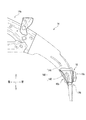
図2(a)に示されるように、各アッパメンバ14は、アッパメンバ上部14aと、アッパメンバ下部(車両前方側の先端部)14bとから構成されている。アッパメンバ上部14aは、図示しないフロントピラーから車両前方に向けて下り勾配で延出している。アッパメンバ下部14bは、アッパメンバ上部14aから車両下方に向けて下り勾配で上下方向に沿って延出している。
As shown in FIG. 2A, each
アッパメンバ上部14aよりも車両前方側に位置するアッパメンバ下部14bは、車幅方向の外側に向けて傾斜している。すなわち、図3に示されるように、アッパメンバ下部14bの車幅方向に沿った外縁104及び内縁106の両方は、それぞれ、その先端にいくほど鉛直線Vで示される仮想の外縁及び仮想の内縁に対する離間距離(偏位量)が大きくなり、外側に向けて傾斜している。なお、アッパメンバ下部14bの外縁104及び内縁106の外側への傾斜量は、それぞれ同じであってもよいし、又は、それぞれ異なるように設定されてもよい。
The upper member
図2(a)に示されるように、各アッパメンバ14(アッパメンバ下部14b)は、車幅方向の内側に設けられた脆弱部112を有する。この脆弱部112は、切欠部114によって構成されている。
As shown in FIG. 2A, each upper member 14 (upper member
切欠部114は、アッパメンバ上部14aに接続されるアッパメンバ下部14bにおいて、アッパメンバインナ108の内側フランジ116の角部を、略L字状に切り欠いて形成されている(図2(b)参照)。アッパメンバインナ108の内側フランジ116を切り欠くことで、アッパメンバアウタ(アウタ部材)110の内側フランジ118が露出している。なお、本実施形態では、脆弱部112として、切欠部114を例示しているがこれに限定されるものではなく、他の構造で代替してもよい。
The
本実施形態では、脆弱部112である切欠部114を、アッパメンバ14の車幅方向の内側でダンパハウジング100に近接する部位に配置しているが、これに限定されるものではない。脆弱部112である切欠部114は、アッパメンバ14の車幅方向の内側で、且つ、連結部材16とダンパハウジング100との間の部位であれば、いずれに配置されてもよい。
In the present embodiment, the
各アッパメンバ14は、アッパメンバインナ108とアッパメンバアウタ110とが閉断面を有してフランジ同士が一体的に接合されている。図4に示されるように、車両後方に位置するアッパメンバ上部14aは、車両前方側の前側インナ部材108aと、車両後方側の後側インナ部材108bとを有する。なお、図4は、図5に示す前側インナ部材108aと後側インナ部材108bの連結部位からブラケット126を取り外した状態を示している。
In each
図4に示されるように、右アッパメンバ14において、前側インナ部材108aの車両後方の上端部には、略矩形状の外側切り欠き120が形成されている。後側インナ部材108bの車両前方の上端部には、略矩形状の外側切り欠き122が形成されている。前側インナ部材108aの外側切り欠き120と、後側インナ部材108bの外側切り欠き122とによって、略矩形状の隙間124が形成されている。なお、前側インナ部材108a及び後側インナ部材108bの外側に配置されたアウタ部材110は、連続して形成されている。
As shown in FIG. 4, in the right
この隙間124は、前側インナ部材108aと後側インナ部材108bとを互いに連結するブラケット126によって接合(被覆)されている。換言すると、前側インナ部材108aと後側インナ部材108bとの連結部位に隙間124が設けられている。
The
図5に示されるように、このブラケット126は、パッチ状のブラケット本体128と、ブラケット本体128の上部に設けられボルト取付孔130が形成された支持部132とを有する。このブラケット126は、ウォータータンク134(図2(a)参照)を保持するものであり、支持部132には、図示しないボルトを介してウォータータンク134が取り付けられる。
As shown in FIG. 5, the
アッパメンバアウタ110、前側インナ部材108a、及び、ブラケット126は、それぞれ、スポット溶接等によって三者が一体的に接合されている。また、アッパメンバアウタ110、後側インナ部材108b、及び、ブラケット126は、それぞれ、スポット溶接等によって三者が一体的に接合されている。
The upper member outer 110, the front
図6に示されるように、右アッパメンバ14のアッパメンバ下部14bの車幅方向の外側には、他の脆弱部140が設けられている。この他の脆弱部140は、所定間隔離間して配置された第1ビード142と第2ビード144とによって構成されている。第1ビード142は、車両前方に位置し側面視して略円弧状の凹部によって構成されている。第2ビード144は、第1ビード142よりも車両後方に位置し側面視して略円弧状の凹部によって構成されている。図7の透過側面図に示されるように、第1ビード142は、連結部材16の車幅方向の外側に位置している。また、第1ビード142は、上下方向に延在するアッパメンバ下部14bに沿って、上下方向に延在している。第1ビード142及び第2ビード144を、右アッパメンバ14のアッパメンバ下部14bの車幅方向の外側に設けることで、車幅方向(左右方向)の荷重に対して強く、車両前後方向の荷重に対して弱くなっている。さらに、アッパメンバ上部14aは、上下のメンバが分割構成された二股形状からなり、その内側がダンパハウジング100に接合されているため、車両前後方向の荷重を図示しないフロントピラー側に効率良く伝達させることができる。
As shown in FIG. 6, another weakened
図1に戻り、フロントバルクヘッド18は、車両前方端部に配置されている。このフロントバルクヘッド18は、左右一対のサイドステイ34、34と、アッパバルクメンバ36と、ロアバルクメンバ38とから構成されている。左右一対のサイドステイ34、34は、左右一対のフロントサイドフレーム12、12の前端部の近傍部位にそれぞれ鉛直上下方向に沿って略平行に配置されている。
Returning to FIG. 1, the
また、車両前方には、正面視して略矩形状の枠体146が配置されている。この枠体146は、上側に位置して車幅方向に沿って延在する連結部材16と、下側に位置して車幅方向に沿って延在するロアバルクメンバ38の車幅方向端部と、車幅方向の外側に位置して鉛直上下方向に沿って延在するアッパメンバ14と、車幅方向の内側に位置して鉛直上下方向に沿って延在するサイドステイ34とによって構成されている。枠体146で囲繞された内部には、空間部148が形成されている。この空間部148には、例えば、フォグランプ等のライト類や、センサ等が収納される。
A substantially
アッパバルクメンバ36は、左右一対のサイドステイ34、34の上端部の間に車幅方向に沿って架け渡されている。アッパバルクメンバ36は、軸直断面が略コ字状の開断面で構成されている。開断面の開口は、下を向いている。なお、開断面で形成された空間部内には、例えば、図示しないフードの開閉状態を検知するフード開閉センサと電気的に接続されるハーネスや、図示しないフードロックを取り付けるためのブラケット等が収納されている。
The
ロアバルクメンバ38は、左右一対のアッパメンバ下部14b、14bの下端部同士の間に車幅方向に沿って架け渡されている。ロアバルクメンバ38は、鉛直上下方向において、アッパバルクメンバ36の略下方に位置している。また、ロアバルクメンバ38は、サイドステイ34よりも車幅方向の両側にそれぞれ延出して、アッパメンバ下部14、14に結合されている。
The
図1に示されるように、左連結部材16は、左アッパメンバ14と左フロントサイドフレーム12との間に配置されている。右連結部材16は、右アッパメンバ14と右フロントサイドフレーム12との間に配置されている。各連結部材16は、左右一対のアッパメンバ14、14と、左右一対のフロントサイドフレーム12、12とを車幅方向に沿って相互に連結するものである。各連結部材16は、アッパメンバ14よりも剛性強度が高い部材で形成されている。
As shown in FIG. 1, the
図8(a)、図8(b)、図9(a)、図9(b)及び図10に示されるように、各連結部材16は、車両前方に位置する前側部材16aと、車両後方に位置する後側部材16bとによって構成されている。前側部材16aと後側部材16bとは、例えば、図示しない溶接手段等によって一体的に接合(結合)されている。前側部材16aの強度は、後側部材16bの強度よりも高くなっている。
As shown in FIG. 8A, FIG. 8B, FIG. 9A, FIG. 9B, and FIG. 10, each connecting
また、各連結部材16は、前側部材16aと後側部材16bとのそれぞれ上下面同士が、車両前後方向で固定されている。すなわち、前側部材16aの上部フランジ部24と後側部材16bの上部フランジ部30同士、及び、前側部材16aの下部フランジ部26と後側部材16bの下部フランジ部32同士をそれぞれ車両前後方向から接続した状態で、例えば、図示しない溶接手段等によって一体的に接合されている(図8参照)。なお、図8(a)、図8(b)において、「×」印は、前側部材16aと後側部材16bとの接合部位を示している。
Moreover, as for each
前側部材16aは、その長手方向と直交する断面がハット状に形成されている(図10参照)。また、図9(a)に示されるように、前側部材16aは、前面部20と、上面部21と、側方フランジ部22a、22bと、上部フランジ部24と、下部フランジ部26(図8参照)、下面部29(図10参照)とから構成されている。
The cross section orthogonal to the longitudinal direction of the
前面部20は、車両前方側から正面視して略矩形状に形成され、略鉛直面で車幅方向に沿って延在している。一方の側方フランジ部22aは、前面部20の車幅方向外側に位置してアッパメンバ14(アッパメンバ下部14b)に3点で連結(接合)されている。他方の側方フランジ部22bは、前面部20の車幅方向内側に位置しフロントサイドフレーム12に対して3点で連結(接合)されている。上面部21と下面部29とは、略鉛直上下方向で対向している。
The
図10に示されるように、上部フランジ部24は、上面部21の車両後方に右上がり勾配で折曲して形成されている。下部フランジ部26は、下面部29の車両後方に左下がり勾配で折曲して形成されている。上面部21には、車両前後方向に沿って延在する複数のスリット27が並設されている。
As shown in FIG. 10, the
図9(b)、図10に示されるように、後側部材16bは、前側部材16aの前面部20と対向する略矩形状の前面部28と、前面部28の上部に形成され、前側部材16aの上部フランジ部24と3点で接合される上部フランジ部30と、前側部材16aの下部フランジ部26と3点(図8(a)、図8(b)参照)で接合される下部フランジ部32とを有する。なお、図10に示されるように、前側部材16aの上面部21は、下面部29よりも車両後方に延出して長くなっている。これにより、前側部材16aの車両前方に臨む前面部20に対して、後側部材16bの車両後方に臨む前面部28が右上がりに傾斜した状態で結合されている。
As shown in FIGS. 9B and 10, the
本実施形態に係る車体前部構造が適用された車体前部10は、基本的に以上のように構成されるものであり、次にその作用効果について説明する。
The vehicle
本実施形態では、アッパメンバ14のアッパメンバ下部14b(外縁104、内縁106)を車幅方向の外側へ向けて傾斜させることで、矩形状の枠体146の空間部148内の収納スペースが増大する。これにより、例えば、センサ等の部品を枠体の空間部148内に追加収納することができる。
In this embodiment, the storage space in the
また、本実施形態では、アッパメンバ14の車幅方向の内側で、連結部材16とダンパハウジング100との間の部位に脆弱部112を設けている。これにより、本実施形態では、アッパメンバ14の先端部であるアッパメンバ下部14bが車幅方向の外側に傾斜している場合であっても、アッパメンバ14に対して入力された衝突荷重を脆弱部112で吸収してアッパメンバ14が外側に曲がることを抑制することができる。換言すると、アッパメンバ14に対して衝突荷重が入力された際、アッパメンバ14は、脆弱部112を有する車幅方向の内側に向かって変形し易くなり、アッパメンバ14の外側への変形が抑制される。
Further, in the present embodiment, the
本実施形態では、アッパメンバ14の車幅方向に沿った内側で、且つ、アッパメンバ14よりも剛性強度が高いダンパハウジング100と連結部材16との間に脆弱部112(切欠部114)を設けている。これにより、本実施形態では、剛性強度がダンパハウジング100や連結部材16よりも低い脆弱部112には、より一層大きな強度差を発生させることができる。この結果、本実施形態では、脆弱部112を介してアッパメンバ14が車幅方向の外側に曲がる(変形する)ことを抑制することができる。
In the present embodiment, a fragile portion 112 (notch portion 114) is provided between the
本実施形態では、アッパメンバ14の先端部であるアッパメンバ下部14bに他の脆弱部140からなる第1ビード142を設けている。これにより、本実施形態では、アッパメンバ14に対して衝突荷重が入力された際、第1ビード142を起点としてアッパメンバ14を車両後方に向かって早期に曲げることができる。また、第1ビード142をアッパメンバ14の車幅方向に沿った外側に設けることで、アッパメンバ14が車幅方向の外側に向かって変形することを抑制することができる。
In the present embodiment, a
本実施形態では、前側インナ部材108aと後側インナ部材108bとが隙間124を被覆するブラケット126で強固に連結(接合)されている。これにより、本実施形態では、アッパメンバ14に対してオフセット荷重が入力された際、アッパメンバアウタ110から前側インナ部材108a及び後側インナ部材108bが共に剥離することを抑制することができる。また、このブラケット126は、ウォータータンク保持用のブラケットと共用することができ、部品点数を削減することができる。
In the present embodiment, the front
本実施形態では、前側インナ部材108aの外側切り欠き120と後側インナ部材108bの外側切り欠き122とによって前側インナ部材108aと後側インナ部材108bとの間に隙間124を形成している。この隙間124により、本実施形態では、アッパメンバ14の大型化を防止することができる。また、隙間124を設けたことによる剛性強度の低下をブラケット126によって抑制することができる。さらに、本実施形態では、比較的剛性強度が高いダンパハウジング100の上方部位にブラケット126を配置することで、オフセット荷重が入力された際のブラケット126の損傷乃至変形を抑制することができる。
In the present embodiment, a
10 車体前部
12 フロントサイドフレーム
14 アッパメンバ
14b アッパメンバ下部(先端部)
16 連結部材
100 ダンパハウジング
108a 前側インナ部材
108b 後側インナ部材
110 アッパメンバアウタ(アウタ部材)
112 脆弱部
124 隙間
126 ブラケット
134 ウォータータンク
140 他の脆弱部
146 枠体
10 Car
16 connecting
112
Claims (5)
前記各フロントサイドフレームの車幅方向の外側にそれぞれ配置され、車両前後方向に沿って延びる左右一対のアッパメンバと、
を備え、
前記各アッパメンバは、車幅方向の外側に向けて傾斜する車両前方側の先端部と、車幅方向の内側に設けられた脆弱部とを有することを特徴とする車両前部構造。 A pair of left and right front side frames extending along the longitudinal direction of the vehicle;
A pair of left and right upper members that are respectively arranged on the outer sides of the front side frames in the vehicle width direction and extend along the vehicle longitudinal direction;
With
Each of the upper members includes a front end portion of the vehicle that is inclined toward the outer side in the vehicle width direction and a weak portion provided on the inner side in the vehicle width direction.
前記各フロントサイドフレームと前記各アッパメンバの前記先端部とを連結させる左右一対の連結部材と、
ダンパを固定するためのダンパハウジングと、
をさらに備え、
前記脆弱部は、前記ダンパハウジングと前記連結部材との間に設けられていることを特徴とする車両前部構造。 The vehicle front structure according to claim 1,
A pair of left and right connecting members that connect each front side frame and the tip of each upper member;
A damper housing for fixing the damper;
Further comprising
The vehicle front part structure, wherein the fragile part is provided between the damper housing and the connecting member.
前記各アッパメンバの前記先端部には、他の脆弱部が設けられ、
前記他の脆弱部は、前記連結部材の車幅方向の外側に位置していることを特徴とする車両前部構造。 The vehicle front structure according to claim 4,
In the tip portion of each upper member, another fragile portion is provided,
Said other weak part is located in the vehicle width direction outer side of the said connection member, The vehicle front part structure characterized by the above-mentioned.
前記各アッパメンバの上部には、アウタ部材に連結される前側インナ部材と後側インナ部材とを有し、
前記前側インナ部材と前記後側部材とは、ウォータータンクを保持するブラケットによって連結されていることを特徴とする車両前部構造。 The vehicle front structure according to any one of claims 1 to 3,
The upper part of each upper member has a front inner member and a rear inner member connected to the outer member,
The vehicle front structure, wherein the front inner member and the rear member are connected by a bracket that holds a water tank.
前記ブラケットは、前記ダンパハウジングの上方位置に配置され、
前記前側インナ部材及び前記後側部材に対して前記ブラケットが連結される連結部位には、前記前側インナ部材と前記後側部材との間で隙間が設けられていることを特徴とする車両前部構造。 The vehicle front structure according to claim 4,
The bracket is disposed at an upper position of the damper housing,
A vehicle front portion characterized in that a gap is provided between the front inner member and the rear member at a connecting portion where the bracket is connected to the front inner member and the rear member. Construction.
Priority Applications (2)
| Application Number | Priority Date | Filing Date | Title |
|---|---|---|---|
| JP2017105165A JP6535366B2 (en) | 2017-05-29 | 2017-05-29 | Front body structure |
| CN201810463710.6A CN108928395B (en) | 2017-05-29 | 2018-05-15 | Front body structure |
Applications Claiming Priority (1)
| Application Number | Priority Date | Filing Date | Title |
|---|---|---|---|
| JP2017105165A JP6535366B2 (en) | 2017-05-29 | 2017-05-29 | Front body structure |
Publications (2)
| Publication Number | Publication Date |
|---|---|
| JP2018199431A true JP2018199431A (en) | 2018-12-20 |
| JP6535366B2 JP6535366B2 (en) | 2019-06-26 |
Family
ID=64448735
Family Applications (1)
| Application Number | Title | Priority Date | Filing Date |
|---|---|---|---|
| JP2017105165A Expired - Fee Related JP6535366B2 (en) | 2017-05-29 | 2017-05-29 | Front body structure |
Country Status (2)
| Country | Link |
|---|---|
| JP (1) | JP6535366B2 (en) |
| CN (1) | CN108928395B (en) |
Cited By (4)
| Publication number | Priority date | Publication date | Assignee | Title |
|---|---|---|---|---|
| WO2020084864A1 (en) | 2018-10-23 | 2020-04-30 | パナソニックIpマネジメント株式会社 | Refrigerator |
| CN114590325A (en) * | 2020-12-04 | 2022-06-07 | 本田技研工业株式会社 | Vehicle body front structure and method of manufacturing the vehicle body front |
| JP2022089485A (en) * | 2020-12-04 | 2022-06-16 | 本田技研工業株式会社 | Body front structure |
| JP2022089471A (en) * | 2020-12-04 | 2022-06-16 | 本田技研工業株式会社 | Body front structure |
Families Citing this family (1)
| Publication number | Priority date | Publication date | Assignee | Title |
|---|---|---|---|---|
| JP7156991B2 (en) * | 2019-03-29 | 2022-10-19 | 本田技研工業株式会社 | Subframe structure |
Citations (3)
| Publication number | Priority date | Publication date | Assignee | Title |
|---|---|---|---|---|
| JP2007238028A (en) * | 2006-03-10 | 2007-09-20 | Toyota Motor Corp | Body front structure |
| JP2012148691A (en) * | 2011-01-20 | 2012-08-09 | Honda Motor Co Ltd | Vehicle body front structure of automobile |
| JP2015071328A (en) * | 2013-10-02 | 2015-04-16 | 日産自動車株式会社 | Vehicle body front part structure of vehicle |
Family Cites Families (2)
| Publication number | Priority date | Publication date | Assignee | Title |
|---|---|---|---|---|
| US8882184B2 (en) * | 2011-02-23 | 2014-11-11 | Honda Motor Co., Ltd. | Structure for front portion of automobile body |
| CN105980242B (en) * | 2014-02-12 | 2017-08-29 | 本田技研工业株式会社 | Car body fore part arrangement |
-
2017
- 2017-05-29 JP JP2017105165A patent/JP6535366B2/en not_active Expired - Fee Related
-
2018
- 2018-05-15 CN CN201810463710.6A patent/CN108928395B/en not_active Expired - Fee Related
Patent Citations (3)
| Publication number | Priority date | Publication date | Assignee | Title |
|---|---|---|---|---|
| JP2007238028A (en) * | 2006-03-10 | 2007-09-20 | Toyota Motor Corp | Body front structure |
| JP2012148691A (en) * | 2011-01-20 | 2012-08-09 | Honda Motor Co Ltd | Vehicle body front structure of automobile |
| JP2015071328A (en) * | 2013-10-02 | 2015-04-16 | 日産自動車株式会社 | Vehicle body front part structure of vehicle |
Cited By (6)
| Publication number | Priority date | Publication date | Assignee | Title |
|---|---|---|---|---|
| WO2020084864A1 (en) | 2018-10-23 | 2020-04-30 | パナソニックIpマネジメント株式会社 | Refrigerator |
| CN114590325A (en) * | 2020-12-04 | 2022-06-07 | 本田技研工业株式会社 | Vehicle body front structure and method of manufacturing the vehicle body front |
| JP2022089485A (en) * | 2020-12-04 | 2022-06-16 | 本田技研工業株式会社 | Body front structure |
| JP2022089471A (en) * | 2020-12-04 | 2022-06-16 | 本田技研工業株式会社 | Body front structure |
| JP7177815B2 (en) | 2020-12-04 | 2022-11-24 | 本田技研工業株式会社 | Body front structure |
| JP7177813B2 (en) | 2020-12-04 | 2022-11-24 | 本田技研工業株式会社 | Body front structure |
Also Published As
| Publication number | Publication date |
|---|---|
| CN108928395A (en) | 2018-12-04 |
| JP6535366B2 (en) | 2019-06-26 |
| CN108928395B (en) | 2020-12-04 |
Similar Documents
| Publication | Publication Date | Title |
|---|---|---|
| JP6284556B2 (en) | Body front structure | |
| JP4478654B2 (en) | Body floor structure | |
| JP6550641B2 (en) | Front body structure of the vehicle | |
| JP2007186040A (en) | Car body rear structure | |
| JP6535366B2 (en) | Front body structure | |
| US10717469B2 (en) | Vehicle body front part structure | |
| JP2015101218A (en) | Lower body structure | |
| CN105339242A (en) | Subframe for vehicle | |
| CN105730509B (en) | Vehicle body front structure | |
| JP6340021B2 (en) | Battery fixing structure | |
| JP6435582B2 (en) | Battery retention structure | |
| JP2020011616A (en) | Vehicle rear part structure | |
| JP2016060435A (en) | Body front structure | |
| JP6156356B2 (en) | Vehicle rear structure | |
| JPWO2016163224A1 (en) | Vehicle battery mounting structure | |
| US11161553B2 (en) | Vehicle body front structure | |
| JP2018149904A (en) | Front bumper cover support structure | |
| CN107031736A (en) | Vehicle body front structure | |
| JP6575917B2 (en) | Car body rear structure | |
| JP2017001621A (en) | Vehicle front structure | |
| JP6378301B2 (en) | Car body superstructure and method of assembling car body superstructure | |
| JP6094364B2 (en) | Body front structure | |
| JP2018199430A (en) | Body front structure | |
| JP2002205665A (en) | Wheelhouse structure | |
| WO2016120993A1 (en) | Power unit support structure |
Legal Events
| Date | Code | Title | Description |
|---|---|---|---|
| A977 | Report on retrieval |
Free format text: JAPANESE INTERMEDIATE CODE: A971007 Effective date: 20181012 |
|
| A131 | Notification of reasons for refusal |
Free format text: JAPANESE INTERMEDIATE CODE: A131 Effective date: 20181023 |
|
| A521 | Request for written amendment filed |
Free format text: JAPANESE INTERMEDIATE CODE: A523 Effective date: 20181225 |
|
| TRDD | Decision of grant or rejection written | ||
| A01 | Written decision to grant a patent or to grant a registration (utility model) |
Free format text: JAPANESE INTERMEDIATE CODE: A01 Effective date: 20190528 |
|
| A61 | First payment of annual fees (during grant procedure) |
Free format text: JAPANESE INTERMEDIATE CODE: A61 Effective date: 20190531 |
|
| R150 | Certificate of patent or registration of utility model |
Ref document number: 6535366 Country of ref document: JP Free format text: JAPANESE INTERMEDIATE CODE: R150 |
|
| LAPS | Cancellation because of no payment of annual fees |