JP2018199455A - tire - Google Patents
tire Download PDFInfo
- Publication number
- JP2018199455A JP2018199455A JP2017105841A JP2017105841A JP2018199455A JP 2018199455 A JP2018199455 A JP 2018199455A JP 2017105841 A JP2017105841 A JP 2017105841A JP 2017105841 A JP2017105841 A JP 2017105841A JP 2018199455 A JP2018199455 A JP 2018199455A
- Authority
- JP
- Japan
- Prior art keywords
- axial groove
- tire
- land
- land portion
- shaped
- Prior art date
- Legal status (The legal status is an assumption and is not a legal conclusion. Google has not performed a legal analysis and makes no representation as to the accuracy of the status listed.)
- Granted
Links
Images




Classifications
-
- B—PERFORMING OPERATIONS; TRANSPORTING
- B60—VEHICLES IN GENERAL
- B60C—VEHICLE TYRES; TYRE INFLATION; TYRE CHANGING; CONNECTING VALVES TO INFLATABLE ELASTIC BODIES IN GENERAL; DEVICES OR ARRANGEMENTS RELATED TO TYRES
- B60C11/00—Tyre tread bands; Tread patterns; Anti-skid inserts
- B60C11/03—Tread patterns
- B60C11/0327—Tread patterns characterised by special properties of the tread pattern
-
- B—PERFORMING OPERATIONS; TRANSPORTING
- B60—VEHICLES IN GENERAL
- B60C—VEHICLE TYRES; TYRE INFLATION; TYRE CHANGING; CONNECTING VALVES TO INFLATABLE ELASTIC BODIES IN GENERAL; DEVICES OR ARRANGEMENTS RELATED TO TYRES
- B60C11/00—Tyre tread bands; Tread patterns; Anti-skid inserts
- B60C11/03—Tread patterns
-
- B—PERFORMING OPERATIONS; TRANSPORTING
- B60—VEHICLES IN GENERAL
- B60C—VEHICLE TYRES; TYRE INFLATION; TYRE CHANGING; CONNECTING VALVES TO INFLATABLE ELASTIC BODIES IN GENERAL; DEVICES OR ARRANGEMENTS RELATED TO TYRES
- B60C11/00—Tyre tread bands; Tread patterns; Anti-skid inserts
- B60C11/03—Tread patterns
- B60C11/04—Tread patterns in which the raised area of the pattern consists only of continuous circumferential ribs, e.g. zig-zag
-
- B—PERFORMING OPERATIONS; TRANSPORTING
- B60—VEHICLES IN GENERAL
- B60C—VEHICLE TYRES; TYRE INFLATION; TYRE CHANGING; CONNECTING VALVES TO INFLATABLE ELASTIC BODIES IN GENERAL; DEVICES OR ARRANGEMENTS RELATED TO TYRES
- B60C11/00—Tyre tread bands; Tread patterns; Anti-skid inserts
- B60C11/01—Shape of the shoulders between tread and sidewall, e.g. rounded, stepped or cantilevered
-
- B—PERFORMING OPERATIONS; TRANSPORTING
- B60—VEHICLES IN GENERAL
- B60C—VEHICLE TYRES; TYRE INFLATION; TYRE CHANGING; CONNECTING VALVES TO INFLATABLE ELASTIC BODIES IN GENERAL; DEVICES OR ARRANGEMENTS RELATED TO TYRES
- B60C11/00—Tyre tread bands; Tread patterns; Anti-skid inserts
- B60C11/03—Tread patterns
- B60C11/0306—Patterns comprising block rows or discontinuous ribs
-
- B—PERFORMING OPERATIONS; TRANSPORTING
- B60—VEHICLES IN GENERAL
- B60C—VEHICLE TYRES; TYRE INFLATION; TYRE CHANGING; CONNECTING VALVES TO INFLATABLE ELASTIC BODIES IN GENERAL; DEVICES OR ARRANGEMENTS RELATED TO TYRES
- B60C11/00—Tyre tread bands; Tread patterns; Anti-skid inserts
- B60C11/03—Tread patterns
- B60C11/11—Tread patterns in which the raised area of the pattern consists only of isolated elements, e.g. blocks
-
- B—PERFORMING OPERATIONS; TRANSPORTING
- B60—VEHICLES IN GENERAL
- B60C—VEHICLE TYRES; TYRE INFLATION; TYRE CHANGING; CONNECTING VALVES TO INFLATABLE ELASTIC BODIES IN GENERAL; DEVICES OR ARRANGEMENTS RELATED TO TYRES
- B60C11/00—Tyre tread bands; Tread patterns; Anti-skid inserts
- B60C11/03—Tread patterns
- B60C11/12—Tread patterns characterised by the use of narrow slits or incisions, e.g. sipes
-
- B—PERFORMING OPERATIONS; TRANSPORTING
- B60—VEHICLES IN GENERAL
- B60C—VEHICLE TYRES; TYRE INFLATION; TYRE CHANGING; CONNECTING VALVES TO INFLATABLE ELASTIC BODIES IN GENERAL; DEVICES OR ARRANGEMENTS RELATED TO TYRES
- B60C11/00—Tyre tread bands; Tread patterns; Anti-skid inserts
- B60C11/03—Tread patterns
- B60C11/12—Tread patterns characterised by the use of narrow slits or incisions, e.g. sipes
- B60C11/1204—Tread patterns characterised by the use of narrow slits or incisions, e.g. sipes with special shape of the sipe
-
- B—PERFORMING OPERATIONS; TRANSPORTING
- B60—VEHICLES IN GENERAL
- B60C—VEHICLE TYRES; TYRE INFLATION; TYRE CHANGING; CONNECTING VALVES TO INFLATABLE ELASTIC BODIES IN GENERAL; DEVICES OR ARRANGEMENTS RELATED TO TYRES
- B60C11/00—Tyre tread bands; Tread patterns; Anti-skid inserts
- B60C11/03—Tread patterns
- B60C11/12—Tread patterns characterised by the use of narrow slits or incisions, e.g. sipes
- B60C11/1236—Tread patterns characterised by the use of narrow slits or incisions, e.g. sipes with special arrangements in the tread pattern
-
- B—PERFORMING OPERATIONS; TRANSPORTING
- B60—VEHICLES IN GENERAL
- B60C—VEHICLE TYRES; TYRE INFLATION; TYRE CHANGING; CONNECTING VALVES TO INFLATABLE ELASTIC BODIES IN GENERAL; DEVICES OR ARRANGEMENTS RELATED TO TYRES
- B60C11/00—Tyre tread bands; Tread patterns; Anti-skid inserts
- B60C11/03—Tread patterns
- B60C2011/0337—Tread patterns characterised by particular design features of the pattern
- B60C2011/0339—Grooves
- B60C2011/0341—Circumferential grooves
- B60C2011/0344—Circumferential grooves provided at the equatorial plane
-
- B—PERFORMING OPERATIONS; TRANSPORTING
- B60—VEHICLES IN GENERAL
- B60C—VEHICLE TYRES; TYRE INFLATION; TYRE CHANGING; CONNECTING VALVES TO INFLATABLE ELASTIC BODIES IN GENERAL; DEVICES OR ARRANGEMENTS RELATED TO TYRES
- B60C11/00—Tyre tread bands; Tread patterns; Anti-skid inserts
- B60C11/03—Tread patterns
- B60C2011/0337—Tread patterns characterised by particular design features of the pattern
- B60C2011/0339—Grooves
- B60C2011/0358—Lateral grooves, i.e. having an angle of 45 to 90 degees to the equatorial plane
- B60C2011/036—Narrow grooves, i.e. having a width of less than 3 mm
-
- B—PERFORMING OPERATIONS; TRANSPORTING
- B60—VEHICLES IN GENERAL
- B60C—VEHICLE TYRES; TYRE INFLATION; TYRE CHANGING; CONNECTING VALVES TO INFLATABLE ELASTIC BODIES IN GENERAL; DEVICES OR ARRANGEMENTS RELATED TO TYRES
- B60C11/00—Tyre tread bands; Tread patterns; Anti-skid inserts
- B60C11/03—Tread patterns
- B60C2011/0337—Tread patterns characterised by particular design features of the pattern
- B60C2011/0339—Grooves
- B60C2011/0358—Lateral grooves, i.e. having an angle of 45 to 90 degees to the equatorial plane
- B60C2011/0365—Lateral grooves, i.e. having an angle of 45 to 90 degees to the equatorial plane characterised by width
-
- B—PERFORMING OPERATIONS; TRANSPORTING
- B60—VEHICLES IN GENERAL
- B60C—VEHICLE TYRES; TYRE INFLATION; TYRE CHANGING; CONNECTING VALVES TO INFLATABLE ELASTIC BODIES IN GENERAL; DEVICES OR ARRANGEMENTS RELATED TO TYRES
- B60C11/00—Tyre tread bands; Tread patterns; Anti-skid inserts
- B60C11/03—Tread patterns
- B60C2011/0337—Tread patterns characterised by particular design features of the pattern
- B60C2011/0339—Grooves
- B60C2011/0358—Lateral grooves, i.e. having an angle of 45 to 90 degees to the equatorial plane
- B60C2011/0372—Lateral grooves, i.e. having an angle of 45 to 90 degees to the equatorial plane with particular inclination angles
Landscapes
- Engineering & Computer Science (AREA)
- Mechanical Engineering (AREA)
- Tires In General (AREA)
Abstract
【課題】 ノイズ性能を向上させることができる。【解決手段】 トレッド部2に、タイヤ周方向にのびる少なくとも1本の陸部4が形成されたタイヤ1である。陸部4には、平面視において、タイヤ周方向の一方に突出するように曲がる複数の軸方向溝状部7が形成されている。軸方向溝状部7は、第1軸方向溝状部7Aと、第1軸方向溝状部7Aとは曲がり具合が異なる第2軸方向溝状部7Bとを含む。【選択図】図1PROBLEM TO BE SOLVED: To improve noise performance. SOLUTION: The tire 1 is formed with at least one land portion 4 extending in the tire circumferential direction on a tread portion 2. The land portion 4 is formed with a plurality of axial groove-shaped portions 7 that bend so as to project in one direction in the tire circumferential direction in a plan view. The axial groove-shaped portion 7 includes a first axial groove-shaped portion 7A and a second axial groove-shaped portion 7B having a degree of bending different from that of the first axial groove-shaped portion 7A. [Selection diagram] Fig. 1
Description
本発明は、トレッド部にタイヤ周方向にのびる陸部が形成されたタイヤに関する。 The present invention relates to a tire in which a land portion extending in a tire circumferential direction is formed on a tread portion.
下記特許文献1は、トレッド部に、タイヤ周方向にのびるミドル陸部が形成された空気入りタイヤを提案している。このミドル陸部には、トレッド平面視において、前記陸部を円弧状に横切る複数のミドル横溝が設けられている。 Patent Document 1 below proposes a pneumatic tire in which a middle land portion extending in the tire circumferential direction is formed in a tread portion. The middle land portion is provided with a plurality of middle lateral grooves that cross the land portion in an arc shape in a plan view of the tread.
上記特許文献1の空気入りタイヤでは、各ミドル横溝が同一の円弧状に形成されている。このため、上記特許文献1の空気入りタイヤは、前記ミドル横溝に起因する走行時の特定周波数帯域のピッチ音が重畳しやすく、ひいては、ノイズ性能が低下するという問題があった。 In the pneumatic tire disclosed in Patent Document 1, each middle lateral groove is formed in the same arc shape. For this reason, the pneumatic tire disclosed in Patent Document 1 has a problem in that a pitch sound in a specific frequency band at the time of traveling caused by the middle lateral groove is easily superimposed, and as a result, noise performance is deteriorated.
本発明は、以上のような実状に鑑み案出されたもので、ノイズ性能を向上することができるタイヤを提供することを主たる目的としている。 The present invention has been devised in view of the above circumstances, and has as its main object to provide a tire capable of improving noise performance.
本発明は、トレッド部に、タイヤ周方向にのびる少なくとも1本の陸部が形成されたタイヤであって、前記陸部には、平面視において、タイヤ周方向の一方に突出するように曲がる複数の軸方向溝状部が形成されており、前記軸方向溝状部は、第1軸方向溝状部と、前記第1軸方向溝状部とは曲がり具合が異なる第2軸方向溝状部とを含むことを特徴とする。 The present invention is a tire in which at least one land portion extending in the tire circumferential direction is formed on the tread portion, and the plurality of the land portions are bent so as to protrude to one side in the tire circumferential direction in plan view. The axial groove portion is formed of a first axial groove portion and a second axial groove portion that is different in bending from the first axial groove portion. It is characterized by including.
本発明に係る前記タイヤにおいて、前記第1軸方向溝状部と前記第2軸方向溝状部とがタイヤ周方向で隣接していてもよい。 In the tire according to the present invention, the first axial groove-shaped portion and the second axial groove-shaped portion may be adjacent to each other in the tire circumferential direction.
本発明に係る前記タイヤにおいて、前記第1軸方向溝状部又は前記第2軸方向溝状部は、平面視において、円弧状に延びていてもよい。 In the tire according to the present invention, the first axial groove portion or the second axial groove portion may extend in an arc shape in plan view.
本発明に係る前記タイヤにおいて、前記第1軸方向溝状部又は前記第2軸方向溝状部は、平面視において、V字状に延びていてもよい。 In the tire according to the present invention, the first axial groove portion or the second axial groove portion may extend in a V shape in plan view.
本発明に係る前記タイヤにおいて、前記陸部は、複数の前記軸方向溝状部によって複数のブロック状部に区分されており、前記各ブロック状部の踏面は、互いの面積を比べたときに1.2倍以下とされていてもよい。 In the tire according to the present invention, the land portion is divided into a plurality of block-like portions by a plurality of the axial groove-like portions, and the treads of the respective block-like portions are compared with each other in area. It may be 1.2 times or less.
本発明に係る前記タイヤにおいて、前記陸部は、互いに隣接する第1陸部と第2陸部とを含み、前記第1陸部及び前記第2陸部には、それぞれ、前記軸方向溝状部の複数が形成されており、前記第1陸部に形成された前記軸方向溝状部は、前記第2陸部に形成された前記軸方向溝状部に対して、タイヤ周方向において異なる位置に形成されていてもよい。 In the tire according to the present invention, the land portion includes a first land portion and a second land portion that are adjacent to each other, and each of the first land portion and the second land portion includes the axial groove shape. A plurality of portions are formed, and the axial groove-shaped portion formed in the first land portion is different from the axial groove-shaped portion formed in the second land portion in the tire circumferential direction. It may be formed at a position.
本発明に係る前記タイヤにおいて、前記第1陸部に形成された前記軸方向溝状部は、前記第2陸部に形成された前記軸方向溝状部に対して、距離L1でタイヤ周方向において異なる位置に形成され、前記距離L1は、前記第1軸方向溝状部のタイヤ周方向のピッチの0.1倍以上であってもよい。 In the tire according to the present invention, the axial groove-shaped portion formed in the first land portion is a tire circumferential direction at a distance L1 with respect to the axial groove-shaped portion formed in the second land portion. The distance L1 may be 0.1 times or more of the pitch in the tire circumferential direction of the first axial groove-shaped portion.
本発明に係る前記タイヤにおいて、前記曲がり具合は、前記軸方向溝状部の全長の中間部と、前記軸方向溝状部の両端部からそれぞれ前記全長の25%の長さを前記中間部側に隔てた第1端部及び第2端部とを用いた3点円弧の曲線半径であり、前記第1軸方向溝状部の曲率半径R1は、前記第2軸方向溝状部の曲率半径R2よりも大きくてもよい。 In the tire according to the present invention, the degree of bending may be set such that an intermediate portion of the entire length of the axial groove-shaped portion and 25% of the total length from both ends of the axial groove-shaped portion are on the intermediate portion side. A radius of curvature of a three-point arc using a first end and a second end separated from each other, and a radius of curvature R1 of the first axial groove is the radius of curvature of the second axial groove It may be larger than R2.
本発明に係る前記タイヤにおいて、前記第1軸方向溝状部の前記曲率半径R1は、前記第2軸方向溝状部の前記曲率半径R2の1.1〜10倍であってもよい。 In the tire according to the present invention, the curvature radius R1 of the first axial groove-shaped portion may be 1.1 to 10 times the curvature radius R2 of the second axial groove-shaped portion.
本発明に係る前記タイヤにおいて、前記軸方向溝状部は、前記第1軸方向溝状部の前記曲がり具合と、前記第2軸方向溝状部の前記曲がり具合との差が大きいほど、その深さが小さくなってもよい。 In the tire according to the present invention, the larger the difference between the bending state of the first axial groove portion and the bending state of the second axial groove portion, the larger the axial groove portion is. The depth may be reduced.
本発明のタイヤは、タイヤ周方向にのびる少なくとも1本の前記陸部に、タイヤ周方向の一方に突出するように曲がる複数の軸方向溝状部が形成されている。前記軸方向溝状部は、第1軸方向溝状部と、前記第1軸方向溝状部とは曲がり具合が異なる第2軸方向溝状部とを含んでいる。従って、本発明のタイヤは、曲がり具合が互いに異なる第1軸方向溝状部及び第2軸方向溝状部が、それぞれ異なる周波数帯域のピッチ音を生成し、ひいては、ピッチ音の周波数帯域を広い範囲に分散させることができる。従って、本発明のタイヤは、ノイズ性能を向上させることができる。 In the tire of the present invention, a plurality of axial groove portions that are bent so as to protrude to one side in the tire circumferential direction are formed in at least one of the land portions extending in the tire circumferential direction. The axial groove-shaped portion includes a first axial groove-shaped portion and a second axial groove-shaped portion that is different in bending from the first axial groove-shaped portion. Therefore, in the tire according to the present invention, the first axial groove-shaped portion and the second axial groove-shaped portion, which are different from each other in bending, generate pitch sounds in different frequency bands, and thus wide the frequency band of the pitch sounds. Can be dispersed in a range. Therefore, the tire of the present invention can improve noise performance.
以下、本発明の実施の一形態が図面に基づき説明される。
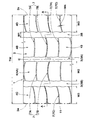
図1は、本発明のタイヤ1のトレッド部2の一例を示す展開図である。図2は、図1のA−A断面図である。本実施形態のタイヤ1は、例えば、トラックやバス等の重荷重用のものとして好適に使用される。
Hereinafter, an embodiment of the present invention will be described with reference to the drawings.
FIG. 1 is a development view showing an example of a
トレッド部2には、タイヤ周方向に連続してのびる複数の主溝3が設けられている。これらの主溝3により、トレッド部2には、タイヤ周方向にのびる少なくとも1本の陸部4、本実施形態では複数本の陸部4が形成されている。
The
本実施形態の主溝3は、センター主溝3Aと、ショルダー主溝3Bとを含んでいる。
The
本実施形態のセンター主溝3Aは、タイヤ赤道C上を、タイヤ周方向に沿ってのびている。なお、センター主溝3Aは、例えば、タイヤ赤道Cの両側に1本ずつ設けられるものでもよい。また、センター主溝3Aは、例えば、タイヤ周方向に、直線状、波状、又は、ジグザグ状にのびるものでもよい。
The center
ショルダー主溝3Bは、センター主溝3Aとトレッド接地端2eとの間で、タイヤ周方向に沿って連続してのびている。なお、ショルダー主溝3Bは、センター主溝3Aと同様に、例えば、タイヤ周方向に、直線状、波状、又は、ジグザグ状にのびるものでもよい。
The shoulder
「トレッド接地端2e」は、外観上、明瞭なエッジによって識別しうるときには当該エッジとする。なお、エッジが識別不能の場合には、正規リム(図示せず)にリム組みされかつ正規内圧が充填され、しかも正規荷重を負荷してキャンバー角0°でトレッド部2を平面に接地させたときの最もタイヤ軸方向外側の接地位置である。本明細書において、タイヤ1の各部の寸法は、特に断りがない限り、正規リムにリム組みされ、かつ、正規内圧が充填された無負荷の状態である正規状態において特定される値とする。
The “
「正規リム」は、タイヤ1が基づいている規格を含む規格体系において、当該規格がタイヤ毎に定めているリムであり、例えばJATMAであれば "標準リム" 、TRAであれば "Design Rim" 、ETRTOであれば "Measuring Rim" である。 The “regular rim” is a rim defined for each tire in the standard system including the standard on which the tire 1 is based. For example, “Standard Rim” for JATMA, “Design Rim” for TRA. For ETRTO, "Measuring Rim".
「正規内圧」は、タイヤ1が基づいている規格を含む規格体系において、各規格がタイヤ毎に定めている空気圧であり、JATMAであれば "最高空気圧" 、TRAであれば表 "TIRE LOAD LIMITS AT VARIOUS COLD INFLATION PRESSURES" に記載の最大値、ETRTOであれば "INFLATION PRESSURE" である。 “Regular internal pressure” is the air pressure that each standard defines for each tire in the standard system including the standard on which the tire 1 is based. “Maximum air pressure” for JATMA, “TIRE LOAD LIMITS” for TRA The maximum value described in “AT VARIOUS COLD INFLATION PRESSURES”, “INFLATION PRESSURE” in the case of ETRTO.
「正規荷重」は、タイヤ1が基づいている規格を含む規格体系において、各規格がタイヤ毎に定めている荷重であり、JATMAであれば "最大負荷能力" 、TRAであれば表 "TIRE LOAD LIMITS AT VARIOUS COLD INFLATION PRESSURES" に記載の最大値、ETRTOであれば "LOAD CAPACITY" である。 “Regular load” is a load determined by each standard for each tire in the standard system including the standard on which the tire 1 is based. “Maximum load capacity” for JATMA, “TIRE LOAD” for TRA The maximum value described in “LIMITS AT VARIOUS COLD INFLATION PRESSURES”, “LOAD CAPACITY” in the case of ETRTO.
センター主溝3A及びショルダー主溝3Bのタイヤ軸方向の幅W1、及び、深さD(図2に示す)については、適宜設定することができる。センター主溝3A及びショルダー主溝3Bの幅W1は、例えば、トレッド幅TWの4.0〜7.0%程度が望ましい。トレッド幅TWは、トレッド接地端2e、2e間のタイヤ軸方向距離である。センター主溝3A及びショルダー主溝3Bの深さDは、タイヤ1が重荷重用の場合、10〜25mm程度が望ましい。
The width W1 in the tire axial direction and the depth D (shown in FIG. 2) of the center
陸部4は、互いに隣接する第1陸部4Aと第2陸部4Bとを含んでいる。さらに、本実施形態の陸部4は、第3陸部4Cと第4陸部4Dとを含んでいる。これらの陸部4A〜4Dには、平面視において、タイヤ周方向の一方に突出するように曲がる複数の軸方向溝状部7が、それぞれ形成されている。これにより、各陸部4A〜4Dは、複数の軸方向溝状部7によって、複数のブロック状部10に区分されている。
The
本実施形態の第1陸部4A及び第2陸部4Bは、センター主溝3Aとショルダー主溝3B、3Bとの間にそれぞれ区分されている。第1陸部4Aは、センター主溝3Aに対して、タイヤ軸方向の一方側に配されている。第2陸部4Bは、センター主溝3Aに対して、タイヤ軸方向の他方側に配されている。従って、第1陸部4A及び第2陸部4Bは、センター主溝3Aを介して互いに隣接している。第1陸部4A及び第2陸部4Bの幅W2については、適宜設定することができる。本実施形態の幅W2は、トレッド幅TWの20%〜24%程度が望ましい。
The
第3陸部4C及び第4陸部4Dは、ショルダー主溝3B、3Bとトレッド接地端2eとの間にそれぞれ区分されている。第3陸部4Cは、ショルダー主溝3Bを介して、第1陸部4Aに隣接している。第4陸部4Dは、ショルダー主溝3Bを介して、第2陸部4Bに隣接している。第3陸部4C及び第4陸部4Dの幅W3については、適宜設定することができる。本実施形態の幅W3は、トレッド幅TWの18%〜22%程度が望ましい。
The
本実施形態の軸方向溝状部7は、その幅W4が1.5m未満のサイプとして構成されている。このような軸方向溝状部7は、タイヤ軸方向のエッジを提供し、トラクション性能及びウエット性能を向上することができる。
The
サイプとして構成された軸方向溝状部7により、陸部4は、タイヤ周方向に実質的に連続するリブとして形成される。ここで、リブについて「連続する」とは、幅が1.5mm以上の切り込みである横溝(図示省略)等によってタイヤ周方向に分断されていないことを意味する。このような陸部4は、例えば、横溝等で分断されたブロック列に比べて、タイヤ周方向及びタイヤ軸方向の剛性を高めることができる。従って、タイヤ1は、ドライ路面での走行性能を高めることができる。
The
また、軸方向溝状部7は、その幅W4が1.5mm以上の部分を含む横溝として構成されてもよい。このような軸方向溝状部7は、エッジを提供しつつ、路面の水膜を効果的に排水することができる。
Further, the
本実施形態の軸方向溝状部7は、その両端が、主溝3又はトレッド接地端2eに連通しているが、このような態様に限定されない。例えば、軸方向溝状部7の一端又は両端が、主溝3又はトレッド接地端2eに連通することなく、陸部4内で終端するものでもよい。このような軸方向溝状部7は、陸部4の剛性を効果的に高めることができる。
Both ends of the axial groove-shaped
本実施形態の軸方向溝状部7は、平面視において、円弧状に延びている。このような軸方向溝状部7は、タイヤ軸方向及びタイヤ周方向のエッジを提供できるため、トラクション性能を効果的に向上させることができる。さらに、軸方向溝状部7は、その縁部に作用する応力を分散させ、縁部を起点とした陸部4の偏摩耗を抑制することができる。
The
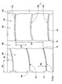
図3は、図1の第1陸部4A及び第2陸部4Bの拡大図である。本実施形態の軸方向溝状部7は、平面視において、その全長に亘って円弧状に形成されている。なお、軸方向溝状部7は、その全長に亘って円弧状に形成されるものに限定されない。例えば、軸方向溝状部7は、その全長の一部が、直線状や波状に形成されてもよい。なお、軸方向溝状部7の全長は、軸方向溝状部7の溝中心線7cと主溝3(センター主溝3A又はショルダー主溝3B)とが交わる軸方向溝状部7の両端部7t、7t間の距離として定義される。
FIG. 3 is an enlarged view of the
図1に示されるように、第1陸部4Aの軸方向溝状部7の突出方向と、第2陸部4Bの軸方向溝状部7の突出方向とは、タイヤ周方向において、逆向きに設定されるのが望ましい。また、第1陸部4Aの軸方向溝状部7の突出方向と、第3陸部4Cの軸方向溝状部7の突出方向とは、タイヤ周方向において、逆向きに設定されるのが望ましい。さらに、第2陸部4Bの軸方向溝状部7の突出方向と、第4陸部4Dの軸方向溝状部7の突出方向とは、タイヤ周方向において、逆向きに設定されるのが望ましい。これにより、第1陸部4A〜第4陸部4Dの各軸方向溝状部7は、タイヤの回転方向に関わらず、エッジを提供することができるため、トラクション性能及びウエット性能を向上させることができる。
As shown in FIG. 1, the protruding direction of the
本実施形態の軸方向溝状部7は、第1軸方向溝状部7Aと、第1軸方向溝状部7Aとは曲がり具合が異なる第2軸方向溝状部7Bとを含んでいる。第1軸方向溝状部7A及び第2軸方向溝状部7Bは、第1陸部4A及び第2陸部4Bに、それぞれ設けられている。本実施形態の第1軸方向溝状部7A及び第2軸方向溝状部7Bは、第1陸部4A及び第2陸部4Bのそれぞれにおいて、タイヤ周方向に交互に設けられている。
The
本明細書において、「曲がり具合」は、図3に示されるように、軸方向溝状部7の全長の中間部8aと、軸方向溝状部7の両端部7t、7tからそれぞれ全長の25%の長さL6を中間部8a側に隔てた第1端部8b及び第2端部8cとを用いた3点円弧の曲線半径として定義される。なお、中間部8a、第1端部8b及び第2端部8cは、軸方向溝状部7の溝中心線7c上で特定されるものとする。
In this specification, as shown in FIG. 3, the “bending degree” is the total length 25 from the
本実施形態において、第1軸方向溝状部7Aの曲率半径R1は、第2軸方向溝状部7Bの曲率半径R2よりも大きい。このような第1軸方向溝状部7A及び第2軸方向溝状部7Bは、それぞれ異なるエッジを提供することができるため、トラクション性能及びウエット性能を効果的に向上させることができる。なお、第1軸方向溝状部7Aの曲率半径R1は、第2軸方向溝状部7Bの曲率半径R2は、中間部8a、第1端部8b及び第2端部8cを用いた3点円弧の曲線半径として定義される。
In the present embodiment, the radius of curvature R1 of the first
第1軸方向溝状部7A及び第2軸方向溝状部7Bは、曲がり具合が互いに異なるため、それぞれ異なる周波数帯域のピッチ音を生成することができる。従って、タイヤ1は、ピッチ音の周波数帯域を広い範囲に分散させることができるため、ノイズ性能を向上させることができる。
Since the first
上記作用を効果的に発揮させるために、第1軸方向溝状部7A及び第2軸方向溝状部7Bは、タイヤ周方向で隣接するのが望ましい。これにより、それぞれ異なる周波数帯域のピッチ音が交互に生成されるため、ピッチ音の重畳を効果的に防ぐことができる。
In order to effectively exhibit the above action, it is desirable that the first
さらに、第1軸方向溝状部7Aの曲率半径R1は、第2軸方向溝状部7Bの曲率半径R2の1.1〜10倍が望ましい。なお、第1軸方向溝状部7Aの曲率半径R1は、第2軸方向溝状部7Bの曲率半径R2の1.1倍未満であると、ピッチ音の周波数帯域を広い範囲に分散させることができず、ノイズ性能を十分に向上できないおそれがある。逆に、第1軸方向溝状部7Aの曲率半径R1は、第2軸方向溝状部7Bの曲率半径R2の10倍を超えると、第1軸方向溝状部7A又は第2軸方向溝状部7Bを介してタイヤ周方向で隣り合うブロック状部10、10の剛性が不均一となり、偏摩耗が生じるおそれがある。このような観点より、第1軸方向溝状部7Aの曲率半径R1は、好ましくは、第2軸方向溝状部7Bの曲率半径R2の2倍以上であり、また、好ましくは、8倍以下である。
Furthermore, the curvature radius R1 of the first
第1軸方向溝状部7Aの曲率半径R1及び第2軸方向溝状部7Bの曲率半径R2については、第1軸方向溝状部7Aの曲率半径R1が第2軸方向溝状部7Bの曲率半径R2よりも大きければ、適宜設定することができる。なお、第1軸方向溝状部7Aの曲率半径R1及び第2軸方向溝状部7Bの曲率半径R2が小さいと、第1軸方向溝状部7A及び第2軸方向溝状部7Bを起点とした偏摩耗が発生しやすくなる。逆に、第1軸方向溝状部7Aの曲率半径R1及び第2軸方向溝状部7Bの曲率半径R2が大きいと、ウエット性能が低下するおそれがある。このような観点より、第1軸方向溝状部7Aの曲率半径R1は、60〜200mmが望ましく、また、第2軸方向溝状部7Bの曲率半径R2は、20〜100mmが望ましい。
Regarding the curvature radius R1 of the first
第1軸方向溝状部7A又は第2軸方向溝状部7Bを介してタイヤ周方向で隣り合うブロック状部10、10は、第1軸方向溝状部7Aの曲がり具合(曲率半径R1)と、第2軸方向溝状部7Bの曲がり具合(曲率半径R2)との差が大きくなるほど、それらの剛性差が大きくなり、偏摩耗が発生しやすい。このため、第1軸方向溝状部7Aの曲がり具合と、第2軸方向溝状部7Bの曲がり具合との差が大きいほど、軸方向溝状部7の深さ(図示省略)を小さくするのが望ましい。これにより、ブロック状部10、10の剛性差を小さくできるため、偏摩耗の発生を防ぐことができる。
The block-
上記作用を効果的に発揮させるために、軸方向溝状部7の深さDs(図2に示す)と主溝3の深さD(図2に示す)との比(Ds/D)は、下記式(1)を満足するのが望ましい。これにより、第1軸方向溝状部7Aの曲がり具合と、第2軸方向溝状部7Bの曲がり具合との差が大きいほど、主溝3の深さDに対して、軸方向溝状部7の深さDsの深さ(図示省略)を小さくすることができる。これにより、ブロック状部10、10の剛性差を小さくすることができる。
Ds/D<(R2+R1×2)/(R1×3)…(1)
In order to effectively exhibit the above action, the ratio (Ds / D) between the depth Ds of the axial groove 7 (shown in FIG. 2) and the depth D of the main groove 3 (shown in FIG. 2) is It is desirable that the following formula (1) is satisfied. Accordingly, the axial groove-shaped portion with respect to the depth D of the
Ds / D <(R2 + R1 × 2) / (R1 × 3) (1)
また、第1陸部4Aに形成された軸方向溝状部7は、第2陸部4Bに形成された軸方向溝状部7に対して、タイヤ周方向において異なる位置に形成されているのが望ましい。これにより、タイヤ1は、第1陸部4Aと第2陸部4Bとで、ピッチ音を発生させるタイミングをずらせるため、ピッチ音の重畳を効果的に防ぐことができる。
The
本実施形態の第1陸部4Aに形成された軸方向溝状部7は、第2陸部4Bに形成された軸方向溝状部7に対して、距離L1でタイヤ周方向において異なる位置に形成されている。本実施形態において、距離L1は、第1陸部4Aの第1軸方向溝状部7Aの端部7tと、第2陸部4Bの第1軸方向溝状部7Aの端部7tとに基づいて定義されている。また、距離L1は、第1陸部4Aの第1軸方向溝状部7Aの突出方向と、第2陸部4Bの第1軸方向溝状部7Aの突出方向とが離れる向きの距離として定義される。
The
なお、距離L1が、第1軸方向溝状部7Aのタイヤ周方向のピッチPに対して小さいと、ピッチ音を発生させるタイミングを十分にずらせない。逆に、距離L1が、ピッチPに対して大きいと、タイヤ周方向で隣接する他の軸方向溝状部7に対する距離L1が小さくなるおそれがある。このような観点より、距離L1は、好ましくは、ピッチPの0.1倍以上であり、また、好ましくは、ピッチPの0.9倍以下である。なお、第1軸方向溝状部7Aのタイヤ周方向のピッチPは、軸方向溝状部7の端部7tに基づいて定義される。なお、第1陸部4Aの第2軸方向溝状部7Bと、第2陸部4Bの第2軸方向溝状部7Bとの間の距離も、同一範囲に設定されるのが望ましい。
In addition, if the distance L1 is small with respect to the pitch P in the tire circumferential direction of the first
図1に示されるように、本実施形態の軸方向溝状部7は、第1軸方向溝状部7A及び第2軸方向溝状部7Bとは曲がり具合が異なる第3軸方向溝状部7Cを含んでいる。本実施形態の第3軸方向溝状部7Cは、第3陸部4C及び第4陸部4Dにそれぞれ設けられており、タイヤ周方向に隔設されている。このような第3軸方向溝状部7Cは、第1軸方向溝状部7A及び第2軸方向溝状部7Bとは異なるエッジを提供できるため、トラクション性能及びウエット性能を効果的に向上させることができる。
As shown in FIG. 1, the
図4は、図1の第1陸部4A及び第3陸部4Cの拡大図である。図5は、図1の第2陸部4B及び第4陸部4Dの拡大図である。本実施形態の第3軸方向溝状部7Cは、第3陸部4C及び第4陸部4Dの外側領域To内に中心を有する円弧に形成されている。
FIG. 4 is an enlarged view of the
「外側領域To」とは、第3陸部4C及び第4陸部4Dにおいて、幅方向の中心位置4cよりもタイヤ軸方向外側の領域である。このような第3軸方向溝状部7Cは、第3陸部4C及び第4陸部4Dの外側領域Toで相対的に接地圧が大きくなる旋回時において、エッジを効果的に提供できるため、旋回性能及びウエット性能を向上させることができる。
The “outer region To” is a region on the outer side in the tire axial direction than the
第3軸方向溝状部7Cの曲率半径R3については、適宜設定することができる。第3軸方向溝状部7Cの曲率半径R3は、図3に示した第1軸方向溝状部7Aの曲率半径R1及び第2軸方向溝状部7Bの曲率半径R2と同一の観点より、40〜200mmが望ましい。
The curvature radius R3 of the third
第3軸方向溝状部7Cのタイヤ軸方向の外端は、トレッド接地端2eに設けられるラグ溝11に連通している。これにより、第3軸方向溝状部7Cは、路面の水膜を、ラグ溝11から効果的に排水することができるため、ウエット性能を向上させることができる。
The outer end of the third
図4に示されるように、第3陸部4Cの第3軸方向溝状部7Cは、第1陸部4Aの軸方向溝状部7(本実施形態では、第1軸方向溝状部7A)に対して、距離L3でタイヤ周方向において異なる位置に形成されているのが望ましい。距離L3は、第3陸部4Cの第3軸方向溝状部7Cの端部7tと、第1陸部4Aの第1軸方向溝状部7Aの端部7tとに基づいて、定義される。また、距離L3は、第3陸部4Cの第3軸方向溝状部7Cの突出方向と、第1陸部4Aの第1軸方向溝状部7Aの突出方向とが離れる向きの距離として定義される。また、第3陸部4Cの第3軸方向溝状部7Cは、タイヤ周方向で隣り合う一対の第1軸方向溝状部7A、7Aに、2つ形成されている。このため、距離L3は、大小2つ定義される。これにより、タイヤ1は、第3陸部4Cと第1陸部4Aとで、ピッチ音を発生させるタイミングをずらせるため、ピッチ音の重畳を効果的に防ぐことができる。このような作用を効果的に発揮させるために、2つの距離L3のうち、小さい方の距離L3は、第1軸方向溝状部7Aのタイヤ周方向のピッチPの0.1〜0.4倍が望ましく、また、大きい方の距離L3は、ピッチPの0.6〜0.9倍が望ましい。
As shown in FIG. 4, the third
図5に示されるように、第4陸部4Dの第3軸方向溝状部7Cは、図4に示した第3陸部4Cの第3軸方向溝状部7C(図4に示す)と同様に、第2陸部4Bの軸方向溝状部7(本実施形態では、第1軸方向溝状部7A)に対して、距離L4でタイヤ周方向において異なる位置に形成されているのが望ましい。距離L4は、第4陸部4Dの第3軸方向溝状部7Cの端部7tと、第2陸部4Aの第1軸方向溝状部7Aの端部7tとに基づいて、定義される。また、距離L4は、距離L3(図4に示す)と同様に、大小2つ定義され、小さい方の距離L4は、第1軸方向溝状部7Aのタイヤ周方向のピッチPの0.1〜0.4倍が望ましく、また、大きい方の距離L4は、ピッチPの0.6〜0.9倍が望ましい。
As shown in FIG. 5, the third
図1に示されるように、本実施形態の第1軸方向溝状部7A及び第2軸方向溝状部7Bは、円弧状に延びている態様が例示されたが、このような態様に限定されない。図6は、本発明の他の実施形態のタイヤ1のトレッド部2の展開図である。この実施形態において、前実施形態と同一の構成については、同一の符号を付し、説明を省略することがある。
As shown in FIG. 1, the first
図6に示されるように、第1軸方向溝状部7A及び第2軸方向溝状部7Bは、平面視において、V字状に延びているものでもよい。なお、V字状の軸方向溝状部7の曲がり具合は、円弧状の軸方向溝状部7の曲がり具合と同様に、図3に示した第1端部8b及び第2端部8cとを用いた3点円弧の曲線半径として定義される。
As shown in FIG. 6, the first
このようなV字状の軸方向溝状部7は、円弧状の軸方向溝状部7に比べて、ナイフブレードによる加工が容易であり、また、デザインのバリエーションを容易に広げることができる。また、第3軸方向溝状部7Cも、V字状に延びていても良い。
Such a V-shaped
図7(a)、(b)は、本発明のさらに他の実施形態のタイヤのトレッド部の部分展開図である。この実施形態において、前実施形態と同一の構成については、同一の符号を付し、説明を省略することがある。 7A and 7B are partial development views of a tread portion of a tire according to still another embodiment of the present invention. In this embodiment, the same components as those of the previous embodiment are denoted by the same reference numerals and description thereof may be omitted.
図7(a)の実施形態では、平面視において、第1軸方向溝状部7Aが円弧状に延びるとともに、第2軸方向溝状部7BがV字状の延びていても良い。さらに、図7(b)の実施形態では、平面視において、第1軸方向溝状部7AがV字状に延びるとともに、第2軸方向溝状部7Bが円弧状の延びていても良い。このように、これらの実施形態では、円弧状に延びる第1軸方向溝状部7A又は第2軸方向溝状部7Bと、V字状に延びる第1軸方向溝状部7A又は第2軸方向溝状部7Bとを混在させることができるため、ピッチ音の重畳をより効果的に防ぎつつ、トラクション性能及びウエット性能を向上させることができる。
In the embodiment of FIG. 7A, the first
図1に示されるように、各ブロック状部10は、平面視において、横長矩形状に形成されている。このようなブロック状部10は、タイヤ軸方向の剛性を高めることができるため、操縦安定性能を向上しうる。図3に示されるように、ブロック状部10の主溝3側のブロック縁10eは、平面視において、ジグザグ状に形成されている。このようなブロック縁10eは、エッジを効果的に提供できるため、トラクション性能、及び、旋回性能を向上させることができる。
As shown in FIG. 1, each block-shaped
各ブロック状部10の踏面10sは、互いの面積を比べたときに1.2倍以下とされるのが望ましい。これにより、ブロック状部10、10の剛性を均一に近づけることができるため、偏摩耗を抑制することができる。このような観点より、各ブロック状部10の踏面10sは、好ましくは、互いの面積を比べたとき1.1倍以下であり、より好ましくは、1.05倍以下であり、さらに好ましくは、1.0倍である。
It is desirable that the
以上、本発明の特に好ましい実施形態について詳述したが、本発明は図示の実施形態に限定されることなく、種々の態様に変形して実施しうる。 As mentioned above, although especially preferable embodiment of this invention was explained in full detail, this invention is not limited to embodiment of illustration, It can deform | transform and implement in a various aspect.
図1に示す基本構造を有し、かつ、表1の軸方向溝状部を有するタイヤが試作された(実施例1〜9、比較例)。実施例1〜9の軸方向溝状部には、第1軸方向溝状部と、第1軸方向溝状部とは曲がり具合(曲率半径)が異なる第2軸方向溝状部が含まれている。他方、比較例の軸方向溝状部は、曲がり具合が同一の第1軸方向溝状部及び第2軸方向溝状部が含まれている。そして、実施例1〜9のタイヤ、及び、比較例のタイヤについて、それらの性能が評価された。各実施例及び比較例に共通する仕様は、以下のとおりである。
サイズ:275/70R22.5
リム:22.5×8.25
タイヤ内圧:900kPa
テスト車両:CITYBUS(巡回バス)
テストタイヤの装着位置:全輪
トレッド幅TW:242mm
主溝:
幅W1/TW:5.5%〜6.8%
深さD:20.0mm
第1陸部及び第2陸部のW2/TW:21.9%
第3陸部及び第4陸部の幅W3/TW:19.2%
第1軸方向溝状部のタイヤ周方向のピッチP:60.7mm
第1陸部の軸方向溝状部と、第2陸部の軸方向溝状部との間の距離L1/ピッチP:0.32
第3陸部の第3軸方向溝状部と、第1陸部の第1軸方向溝状部との間の距離L3/ピッチP:0.32、0.82
第4陸部の第3軸方向溝状部と、第2陸部の第1軸方向溝状部との間の距離L4/ピッチP:0.32、0.82
第3軸方向溝状部の曲がり具合(曲率半径)R3:80mm
テスト方法は、次のとおりである
Tires having the basic structure shown in FIG. 1 and having the axial groove portions of Table 1 were manufactured (Examples 1 to 9, Comparative Examples). The axial groove portions of Examples 1 to 9 include a first axial groove portion and a second axial groove portion having a different bending degree (curvature radius) from the first axial groove portion. ing. On the other hand, the axial groove portion of the comparative example includes a first axial groove portion and a second axial groove portion having the same bending condition. And the performance was evaluated about the tire of Examples 1-9 and the tire of a comparative example. The specifications common to each example and comparative example are as follows.
Size: 275 / 70R22.5
Rims: 22.5 × 8.25
Tire internal pressure: 900kPa
Test vehicle: CITYBUS (tour bus)
Test tire mounting position: All wheels Tread width TW: 242mm
Main groove:
Width W1 / TW: 5.5% to 6.8%
Depth D: 20.0mm
W2 / TW of the 1st land part and the 2nd land part: 21.9%
Width W3 / TW of the third land part and the fourth land part: 19.2%
Pitch P in the tire circumferential direction of the first axial groove portion: 60.7 mm
Distance L1 / pitch P: 0.32 between the axial groove portion of the first land portion and the axial groove portion of the second land portion
Distance L3 / pitch P between the third axial groove portion of the third land portion and the first axial groove portion of the first land portion: 0.32, 0.82
Distance L4 / pitch P: 0.32, 0.82 between the third axial groove portion of the fourth land portion and the first axial groove portion of the second land portion
Bending degree of the third axial groove (curvature radius) R3: 80 mm
The test method is as follows
<耐偏摩耗性能>
上記テスト車両で、乾燥した舗装路面を10000km走行した後に、第1陸部及び第2陸部において、複数箇所の摩耗量が測定され、これらの摩耗量のバラツキが求められた。結果は、実施例1の摩耗量のバラツキを100とする指数で表示されている。数値が小さいほど良好である。
<Uneven wear resistance>
After traveling 10,000 km on the dry paved road surface with the above test vehicle, the wear amounts at a plurality of locations were measured in the first land portion and the second land portion, and variations in these wear amounts were determined. The results are displayed as an index with the variation in wear amount of Example 1 as 100. The smaller the value, the better.
<ノイズ性能>
上記テスト車両で、乾燥した舗装路面を速度60km/hで走行させ、車室内で聴取されるノイズがドライバーの官能により評価された。結果は、実施例1を100とする指数で表示されている。数値が小さいほど良好である。
<Noise performance>
With the test vehicle, a dry paved road surface was run at a speed of 60 km / h, and the noise heard in the passenger compartment was evaluated by the driver's sensuality. The results are displayed as an index with Example 1 as 100. The smaller the value, the better.
<ウエット性能>
上記テスト車両で、厚さ2mmの水膜を有するアスファルト路面に65km/hの速度で進入し、急制動が行われた。このとき、テスト車両が60km/hから20km/hまで減速するのに要した時間が測定された。結果は、実施例1を100とする指数で表示されており、数値が小さいほど良好である。
テストの結果を表1に示す。
<Wet performance>
In the above test vehicle, the vehicle entered an asphalt road surface having a water film with a thickness of 2 mm at a speed of 65 km / h, and sudden braking was performed. At this time, the time required for the test vehicle to decelerate from 60 km / h to 20 km / h was measured. The results are displayed as an index with Example 1 as 100, and the smaller the value, the better.
The test results are shown in Table 1.

テストの結果、実施例1〜9のタイヤは、比較例のタイヤに比べて、ノイズ性能を向上させることができた。さらに、実施例2及び実施例3は、各ブロック状部の踏面の面積比が1.0に設定され、かつ、軸方向溝状部の深さと主溝の深さとの比Ds/Dが、(R2+R1×2)/(R1×3)よりも小さく設定されたため、耐偏摩耗性能を維持しつつ、ノイズ性能を向上させることができた。 As a result of the test, the tires of Examples 1 to 9 were able to improve the noise performance as compared with the tire of the comparative example. Furthermore, in Example 2 and Example 3, the area ratio of the tread surface of each block-shaped part is set to 1.0, and the ratio Ds / D between the depth of the axial groove-shaped part and the depth of the main groove is Since it was set smaller than (R2 + R1 × 2) / (R1 × 3), it was possible to improve noise performance while maintaining uneven wear resistance.
1 タイヤ
2 トレッド部
4 陸部
7 軸方向溝状部
7A 第1軸方向溝状部
7B 第2軸方向溝状部
DESCRIPTION OF SYMBOLS 1
Claims (10)
前記陸部には、平面視において、タイヤ周方向の一方に突出するように曲がる複数の軸方向溝状部が形成されており、
前記軸方向溝状部は、第1軸方向溝状部と、前記第1軸方向溝状部とは曲がり具合が異なる第2軸方向溝状部とを含む、
タイヤ。 A tire in which at least one land portion extending in the tire circumferential direction is formed in the tread portion,
The land portion is formed with a plurality of axial groove-like portions that bend so as to protrude in one of the tire circumferential directions in plan view,
The axial groove-shaped portion includes a first axial groove-shaped portion and a second axial groove-shaped portion having a bending state different from that of the first axial groove-shaped portion.
tire.
前記第1陸部及び前記第2陸部には、それぞれ、前記軸方向溝状部の複数が形成されており、
前記第1陸部に形成された前記軸方向溝状部は、前記第2陸部に形成された前記軸方向溝状部に対して、タイヤ周方向において異なる位置に形成されている請求項1乃至5のいずれかに記載のタイヤ。 The land portion includes a first land portion and a second land portion adjacent to each other,
Each of the first land portion and the second land portion is formed with a plurality of the axial groove portions,
The axial groove-shaped portion formed in the first land portion is formed at a different position in the tire circumferential direction with respect to the axial groove-shaped portion formed in the second land portion. The tire according to any one of 5 to 5.
前記距離L1は、前記第1軸方向溝状部のタイヤ周方向のピッチの0.1倍以上である請求項6記載のタイヤ。 The axial groove-shaped portion formed in the first land portion is formed at a position different in the tire circumferential direction at a distance L1 with respect to the axial groove-shaped portion formed in the second land portion,
The tire according to claim 6, wherein the distance L1 is not less than 0.1 times the pitch in the tire circumferential direction of the first axial groove portion.
前記第1軸方向溝状部の曲率半径R1は、前記第2軸方向溝状部の曲率半径R2よりも大きい請求項1乃至7のいずれかに記載のタイヤ。 The bending state includes an intermediate portion of the total length of the axial groove-shaped portion, a first end portion that divides 25% of the total length from the both ends of the axial groove-shaped portion toward the intermediate portion side, and The radius of the curve of the three-point arc using the second end,
The tire according to any one of claims 1 to 7, wherein a curvature radius R1 of the first axial groove portion is larger than a curvature radius R2 of the second axial groove portion.
Priority Applications (4)
| Application Number | Priority Date | Filing Date | Title |
|---|---|---|---|
| JP2017105841A JP6926679B2 (en) | 2017-05-29 | 2017-05-29 | tire |
| US15/978,952 US11358416B2 (en) | 2017-05-29 | 2018-05-14 | Tire |
| CN201810454817.4A CN108928190B (en) | 2017-05-29 | 2018-05-14 | Tyre for vehicle wheels |
| EP18173057.3A EP3409507B1 (en) | 2017-05-29 | 2018-05-17 | Tire |
Applications Claiming Priority (1)
| Application Number | Priority Date | Filing Date | Title |
|---|---|---|---|
| JP2017105841A JP6926679B2 (en) | 2017-05-29 | 2017-05-29 | tire |
Publications (2)
| Publication Number | Publication Date |
|---|---|
| JP2018199455A true JP2018199455A (en) | 2018-12-20 |
| JP6926679B2 JP6926679B2 (en) | 2021-08-25 |
Family
ID=62200336
Family Applications (1)
| Application Number | Title | Priority Date | Filing Date |
|---|---|---|---|
| JP2017105841A Active JP6926679B2 (en) | 2017-05-29 | 2017-05-29 | tire |
Country Status (4)
| Country | Link |
|---|---|
| US (1) | US11358416B2 (en) |
| EP (1) | EP3409507B1 (en) |
| JP (1) | JP6926679B2 (en) |
| CN (1) | CN108928190B (en) |
Cited By (5)
| Publication number | Priority date | Publication date | Assignee | Title |
|---|---|---|---|---|
| JP2020082860A (en) * | 2018-11-19 | 2020-06-04 | 住友ゴム工業株式会社 | tire |
| JP2020196283A (en) * | 2019-05-31 | 2020-12-10 | 住友ゴム工業株式会社 | tire |
| JP2022136791A (en) * | 2021-03-08 | 2022-09-21 | 住友ゴム工業株式会社 | pneumatic tire |
| EP4112330A1 (en) | 2021-06-30 | 2023-01-04 | Sumitomo Rubber Industries, Ltd. | Pneumatic tire |
| JP2023141998A (en) * | 2022-03-24 | 2023-10-05 | 住友ゴム工業株式会社 | tire |
Families Citing this family (2)
| Publication number | Priority date | Publication date | Assignee | Title |
|---|---|---|---|---|
| DE102023202475A1 (en) * | 2023-03-21 | 2024-09-26 | Continental Reifen Deutschland Gmbh | Commercial vehicle tires |
| JP2025068465A (en) * | 2023-10-16 | 2025-04-28 | 住友ゴム工業株式会社 | Tire for two-wheel vehicle |
Citations (3)
| Publication number | Priority date | Publication date | Assignee | Title |
|---|---|---|---|---|
| JP2010260404A (en) * | 2009-04-30 | 2010-11-18 | Bridgestone Corp | Pneumatic tire |
| JP2013193464A (en) * | 2012-03-15 | 2013-09-30 | Sumitomo Rubber Ind Ltd | Pneumatic tire |
| WO2015100079A1 (en) * | 2013-12-24 | 2015-07-02 | Bridgestone Americas Tire Operations, Llc | Tire with grooves having variable depth |
Family Cites Families (32)
| Publication number | Priority date | Publication date | Assignee | Title |
|---|---|---|---|---|
| JPH0332907A (en) * | 1989-06-30 | 1991-02-13 | Yokohama Rubber Co Ltd:The | Pneumatic tire |
| AT403560B (en) * | 1994-12-09 | 1998-03-25 | Semperit Ag | VEHICLE AIR TIRE WITH A PROFILED TREAD |
| JP3495593B2 (en) * | 1998-04-07 | 2004-02-09 | 住友ゴム工業株式会社 | Motorcycle front wheel tires |
| JP2000006616A (en) * | 1998-06-22 | 2000-01-11 | Sumitomo Rubber Ind Ltd | Pneumatic tire |
| JP3035278B1 (en) * | 1998-10-30 | 2000-04-24 | 住友ゴム工業株式会社 | Pneumatic tire |
| US6382283B1 (en) * | 1998-12-23 | 2002-05-07 | Pirelli Pneumatici S.P.A. | Tire for vehicle wheels including sipes |
| JP3517404B2 (en) * | 2001-06-29 | 2004-04-12 | 住友ゴム工業株式会社 | studless tire |
| JP2004203128A (en) * | 2002-12-24 | 2004-07-22 | Sumitomo Rubber Ind Ltd | Pneumatic tire and method of manufacturing the same |
| JP3678727B2 (en) * | 2003-01-07 | 2005-08-03 | 住友ゴム工業株式会社 | Pneumatic tire |
| JP4350483B2 (en) * | 2003-10-31 | 2009-10-21 | 住友ゴム工業株式会社 | Pneumatic tire |
| JP4942167B2 (en) * | 2006-08-31 | 2012-05-30 | 東洋ゴム工業株式会社 | Pneumatic tire |
| JP4838162B2 (en) * | 2007-01-30 | 2011-12-14 | 株式会社ブリヂストン | Pneumatic tire |
| JP5117364B2 (en) * | 2008-12-10 | 2013-01-16 | 東洋ゴム工業株式会社 | Pneumatic tire |
| EP2435259B1 (en) * | 2009-05-29 | 2017-07-26 | Pirelli Tyre S.p.A. | Winter tyre |
| JP5471511B2 (en) * | 2010-01-27 | 2014-04-16 | 横浜ゴム株式会社 | Pneumatic tire |
| JP5687447B2 (en) * | 2010-07-13 | 2015-03-18 | 株式会社ブリヂストン | tire |
| CN201863651U (en) * | 2010-09-14 | 2011-06-15 | 青岛黄海橡胶股份有限公司 | Radial-ply tire tread of passenger car |
| JP5432967B2 (en) * | 2011-10-27 | 2014-03-05 | 住友ゴム工業株式会社 | Pneumatic tire |
| JP5929143B2 (en) * | 2011-12-06 | 2016-06-01 | 横浜ゴム株式会社 | Pneumatic tire |
| EP2797758B1 (en) * | 2011-12-30 | 2018-04-04 | Pirelli Tyre S.p.A. | Pneumatic tire for motorcycle |
| JP5715655B2 (en) * | 2013-03-22 | 2015-05-13 | 住友ゴム工業株式会社 | Pneumatic tire |
| JP5961135B2 (en) * | 2013-04-15 | 2016-08-02 | 住友ゴム工業株式会社 | Pneumatic tire |
| WO2015002096A1 (en) * | 2013-07-05 | 2015-01-08 | 住友ゴム工業株式会社 | Pneumatic tire |
| WO2015004913A1 (en) * | 2013-07-12 | 2015-01-15 | 株式会社ブリヂストン | Tire |
| FR3012768B1 (en) * | 2013-11-05 | 2016-12-23 | Michelin & Cie | ROLLER BAND COMPRISING A BLOCK HAVING A PLURALITY OF INCISIONS |
| JP5971280B2 (en) * | 2014-06-02 | 2016-08-17 | 横浜ゴム株式会社 | Pneumatic tire |
| JP5993406B2 (en) * | 2014-06-04 | 2016-09-14 | 住友ゴム工業株式会社 | Pneumatic tire |
| US10144250B2 (en) * | 2014-08-26 | 2018-12-04 | Sumitomo Rubber Industries, Ltd. | Heavy duty pneumatic tire |
| JP6097261B2 (en) * | 2014-09-17 | 2017-03-15 | 住友ゴム工業株式会社 | Pneumatic tire |
| CN104401190B (en) * | 2014-10-31 | 2017-03-29 | 正新橡胶(中国)有限公司 | Motor vehicles and its pneumatic tire |
| JP6383323B2 (en) | 2015-04-30 | 2018-08-29 | 住友ゴム工業株式会社 | Pneumatic tire |
| CN106274299B (en) * | 2016-08-25 | 2017-11-21 | 山东新大陆橡胶科技股份有限公司 | The special rib tire of high speed car |
-
2017
- 2017-05-29 JP JP2017105841A patent/JP6926679B2/en active Active
-
2018
- 2018-05-14 CN CN201810454817.4A patent/CN108928190B/en active Active
- 2018-05-14 US US15/978,952 patent/US11358416B2/en active Active
- 2018-05-17 EP EP18173057.3A patent/EP3409507B1/en active Active
Patent Citations (3)
| Publication number | Priority date | Publication date | Assignee | Title |
|---|---|---|---|---|
| JP2010260404A (en) * | 2009-04-30 | 2010-11-18 | Bridgestone Corp | Pneumatic tire |
| JP2013193464A (en) * | 2012-03-15 | 2013-09-30 | Sumitomo Rubber Ind Ltd | Pneumatic tire |
| WO2015100079A1 (en) * | 2013-12-24 | 2015-07-02 | Bridgestone Americas Tire Operations, Llc | Tire with grooves having variable depth |
Cited By (9)
| Publication number | Priority date | Publication date | Assignee | Title |
|---|---|---|---|---|
| JP2020082860A (en) * | 2018-11-19 | 2020-06-04 | 住友ゴム工業株式会社 | tire |
| JP7180307B2 (en) | 2018-11-19 | 2022-11-30 | 住友ゴム工業株式会社 | tire |
| JP2020196283A (en) * | 2019-05-31 | 2020-12-10 | 住友ゴム工業株式会社 | tire |
| JP7314625B2 (en) | 2019-05-31 | 2023-07-26 | 住友ゴム工業株式会社 | tire |
| JP2022136791A (en) * | 2021-03-08 | 2022-09-21 | 住友ゴム工業株式会社 | pneumatic tire |
| JP7666027B2 (en) | 2021-03-08 | 2025-04-22 | 住友ゴム工業株式会社 | Pneumatic tires |
| EP4112330A1 (en) | 2021-06-30 | 2023-01-04 | Sumitomo Rubber Industries, Ltd. | Pneumatic tire |
| JP2023141998A (en) * | 2022-03-24 | 2023-10-05 | 住友ゴム工業株式会社 | tire |
| JP7844976B2 (en) | 2022-03-24 | 2026-04-14 | 住友ゴム工業株式会社 | tire |
Also Published As
| Publication number | Publication date |
|---|---|
| CN108928190A (en) | 2018-12-04 |
| EP3409507A1 (en) | 2018-12-05 |
| CN108928190B (en) | 2022-05-13 |
| US11358416B2 (en) | 2022-06-14 |
| US20180339557A1 (en) | 2018-11-29 |
| EP3409507B1 (en) | 2020-11-04 |
| JP6926679B2 (en) | 2021-08-25 |
Similar Documents
| Publication | Publication Date | Title |
|---|---|---|
| US9994077B2 (en) | Pneumatic tire | |
| JP6926679B2 (en) | tire | |
| US11267291B2 (en) | Tire | |
| JP5834046B2 (en) | Pneumatic tire | |
| JP2017226366A (en) | tire | |
| JP6575254B2 (en) | Pneumatic tire | |
| JP2017056814A (en) | tire | |
| JP2019094007A (en) | tire | |
| JP2018176930A (en) | Pneumatic tire | |
| JP2019064564A (en) | tire | |
| JP6383323B2 (en) | Pneumatic tire | |
| JP2017039408A (en) | Automobile tire | |
| JP6575660B2 (en) | Pneumatic tire | |
| CN104512205B (en) | Pneumatic tire | |
| JP7024447B2 (en) | tire | |
| AU2016201516B2 (en) | Tyre | |
| JP6417226B2 (en) | Pneumatic tire | |
| JP2020082861A (en) | tire | |
| JP2020131762A (en) | tire | |
| JP2020131761A (en) | tire | |
| JP2017105467A (en) | Pneumatic tire | |
| JP7180307B2 (en) | tire | |
| JP2020132129A (en) | tire | |
| JP2020131757A (en) | tire | |
| JP7347008B2 (en) | tire |
Legal Events
| Date | Code | Title | Description |
|---|---|---|---|
| A621 | Written request for application examination |
Free format text: JAPANESE INTERMEDIATE CODE: A621 Effective date: 20200317 |
|
| A977 | Report on retrieval |
Free format text: JAPANESE INTERMEDIATE CODE: A971007 Effective date: 20210126 |
|
| A131 | Notification of reasons for refusal |
Free format text: JAPANESE INTERMEDIATE CODE: A131 Effective date: 20210202 |
|
| A521 | Request for written amendment filed |
Free format text: JAPANESE INTERMEDIATE CODE: A523 Effective date: 20210329 |
|
| TRDD | Decision of grant or rejection written | ||
| A01 | Written decision to grant a patent or to grant a registration (utility model) |
Free format text: JAPANESE INTERMEDIATE CODE: A01 Effective date: 20210706 |
|
| A61 | First payment of annual fees (during grant procedure) |
Free format text: JAPANESE INTERMEDIATE CODE: A61 Effective date: 20210719 |
|
| R150 | Certificate of patent or registration of utility model |
Ref document number: 6926679 Country of ref document: JP Free format text: JAPANESE INTERMEDIATE CODE: R150 |
|
| R250 | Receipt of annual fees |
Free format text: JAPANESE INTERMEDIATE CODE: R250 |
|
| R250 | Receipt of annual fees |
Free format text: JAPANESE INTERMEDIATE CODE: R250 |