JP2018200417A - 撮像装置及び内視鏡装置 - Google Patents
撮像装置及び内視鏡装置 Download PDFInfo
- Publication number
- JP2018200417A JP2018200417A JP2017105551A JP2017105551A JP2018200417A JP 2018200417 A JP2018200417 A JP 2018200417A JP 2017105551 A JP2017105551 A JP 2017105551A JP 2017105551 A JP2017105551 A JP 2017105551A JP 2018200417 A JP2018200417 A JP 2018200417A
- Authority
- JP
- Japan
- Prior art keywords
- optical system
- optical
- imaging
- path forming
- axis
- Prior art date
- Legal status (The legal status is an assumption and is not a legal conclusion. Google has not performed a legal analysis and makes no representation as to the accuracy of the status listed.)
- Pending
Links
Images




Classifications
-
- G—PHYSICS
- G02—OPTICS
- G02B—OPTICAL ELEMENTS, SYSTEMS OR APPARATUS
- G02B23/00—Telescopes, e.g. binoculars; Periscopes; Instruments for viewing the inside of hollow bodies; Viewfinders; Optical aiming or sighting devices
- G02B23/24—Instruments or systems for viewing the inside of hollow bodies, e.g. fibrescopes
- G02B23/2407—Optical details
- G02B23/2423—Optical details of the distal end
- G02B23/243—Objectives for endoscopes
-
- A—HUMAN NECESSITIES
- A61—MEDICAL OR VETERINARY SCIENCE; HYGIENE
- A61B—DIAGNOSIS; SURGERY; IDENTIFICATION
- A61B1/00—Instruments for performing medical examinations of the interior of cavities or tubes of the body by visual or photographical inspection, e.g. endoscopes; Illuminating arrangements therefor
- A61B1/00064—Constructional details of the endoscope body
- A61B1/00071—Insertion part of the endoscope body
- A61B1/0008—Insertion part of the endoscope body characterised by distal tip features
- A61B1/00096—Optical elements
-
- A—HUMAN NECESSITIES
- A61—MEDICAL OR VETERINARY SCIENCE; HYGIENE
- A61B—DIAGNOSIS; SURGERY; IDENTIFICATION
- A61B1/00—Instruments for performing medical examinations of the interior of cavities or tubes of the body by visual or photographical inspection, e.g. endoscopes; Illuminating arrangements therefor
- A61B1/00064—Constructional details of the endoscope body
- A61B1/00071—Insertion part of the endoscope body
- A61B1/0008—Insertion part of the endoscope body characterised by distal tip features
- A61B1/00101—Insertion part of the endoscope body characterised by distal tip features the distal tip features being detachable
-
- A—HUMAN NECESSITIES
- A61—MEDICAL OR VETERINARY SCIENCE; HYGIENE
- A61B—DIAGNOSIS; SURGERY; IDENTIFICATION
- A61B1/00—Instruments for performing medical examinations of the interior of cavities or tubes of the body by visual or photographical inspection, e.g. endoscopes; Illuminating arrangements therefor
- A61B1/00163—Optical arrangements
- A61B1/00193—Optical arrangements adapted for stereoscopic vision
-
- A—HUMAN NECESSITIES
- A61—MEDICAL OR VETERINARY SCIENCE; HYGIENE
- A61B—DIAGNOSIS; SURGERY; IDENTIFICATION
- A61B1/00—Instruments for performing medical examinations of the interior of cavities or tubes of the body by visual or photographical inspection, e.g. endoscopes; Illuminating arrangements therefor
- A61B1/04—Instruments for performing medical examinations of the interior of cavities or tubes of the body by visual or photographical inspection, e.g. endoscopes; Illuminating arrangements therefor combined with photographic or television appliances
- A61B1/05—Instruments for performing medical examinations of the interior of cavities or tubes of the body by visual or photographical inspection, e.g. endoscopes; Illuminating arrangements therefor combined with photographic or television appliances characterised by the image sensor, e.g. camera, being in the distal end portion
-
- G—PHYSICS
- G02—OPTICS
- G02B—OPTICAL ELEMENTS, SYSTEMS OR APPARATUS
- G02B23/00—Telescopes, e.g. binoculars; Periscopes; Instruments for viewing the inside of hollow bodies; Viewfinders; Optical aiming or sighting devices
- G02B23/24—Instruments or systems for viewing the inside of hollow bodies, e.g. fibrescopes
- G02B23/2407—Optical details
- G02B23/2415—Stereoscopic endoscopes
-
- G—PHYSICS
- G02—OPTICS
- G02B—OPTICAL ELEMENTS, SYSTEMS OR APPARATUS
- G02B23/00—Telescopes, e.g. binoculars; Periscopes; Instruments for viewing the inside of hollow bodies; Viewfinders; Optical aiming or sighting devices
- G02B23/24—Instruments or systems for viewing the inside of hollow bodies, e.g. fibrescopes
- G02B23/2476—Non-optical details, e.g. housings, mountings, supports
- G02B23/2484—Arrangements in relation to a camera or imaging device
-
- H—ELECTRICITY
- H04—ELECTRIC COMMUNICATION TECHNIQUE
- H04N—PICTORIAL COMMUNICATION, e.g. TELEVISION
- H04N13/00—Stereoscopic video systems; Multi-view video systems; Details thereof
- H04N13/20—Image signal generators
- H04N13/204—Image signal generators using stereoscopic image cameras
- H04N13/239—Image signal generators using stereoscopic image cameras using two two-dimensional [2D] image sensors having a relative position equal to or related to the interocular distance
-
- H—ELECTRICITY
- H04—ELECTRIC COMMUNICATION TECHNIQUE
- H04N—PICTORIAL COMMUNICATION, e.g. TELEVISION
- H04N23/00—Cameras or camera modules comprising electronic image sensors; Control thereof
- H04N23/70—Circuitry for compensating brightness variation in the scene
- H04N23/73—Circuitry for compensating brightness variation in the scene by influencing the exposure time
-
- G—PHYSICS
- G02—OPTICS
- G02B—OPTICAL ELEMENTS, SYSTEMS OR APPARATUS
- G02B23/00—Telescopes, e.g. binoculars; Periscopes; Instruments for viewing the inside of hollow bodies; Viewfinders; Optical aiming or sighting devices
- G02B23/24—Instruments or systems for viewing the inside of hollow bodies, e.g. fibrescopes
- G02B23/26—Instruments or systems for viewing the inside of hollow bodies, e.g. fibrescopes using light guides
-
- H—ELECTRICITY
- H04—ELECTRIC COMMUNICATION TECHNIQUE
- H04N—PICTORIAL COMMUNICATION, e.g. TELEVISION
- H04N23/00—Cameras or camera modules comprising electronic image sensors; Control thereof
- H04N23/50—Constructional details
- H04N23/555—Constructional details for picking-up images in sites, inaccessible due to their dimensions or hazardous conditions, e.g. endoscopes or borescopes
Landscapes
- Health & Medical Sciences (AREA)
- Life Sciences & Earth Sciences (AREA)
- Physics & Mathematics (AREA)
- Surgery (AREA)
- Engineering & Computer Science (AREA)
- Optics & Photonics (AREA)
- General Health & Medical Sciences (AREA)
- Radiology & Medical Imaging (AREA)
- Medical Informatics (AREA)
- Public Health (AREA)
- Nuclear Medicine, Radiotherapy & Molecular Imaging (AREA)
- Biophysics (AREA)
- Biomedical Technology (AREA)
- Heart & Thoracic Surgery (AREA)
- Veterinary Medicine (AREA)
- Molecular Biology (AREA)
- Animal Behavior & Ethology (AREA)
- Pathology (AREA)
- Multimedia (AREA)
- Astronomy & Astrophysics (AREA)
- General Physics & Mathematics (AREA)
- Signal Processing (AREA)
- Instruments For Viewing The Inside Of Hollow Bodies (AREA)
- Endoscopes (AREA)
- Studio Devices (AREA)
- Stereoscopic And Panoramic Photography (AREA)
- Lenses (AREA)
- Testing, Inspecting, Measuring Of Stereoscopic Televisions And Televisions (AREA)
Abstract
Description
計測精度などを高めるためには、視差量を大きくする方がよいが、視差量を大きくするためには絞りを構成する2つの開口の間隔を大きくする必要がある。
なお、以下の説明に用いる各図においては、各構成要素を図面上で認識可能な程度の大きさとするため、構成要素毎に縮尺を異ならせてあるものであり、本発明は、これらの図に記載された構成要素の数量、構成要素の形状、構成要素の大きさの比率、及び各構成要素の相対的な位置関係のみに限定されるものではない。
(第1の実施の形態)
(全体構成)
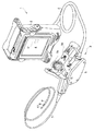
図1は、本実施の形態に係わる内視鏡の外観構成図である。
先端部8の基端側には、湾曲部9が設けられている。先端部8には、光学アダプタ10が取り付け可能になっている。操作部5には、フリーズボタン、記録指示ボタン(以下、RECボタン)、等の各種操作ボタンが、設けられている。
光学アダプタ10は、ステレオ計測用の光学アダプタであり、挿入部7の先端部8に装着することにより、内視鏡装置1は、ステレオ計測機能やステレオ観察機能を発揮することができる。
(撮像光学系の構成)
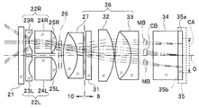
図2は、光学アダプタ10が先端に装着された先端部8の光学系の構成図である。
左眼光学系22Lは、先端から順に、平凹レンズ23Lと、平凸レンズ24Lを有している。平凸レンズ24Lの基端部分が、凸パワー部25Lを構成する。
光学アダプタ10は、第1の光路を形成する第1の光路形成光学系としての右眼光学系22Rと、第2の光路を形成する第2の光路形成光学系としての左眼光学系22Lを有する。
さらに、凸パワー部25Rは、凸状部を有し、第1の光路形成光学系である右眼光学系22R内に設けられ、第1の光路形成光学からの出射光を結像光学系36へ向けて出射するように配置されている。凸パワー部25Lも、凸状部を有し、第2の光路形成光学系である左眼光学系22L内に設けられ、第2の光路形成光学からの出射光を結像光学系36へ向けて出射するように配置されている。
平凹レンズ23Rは、第1の光路形成光学系である右眼光学系22Rの入射光側に設けられ、凹面を有する光学素子である。平凹レンズ23Lは、第2の光路形成光学系である左眼光学系22Lの入射光側に設けられ、凹面を有する光学素子である。
右眼光学系22Rと左眼光学系22Lの基端側には、先端から基端に向かって順に、メカシャッタ26と、複数のレンズからなる接合凸レンズ27が、光学アダプタ10内に配設されている。
右眼光学系22Rから出射した光束と左眼光学系22Lから出射した光は、それぞれ、メカシャッタ26の2つの開口を通って、結像光学系36に入射し、撮像素子35の撮像面上の共通の撮像領域に向けて出射される。
すなわち、結像光学系36は、第1の光路形成光学系である右眼光学系22Rからの出射光及び第2の光路形成光学系である左眼光学系22Lからの出射光を入射するように配置されている。撮像素子35は、結像光学系36から出射する光の結像位置に配設されている。
なお、接合凸レンズ27は、平凸レンズと凹平レンズを接合したレンズなどアダプタの基端側が平らなレンズで構成されていればよい。また、カバーガラスを光学アダプタ10と先端部8との間に配置されるように、光学アダプタ10内に設けてもよい。
以上のように、メカシャッタ26は、右眼光学系22R及び左眼光学系22Lの2つの光学系と、結像光学系36の間に配設されたシャッタである。結像光学系36は、右眼光学系22Rからの出射光及び左眼光学系22Lからの出射光を、撮像素子35の撮像面の共通の領域に結像するように構成されている。メカシャッタ26は、右眼光学系22Rからの出射光と左眼光学系22Lからの出射光とを交互に共通の領域に照射するように動作する。
なお、ここでは、メカシャッタ26は、右眼光学系22R及び左眼光学系22Lの2つの光学系と、結像光学系36の間に配設されているが、光学アダプタ10内において、凸パワー部25R、25Lの基端側であればどこでもよい。
撮像素子35の撮像面35bの中央部に、有効画素領域CAが設定されている。
なお、図2では、右眼光学系22Rを通る光のうち、中心光束CBと、2つの軸外光束MBの光路のみが示されている。中心光束CBは、物体からの光のうち視野中心から絞りを通る光束である。軸外光束MBは中心光束CB以外の光束である。
絞り部材26aの2つの開口26a1と26a2が、それぞれ右眼光学系22Rと左眼光学系22Lの2つの光路の絞りを構成する。円形の2つの開口26a1、26a2が、2つの光路のそれぞれの位置に配置されるように、メカシャッタ26は、光学アダプタ10内に配設される。
なお、絞り部材26aは、開口26a1を有する絞り部材と、開口26a2を有する絞り部材の2つの部材から構成されていてもよい。
光学アダプタ10内の図示しないコイルに発生する磁界により、磁石26mを有する遮蔽部材26bは、第1の位置と第2の位置のいずれかに位置可能となる。本体部2からの駆動信号が信号線(図示せず)を介してコイルに供給されることにより、遮蔽部材26bの移動が制御される。
絞り部材26Aaの開口26Aa1は、右眼光学系22Rの光路中に配置され、絞り部材26Abの開口26Ab1は、左眼光学系22Lの光路中に配置される。
図2に示すように、被写体から右眼光学系22Rに入射した光は、右眼光学系22Rの基端側に配設された絞り部材26aの開口26a1を通って結像光学系36に入射する。同様に、図2には示さないが、被写体から左眼光学系22Lに入射した光は、左眼光学系22Lの基端側に配設された絞り部材26aの開口26a2を通って結像光学系36に入射する。
以上のように、2つの光路形成光学系22R、22L、結像光学系36及び撮像素子35が撮像装置を構成する。
同様に、絞り部材26aの開口26a2の中心も、左眼光学系22Lの光軸上になく、左眼光学系22Lの光軸OLに対して結像光学系36の光軸側すなわち撮像素子35の中心軸O側にずれている。
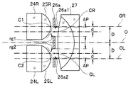
すなわち、絞り部材26aは、凸パワー部25Rから出射される光を透過する開口26a1と、凸パワー部25Lから出射される光を透過する開口26a2とを有し、第1の開口26a1の中心CRが右眼光学系22Rの光軸ORに対して結像光学系36の光軸O側に位置し、第2の開口26a2の中心CLが左眼光学系22Lの光軸OLに対して結像光学系36の光軸O側に位置している。
よって、距離dは、0<d<(D−(AP/2))である。
すなわち、光軸ORと光軸OLの各々と結像光学系36の光軸Oとの距離をDとし、第1及び第2の開口26a1、26a2の内径をAPとし、光軸ORと開口26a1の中心間の距離及び光軸OLと開口26a2の中心間の距離をdとしたとき、距離dは、0<d<(D−(AP/2))を満たす。
なお、ここでは、開口26a1及び26a2の内径は、APで同じであるが、互いに異なっていてもよい。
凸パワー部25Rの中心C1は、右眼光学系22Rの光軸OR上にある。凸パワー部25Rは、右眼光学系22Rを通った光を集光させる機能が有する。
撮像素子35に入射する光路を逆追跡により説明する。
左眼光学系22Lも同様である。図5において、光は、凸パワー部25Lの中心軸O側の領域rg2で屈折する。
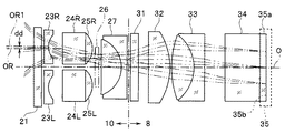
なお、変形例として、平凹レンズ23Rの光軸と右眼光学系22Rの光軸ORは一致している必要なく、同様に、平凹レンズ23Lの光軸と左眼光学系22Lの光軸OLは一致している必要はない。
すなわち、平凹レンズ23Rの光軸OR1は、光軸ORに対して結像光学系36の光軸Oとは反対側にずれ、平凹レンズ23Lの光軸も、光軸OLに対して結像光学系36の光軸Oとは反対側にずれている。
(第2の実施の形態)
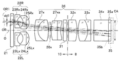
第1の実施の形態の内視鏡の撮像装置では、左右の対物光学系を通った2つの光は、撮像素子の撮像面上で共通の領域に結像するが、本実施の形態の内視鏡の撮像装置では、左右の対物光学系を通った2つの光は、撮像素子の撮像面上で異なる2つの領域で結像する。
光学アダプタ10の先端には、カバーガラス21が設けられている。カバーガラス21の後ろ側の光学アダプタ10の内部には、左右の対物光学系、すなわち右眼光学系22Rと左眼光学系22Lが配設されている。
左眼光学系22Lxは、先端から順に、平凹レンズ23Lxと、凹凸レンズ24Lxを有している。凹凸レンズ24Lxの基端部分が、凸パワー部25Lxを構成する。
右眼光学系22Rxと左眼光学系22Lxの基端側には、先端から基端に向かって順に、複数のレンズからなる接合凸レンズ27xと、絞り部材26xと、複数のレンズからなる接合凸レンズ27xaと、カバーガラス31が、光学アダプタ10内に配設されている。
結像光学系36は、右眼光学系22Rからの出射光及び左眼光学系22Lからの出射光を、撮像素子35の撮像面の互いに異なる2つの領域に結像するように構成されている。
なお、図7では、右眼光学系22Rを通る光のうち、中心光束CBと、2つの軸外光束MBの光路のみが示されている。
同様に、絞り部材26xの開口26a2の中心CLも、左眼光学系22Lの光軸OL上になく、左眼光学系22Lの光軸OLに対して結像光学系36の光軸すなわち撮像素子35の中心軸O側にずれている。
本実施の形態においても、第1の実施の形態と同様の効果を生じる。
その結果、より大きな視差量が確保できる。
なお、上述した各実施の形態及び各変形例において、より大きな視差量を確保するために、プリズムを追加してもよい。
図9において、平凹レンズ23Rxの光軸は、右眼光学系22Rxの光軸ORに対して結像光学系の中心軸(O)側にずれ、平凹レンズ23Lxの光軸は、左眼光学系22Lxの光軸OLに対して結像光学系の中心軸(O)側にずれて位置しているが、プリズム41により、2つの光路形成光学系の視差量は、十分に確保されている。
Claims (9)
- 第1の光路を形成する第1の光路形成光学系と、
第2の光路を形成する第2の光路形成光学系と、
前記第1の光路形成光学系からの出射光及び前記第2の光路形成光学系からの出射光を入射するように配置された結像光学系と、
凸状部を有し、前記第1の光路形成光学系内に設けられ、前記第1の光路形成光学系からの出射光を前記結像光学系へ向けて出射するように配置された第1の凸パワー部と、
凸状部を有し、前記第2の光路形成光学内に設けられ、前記第2の光路形成光学系からの出射光を前記結像光学系へ向けて出射するように配置された第2の凸パワー部と、
前記第1の凸パワー部から出射される光を透過する第1の開口と、前記第2の凸パワー部から出射される光を透過する第2の開口とを有し、前記第1の開口の中心が前記第1の光路形成光学系の第1の光軸に対して前記結像光学系の光軸側に位置し、前記第2の開口の中心が前記第2の光路形成光学系の第2の光軸に対して前記結像光学系の光軸側に位置する絞り部材と、
を有することを特徴とする撮像装置。 - 前記第1の光軸と前記第2の光軸の各々と前記結像光学系の光軸との距離をDとし、前記第1及び前記第2の開口の内径をAPとし、前記第1の光軸と前記第1の開口の中心間の距離及び前記第2の光軸と前記第2の開口の中心間の距離をdとしたとき、距離dは、0<d<(D−(AP/2))を満たすことを特徴とする請求項1に記載の撮像装置。
- 前記第1の凸パワー部と前記第2の凸パワー部は、前記結像光学系の光軸)に軸対称に配設されたことを特徴とする請求項1に記載の撮像装置。
- 前記第1の光路形成光学系の入射光側に設けられ、凹面を有する第1の光学素子と、
前記第2の光路形成光学系の入射光側に設けられ、凹面を有する第2の光学素子と、
を有し、
前記第1の光学素子の光軸は、前記第1の光軸に対して前記結像光学系の光軸とは反対側にずれ、
前記第2の光学素子の光軸は、前記第2の光軸に対して前記結像光学系の光軸とは反対側にずれていることを特徴とする請求項1に記載の撮像装置。 - 前記結像光学系から出射する光の結像位置に配設された撮像素子を有することを特徴とする請求項1に記載の撮像装置。
- 前記第1及び前記第2の光路形成光学系と、前記結像光学系の間に配設されたシャッタを有し、
前記結像光学系は、前記第1の光路形成光学系からの出射光及び前記第2の光路形成光学系からの出射光を、前記撮像素子の撮像面の共通の領域に結像するように構成され、
前記シャッタは、前記第1の光路形成光学系からの出射光と前記第2の光路形成光学系からの出射光とを交互に前記共通の領域に照射するように動作することを特徴とする請求項5に記載の撮像装置。 - 前記結像光学系は、前記第1の光路形成光学系からの出射光及び前記第2の光路形成光学系からの出射光を、前記撮像素子の撮像面の互いに異なる2つの領域に結像するように構成されていることを特徴とする請求項5に記載の撮像装置。
- 前記結像光学系は、プリズムを含むことを特徴とする請求項1に記載の撮像装置。
- 請求項1から8のいずれか1つに記載の撮像装置を有する内視鏡装置。
Priority Applications (2)
| Application Number | Priority Date | Filing Date | Title |
|---|---|---|---|
| JP2017105551A JP2018200417A (ja) | 2017-05-29 | 2017-05-29 | 撮像装置及び内視鏡装置 |
| US15/973,712 US11042021B2 (en) | 2017-05-29 | 2018-05-08 | Image pickup apparatus and endoscope apparatus |
Applications Claiming Priority (1)
| Application Number | Priority Date | Filing Date | Title |
|---|---|---|---|
| JP2017105551A JP2018200417A (ja) | 2017-05-29 | 2017-05-29 | 撮像装置及び内視鏡装置 |
Publications (1)
| Publication Number | Publication Date |
|---|---|
| JP2018200417A true JP2018200417A (ja) | 2018-12-20 |
Family
ID=64401428
Family Applications (1)
| Application Number | Title | Priority Date | Filing Date |
|---|---|---|---|
| JP2017105551A Pending JP2018200417A (ja) | 2017-05-29 | 2017-05-29 | 撮像装置及び内視鏡装置 |
Country Status (2)
| Country | Link |
|---|---|
| US (1) | US11042021B2 (ja) |
| JP (1) | JP2018200417A (ja) |
Cited By (1)
| Publication number | Priority date | Publication date | Assignee | Title |
|---|---|---|---|---|
| KR20210075456A (ko) * | 2019-12-13 | 2021-06-23 | 재단법인 오송첨단의료산업진흥재단 | 내시경용 초소형 광각 렌즈 시스템 및 이를 포함하는 내시경 |
Families Citing this family (4)
| Publication number | Priority date | Publication date | Assignee | Title |
|---|---|---|---|---|
| WO2020136802A1 (ja) * | 2018-12-27 | 2020-07-02 | オリンパス株式会社 | 光学装置および内視鏡 |
| WO2023003853A1 (en) * | 2021-07-21 | 2023-01-26 | Arizona Board Of Regents On Behalf Of The University Of Arizona | Multi-aperture monocular optical imaging system for multi-view image acquisition with depth perception and method |
| CN116841032B (zh) * | 2023-05-31 | 2024-06-04 | 极限人工智能有限公司 | 一种内窥镜镜头、电子内窥镜及图像采集方法 |
| CN116990942B (zh) * | 2023-09-27 | 2024-01-02 | 江西联创电子有限公司 | 光学镜头 |
Citations (2)
| Publication number | Priority date | Publication date | Assignee | Title |
|---|---|---|---|---|
| JP2010128354A (ja) * | 2008-11-28 | 2010-06-10 | Olympus Medical Systems Corp | ステレオ光学系、並びにそれを用いたステレオ計測用光学装置、ステレオ計測装置及びステレオ観察装置 |
| JP2016085414A (ja) * | 2014-10-28 | 2016-05-19 | オリンパス株式会社 | 撮像装置及びそれを用いた内視鏡 |
-
2017
- 2017-05-29 JP JP2017105551A patent/JP2018200417A/ja active Pending
-
2018
- 2018-05-08 US US15/973,712 patent/US11042021B2/en active Active
Patent Citations (2)
| Publication number | Priority date | Publication date | Assignee | Title |
|---|---|---|---|---|
| JP2010128354A (ja) * | 2008-11-28 | 2010-06-10 | Olympus Medical Systems Corp | ステレオ光学系、並びにそれを用いたステレオ計測用光学装置、ステレオ計測装置及びステレオ観察装置 |
| JP2016085414A (ja) * | 2014-10-28 | 2016-05-19 | オリンパス株式会社 | 撮像装置及びそれを用いた内視鏡 |
Cited By (2)
| Publication number | Priority date | Publication date | Assignee | Title |
|---|---|---|---|---|
| KR20210075456A (ko) * | 2019-12-13 | 2021-06-23 | 재단법인 오송첨단의료산업진흥재단 | 내시경용 초소형 광각 렌즈 시스템 및 이를 포함하는 내시경 |
| KR102285540B1 (ko) * | 2019-12-13 | 2021-08-04 | 재단법인 오송첨단의료산업진흥재단 | 내시경용 초소형 광각 렌즈 시스템 및 이를 포함하는 내시경 |
Also Published As
| Publication number | Publication date |
|---|---|
| US11042021B2 (en) | 2021-06-22 |
| US20180341100A1 (en) | 2018-11-29 |
Similar Documents
| Publication | Publication Date | Title |
|---|---|---|
| US5122650A (en) | Stereo video endoscope objective lens system | |
| EP0580772B1 (en) | Stereo video endoscope objective lens system | |
| US8648896B2 (en) | Stereoscopic optical system, and optical apparatus for stereoscopic measurement, stereoscopic measurement apparatus and stereoscopic observation apparatus each using the same | |
| JP4248771B2 (ja) | 内視鏡装置 | |
| US8081380B2 (en) | Stereoscopic zoom endoscope | |
| JP3580869B2 (ja) | 立体視内視鏡 | |
| US8149270B1 (en) | High resolution endoscope | |
| US11042021B2 (en) | Image pickup apparatus and endoscope apparatus | |
| EP0821805B1 (en) | Stereo video endoscope objective lens system | |
| US10613314B2 (en) | Oblique viewing endoscope and imaging system | |
| JP2013106189A (ja) | 撮像装置 | |
| US20200387007A1 (en) | Ophthalmic optical system, ophthalmic device, and ophthalmic system | |
| JP2001083400A (ja) | 撮像光学系 | |
| JP3540351B2 (ja) | 立体視硬性内視鏡 | |
| US11051680B1 (en) | Endoscope stereo imaging device | |
| US11249299B2 (en) | Stereoscopic vision optical system and endoscope using the same | |
| CN121285324A (zh) | 3d视频内窥镜 | |
| JP3668257B2 (ja) | 複数視野方向型内視鏡 | |
| JP7714171B2 (ja) | 硬性鏡装置 | |
| JP2013094259A (ja) | 内視鏡 | |
| JP3559341B2 (ja) | 立体視内視鏡 | |
| US11933961B2 (en) | Stereoscopic vision endoscope objective optical system and endoscope using the same | |
| US20200201021A1 (en) | Endoscope objective lens unit and endoscope | |
| WO2020225924A1 (ja) | 広角光学系、撮像装置、及び撮像システム | |
| JP2020012896A (ja) | 撮像光学系及び内視鏡 |
Legal Events
| Date | Code | Title | Description |
|---|---|---|---|
| A621 | Written request for application examination |
Free format text: JAPANESE INTERMEDIATE CODE: A621 Effective date: 20200424 |
|
| RD02 | Notification of acceptance of power of attorney |
Free format text: JAPANESE INTERMEDIATE CODE: A7422 Effective date: 20200424 |
|
| A977 | Report on retrieval |
Free format text: JAPANESE INTERMEDIATE CODE: A971007 Effective date: 20210224 |
|
| A131 | Notification of reasons for refusal |
Free format text: JAPANESE INTERMEDIATE CODE: A131 Effective date: 20210302 |
|
| A521 | Request for written amendment filed |
Free format text: JAPANESE INTERMEDIATE CODE: A523 Effective date: 20210427 |
|
| A131 | Notification of reasons for refusal |
Free format text: JAPANESE INTERMEDIATE CODE: A131 Effective date: 20210817 |
|
| A02 | Decision of refusal |
Free format text: JAPANESE INTERMEDIATE CODE: A02 Effective date: 20220301 |