JP2018201746A - sewing machine - Google Patents
sewing machine Download PDFInfo
- Publication number
- JP2018201746A JP2018201746A JP2017108915A JP2017108915A JP2018201746A JP 2018201746 A JP2018201746 A JP 2018201746A JP 2017108915 A JP2017108915 A JP 2017108915A JP 2017108915 A JP2017108915 A JP 2017108915A JP 2018201746 A JP2018201746 A JP 2018201746A
- Authority
- JP
- Japan
- Prior art keywords
- sewing
- sewing machine
- needle
- movement amount
- detection unit
- Prior art date
- Legal status (The legal status is an assumption and is not a legal conclusion. Google has not performed a legal analysis and makes no representation as to the accuracy of the status listed.)
- Granted
Links
Images




Classifications
-
- D—TEXTILES; PAPER
- D05—SEWING; EMBROIDERING; TUFTING
- D05B—SEWING
- D05B19/00—Program-controlled sewing machines
- D05B19/02—Sewing machines having electronic memory or microprocessor control unit
- D05B19/12—Sewing machines having electronic memory or microprocessor control unit characterised by control of operation of machine
- D05B19/14—Control of needle movement, e.g. varying amplitude or period of needle movement
-
- D—TEXTILES; PAPER
- D05—SEWING; EMBROIDERING; TUFTING
- D05B—SEWING
- D05B21/00—Sewing machines with devices for automatically controlling movement of work-carrier relative to stitch-forming mechanism in order to obtain particular configuration of seam, e.g. program-controlled for sewing collars or for attaching pockets
-
- D—TEXTILES; PAPER
- D05—SEWING; EMBROIDERING; TUFTING
- D05B—SEWING
- D05B1/00—General types of sewing apparatus or machines without mechanism for lateral movement of the needle or the work or both
-
- D—TEXTILES; PAPER
- D05—SEWING; EMBROIDERING; TUFTING
- D05B—SEWING
- D05B69/00—Driving-gear; Control devices
- D05B69/02—Mechanical drives
-
- D—TEXTILES; PAPER
- D05—SEWING; EMBROIDERING; TUFTING
- D05B—SEWING
- D05B69/00—Driving-gear; Control devices
- D05B69/14—Devices for changing speed or for reversing direction of rotation
- D05B69/18—Devices for changing speed or for reversing direction of rotation electric, e.g. foot pedals
-
- D—TEXTILES; PAPER
- D05—SEWING; EMBROIDERING; TUFTING
- D05B—SEWING
- D05B97/00—Hand sewing processes or apparatus for special work or not otherwise provided for
- D05B97/02—Hand-guided apparatus
Landscapes
- Engineering & Computer Science (AREA)
- Textile Engineering (AREA)
- Mechanical Engineering (AREA)
- Computer Hardware Design (AREA)
- Microelectronics & Electronic Packaging (AREA)
- Sewing Machines And Sewing (AREA)
Abstract
【課題】針落ち状態を避けて被縫製物の移動量を検出する。【解決手段】被縫製物Cの移動量を検出する移動量検出部21,22と、針棒13に上下動を付与する上軸の回転駆動源となるミシンモーター30と、上軸又はミシンモーターの出力軸の軸角度を検出する軸角度検出部31と、移動量検出部の検出に基づいてミシンモーターを制御し、一定の縫いピッチを維持する制御を行う制御装置90とを備え、制御装置は、軸角度検出部の検出に基づいて、縫い針12が布地Cに突き刺さっていない軸角度区間で移動量検出部により検出された被縫製物の移動量により、一定の縫いピッチを維持する制御を行う。【選択図】図3PROBLEM TO BE SOLVED: To detect a moving amount of a sewn object while avoiding a needle drop state. SOLUTION: A movement amount detection unit 21 and 22 for detecting the movement amount of a sewing object C, a sewing machine motor 30 which is a rotation drive source of an upper shaft for giving vertical movement to a needle rod 13, and an upper shaft or a sewing machine motor. The control device includes a shaft angle detection unit 31 that detects the shaft angle of the output shaft of the sewing machine, and a control device 90 that controls the sewing machine motor based on the detection of the movement amount detection unit to maintain a constant sewing pitch. Controls to maintain a constant sewing pitch based on the movement amount of the sewing object detected by the movement amount detection unit in the shaft angle section where the sewing needle 12 is not pierced by the fabric C based on the detection of the shaft angle detection unit. I do. [Selection diagram] Fig. 3
Description
本発明は、ミシンに対する相対的な被縫製物の移動量を検出するミシンに関する。 The present invention relates to a sewing machine that detects a movement amount of a sewing product relative to the sewing machine.
従来より、ミシンのフレームに固定装備された光学式のセンサーにより針板上の被縫製物の移動量を求め、一定の移動量で針落ちを行うようにミシンモーターの回転数を制御することにより、縫いピッチを一定に維持するミシンが知られている(例えば、特許文献1参照)。 Conventionally, the amount of movement of the sewing material on the throat plate is obtained by an optical sensor fixed to the sewing machine frame, and the number of movements of the sewing machine motor is controlled so that the needle drops with a certain amount of movement. A sewing machine that maintains a constant sewing pitch is known (see, for example, Patent Document 1).
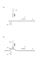
しかしながら、上記従来のミシンは、図7(A)に示すように、被縫製物に対して縫い針112が上方に位置している場合には、センサー121は被縫製物Cの移動量mを正しく検出することができるが、縫い針112が被縫製物Cに突き刺されると、被縫製物Cの移動が拘束されることから、センサー121は正確な被縫製物の移動量の検出を行うことができなかった。
特に、縫い針112が下死点を通過して上昇する際には、図7(B)に示すように、被縫製物Cが縫い針112と一緒に引き上げられることから、当該引き上げにより被縫製物Cに移動成分mfが発生し、センサー121は被縫製物の移動量の検出精度がさらに低下していた。
However, in the conventional sewing machine, as shown in FIG. 7A, when the
In particular, when the
本発明は、被縫製物の針落ちの影響を避けて被縫製物の移動量の検出を行うことをその目的とする。 An object of the present invention is to detect the amount of movement of a sewing product while avoiding the influence of needle drop of the sewing product.
請求項1記載の発明は、ミシンにおいて、
被縫製物の移動量を検出する移動量検出部と、
針棒に上下動を付与する上軸の回転駆動源となるミシンモーターと、
前記上軸又は前記ミシンモーターの出力軸の軸角度を検出する軸角度検出部と、
前記移動量検出部の検出に基づいて前記ミシンモーターを制御し、一定の縫いピッチを維持する制御を行う制御装置とを備えるミシンにおいて、
前記制御装置は、前記軸角度検出部の検出に基づいて、縫い針が布地に突き刺さっていない軸角度区間で前記移動量検出部により検出された前記被縫製物の移動量により、一定の縫いピッチを維持する制御を行う。
The invention according to claim 1 is a sewing machine,
A movement amount detection unit for detecting the movement amount of the workpiece,
A sewing machine motor serving as a rotational drive source for the upper shaft that imparts vertical movement to the needle bar;
An axis angle detector for detecting an axis angle of the upper shaft or the output shaft of the sewing machine motor;
In a sewing machine comprising a control device that controls the sewing machine motor based on detection of the movement amount detection unit and performs control to maintain a constant sewing pitch.
Based on the detection by the shaft angle detection unit, the control device may determine a constant sewing pitch based on a movement amount of the sewing product detected by the movement amount detection unit in an axis angle section where a sewing needle does not pierce the fabric. Control to maintain.
請求項2記載の発明は、請求項1記載のミシンにおいて、
前記制御装置は、縫い針が布地に突き刺さっていない軸角度区間のうち、所定の上軸角度の範囲を非検出区間と設定可能であり、前記非検出区間を除いた縫い針が布地に突き刺さっていない区間において前記移動量検出部により検出された前記被縫製物の移動量により、一定の縫いピッチを維持する制御を行うことを特徴とする。
The invention according to
The control device can set a range of a predetermined upper axis angle as a non-detection section among the axial angle sections in which the sewing needle is not pierced into the cloth, and the sewing needle excluding the non-detection section is pierced into the cloth. Control is performed to maintain a constant sewing pitch based on the movement amount of the sewing product detected by the movement amount detection unit in a non-interval.
請求項3記載の発明は、請求項1又は2記載のミシンにおいて、
前記ミシンの針落ち位置に対して前記被縫製物を手動にて移動させてフリーモーション縫いを行うことを特徴とする。
また、請求項4記載の発明は、請求項1又は2記載のミシンにおいて、
前記被縫製物に対して前記ミシンを手動にて移動させてフリーモーション縫いを行うことを特徴とする。
The invention according to claim 3 is the sewing machine according to
It is characterized in that free motion sewing is performed by manually moving the workpiece to the needle drop position of the sewing machine.
The invention according to claim 4 is the sewing machine according to
Free motion sewing is performed by manually moving the sewing machine with respect to the sewing object.
本発明は、制御装置が、縫い針が布地に突き刺さっていない軸角度区間において検出された被縫製物の移動量に基づいて一定の縫いピッチを維持する制御を行うので、より正確に被縫製物の移動量を検出することができ、より精度良く一定の縫いピッチを維持して縫製を行うことが可能となる。 In the present invention, the control device performs control to maintain a constant sewing pitch based on the movement amount of the sewing product detected in the axial angle section in which the sewing needle does not pierce the fabric, so that the sewing product can be more accurately performed. Thus, the sewing can be performed while maintaining a constant sewing pitch with higher accuracy.
[発明の実施形態の概略]
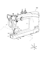
以下、図面を参照して、本発明にかかるミシンについて説明する。図1はミシン100の斜視図、図2はミシン100の制御系を示すブロック図である。
なお、本実施形態のミシン100は、専用の保持台に保持された被縫製物としての布地Cを作業者が手動操作により自由に移動させ、針落ち位置に対して布地Cを相対的に位置決めしながら縫製を行ういわゆるフリーモーション縫いを行うことが可能なミシンである。
なお、本実施形態では、保持台の図示及び構造の説明は周知の保持台と同じなので省略する。
[Outline of Embodiment of the Invention]
Hereinafter, a sewing machine according to the present invention will be described with reference to the drawings. FIG. 1 is a perspective view of the
In the
In the present embodiment, the illustration and description of the structure of the holding table are the same as those of the well-known holding table, and will be omitted.
ミシン100は、縫い針12を下端部に保持する針棒13を上下動させる針棒上下動機構と、縫い針12に通された上糸を捕捉して下糸に絡める釜機構と、上糸を引き上げて結節を形成する天秤機構と、上糸に所定の張力を付与する糸調子器と、これらを格納又は保持するミシンフレーム11と、各部の動作制御を行う制御部としての制御装置90とを備えている。
上記釜機構、天秤機構及び糸調子器は、ミシンにおける周知の構成と同一であることから詳細な説明は省略する。
The
Since the hook mechanism, the balance mechanism, and the thread tension device are the same as the well-known configuration in the sewing machine, detailed description thereof will be omitted.
ミシンフレーム11は、ミシン本体下部に位置するミシンベッド部と、ミシンベッド部の一端部から立設された立胴部と、立胴部からミシンベッド部と同じ方向に延出されたミシンアーム部とからなる。
以下の説明では、水平方向であってミシンベッド部111の長手方向に沿った方向をX軸方向、水平方向であってX軸方向に直交する方向をY軸方向、X軸方向及びY軸方向に直交する鉛直上下方向をZ軸方向とする。
The
In the following description, the horizontal direction and the direction along the longitudinal direction of the
針棒上下動機構は、縫製動作の駆動源となるミシンモーター30と、ミシンモーター30により回転駆動が行われる図示しない上軸と、上軸のトルクを上下の往復動作に変換して針棒13に付与する図示しないクランク機構とを備えている。
ミシンモーター30の出力軸には軸角度検出部としてのエンコーダー31が装備されており、出力軸の軸角度変化量に応じてパルス出力を行う。
ミシンモーター30の出力軸から上軸への伝達比は既知であり、制御装置90は、エンコーダー31のパルス出力からミシンモーター30の出力軸の軸角度を算出し、さらに、伝達比から上軸の軸角度を算出することができる。
なお、上軸にエンコーダーを設け、直接的に上軸の軸角度を検出しても良い。
The needle bar up-and-down moving mechanism converts the
The output shaft of the
The transmission ratio from the output shaft of the
An encoder may be provided on the upper shaft, and the shaft angle of the upper shaft may be directly detected.
また、ミシン100は、縫い針12の上昇時に布地Cから円滑に抜けるように布地Cを押さえる中押さえ14を備えている。この中押さえ14は中押さえ棒141の下端部に支持されている。そして、中押さえ14は、縫い針12を遊挿可能な小型の枠体であり、針棒13を上下動させる駆動源であるミシンモーター30(図2参照)から周知の伝達機構を介して動力を得て、針棒13よりも小さい振幅で上下動を行う。なお、この中押さえ14は、針棒13とは位相がずれており、縫い針12の上昇時に中押さえ14が下降する。また、中押さえ14は、布地Cの移動を妨げないようにその下死点位置において針板16に対して幾分隙間ができるように設定されている。
The
また、ミシン100は、図2に示すように、縫製終了時に縫い糸を切断する糸切り装置43を備えている。この糸切り装置43は、針板16の下側において針穴の真下を通過するように往復回動を行うことが可能な動メスと、動メスとの協働により縫い糸を切断する固定メスと(何れも図示略)、動メスを往復回動させる糸切りモーター431と、制御装置90の指令に従って糸切りモーター431を駆動させる駆動回路432とを備えている。
Further, as shown in FIG. 2, the
また、ミシンベッド部111には、針板16の針穴(図示略)におけるX軸方向の両側に、手動で送られる布地Cに対するミシン100の針落ち位置の近傍であって、水平面(X−Y平面)におけるその相対的な移動量を検出する移動量検出部としての第一と第二のセンサー21,22がそれぞれ設けられている。
これらの第一と第二のセンサー21,22は、針板16の上面から上方に向けられた状態で固定装備された二次元のイメージセンサーである。
Further, the sewing
These first and
さらに、第一と第二のセンサー21,22は、何れも光軸がZ軸方向に平行であって、針棒13の中心線を含む平面を基準に対称となるように配置されている。
これらのセンサー21,22の分解能はいずれも3[μm]である。また、それぞれのセンサー21,22は、針板16上の布地Cの下面を随時検出しており、その検出データを併設された処理装置23に入力する。
なお、センサー21,22の分解能の数値は一例であって上記数値に限定されない。
Further, the first and
The resolution of these
In addition, the numerical value of the resolution of the
第一及び第二のセンサー21,22に併設された処理装置23は、各センサー21,22から随時入力される連続的な検出信号から、布地Cの移動量について分解能である3[μm]の変化を生じる度にパルス信号を制御装置90に入力する。
なお、処理装置23は、第一及び第二のセンサー21,22のいずれか一方をメイン、他方をサブと予め決めており、メインのセンサーの検出に基づくパルス信号を制御装置90に入力し、メインのセンサーにエラーが生じた場合にはサブのセンサーの検出に基づくパルス信号を制御装置90に入力する。
The
In addition, the
[ミシンの制御系]
ミシン100は、その各構成の動作制御を行う制御装置90を備え、当該制御装置90に対して、前述したミシンモーター30及びそのエンコーダー31が駆動回路32を介して接続されている。
また、制御装置90に対して、前述した糸切り装置43の糸切りモーター431が駆動回路432を介して接続され、前述した第一及び第二のセンサー21,22は処理装置23を介して接続されている。
[Sewing machine control system]
The
The
また、制御装置90に対して、ミシンの操作者がミシンに対する操作入力を行う操作手段としての操作パネル41と、縫製を開始するスタートボタン42と、ミシンモーター30を駆動させるペダル44とが、それぞれ図示しないインターフェイスを介して接続されている。
操作パネル41からは、例えば、一針ごとの縫い目の長さである縫いピッチの設定が行われる。また、操作パネル41には表示部が設けられ、各種の情報の表示が行われる。
Further, an
From the
制御装置90は、主に、ミシンモーター30の制御を行うCPU91と、CPU91の作業エリアとなるRAM92と、CPU91が処理するプログラムが記憶されたROM93と、演算処理に用いられるデータが記憶されるとともに当該データを書き換え可能に構成された記憶部としてのEEPROM94とを備えている。
The
[縫製時の動作制御]
次に、ミシン100の制御装置90が行う縫製動作制御について説明する。
前述したように、ミシン100は、縫製作業者が針落ち位置に対して、布地Cを任意に移動させながら縫製が行われる。
制御装置90は、ミシン操作者の手によって任意に布地Cが移動操作された際に、操作パネル41から設定された一定の縫いピッチを維持して縫いが行われるようにミシンモーター30の回転速度を制御する。
[Operation control during sewing]
Next, sewing operation control performed by the
As described above, the
The
即ち、制御装置90は、第一又は第二のセンサー21,22の検出に基づいて入力されるパルスの時間間隔(パルス間隔とする)から布地Cの移動速度を算出し、さらに、当該移動速度で設定された縫いピッチ分の移動が行われるまでに上軸が一回転を行うためのミシンモーター30の回転速度を算出し、当該回転速度となるように制御する。なお、第一又は第二のセンサー21,22の検出に基づくミシンモーター30の回転速度の算出は、微小な時間周期で繰り返し実行される。
That is, the
ところで、縫い針12が布地Cに突き刺さってから抜けきるまでの間は、布地Cの移動が縫い針12に拘束され、正確な布地Cの移動速度を求めることが困難となる。
図3は、下降する縫い針12が針板16に到達し、針棒下死点を通過して上昇する縫い針12が針板16に到達するまでの上軸角度を示す説明図であり、針棒上死点となる上軸角度を0°、針棒下死点となる上軸角度を180°としている。
この図に示すように、下降する縫い針12が針板16に到達する上軸角度は90°であり、針棒下死点を通過して上昇する縫い針12が針板16に到達する上軸角度は270°である。
By the way, the movement of the fabric C is restrained by the
FIG. 3 is an explanatory view showing the upper shaft angle until the lowering
As shown in this figure, the upper shaft angle at which the descending
従って、制御装置90は、正確な布地Cの移動速度を求めることが困難となる上軸角度90°以上270°以下の軸角度区間(非検出区間Nとする)を避けて、上軸角度270°を超えて90°未満の軸角度区間(検出区間Sとする)で第一又は第二のセンサー21,22の処理装置23から入力されるパルスの時間間隔から布地Cの移動速度を決定する。
なお、「検出区間」とは第一又は第二のセンサー21,22の検出に基づいてミシンモーター30の回転速度制御を行う上軸角度区間を意味し、「非検出区間」とは第一又は第二のセンサー21,22の検出に基づくことなくミシンモーター30の回転速度制御を行う上軸角度区間を意味する。
なお、この場合、上軸角度が非検出区間Nの間は布地Cの移動速度が求められなくなる。従って、制御装置90は、非検出区間Nにおける布地Cの移動速度は、例えば、非検出区間Nに突入する直前に求められた移動速度で布地Cが移動しているものとみなして、ミシンモーター30の回転速度を制御する。
なお、非検出区間Nにおける布地Cの移動速度は、非検出区間Nに突入する直前に求められた布地Cの移動速度ではなく、妥当な他の値を採用しても良い。例えば、検出区間Sで算出された複数の布地Cの移動速度の平均値を採用しても良い。
さらには、直前に求められた布地Cの移動速度や平均化された布地Cの移動速度に対して所定の係数を乗じたものを非検出区間Nにおける布地Cの移動速度としてミシンモーター30の回転速度を制御しても良い。
Therefore, the
The “detection section” means an upper shaft angle section that controls the rotational speed of the
In this case, the movement speed of the fabric C cannot be obtained while the upper axis angle is in the non-detection section N. Therefore, the
Note that the movement speed of the fabric C in the non-detection section N is not the movement speed of the cloth C obtained immediately before entering the non-detection section N, and may be another appropriate value. For example, you may employ | adopt the average value of the moving speed of the some fabric C calculated in the detection area S. FIG.
Further, the rotation speed of the
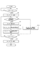
図4は縫製時に制御装置90のCPU91が実行する処理を示すフローチャートである。これに基づいて、縫製時にCPU91が実行する処理について詳細に説明する。
FIG. 4 is a flowchart showing processing executed by the
まず、CPU91は、当初、ペダル44の踏み込みの検出を行い(ステップS1)、検出されない場合には、再びペダル44の踏み込みの検出を行う(ステップS1:NO)。また、ペダル44の踏み込みを検出すると(ステップS1:YES)、ミシンモーター30の駆動を開始する(ステップS3)。
First, the
そして、CPU91は、エンコーダー31の出力から上軸角度が検出区間S内であるか否かを判定し(ステップS5)、検出区間S内である場合には(ステップS5:YES)、第一又は第二のセンサー21,22のパルスの時間間隔から布地Cの移動速度を算出し(ステップS7)、当該移動速度に対応するミシンモーター30の回転速度を算出する(ステップS9)。さらに、CPU91は、算出した回転速度となるようにミシンモーター30を制御する(ステップS11)。
その後、ステップS15に処理を進める。
Then, the
Thereafter, the process proceeds to step S15.
一方、CPU91は、エンコーダー31の出力が検出区間S外と判定した場合には(ステップS5:NO)、検出区間S内に算出された直近の回転速度となるようにミシンモーター30を制御する(ステップS13)。
その後、ステップS15に処理を進める。
On the other hand, if the
Thereafter, the process proceeds to step S15.
ステップS15では、ペダル44の踏み込みの検出が行われ、ペダル44の踏み込みが継続されている場合には(ステップS15:NO)、ステップS5に処理を戻し、再び、上軸角度が検出区間S内であるか否かの判定が行われる。
また、ペダル44の踏み込みが解除された場合には(ステップS15:YES)、CPU91は、ミシンモーター30を停止させて動作制御を終了する。
In step S15, the depression of the
When the depression of the
[発明の実施形態の技術的効果]
上記ミシン100では、制御装置90が、軸角度検出部としてのエンコーダー31の検出に基づいて、縫い針12が布地Cに突き刺さっていない軸角度区間である検出区間Sで移動量検出部としての第一又は第二のセンサー21,22により検出された布地Cの移動量により、一定の縫いピッチを維持する制御を行っている。
このため、縫い針12が布地Cに突き刺さる軸角度区間である非検出区間Nにおいて検出される不正確な布地Cの移動量の影響を低減してミシンモーター30を制御することができ、より正確に目標となる縫いピッチを維持して縫製を行うことが可能となる。
従って、ミシン100のように、布地Cを手動にて移動させてフリーモーション縫いを行う場合に、特に縫い品質の向上を図ることが可能となる。
[Technical effects of the embodiment of the invention]
In the
For this reason, it is possible to control the
Therefore, when performing free motion sewing by manually moving the fabric C as in the
[上軸角度の検出区間の範囲について]
なお、検出区間Sの設定は図3に示す90〜270°の区間に限定されず、より狭い範囲としても良い。本実施形態では、縫い針12が針板16以下に位置する上軸角度範囲を、縫い針12が布地Cに突き刺さってから抜けきるまでの区間としたが、例えば、図5に示すように、布地Cの厚さを考慮して縫い針12が針板16よりも高い位置となる上軸角度の範囲を検出区間Sとしても良い。
[Upper angle detection range]
The setting of the detection section S is not limited to the 90 to 270 ° section shown in FIG. 3 and may be a narrower range. In the present embodiment, the upper shaft angle range in which the
また、検出区間Sは一つに限らず複数設定しても良い。例えば、縫い針12が布地Cに突き刺さっている上軸角度の範囲以外にも、布地Cの移動速度の検出精度が低下する上軸角度が、例えば、理論的又は経験則的に既知である場合には、そのような上軸角度の範囲を新たに非検出区間とし、これに伴い、検出区間を複数にしても良い。
例えば、縫い針12の上死点の周辺は、布地Cの検出移動速度に乱れが生じることが既知であるような場合に、図6に示すように、縫い針12が布地Cに突き刺さる上軸角度を第一の非検出区間N1とし、縫い針12の上死点の周辺を第二の非検出区間N2とする。そして、第一の非検出区間N1と第二の非検出区間N2の間の上軸角度を第一の検出区間S1と第二の検出区間S2としても良い。
これらにより、不正確な布地の移動量の影響を低減してミシンモーター30を制御し、より正確に目標となる縫いピッチを維持して縫製を行うことが可能となる。
The number of detection sections S is not limited to one, and a plurality of detection sections S may be set. For example, in addition to the range of the upper axis angle at which the
For example, in the vicinity of the top dead center of the
Thus, it is possible to control the
また、操作パネル41等の設定手段により、縫い針12が布地Cに突き刺さっていない上軸角度の範囲内で任意の上軸角度の範囲を非検出区間に設定可能としても良い。また、検出区間の数も任意に設定可能としても良い。
Further, any upper axis angle range within the range of the upper axis angle at which the
[その他]
上記ミシン100は、ミシン100に対して布地Cを手動で移動させる場合を例示したが、布地Cに対してミシン100を手動で移動させてフリーモーション縫いを行うミシンでもよいことは言うまでもない。
[Others]
The
12 縫い針
13 針棒
16 針板
21 第一のセンサー(移動量検出部)
22 第二のセンサー(移動量検出部)
30 ミシンモーター
31 エンコーダー(軸角度検出部)
90 制御装置
100 ミシン
C 布地(被縫製物)
S,S1,S2 検出区間
N,N1,N2 非検出区間
12
22 Second sensor (movement amount detector)
30
90
S, S1, S2 detection interval N, N1, N2 non-detection interval
Claims (4)
針棒に上下動を付与する上軸の回転駆動源となるミシンモーターと、
前記上軸又は前記ミシンモーターの出力軸の軸角度を検出する軸角度検出部と、
前記移動量検出部の検出に基づいて前記ミシンモーターを制御し、一定の縫いピッチを維持する制御を行う制御装置とを備えるミシンにおいて、
前記制御装置は、前記軸角度検出部の検出に基づいて、縫い針が布地に突き刺さっていない軸角度区間で前記移動量検出部により検出された前記被縫製物の移動量により、一定の縫いピッチを維持する制御を行うことを特徴とするミシン。 A movement amount detection unit for detecting the movement amount of the workpiece,
A sewing machine motor serving as a rotational drive source for the upper shaft that imparts vertical movement to the needle bar;
An axis angle detector for detecting an axis angle of the upper shaft or the output shaft of the sewing machine motor;
In a sewing machine comprising a control device that controls the sewing machine motor based on detection of the movement amount detection unit and performs control to maintain a constant sewing pitch.
Based on the detection by the shaft angle detection unit, the control device may determine a constant sewing pitch based on a movement amount of the sewing product detected by the movement amount detection unit in an axis angle section where a sewing needle does not pierce the fabric. A sewing machine characterized by performing control to maintain
Priority Applications (2)
| Application Number | Priority Date | Filing Date | Title |
|---|---|---|---|
| JP2017108915A JP6962713B2 (en) | 2017-06-01 | 2017-06-01 | sewing machine |
| US15/993,979 US10767292B2 (en) | 2017-06-01 | 2018-05-31 | Sewing machine |
Applications Claiming Priority (1)
| Application Number | Priority Date | Filing Date | Title |
|---|---|---|---|
| JP2017108915A JP6962713B2 (en) | 2017-06-01 | 2017-06-01 | sewing machine |
Publications (2)
| Publication Number | Publication Date |
|---|---|
| JP2018201746A true JP2018201746A (en) | 2018-12-27 |
| JP6962713B2 JP6962713B2 (en) | 2021-11-05 |
Family
ID=64458847
Family Applications (1)
| Application Number | Title | Priority Date | Filing Date |
|---|---|---|---|
| JP2017108915A Active JP6962713B2 (en) | 2017-06-01 | 2017-06-01 | sewing machine |
Country Status (2)
| Country | Link |
|---|---|
| US (1) | US10767292B2 (en) |
| JP (1) | JP6962713B2 (en) |
Families Citing this family (3)
| Publication number | Priority date | Publication date | Assignee | Title |
|---|---|---|---|---|
| CN110747587B (en) * | 2019-11-28 | 2021-06-22 | 杰克缝纫机股份有限公司 | Needle distance detection method, needle distance detection device, sewing machine and readable storage medium |
| JP2024165045A (en) * | 2023-05-16 | 2024-11-28 | 株式会社ジャノメ | sewing machine |
| JP2025009175A (en) * | 2023-07-07 | 2025-01-20 | 株式会社ジャノメ | sewing machine |
Family Cites Families (6)
| Publication number | Priority date | Publication date | Assignee | Title |
|---|---|---|---|---|
| DE3228789A1 (en) * | 1982-08-02 | 1984-02-02 | Quick-Rotan Elektromotoren GmbH, 6100 Darmstadt | DRIVE AND CONTROL DEVICE FOR SEWING MACHINES, SEWING MACHINES AND THE LIKE |
| DE3236932A1 (en) * | 1982-10-06 | 1984-04-12 | Dürkoppwerke GmbH, 4800 Bielefeld | METHOD AND POSITIONING DEVICE FOR PLACING THE LAST NEEDLE PUNCH AT A PRE-DETERMINED POINT IN THE SEWING MATERIAL |
| DE3402224A1 (en) * | 1984-01-24 | 1985-07-25 | Kochs Adler Ag, 4800 Bielefeld | SEWING MACHINE |
| JP4724938B2 (en) | 2001-03-29 | 2011-07-13 | ブラザー工業株式会社 | sewing machine |
| US7373891B2 (en) * | 2004-05-14 | 2008-05-20 | Koerner Ralph J | Quilting method and apparatus using frame with motion detector |
| JP6324971B2 (en) * | 2013-09-09 | 2018-05-16 | エヌエスディ株式会社 | sewing machine |
-
2017
- 2017-06-01 JP JP2017108915A patent/JP6962713B2/en active Active
-
2018
- 2018-05-31 US US15/993,979 patent/US10767292B2/en active Active
Also Published As
| Publication number | Publication date |
|---|---|
| US20180347087A1 (en) | 2018-12-06 |
| JP6962713B2 (en) | 2021-11-05 |
| US10767292B2 (en) | 2020-09-08 |
Similar Documents
| Publication | Publication Date | Title |
|---|---|---|
| US10870938B2 (en) | Sewing machine | |
| JP6680539B2 (en) | sewing machine | |
| JP4364115B2 (en) | sewing machine | |
| CN1995519A (en) | Cloth-feeding device of sewing machine | |
| CN105908395A (en) | Sewing machine | |
| JP6962713B2 (en) | sewing machine | |
| CN105887343B (en) | The control method of sewing machine and sewing machine | |
| JP6894240B2 (en) | sewing machine | |
| JP2002292175A (en) | Sewing machine | |
| US20190352823A1 (en) | Sewing machine | |
| TW200938680A (en) | Automatic needlework sewing machine | |
| JP6867139B2 (en) | Sewing machine bobbin winder and sewing machine | |
| JP5130091B2 (en) | Cloth cutting device | |
| JP2018015466A (en) | Sewing apparatus and method for controlling sewing apparatus | |
| JP2005087251A (en) | sewing machine | |
| JP5013780B2 (en) | Sewing sewing machine | |
| JP7540179B2 (en) | Sewing equipment | |
| JP6727832B2 (en) | sewing machine | |
| JP5544057B2 (en) | sewing machine | |
| JP7181117B2 (en) | sewing machine | |
| JP2007195682A (en) | sewing machine | |
| JP2010011908A (en) | Buttonhole sewing machine | |
| JP2002306873A (en) | Staggered sewing machine |
Legal Events
| Date | Code | Title | Description |
|---|---|---|---|
| A621 | Written request for application examination |
Free format text: JAPANESE INTERMEDIATE CODE: A621 Effective date: 20200524 |
|
| A977 | Report on retrieval |
Free format text: JAPANESE INTERMEDIATE CODE: A971007 Effective date: 20210426 |
|
| A131 | Notification of reasons for refusal |
Free format text: JAPANESE INTERMEDIATE CODE: A131 Effective date: 20210601 |
|
| A521 | Request for written amendment filed |
Free format text: JAPANESE INTERMEDIATE CODE: A523 Effective date: 20210802 |
|
| TRDD | Decision of grant or rejection written | ||
| A01 | Written decision to grant a patent or to grant a registration (utility model) |
Free format text: JAPANESE INTERMEDIATE CODE: A01 Effective date: 20210928 |
|
| A61 | First payment of annual fees (during grant procedure) |
Free format text: JAPANESE INTERMEDIATE CODE: A61 Effective date: 20211014 |
|
| R150 | Certificate of patent or registration of utility model |
Ref document number: 6962713 Country of ref document: JP Free format text: JAPANESE INTERMEDIATE CODE: R150 |