JP2018503473A - A surface cleaning head including an openable agitator chamber and a removable agitator for use in the openable agitator chamber - Google Patents
A surface cleaning head including an openable agitator chamber and a removable agitator for use in the openable agitator chamber Download PDFInfo
- Publication number
- JP2018503473A JP2018503473A JP2017540638A JP2017540638A JP2018503473A JP 2018503473 A JP2018503473 A JP 2018503473A JP 2017540638 A JP2017540638 A JP 2017540638A JP 2017540638 A JP2017540638 A JP 2017540638A JP 2018503473 A JP2018503473 A JP 2018503473A
- Authority
- JP
- Japan
- Prior art keywords
- agitator
- cleaning head
- driven
- stirrer
- surface cleaning
- Prior art date
- Legal status (The legal status is an assumption and is not a legal conclusion. Google has not performed a legal analysis and makes no representation as to the accuracy of the status listed.)
- Granted
Links
Images


Classifications
-
- A—HUMAN NECESSITIES
- A47—FURNITURE; DOMESTIC ARTICLES OR APPLIANCES; COFFEE MILLS; SPICE MILLS; SUCTION CLEANERS IN GENERAL
- A47L—DOMESTIC WASHING OR CLEANING; SUCTION CLEANERS IN GENERAL
- A47L9/00—Details or accessories of suction cleaners, e.g. mechanical means for controlling the suction or for effecting pulsating action; Storing devices specially adapted to suction cleaners or parts thereof; Carrying-vehicles specially adapted for suction cleaners
- A47L9/02—Nozzles
- A47L9/04—Nozzles with driven brushes or agitators
- A47L9/0461—Dust-loosening tools, e.g. agitators, brushes
- A47L9/0466—Rotating tools
- A47L9/0477—Rolls
-
- A—HUMAN NECESSITIES
- A47—FURNITURE; DOMESTIC ARTICLES OR APPLIANCES; COFFEE MILLS; SPICE MILLS; SUCTION CLEANERS IN GENERAL
- A47L—DOMESTIC WASHING OR CLEANING; SUCTION CLEANERS IN GENERAL
- A47L5/00—Structural features of suction cleaners
- A47L5/12—Structural features of suction cleaners with power-driven air-pumps or air-compressors, e.g. driven by motor vehicle engine vacuum
- A47L5/22—Structural features of suction cleaners with power-driven air-pumps or air-compressors, e.g. driven by motor vehicle engine vacuum with rotary fans
- A47L5/28—Suction cleaners with handles and nozzles fixed on the casings, e.g. wheeled suction cleaners with steering handle
- A47L5/30—Suction cleaners with handles and nozzles fixed on the casings, e.g. wheeled suction cleaners with steering handle with driven dust-loosening tools, e.g. rotating brushes
-
- A—HUMAN NECESSITIES
- A47—FURNITURE; DOMESTIC ARTICLES OR APPLIANCES; COFFEE MILLS; SPICE MILLS; SUCTION CLEANERS IN GENERAL
- A47L—DOMESTIC WASHING OR CLEANING; SUCTION CLEANERS IN GENERAL
- A47L9/00—Details or accessories of suction cleaners, e.g. mechanical means for controlling the suction or for effecting pulsating action; Storing devices specially adapted to suction cleaners or parts thereof; Carrying-vehicles specially adapted for suction cleaners
- A47L9/02—Nozzles
- A47L9/04—Nozzles with driven brushes or agitators
- A47L9/0405—Driving means for the brushes or agitators
- A47L9/0411—Driving means for the brushes or agitators driven by electric motor
-
- A—HUMAN NECESSITIES
- A47—FURNITURE; DOMESTIC ARTICLES OR APPLIANCES; COFFEE MILLS; SPICE MILLS; SUCTION CLEANERS IN GENERAL
- A47L—DOMESTIC WASHING OR CLEANING; SUCTION CLEANERS IN GENERAL
- A47L9/00—Details or accessories of suction cleaners, e.g. mechanical means for controlling the suction or for effecting pulsating action; Storing devices specially adapted to suction cleaners or parts thereof; Carrying-vehicles specially adapted for suction cleaners
- A47L9/02—Nozzles
- A47L9/04—Nozzles with driven brushes or agitators
- A47L9/0427—Gearing or transmission means therefor
- A47L9/0444—Gearing or transmission means therefor for conveying motion by endless flexible members, e.g. belts
-
- A—HUMAN NECESSITIES
- A47—FURNITURE; DOMESTIC ARTICLES OR APPLIANCES; COFFEE MILLS; SPICE MILLS; SUCTION CLEANERS IN GENERAL
- A47L—DOMESTIC WASHING OR CLEANING; SUCTION CLEANERS IN GENERAL
- A47L9/00—Details or accessories of suction cleaners, e.g. mechanical means for controlling the suction or for effecting pulsating action; Storing devices specially adapted to suction cleaners or parts thereof; Carrying-vehicles specially adapted for suction cleaners
- A47L9/02—Nozzles
- A47L9/04—Nozzles with driven brushes or agitators
- A47L9/0455—Bearing means therefor
-
- A—HUMAN NECESSITIES
- A47—FURNITURE; DOMESTIC ARTICLES OR APPLIANCES; COFFEE MILLS; SPICE MILLS; SUCTION CLEANERS IN GENERAL
- A47L—DOMESTIC WASHING OR CLEANING; SUCTION CLEANERS IN GENERAL
- A47L9/00—Details or accessories of suction cleaners, e.g. mechanical means for controlling the suction or for effecting pulsating action; Storing devices specially adapted to suction cleaners or parts thereof; Carrying-vehicles specially adapted for suction cleaners
- A47L9/02—Nozzles
- A47L9/04—Nozzles with driven brushes or agitators
- A47L9/0461—Dust-loosening tools, e.g. agitators, brushes
Landscapes
- Engineering & Computer Science (AREA)
- Mechanical Engineering (AREA)
- Nozzles For Electric Vacuum Cleaners (AREA)
- Electric Vacuum Cleaner (AREA)
- Filters For Electric Vacuum Cleaners (AREA)
- Food-Manufacturing Devices (AREA)
Abstract
表面清掃ヘッドは、ブラシロール等の取外し可能で回転可能な被駆動式攪拌機又は非被駆動式攪拌機を受取るように構成されてもよい。これらの攪拌機のいずれかは、くずを取除くため及び/又は攪拌機を取外すために開口可能攪拌機チャンバ内に配置されてもよい。開口可能攪拌機チャンバは、開口位置と閉鎖位置との間で移動可能である外部カバーによって覆われてもよい。取外し可能攪拌機の少なくとも一端は、外部カバーによって攪拌機チャンバ内に留められてもよい。封止部材は、外部カバーと表面清掃ヘッドハウジングとの間でかつ攪拌機チャンバの周囲の周りに配置されてもよい。異なる特性を有する異なる取外し可能攪拌機は、表面清掃ヘッド内で相互交換可能に使用されてもよい。
【選択図】図7AThe surface cleaning head may be configured to receive a removable and rotatable driven agitator such as a brush roll or a non-driven agitator. Any of these agitators may be placed in an openable agitator chamber to remove debris and / or to remove the agitator. The openable agitator chamber may be covered by an outer cover that is movable between an open position and a closed position. At least one end of the removable agitator may be retained in the agitator chamber by an external cover. A sealing member may be disposed between the outer cover and the surface cleaning head housing and around the periphery of the agitator chamber. Different removable agitators with different characteristics may be used interchangeably within the surface cleaning head.
[Selection] Figure 7A
Description
[技術分野]
本発明は、負圧掃除機に関し、より詳細には、開口可能攪拌機チャンバ及び開口可能攪拌機チャンバ内で使用するための取外し可能攪拌機を含む負圧掃除機表面清掃ヘッドに関する。
[Technical field]
The present invention relates to a vacuum cleaner, and more particularly to a vacuum cleaner surface cleaning head including an openable agitator chamber and a removable agitator for use in the openable agitator chamber.
[背景技術]
以下は、以下で論じるいずれのものも、従来技術の一部又は当業者の共通の一般的な知識の一部であるという承認ではない。
[Background technology]
The following is not an admission that anything discussed below is part of the prior art or part of the common general knowledge of those skilled in the art.
負圧掃除機としてより一般に知られている表面清掃装置は、少なくとも吸引を使用して種々の表面を清掃するために使用され得る。限定することなく、直立負圧掃除機、キャニスタ負圧掃除機、スティック負圧掃除機、及び集中負圧システムを含む種々のタイプの負圧掃除機が知られている。表面清掃装置は、通常、入口を有する表面清掃ヘッドを含む。一部の負圧掃除機は、表面清掃ヘッド以外の場所に動作コンポーネント(例えば、吸引モータ及び空気処理部材)の一部又は全てを含んで、表面清掃ヘッドがより軽く又はより小さくなることを可能にする。例えば、直立負圧掃除機は、表面清掃ヘッドに取り付けられる少なくとも空気処理部材を収容する直立セクションを含んでもよい。キャニスタ負圧掃除機は、少なくとも空気処理部材を収容するキャニスタ本体、並びに、柔軟ホース及びハンドルによって表面清掃ヘッドに接続される吸引モータを含んでもよい。別のタイプの負圧掃除機は、表面清掃ヘッド内に配置される吸引モータ及び空気処理部材(例えば、1つ又は複数のサイクロン)を含む。 A surface cleaning device, more commonly known as a vacuum cleaner, can be used to clean various surfaces using at least suction. Various types of negative pressure cleaners are known including, but not limited to, upright negative pressure cleaners, canister negative pressure cleaners, stick negative pressure cleaners, and centralized negative pressure systems. A surface cleaning device typically includes a surface cleaning head having an inlet. Some vacuum cleaners include some or all of the operating components (eg, suction motors and air handling members) in locations other than the surface cleaning head, allowing the surface cleaning head to be lighter or smaller To. For example, an upright negative pressure cleaner may include an upright section that houses at least an air treatment member attached to the surface cleaning head. The canister negative pressure cleaner may include a canister body containing at least an air treatment member, and a suction motor connected to the surface cleaning head by a flexible hose and handle. Another type of negative pressure cleaner includes a suction motor and an air handling member (eg, one or more cyclones) disposed within the surface cleaning head.
先に述べた負圧掃除機のうちの任意の負圧掃除機等の表面清掃装置は、同様に、表面を清掃することを促進するため、表面清掃ヘッド内に回転ブラシロール等の1つ又は複数の機械的攪拌機を含んでもよい。機械的攪拌機、特に回転ブラシロールに関する1つの問題は、もつれるくず(例えば、毛髪)を取除くことの困難さである。表面清掃ヘッドは、しばしば、攪拌機がもつれている又は詰まっているかどうかを判定し、くずを取除くためにひっくり返されなければならない。表面清掃ヘッドの内部に位置する機械的攪拌機からくずを取除くことは、同様に、特に表面清掃ヘッドの底部の制限された開口を通すと困難であり得る。くずを適切に取除くことができないことは、性能の低下、並びに、機械的攪拌機及び/又は負圧掃除機に対する損傷さえももたらし得る。 A surface cleaning device, such as any of the negative vacuum cleaners described above, similarly may be provided with one of a rotating brush roll or the like in the surface cleaning head to facilitate cleaning the surface, or A plurality of mechanical stirrers may be included. One problem with mechanical agitators, particularly rotating brush rolls, is the difficulty of removing tangles (eg, hair). The surface cleaning head often must be turned over to determine if the stirrer is tangled or clogged and to remove debris. Removing debris from a mechanical stirrer located inside the surface cleaning head can also be difficult, especially through a limited opening at the bottom of the surface cleaning head. Failure to properly remove litter can result in performance degradation and even damage to the mechanical stirrer and / or the vacuum cleaner.
一部の従来の負圧掃除機において、攪拌機は、同様に、全ての表面及び/又は条件に適さないことがあり得る。例えば、回転ブラシロールは、硬質な木製の床上ではなく、カーペット上での撹拌を提供するのが望ましいことがあり得る。これは、負圧掃除機の性能並びに多用途性を更に制限し得る。 In some conventional negative pressure cleaners, the agitator may be unsuitable for all surfaces and / or conditions as well. For example, it may be desirable for a rotating brush roll to provide agitation on the carpet rather than on a hard wooden floor. This can further limit the performance of the vacuum cleaner as well as the versatility.
[発明の概要]
一実施形態と矛盾することなく、負圧用の表面清掃ヘッドが提供される。表面清掃ヘッドは、前端部分、後端部分、側方に配置される側部、上側部分、及び、底側部分を有する清掃ヘッドハウジングを含む。攪拌機チャンバは、清掃ヘッドハウジングの前端部分内に配置される。攪拌機チャンバは、清掃ヘッドハウジングの上側部分を通る上部開口、及び、清掃ヘッドハウジングの底側部分を通る下部開口を有する。外部カバーは、攪拌機チャンバの上部開口を覆うため、清掃ヘッドハウジングに旋回可能に取り付けられる。外部カバーは、閉鎖位置と開口位置との間で旋回可能であり、攪拌機チャンバは、外部カバーが閉鎖位置にあるときに覆われ、外部カバーが開口位置にあるときに上部開口を通して到達可能である。回転可能な被駆動式攪拌機は、攪拌機チャンバ内に取外し可能に取り付けられ、それにより、攪拌機は、下部開口を通して表面に接触するように構成され、上部開口を通して取外されるように構成される。回転可能な被駆動式攪拌機は、被駆動端及び非被駆動端を含む。外部カバーは、攪拌機を攪拌機チャンバ内に保持するため、閉鎖位置で攪拌機の非被駆動端に係合し、外部カバーは、開口位置まで移動すると、攪拌機の非被駆動端から脱離する。攪拌機は、外部カバーが開口位置にあるとき、上部開口を通して到達可能でかつ取外し可能である。
[Summary of Invention]
A surface cleaning head for negative pressure is provided consistent with one embodiment. The surface cleaning head includes a cleaning head housing having a front end portion, a rear end portion, laterally disposed sides, an upper portion, and a bottom portion. The agitator chamber is disposed in the front end portion of the cleaning head housing. The agitator chamber has an upper opening through the upper portion of the cleaning head housing and a lower opening through the bottom portion of the cleaning head housing. An outer cover is pivotally attached to the cleaning head housing to cover the upper opening of the agitator chamber. The outer cover is pivotable between a closed position and an open position, and the agitator chamber is covered when the outer cover is in the closed position and reachable through the upper opening when the outer cover is in the open position . A rotatable driven agitator is removably mounted within the agitator chamber so that the agitator is configured to contact the surface through the lower opening and is configured to be removed through the upper opening. The rotatable driven stirrer includes a driven end and a non-driven end. The outer cover is engaged with the non-driven end of the stirrer in the closed position to hold the stirrer in the stirrer chamber, and the outer cover is detached from the non-driven end of the stirrer when moved to the open position. The agitator is reachable and removable through the top opening when the outer cover is in the open position.
別の実施形態と矛盾することなく、負圧用の表面清掃ヘッドが提供される。表面清掃ヘッドは、前端部分、後端部分、側方に配置される側部、上側部分、及び、底側部分を含む清掃ヘッドハウジングを含む。攪拌機チャンバは、清掃ヘッドハウジングの前端部分内に配置される。攪拌機チャンバは、清掃ヘッドハウジングの上側部分を通る上部開口、及び、清掃ヘッドハウジングの底側部分を通る下部開口を有する。外部カバーは、攪拌機チャンバの上部開口を覆うため、清掃ヘッドハウジングに旋回可能に取り付けられ、閉鎖位置と開口位置との間で移動可能である。攪拌機チャンバは、外部カバーが閉鎖位置にあるときに覆われ、外部カバーが開口位置にあるときに、上部開口を通して到達可能である。封止部材は、攪拌機チャンバの周りで清掃ヘッドハウジングと外部カバーとの間の境界を封止するため、攪拌機チャンバの周りで、外部カバーの内側部分及び清掃ヘッドハウジングの内側部分の少なくとも一方の周囲の周りに配置される。ラッチ機構は、外部カバーを閉鎖位置に保持するため、外部カバーと清掃ヘッドハウジングとの間の周囲の周りに複数の係合ポイントを設けるように構成される。回転可能な被駆動式攪拌機は、攪拌機チャンバ内に取り付けられ、それにより、攪拌機は、下部開口を通して表面に接触するように構成される。回転可能な被駆動式攪拌機は、被駆動端及び非被駆動端を含み、外部カバーが開口位置にあるとき、上部開口を通して到達可能である。 A surface cleaning head for negative pressure is provided consistent with other embodiments. The surface cleaning head includes a cleaning head housing that includes a front end portion, a rear end portion, laterally disposed sides, an upper portion, and a bottom portion. The agitator chamber is disposed in the front end portion of the cleaning head housing. The agitator chamber has an upper opening through the upper portion of the cleaning head housing and a lower opening through the bottom portion of the cleaning head housing. An outer cover is pivotally attached to the cleaning head housing to cover the upper opening of the agitator chamber and is movable between a closed position and an open position. The agitator chamber is covered when the outer cover is in the closed position and is reachable through the upper opening when the outer cover is in the open position. The sealing member seals the boundary between the cleaning head housing and the outer cover around the stirrer chamber, so that the sealing member surrounds at least one of the inner portion of the outer cover and the inner portion of the cleaning head housing around the stirrer chamber. Placed around. The latch mechanism is configured to provide a plurality of engagement points around the periphery between the outer cover and the cleaning head housing to hold the outer cover in the closed position. A rotatable driven stirrer is mounted in the stirrer chamber so that the stirrer is configured to contact the surface through the lower opening. The rotatable driven stirrer includes a driven end and a non-driven end and is reachable through the upper opening when the outer cover is in the open position.
一実施形態と矛盾することなく、負圧用の表面清掃ヘッドが提供される。表面清掃ヘッドは、前端部分、後端部分、側方に配置される側部、上側部分、及び、底側部分を有する清掃ヘッドハウジングを含む。攪拌機チャンバは、清掃ヘッドハウジングの前端部分内に配置され、清掃ヘッドハウジングの上側部分を通る上部開口、及び、清掃ヘッドハウジングの底側部分を通る下部開口を有する。攪拌機チャンバは、非被駆動側部及び被駆動側部を含む。表面清掃ヘッドは、同様に、攪拌機チャンバの被駆動側部における駆動部材、及び、駆動部材に駆動結合される攪拌機駆動モータを含む撹拌機駆動機構を含む。外部カバーは、攪拌機チャンバの上部開口を覆うため清掃ヘッドハウジングに取り付けられ、閉鎖位置と開口位置との間で移動可能であり、それにより、攪拌機チャンバは、外部カバーが閉鎖位置にあるときに覆われ、外部カバーが開口位置にあるときに上部開口を通して到達可能である。回転可能な被駆動式攪拌機は、攪拌機チャンバ内に取外し可能に取り付けられ、それにより、攪拌機は、下部開口を通して表面に接触するように構成され、外部カバーが開口位置にあるとき、上部開口を通して到達可能でありかつ取外し可能である。回転可能な被駆動式攪拌機は、攪拌機チャンバの非被駆動側部に取り付けられる非被駆動端を含み、それにより、攪拌機は、非被駆動端、及び、被駆動部材を含む被駆動端で自由に回転する。被駆動部材は、駆動機構の駆動部材に軸方向に嵌合すると共に係合し、それにより、駆動部材は、トルク及び回転を被駆動部材及び回転可能な被駆動式攪拌機に伝達する。 A surface cleaning head for negative pressure is provided consistent with one embodiment. The surface cleaning head includes a cleaning head housing having a front end portion, a rear end portion, laterally disposed sides, an upper portion, and a bottom portion. The agitator chamber is disposed in the front end portion of the cleaning head housing and has an upper opening through the upper portion of the cleaning head housing and a lower opening through the bottom portion of the cleaning head housing. The agitator chamber includes a non-driven side and a driven side. The surface cleaning head similarly includes a drive member on the driven side of the stirrer chamber and a stirrer drive mechanism including a stirrer drive motor that is drivingly coupled to the drive member. An outer cover is attached to the cleaning head housing to cover the top opening of the agitator chamber and is movable between a closed position and an open position so that the agitator chamber is covered when the outer cover is in the closed position. And is reachable through the top opening when the outer cover is in the open position. A rotatable driven agitator is removably mounted within the agitator chamber so that the agitator is configured to contact the surface through the lower opening and reaches through the upper opening when the outer cover is in the open position. It is possible and removable. The rotatable driven agitator includes a non-driven end attached to the non-driven side portion of the agitator chamber so that the agitator is free at the non-driven end and the driven end including the driven member. Rotate to. The driven member engages and engages with the driving member of the driving mechanism in the axial direction, whereby the driving member transmits torque and rotation to the driven member and the rotatable driven agitator.
別の実施形態と矛盾することなく、負圧用の表面清掃ヘッドが提供される。表面清掃ヘッドは、前端部分、後端部分、側方に配置される側部、上側部分、及び、底側部分を有する清掃ヘッドハウジングを含む。攪拌機チャンバは、清掃ヘッドハウジングの前端部分内に配置され、清掃ヘッドハウジングの上側部分を通る上部開口、及び、清掃ヘッドハウジングの底側部分を通る下部開口を有する。外部カバーは、攪拌機チャンバの上部開口を覆うため、清掃ヘッドハウジングに取り付けられる。外部カバーは、閉鎖位置と開口位置との間で移動可能であり、それにより、攪拌機チャンバは、外部カバーが閉鎖位置にあるときに覆われ、外部カバーが開口位置にあるときに上部開口を通して到達可能である。少なくとも第1及び第2の回転可能な被駆動式攪拌機は、攪拌機チャンバ内に取外し可能に取り付けられ、外部カバーが開口位置にあるときに上部開口を通して取外されるように構成され、それにより、回転可能な被駆動式攪拌機は相互交換可能である。第1の回転可能な被駆動式攪拌機は、第2の回転可能な被駆動式攪拌機と異なる撹拌特性を有する。 A surface cleaning head for negative pressure is provided consistent with other embodiments. The surface cleaning head includes a cleaning head housing having a front end portion, a rear end portion, laterally disposed sides, an upper portion, and a bottom portion. The agitator chamber is disposed in the front end portion of the cleaning head housing and has an upper opening through the upper portion of the cleaning head housing and a lower opening through the bottom portion of the cleaning head housing. An outer cover is attached to the cleaning head housing to cover the upper opening of the agitator chamber. The outer cover is movable between a closed position and an open position so that the agitator chamber is covered when the outer cover is in the closed position and reaches through the upper opening when the outer cover is in the open position Is possible. At least the first and second rotatable driven agitators are removably mounted within the agitator chamber and configured to be removed through the top opening when the outer cover is in the open position, thereby The rotatable driven stirrers are interchangeable. The first rotatable driven agitator has different agitation characteristics than the second rotatable driven agitator.
更なる実施形態と矛盾することなく、負圧用の表面清掃ヘッドが提供される。表面清掃ヘッドは、前端部分、後端部分、側方に配置される側部、上側部分、及び、底側部分を有する清掃ヘッドハウジングを有する。攪拌機チャンバは、清掃ヘッドハウジングの前端部分内に配置され、清掃ヘッドハウジングの上側部分を通る上部開口、及び、清掃ヘッドハウジングの底側部分を通る下部開口を有する。攪拌機チャンバは、回転可能な被駆動式攪拌機を、攪拌機が下部開口を通して表面に接触し上部開口を通して取外し可能であるように受取るように構成される。攪拌機チャンバは、回転可能な被駆動式攪拌機の非被駆動端を受取るための非被駆動側部、及び、回転可能な被駆動式攪拌機の被駆動端を受取るための被駆動側部を含む。表面清掃ヘッドは、同様に、攪拌機チャンバの被駆動側部における駆動部材、及び、駆動部材に駆動結合される攪拌機駆動モータを含む撹拌機駆動機構を含む。駆動部材は、回転可能な被駆動式攪拌機上で被駆動部材に軸方向に嵌合すると共に係合するよう構成され、それにより、駆動部材は、トルク及び回転を被駆動部材及び回転可能な被駆動式攪拌機に伝達する。外部カバーは、攪拌機チャンバの上部開口を覆うため清掃ヘッドハウジングに取り付けられる。外部カバーは、閉鎖位置と開口位置との間で移動可能であり、それにより、攪拌機チャンバは、外部カバーが閉鎖位置にあるときに覆われ、外部カバーが開口位置にあるときに上部開口を通して到達可能である。 A surface cleaning head for negative pressure is provided consistent with further embodiments. The surface cleaning head has a cleaning head housing having a front end portion, a rear end portion, side portions disposed on a side, an upper portion, and a bottom portion. The agitator chamber is disposed in the front end portion of the cleaning head housing and has an upper opening through the upper portion of the cleaning head housing and a lower opening through the bottom portion of the cleaning head housing. The agitator chamber is configured to receive a rotatable driven agitator such that the agitator contacts the surface through the lower opening and is removable through the upper opening. The agitator chamber includes a non-driven side for receiving a non-driven end of a rotatable driven agitator and a driven side for receiving a driven end of a rotatable driven agitator. The surface cleaning head similarly includes a drive member on the driven side of the stirrer chamber and a stirrer drive mechanism including a stirrer drive motor that is drivingly coupled to the drive member. The drive member is configured to engage and engage the driven member on the rotatable driven agitator in an axial direction so that the drive member can transmit torque and rotation to the driven member and the rotatable driven member. Transmit to the drive stirrer. An outer cover is attached to the cleaning head housing to cover the upper opening of the agitator chamber. The outer cover is movable between a closed position and an open position so that the agitator chamber is covered when the outer cover is in the closed position and reaches through the upper opening when the outer cover is in the open position Is possible.
一実施形態と矛盾することなく、負圧の表面清掃ヘッド内で使用するための取外し可能で回転可能な攪拌機組立体が提供される。取外し可能で回転可能な攪拌機組立体は、被駆動端及び非被駆動端を有する攪拌機本体と、被駆動端と非被駆動端との間で攪拌機本体の少なくとも一部分上に配置される少なくとも1つの撹拌要素とを含む。取外し可能で回転可能な攪拌機組立体は、攪拌機本体の被駆動端に配置される被駆動部材を更に含む。被駆動部材は、表面清掃ヘッド内の駆動機構上の駆動部材に軸方向に嵌合すると共に係合するように構成される。取外し可能で回転可能な攪拌機組立体は、攪拌機本体の非被駆動端から延びるアクスルと、アクスル上に回転可能に取り付けられるブッシングと、ブッシング上に取り付けられ、表面清掃ヘッドの攪拌機チャンバ内に回転することなく取り付けられるように構成されるエンドキャップとを更に含む。 Consistent with one embodiment, a removable and rotatable agitator assembly for use in a negative pressure surface cleaning head is provided. A removable and rotatable stirrer assembly includes a stirrer body having a driven end and a non-driven end, and at least one disposed on at least a portion of the stirrer body between the driven end and the non-driven end. A stirring element. The removable and rotatable stirrer assembly further includes a driven member disposed at a driven end of the stirrer body. The driven member is configured to be fitted and engaged with the driving member on the driving mechanism in the surface cleaning head in the axial direction. A removable and rotatable stirrer assembly includes an axle extending from an undriven end of the stirrer body, a bushing rotatably mounted on the axle, and mounted on the bushing and rotates into the agitator chamber of the surface cleaning head. And an end cap configured to be attached without any further.
別の実施形態と矛盾することなく、取外し可能で回転可能な攪拌機組立体は、被駆動端及び非被駆動端を有する攪拌機本体と、被駆動端と非被駆動端との間で攪拌機本体の少なくとも一部分上に配置される少なくとも1つの撹拌要素と、攪拌機本体の被駆動端に配置されるスプライン付き被駆動部材とを含む。スプライン付き被駆動部材は、表面清掃ヘッド内の駆動機構上のスプライン付き駆動部材に軸方向に嵌合すると共に係合するように構成される。 Consistent with another embodiment, a removable and rotatable stirrer assembly includes a stirrer body having a driven end and a non-driven end, and a stirrer body between the driven end and the non-driven end. At least one agitation element disposed on at least a portion and a splined driven member disposed at a driven end of the agitator body. The splined driven member is configured to fit and engage axially with the splined drive member on the drive mechanism within the surface cleaning head.
一実施形態と矛盾することなく、負圧用の表面清掃ヘッドが提供される。表面清掃ヘッドは、前端部分、後端部分、側方に配置される側部、上側部分、及び、底側部分を有する清掃ヘッドハウジングを含む。攪拌機チャンバは、清掃ヘッドハウジングの前端部分内に配置される。攪拌機チャンバは、清掃ヘッドハウジングの上側部分を通る上部開口と、及び、清掃ヘッドハウジングの底側部分を通る下部開口を有し、少なくとも1つの被駆動側部を含む。表面清掃ヘッドは、同様に、攪拌機チャンバの被駆動側部における駆動部材及び駆動部材に駆動結合される攪拌機駆動モータを含む攪拌機駆動機構を含む。駆動部材は、攪拌機チャンバ内に受取られると、回転可能な被駆動式攪拌機に係合し、回転可能な被駆動式攪拌機を駆動するように構成される。外部カバーは、攪拌機チャンバの上部開口を覆うため清掃ヘッドハウジングに取り付けられる。外部カバーは、閉鎖位置と開口位置との間で移動可能である。攪拌機チャンバは、外部カバーが閉鎖位置にあるときに覆われ、外部カバーが開口位置にあるときに上部開口を通して到達可能である。表面清掃ヘッドは、駆動部材に係合することなく、攪拌機チャンバ内に取外し可能に取り付けられる非被駆動式攪拌機を更に含み、それにより、非被駆動式攪拌機は、下部開口を通して表面に接触するように構成される。非被駆動式攪拌機は、外部カバーが開口位置にあるとき、上部開口を通して到達可能でありかつ取外し可能である。 A surface cleaning head for negative pressure is provided consistent with one embodiment. The surface cleaning head includes a cleaning head housing having a front end portion, a rear end portion, laterally disposed sides, an upper portion, and a bottom portion. The agitator chamber is disposed in the front end portion of the cleaning head housing. The agitator chamber has an upper opening through the upper portion of the cleaning head housing and a lower opening through the bottom portion of the cleaning head housing and includes at least one driven side. The surface cleaning head similarly includes a stirrer drive mechanism that includes a drive member on the driven side of the stirrer chamber and a stirrer drive motor that is drivingly coupled to the drive member. The drive member is configured to engage the rotatable driven agitator and drive the rotatable driven agitator when received in the agitator chamber. An outer cover is attached to the cleaning head housing to cover the upper opening of the agitator chamber. The outer cover is movable between a closed position and an open position. The agitator chamber is covered when the outer cover is in the closed position and is reachable through the upper opening when the outer cover is in the open position. The surface cleaning head further includes a non-driven agitator that is removably mounted within the agitator chamber without engaging the drive member, so that the undriven agitator contacts the surface through the lower opening. Configured. The undriven stirrer is reachable and removable through the top opening when the outer cover is in the open position.
別の実施形態と矛盾することなく、負圧用の表面清掃ヘッドが提供される。表面清掃ヘッドは、前端部分、後端部分、側方に配置される側部、上側部分、及び、底側部分を有する清掃ヘッドハウジングを含む。攪拌機チャンバは、清掃ヘッドハウジングの前端部分内に配置される。攪拌機チャンバは、清掃ヘッドハウジングの上側部分を通る上部開口、及び、清掃ヘッドハウジングの底側部分を通る下部開口を有し、少なくとも1つの被駆動側部を含む。表面清掃ヘッドは、同様に、攪拌機チャンバの被駆動側部における駆動部材、及び、駆動部材に駆動結合される攪拌機駆動モータを含む攪拌機駆動機構を含む。少なくとも1つの回転可能な被駆動式攪拌機は、攪拌機チャンバ内に取外し可能に取り付けられるように構成され、攪拌機駆動機構の駆動部材に係合するように構成され、それにより、駆動部材は、回転可能な被駆動式攪拌機を回転させる。少なくとも1つの非被駆動式攪拌機は、駆動部材に係合することなく、攪拌機チャンバ内に取外し可能に取り付けられるように構成され、それにより、非被駆動式攪拌機は、下部開口を通して表面に接触するように構成される。 A surface cleaning head for negative pressure is provided consistent with other embodiments. The surface cleaning head includes a cleaning head housing having a front end portion, a rear end portion, laterally disposed sides, an upper portion, and a bottom portion. The agitator chamber is disposed in the front end portion of the cleaning head housing. The agitator chamber has an upper opening through the upper portion of the cleaning head housing and a lower opening through the bottom portion of the cleaning head housing and includes at least one driven side. The surface cleaning head similarly includes a drive member on the driven side of the stirrer chamber and a stirrer drive mechanism including a stirrer drive motor that is drivingly coupled to the drive member. At least one rotatable driven agitator is configured to be removably mounted within the agitator chamber and configured to engage a drive member of the agitator drive mechanism, whereby the drive member is rotatable Rotate a driven agitator. At least one non-driven agitator is configured to be removably mounted within the agitator chamber without engaging the drive member so that the undriven agitator contacts the surface through the lower opening Configured as follows.
更なる実施形態と矛盾することなく、表面清掃ヘッドの攪拌機チャンバ内で使用するための取外し可能な非被駆動式攪拌機が提供される。取外し可能な非被駆動式攪拌機は、第1及び第2の細長い空気入口、空気出口、及び、少なくとも1つの空気入口と空気出口との間の空気経路を定める攪拌機本体を含む。細長い空気入口は、攪拌機本体の底側部分の少なくとも一部分に沿って配置され、空気出口は、攪拌機本体上で、表面清掃ヘッドの攪拌機チャンバ内で汚れ空気入口との係合を提供する位置に配置される。攪拌機本体の底側部分は、攪拌機チャンバの下部開口の幅に対応する幅を有する。攪拌機本体の第1及び第2の端は、攪拌機チャンバ内の駆動部材に係合することなく、攪拌機チャンバに係合するように構成される。取外し可能な非被駆動式攪拌機は、同様に、攪拌機本体の底側部分の少なくとも一方の側部でパッド支持部材上に支持される少なくとも1つの清掃パッドと、空気出口の周りの封止部とを含む。
これら及び他の特徴及び利点は、以下の詳細な説明を、図面と併せて読むことにより、良好に理解されるであろう。
本明細書に含まれる図面は、本明細書の教示の物品、方法、及び、装置の種々の例を説明するためのものであり、教示されるものの範囲をいずれの点でも制限することを意図するものでは無い。
Consistent with further embodiments, a removable, non-driven agitator is provided for use in the agitator chamber of the surface cleaning head. The removable non-driven agitator includes first and second elongated air inlets, an air outlet, and an agitator body that defines an air path between the at least one air inlet and the air outlet. The elongated air inlet is disposed along at least a portion of the bottom portion of the agitator body, and the air outlet is disposed on the agitator body in a position that provides engagement with the dirty air inlet within the agitator chamber of the surface cleaning head. Is done. The bottom side portion of the stirrer body has a width corresponding to the width of the lower opening of the stirrer chamber. The first and second ends of the agitator body are configured to engage the agitator chamber without engaging a drive member in the agitator chamber. The removable non-driven stirrer similarly includes at least one cleaning pad supported on the pad support member on at least one side of the bottom side portion of the stirrer body, and a seal around the air outlet including.
These and other features and advantages will be better understood when the following detailed description is read in conjunction with the drawings.
The drawings included herein are for purposes of illustrating various examples of the articles, methods, and apparatus taught herein and are intended to limit the scope of what is taught in any way. Not something to do.
[発明の詳細な説明]
本開示の複数の実施形態と矛盾しない表面清掃ヘッドは、ブラシロール等の取外し可能で回転可能な被駆動式攪拌機又は非被駆動式攪拌機を受取るように構成されてもよい。これらの攪拌機のいずれかは、くずを取除くため、及び/又は、攪拌機を取外すために、開口可能攪拌機チャンバ内に配置されてもよい。開口可能攪拌機チャンバは、開口位置と閉鎖位置との間で移動可能である外部カバーによって覆われてもよい。封止部材は、外部カバーと表面清掃ヘッドハウジングとの間で、かつ、攪拌機チャンバの周囲の周りに配置されてもよい。本開示の他の実施形態と矛盾しない表面清掃ヘッドは、被駆動端に軸方向に係合する駆動機構によって駆動される、ブラシロール等の取外し可能で回転可能な攪拌機を含む。取外し可能攪拌機は、外部カバーによって攪拌機チャンバ内に留められてもよい。表面清掃ヘッドは、同様に、使用中に攪拌機の目視検査を可能にするため1つ又は複数の透明領域(例えば、外部カバー上の窓)を含んでもよい。
Detailed Description of the Invention
A surface cleaning head consistent with embodiments of the present disclosure may be configured to receive a removable and rotatable driven or non-driven agitator such as a brush roll. Any of these agitators may be placed in the openable agitator chamber to remove debris and / or to remove the agitator. The openable agitator chamber may be covered by an outer cover that is movable between an open position and a closed position. A sealing member may be disposed between the outer cover and the surface cleaning head housing and around the periphery of the agitator chamber. A surface cleaning head consistent with other embodiments of the present disclosure includes a removable and rotatable stirrer, such as a brush roll, driven by a drive mechanism that axially engages the driven end. The removable agitator may be retained in the agitator chamber by an external cover. The surface cleaning head may also include one or more transparent areas (eg, windows on the outer cover) to allow visual inspection of the agitator during use.
非被駆動式攪拌機は、1つ又は複数の清掃ヘッドを支持する底側部分を含む攪拌機本体を含んでもよい。非被駆動式攪拌機本体は、同様に、1又は複数の空気入口、空気出口、及び、空気入口と空気出口との間に延びる空気経路を定め、表面清掃ヘッドを通る空気の通過を促進してもよい。異なる特性を有する異なる取外し可能攪拌機が、表面清掃ヘッドにおいて相互交換可能に使用されてもよい。 The undriven stirrer may include a stirrer body that includes a bottom portion that supports one or more cleaning heads. The undriven stirrer body similarly defines one or more air inlets, air outlets, and an air path extending between the air inlets and air outlets to facilitate the passage of air through the surface cleaning head. Also good. Different removable agitators with different characteristics may be used interchangeably in the surface cleaning head.
示す実施形態において、開口可能攪拌機チャンバ、外部カバー、取外し可能で回転可能な攪拌機、及び、本明細書で述べる他の特徴部は、「オールインヘッド(all in the head)」タイプの負圧掃除機において使用され、そのタイプの負圧掃除機では、流体(例えば、空気)の輸送及び処理のための機能又は作動コンポーネントは、実質的に全て、表面清掃ヘッド内に収容される。開口可能攪拌機チャンバ、外部カバー、取外し可能で回転可能な攪拌機、及び、本明細書で述べる他の特徴部は、同様に、限定することなく、直立負圧掃除機、キャニスタ負圧掃除機、スティック負圧掃除機、ロボット負圧掃除機、及び、集中負圧システムを含む任意のタイプの表面清掃装置又は負圧掃除機用の表面清掃ヘッドにおいて、本開示の範囲内で実装されてもよい。 In the illustrated embodiment, the openable agitator chamber, the outer cover, the removable rotatable agitator, and other features described herein are “all in the head” type negative pressure cleaning. In that type of negative pressure cleaner, substantially all of the functional or actuating components for transport and processing of fluid (eg, air) are contained within the surface cleaning head. The openable agitator chamber, outer cover, removable and rotatable agitator, and other features described herein are similarly, without limitation, an upright negative pressure cleaner, a canister negative pressure cleaner, a stick Any type of surface cleaning device or surface cleaning head for a negative pressure cleaner, including negative pressure cleaners, robotic negative pressure cleaners, and centralized negative pressure systems may be implemented within the scope of this disclosure.
本明細書で使用するとき、「表面清掃ヘッド(surface cleaning head)」は、吸引空気流、撹拌、又は、その組合せの使用によって清掃するため表面に接触するように構成されるデバイスを指す。表面清掃ヘッドは、スイベル接続部によって、表面清掃ヘッドを制御するための棒状部材に、旋回可能に、又は、操舵されるように結合されてもよいし、表面清掃ヘッドに固定され、動力化された部品を含んでいても良い。表面清掃ヘッドは、同様に、棒状部材又はハンドルなしで動作可能であってよい。本明細書で使用するとき、「攪拌機」は、表面清掃ヘッド内で吸引空気流内へのくずの移動を促進するため表面を撹拌することが可能な任意の要素、部材、又は構造を指す。本明細書で使用するとき、「透明な(transparent)」は、他の側の物体を見ることができるように十分な光が通過することを可能にすることができることを意味する。 As used herein, a “surface cleaning head” refers to a device configured to contact a surface for cleaning by use of a stream of suction air, agitation, or a combination thereof. The surface cleaning head may be pivotably or steerably coupled to a rod-like member for controlling the surface cleaning head by a swivel connection, and is fixed and motorized to the surface cleaning head. It may contain some parts. The surface cleaning head may likewise be operable without a bar or handle. As used herein, “stirrer” refers to any element, member, or structure that can stir a surface to facilitate litter movement into a suction air stream within a surface cleaning head. As used herein, “transparent” means that enough light can be allowed to pass through so that objects on the other side can be seen.
図1〜3Aを参照すると、表面清掃ヘッド100の一実施形態が、より詳細に示され述べられる。図2に詳細に示すように、棒状部材102は、スイベル接続部によって、表面清掃ヘッド100に操舵されるように結合され、一端にハンドル104を含んで、ユーザが使用中に表面清掃ヘッド100を制御することを可能にする。棒状部材102は、長さ調整を提供するため入れ子式構成を有してもよい。ハンドル104は、表面清掃ヘッド100の動作を制御するための制御部106(例えば、スイッチ及び/又は速度制御部)を含んでもよい。他の実施形態において、表面清掃ヘッド100は、(例えば、ロボット負圧表面清掃ヘッドにおいて、又は、動力化された表面清掃ヘッドにおいて)棒状部材及びハンドルを設けないで提供されても良い。
1-3A, one embodiment of the
表面清掃ヘッド100は、清掃ヘッドハウジング110、ハウジング110内に配置される攪拌機チャンバ120、及び、攪拌機チャンバ120内に配置される回転可能攪拌機130を含む。回転可能攪拌機130は、表面清掃ヘッド100の移動方向4に対して略垂直であり得る回転軸2(図1A及び3)の周りに回転する。示す実施形態において、攪拌機チャンバ120は、攪拌機130に対する到達を提供するため開口可能である。攪拌機チャンバ120内で攪拌機130に対する到達を設けることは、ユーザが、攪拌機を取外す必要なく、かつ、汚れた攪拌機130に触れることを要せずに、攪拌機130を検査及び/又は清掃することを可能にし得る。回転可能攪拌機130は、同様に、検査、清掃、及び/又は、交換のために攪拌機チャンバ120から取外し可能であってもよい。他の実施形態において、開口可能攪拌機チャンバ120は、取外し可能でない固定攪拌機、回転不能又は非被駆動式攪拌機、又は、任意のタイプの清掃部材を含んでもよい。
The
表面清掃ヘッド100は、一般に、表面清掃ヘッド100のコンポーネントを取り囲む又は包囲する1つ又は複数のピースを含んでもよい。示す実施形態において、表面清掃ヘッド100は、「オールインヘッド」タイプの負圧掃除機において使用される。したがって、表面清掃ヘッドハウジング110は、空気輸送及び処理システム140(図1及び3に概略的に示す)を取り囲む又は包囲する。空気輸送及び処理システム140は、例えば、吸引モータ142、サイクロンチャンバ144並びにサイクロンチャンバ144の外部のごみ収集チャンバ146を含むサイクロン、及び、1つ又は複数のフィルタ148を含む。空気流路141は、攪拌機チャンバ120内に配置される汚れ空気入口143から清浄空気出口145まで延びる。吸引モータ142は、空気が、汚れ空気入口143に引込まれ、サイクロンチャンバ144を通過して清浄空気出口145から出るようにさせる。ごみは、サイクロンチャンバ144を通過するときに、ごみ収集チャンバ146内に収集される。より小さな粒子は、同様に、フィルタ(複数可)148内に収集されてもよい。空気輸送及び処理システム140は、例えば、参照により本明細書に組込まれる米国特許第7,329,294号に開示されるように、既存の又は知られている「オールインヘッド」タイプの負圧掃除機において使用されるものと同様であってよい。
The
清掃ヘッドハウジング110は、前端部分112、後端部分114、側方に配置される側部113、115、上側部分116、及び、底側部分118を有する。示す実施形態において、棒状部材102は、後端部分114に操舵されるように結合され、攪拌機チャンバ120は、前端部分112内に配置され、上側部分116内の上部開口117と底側部分118内の下部開口119との間に延びる。回転可能攪拌機130は、攪拌機チャンバ120内に配置され、下部開口119を通して清掃される表面に接触するように構成される。上部開口117及び下部開口119は、回転可能攪拌機130が、上部又は下部から、或いは、上部と下部とから同時に到達されることを可能にし、それは、攪拌機の検査又はサービスを促進し得る。例えば、ユーザは、攪拌機130から分離したくずが下部開口119を介してチャンバから降下することを可能にしながら、上部開口117を介して攪拌機130を清掃してもよい。回転可能攪拌機130は、同様に、以下でより詳細に述べるように、例えば上部開口117を通して攪拌機チャンバ120から取外されてもよい。
The cleaning
示す実施形態において、攪拌機チャンバ120の上部開口117は、攪拌機130の幅より大きい幅を有して、攪拌機130全体に対する到達を提供することを促進し、かつ/又は、回転可能攪拌機130が取外されることを可能にする。他の実施形態において、攪拌機チャンバ120の上部開口117の幅は、より小さくてもよい。底側部分118は、下部開口119を横切って延びる1つ又は複数の底部ガードまたはバー111a、111bを含む(図3A)。
In the illustrated embodiment, the top opening 117 of the
示す実施形態において、外部カバー122は、攪拌機チャンバ120(図1)の上部開口117を覆うため清掃ヘッドハウジング110の上側部分116に取り付けられる。そのため、攪拌機チャンバ120は、表面清掃ヘッド100が床に載っている間に開口され得、それにより、攪拌機チャンバ120に到達するため、表面清掃ヘッドを持上げる又は再位置決めする必要性をなくしてもよい。外部カバー122は、閉鎖位置(例えば、図1)と開口位置(例えば、図3)との間で移動可能である。閉鎖位置において、外部カバー122は、攪拌機チャンバ120の上部部分を形成する。そのため、攪拌機チャンバ120及び攪拌機130は、単に外部カバー122を開口位置に移動させることによって、(例えば、他の壁又はカバーを取外すことを要せずに)容易に到達されてもよい。示す実施形態において、外部カバー122は、表面清掃ヘッド100の略全体の幅にわたって延びるが、他の実施形態において、より短くてもよい。
In the illustrated embodiment, the outer cover 122 is attached to the
示す実施形態において、表面清掃ヘッド100は、攪拌機チャンバ120の目視検査を可能にする1つ又は複数の透明領域124を含む。透明領域124は、ポリカーボネート材料を含んでいても良い。この実施形態において、透明領域124は、外部カバー122上に配置される窓の形態である。付加的に又は代替的に、1つ又は複数の透明領域は、攪拌機チャンバ120内の攪拌機130の目視検査を可能にする清掃ヘッドハウジング110上の他の場所、例えば、側部113、115に配置されてもよい。そのため、透明領域124は、移動可能外部カバー122と共に、攪拌機チャンバ120及び/又は攪拌機130内のくずの判定、及びその後、そのくずの除去を促進する。
In the illustrated embodiment, the
外部カバー122は、任意の適した機構を使用して閉鎖位置にロックされてもよい。示す実施形態において、外部カバー122は、以下でより詳細に述べるように、外部カバー122を清掃ヘッドハウジング110と係合状態で保持するそれぞれのラッチ機構(図示せず)を解除するための1つ又は複数のラッチリリース126a、126bを含む。示す実施形態において、ラッチリリース126a、126bは、各側部113、115に近接して配置される。付加的に又は代替的に、1つ又は複数の解除可能ラッチは、外部カバー122及び/又は清掃ヘッドハウジング110上の他の場所に設けられてもよい。外部カバー122は、以下でより詳細に述べるように、清掃ヘッドハウジング110に旋回可能に又は移動可能に結合されてもよい、或いは、清掃ヘッドハウジング110から完全に除去可能であってよい(図3)。
The outer cover 122 may be locked in the closed position using any suitable mechanism. In the illustrated embodiment, the outer cover 122 is one for releasing a respective latch mechanism (not shown) that holds the outer cover 122 in engagement with the cleaning
表面清掃ヘッド100は、同様に、外部カバー122上にLED129等の1つ又は複数の光を含んでもよい。この実施形態において、配線(図示せず)は、ハウジング110から外部カバー122まで延び、カバー122の内部を通ってLED129まで通過する。光は、同様に、表面清掃ヘッド100上の他の場所に取り付けられてもよい。
The
示す実施形態において、図1Aに示すように、回転可能攪拌機130は、被駆動端132で攪拌機駆動機構150に係合し、回転可能攪拌機130の非被駆動端134で自由に回転する。そのため、攪拌機駆動機構150は、被駆動端132を駆動して、使用中に、回転可能攪拌機130を回転軸2の周りに回転させる。駆動機構150は、以下でより詳細に述べるように、回転可能攪拌機130をベルトに係合させることなく、かつ、攪拌機130が容易に取外され挿入されることを可能にする方法で、回転可能攪拌機130の被駆動端132に軸方向に係合してもよい。
In the illustrated embodiment, as shown in FIG. 1A, the
図2に示すように、攪拌機容器160は、回転可能な被駆動式攪拌機又は非被駆動式攪拌機等の1つ又は複数のスペア攪拌機を保持するため、棒状部材102上に取り付けられてもよい。攪拌機容器160は、棒状部材102に取外し可能に取付又は固定されてもよい。他の実施形態において、攪拌機容器160は、表面清掃ヘッド100又は棒状部材102上の他の場所に取り付けられてもよい。攪拌機容器160の示す実施形態は、コンテナ162を含み、コンテナ162は、ヒンジ165によりコンテナ162に旋回可能に結合される少なくとも1つの攪拌機及びカバー164を受取るよう、そのサイズを合わせて構成される。他の実施形態において、攪拌機容器160は、カバーなしのコンテナを含んでもよい、又は、攪拌機を受取り保持するように構成される他の構造を含んでもよい。
As shown in FIG. 2, a
攪拌機容器160の示す実施形態は、コンテナ162から延びる1つ又は複数の取付アーム166を更に含む。取付アームは、棒状部材102に係合して、容器160を棒状部材102に取り付ける。取付アーム166は、棒状部材102の輪郭と同様に形作られてもよく、また、アーム166が曲がり、棒状部材102に対して圧力を加えて、攪拌機容器160を所定の場所に保持し、容器160が摺動することを防止するように寸法決定されてもよい。他の実施形態において、攪拌機容器160は、棒状部材102及び/又は表面清掃ヘッド100に係合し取り付けるための他の構造を含んでもよい。
The illustrated embodiment of the
この実施形態において、図4A〜4Cにより詳細に示すように、回転可能攪拌機130は、ブラシ攪拌機要素136を含む回転可能ブラシロールである。ブラシ攪拌機要素136は、攪拌機本体131から略半径方向に延びる、ナイロン毛等のブラシ毛を含んでもよい。この実施形態において、ブラシ攪拌機要素136は、攪拌機本体131の周りに1つ又は複数の螺旋パターン135a、135bで配列される。螺旋パターン135a、135bは、例えば、シェブロン(chevron)状パターンを形成する、攪拌機本体131上の場所137において接する対向する螺旋パターン135a、135bを含む。攪拌機要素136の螺旋パターンが接する場所137(すなわち、シェブロンのポイント)は、攪拌機がチャンバに挿入されるときの攪拌機チャンバ120内の汚れ空気入口143の場所に対応してもよい。図4Cに示すように、攪拌機要素136は、攪拌機130の回転軸から半径方向に延びる半径方向ラインに対して角度が付けられてもよい。示す実施形態において、攪拌機要素136は、回転方向に向かって角度が付けられる。
In this embodiment, as shown in more detail in FIGS. 4A-4C, the
回転可能攪拌機130のこの実施形態は、同様に、攪拌機本体131の少なくとも一部分に沿って略軸方向に延びる1つ又は複数の切削溝138を含む。切削溝(複数可)138は、攪拌機本体131の表面の下で窪み、切削ツール(例えば、ハサミ又はナイフ)を収容するのに十分な深さを有する。そのため、切削ツールは、使用中に回転可能攪拌機130の周りに巻付く可能性がある、毛髪の束、ストリング、又は、他のタイプのくずの下に挿入されてもよい。切削ツールは、その後、切削溝138の長さに沿って移動して、攪拌機130の周りにからまった毛髪又は他のくずを切削してもよい。回転可能攪拌機130は、手動で回転されて、切削溝138が、チャンバ120の上部開口117を通して又は下部開口119を通して到達されることを可能にしてもよい。回転可能攪拌機130が取外される場合、攪拌機130は、毛髪及び他のからまったくずを切取るために取外されてもよい。回転可能攪拌機130のこの実施形態は、底部ガード又はバー111a、111bを収容する空間139a、139bを更に含み、それにより、回転可能攪拌機130は、下部開口119を通って部分的に延びる(図1A参照)。
This embodiment of the
攪拌機本体131は、中実、中空、又は、部分的に中実/中空であってよい。攪拌機本体131は、同様に、駆動されると、回転可能攪拌機130を平衡させるホイール重りを含んでもよい。ホイール重り(図示せず)の一例は、本体131内にネジ込まれるネジを含んでもよい。中空攪拌機本体は、重りを付けられる必要がない場合がある。
The
回転可能攪拌機又はブラシロールは、同様に、他のタイプの攪拌機パターン、及び/又は、限定することなく、ファブリック材料(例えば、布、フェルト、又はポリエステル)、ゴム材料、並びに、異なる太さ及び/又は材料の毛を含む攪拌機要素を含んでもよい。異なる攪拌機パターン及び/又は攪拌機要素を有する回転可能攪拌機は、異なる表面、機能、及び/又は、用途のために使用されてもよい。より剛質の毛を有する回転可能攪拌機は、例えば、カーペット及び/又は念入りな清掃のために使用されてもよい。より軟質の毛又はファブリックを有する回転可能攪拌機は、例えば、硬質木製床及び/又は繊細で迅速な清掃のために使用されてもよい。そのため、異なる撹拌特性を有する異なるブラシロールは、負圧掃除機の機能を高め、性能を改善するために、本明細書で述べる実施形態と矛盾しない開口可能攪拌機チャンバを有する表面清掃ヘッド内で容易に相互交換可能であってよい。 The rotatable stirrer or brush roll is similarly capable of other types of stirrer patterns and / or without limitation, fabric materials (eg, cloth, felt, or polyester), rubber materials, and different thicknesses and / or Or it may include a stirrer element containing hair of material. A rotatable stirrer with different stirrer patterns and / or stirrer elements may be used for different surfaces, functions and / or applications. A rotatable stirrer with stiffer bristles may be used, for example, for carpeting and / or careful cleaning. A rotatable stirrer with softer hair or fabric may be used, for example, for hard wooden floors and / or delicate and quick cleaning. As such, different brush rolls with different agitation characteristics are easy in a surface cleaning head with an openable agitator chamber consistent with the embodiments described herein to enhance the performance of vacuum cleaners and improve performance. May be interchangeable.
図5A〜5Cに示すように、回転可能攪拌機530の別の実施形態は、攪拌機本体531の一端から他端まで延びる螺旋パターン535で配列される攪拌機要素536を含む。この実施形態において、攪拌機要素536は、底部ガード又はバー111a、111bを収容する2つの中断部分又は空間539a、539bを有して、略連続した列で延びる毛を含み、それにより、回転可能攪拌機530は、図1Aに示す攪拌機チャンバ120内に配置されると、部分的に下部開口119を通して延びる。
As shown in FIGS. 5A-5C, another embodiment of the
この実施形態において、攪拌機要素536は、同様に、例えば、攪拌機130内の攪拌機要素136と比較すると、異なる材料、太さ、及び/又は、高さの毛であってよい。一例において、図4A〜4Cに示す攪拌機130は、カーペット表面又は念入りの清掃用途のために剛質のナイロン毛を含んでもよく、図5A〜5Cに示す攪拌機530は、硬質表面又は繊細な用途のために軟質のナイロン毛を含んでもよい。カーペット用のブラシロール攪拌機130の剛質ナイロン毛は、太く(例えば、0.23±0.02mmの径)かつ短く(例えば、ブラシロール攪拌機本体131からの高さが8.0±0.6mm)てもよい。硬質表面用のブラシロール攪拌機530の軟質ナイロン毛は、太く(例えば、0.04±0.02mmの径)かつ長く(例えば、ブラシロール攪拌機本体531からの高さが13±0.2mm)てもよい。ブラシロール攪拌機530が長い毛を有するとき、ブラシロール攪拌機本体531の径は、その外径全体が、攪拌機チャンバ内に嵌合するように小さくてもよい。例示的な実施形態において、より太くかつより短い毛を有するブラシロール攪拌機130は、約54±0.3mmの全体的な外径を有し、より太くかつより長い毛を有するブラシロール攪拌機530は、約55±0.4mmの全体的な外径を有する。
In this embodiment, the
更なる実施形態によれば、図5Dに示す回転可能攪拌機530'は、攪拌機本体531’の少なくとも一部分に巻付いたファブリック材料536'を含んでもよい。ファブリック材料536’は、例えば、フェルト材料を含んでもよい。回転可能攪拌機のこの実施形態は、同様に、硬質表面及び/又は繊細な用途に適応してもよい。回転可能攪拌機は、例えば、軟質の攪拌機要素(例えば、ファブリック材料又は軟質毛/ブラシ)及び比較的剛質の攪拌機要素(例えば、ゴムブレード又は剛質毛/ブラシ)等の攪拌機要素の任意の組合せを含んでもよい。
According to a further embodiment, the
更なる実施形態において、開口可能攪拌機チャンバ120を有する表面清掃ヘッド100は、回転可能な被駆動式攪拌機に加えて、回転不能非被駆動式攪拌機を受取るように構成されてもよい。非被駆動式攪拌機は、以下でより詳細に述べるように、チャンバの被駆動側部で駆動機構150に係合することなく、攪拌機チャンバ120のそれぞれの側部に係合するように構成される。非被駆動式攪拌機は、同様に、非被駆動式攪拌機を通して空気輸送及び処理システム140に入る空気流を可能にするため、汚れ空気入口143に係合するように構成される。非被駆動式攪拌機は、硬質木製床、或いは、回転する攪拌機が所望されない他の表面又は条件等の平坦な硬質表面に適応してもよい。
In further embodiments, the
非被駆動式攪拌機630の一実施形態は、図6A〜6Dにより詳細に示される。この実施形態において、非被駆動式攪拌機630は、1つ又は複数の清掃パッド635a〜635cを支持するパッド支持部材633を有する底側部分を含む攪拌機本体631を含む。攪拌機本体631は、単一成形ピースであってよいし、又は、ネジ又は他の取付け方法等によって共に取付けられる2つ以上の成形ピースから組立てられてもよい。図示するように、清掃パッド(複数可)635a〜635cは、一般に、表面清掃ヘッド内で攪拌機チャンバの下部開口を横切る底部ガード又はバーを収容する中断部分又は空間639a、639bを有する非被駆動式攪拌機630の長さにわたって延びる。示す実施形態は3つの清掃パッド635a〜635cを示すが、他の数の清掃パッドが使用されてもよい。
One embodiment of an
清掃パッド635a〜635cは、フェルトパッド、或いは、表面を清掃するのに適した毛羽又はパイルを有する他のシート又はパッド等の、テキスタイル又はファブリックパッドを含んでもよい。清掃パッド635a〜635cは、同様に、ブラシパッドであって、ブラシパッドから延びる毛を有する、ブラシパッドを含んでもよい。上述したブラシロールと同様に、異なる非被駆動式攪拌機は、剛質毛を有するブラシパッド及び軟質毛を有するブラシパッド等の、異なる清掃用途に用いられる異なるタイプの清掃パッドを含んでもよい。一例において、軟質毛を有するブラシパッドは、より太い(例えば、0.04±0.02mmの径)ナイロン毛を有してもよい。
清掃パッド(複数可)635a〜635cは、同様に、例えば、VELCRO(登録商標)又は他の取付け方法等のフック及びループ締結具を使用して、底側支持部材633に取外し可能に取付けられてもよい。クリップ等の他の取付け機構が使用されてもよい。そのため、異なるテキスチャを有する異なる清掃パッドは、異なる用途で使用するために非被駆動式攪拌機630に取付けられてもよい。取外し可能な清掃シート又はパッドは、同様に、攪拌機本体631の他の場所に取付けられてもよく、例えば、シート又はパッドは、パッド支持部材633に巻付けられ、攪拌機本体631の上部部分に取付けられてもよい。異なるタイプの清掃パッドの組合せは、同様に、同時に又は異なる時間に使用されて、異なる清掃特性を提供してもよい。清掃パッドは、同様に、再使用可能又は使い捨てであってよい。他の実施形態において、非被駆動式攪拌機630は、取外し可能な清掃シート又はパッドに加えて、又は、その代わりに、清掃又は洗い落としを提供するため、非被駆動式攪拌機630に取付けられた永久的な清掃又は研削材料を含んでもよい。
The cleaning pad (s) 635a-635c are similarly removably attached to the
非被駆動式攪拌機630のこの実施形態において、攪拌機本体631は、同様に、1つ又は複数の空気入口636a、636b、空気出口638、及び、空気入口と空気出口との間の空気経路を定め、それにより、入口(複数可)636a、636bは、出口638に流体的に連通する。空気入口636a、636bは、細長く、清掃パッド(複数可)635a〜635cに近接してパッド支持部材633の少なくとも一部分に沿って延びる。示す実施形態は、空気入口(複数可)636a、636bの一方の側に清掃パッド(複数可)635a〜635cを示すが、清掃パッド635a〜635cは、空気入口636a、636bの両側に配置されてもよい。空気は、空気入口636a、636bから空気経路(矢印で示す)に沿って空気出口638に方向付けられる。非被駆動式攪拌機630が攪拌機チャンバ120内に配置されると(図3)、空気出口638は、汚れ空気入口143に流体的に連通した状態で係合され、空気入口636a、636bは、攪拌機チャンバ120の下部開口に配置され、それにより、空気輸送及び処理システム140は、空気を空気入口636a、636b及び空気出口638を通して引込ませる。そのため、非被駆動式攪拌機630は、非回転清掃パッドを同様に提供しながら、表面清掃ヘッドを通る空気流を促進する。
In this embodiment of the
空気出口638は、空気出口638の周囲の周りの封止部639を含んで、空気出口638と汚れ空気入口との間に封止を提供してもよい。封止部639は、エラストマー材料又は他の適した封止材料含んでいてもよく、また、平坦面に対する封止部を形成することが可能な、リップシール又は端面シール等の任意の知られている構成を有してもよい。代替的に、空気出口638は、攪拌機チャンバ内の汚れ空気入口の周りの封止部に係合するように構成されてもよい。
The
非被駆動式攪拌機630の示す実施形態は、同様に、攪拌機本体631の底側部分上に1つ又は複数の突出部637を含む。突出部637は、以下でより詳細に述べるように、攪拌機チャンバ内の関連溝に受取られるように構成される。これらの突出部637は、一般に、空気入口636a、636bの他の側で、本体631の底側部分に沿って間隔を開けて配置されている。非被駆動式攪拌機630は、同様に、攪拌機本体631の少なくとも一端から延びる少なくとも1つのウィング631aを含んでもよい(図6A)。ウィング631aは、以下でより詳細に述べるように、攪拌機チャンバ内の駆動部材の下に配置されるように構成される。
The illustrated embodiment of the
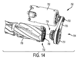
図7〜9を参照すると、旋回可能外部カバー722を有する表面清掃ヘッド700の一実施形態が、より詳細に述べられる。この実施形態において、表面清掃ヘッド700は、攪拌機チャンバ720を含む清掃ヘッドハウジング710、及び、清掃ヘッドハウジング710の前部分712に対してヒンジ723によって結合される旋回可能外部カバー722を含む。旋回可能外部カバー722は、閉鎖位置(図示せず)と開口位置(図示される)との間でヒンジ723によって旋回する。旋回可能外部カバー722が光を含む場合、光のための配線(図示せず)は、ヒンジ723を横切って通過してもよい。この実施形態において、旋回可能外部カバー722は、ハウジング710に対して前方に旋回して、攪拌機チャンバ720を開口する(図9)。開口位置において、攪拌機チャンバ720は、到達可能であり、攪拌機は、図示するように攪拌機チャンバ720から取外されてもよい。表面清掃ヘッド700のこの実施形態は、同様に、取外し不能である回転可能攪拌機と共に使用されてもよく、それにより、旋回可能外部カバー722は、回転可能攪拌機上に収集されたくずを除去するためにだけ開口される。旋回可能外部カバー722は、同様に、カバーが閉鎖位置にあるときに攪拌機チャンバ720を観察するため、中央領域を横切って延びる透明窓724(図8)を含んでもよい。
With reference to FIGS. 7-9, one embodiment of a
封止部材725は、同様に、旋回可能外部カバー722と清掃ヘッドハウジング710との間で、かつ、攪拌機チャンバ720の周囲の周りに配置されてもよい。そのため、取外し可能攪拌機(図示せず)は、封止部材725の内部で攪拌機チャンバ720内に取り付けられてもよい。示す実施形態において、旋回可能外部カバー722は、カバー722の内部周囲の周りに延びる封止部材725を含む。閉鎖位置において、封止部材725は、攪拌機チャンバ720の周囲の周りで清掃ヘッドハウジング710に対して封止する。封止部材725は、空気及び/又はくずが通過することを防止するため、チャンバ720の周囲の周りの圧力が略等しい状態で、カバー722と清掃ヘッドハウジング710との間の境界において略気密の封止部を形成することが可能である。
The sealing
封止部材725は、エラストマー材料又は他の適した封止材料を含んでいてもよく、また、平坦な面又はリブに対する封止を形成することが可能な任意の知られている構成を有してもよい。例えば、リップシール又は端面シールが、旋回可能外部カバー722上で使用されて、カバーが閉鎖位置まで旋回すると、整列及び封止を促進してもよい。他の実施形態において、封止部材725は、清掃ヘッドハウジング710上に設けられてもよい。
The sealing
表面清掃ヘッド700は、同様に、旋回可能外部カバー722を閉鎖位置に留めるラッチ機構を含んでもよい。ラッチ機構は、外部カバー720と清掃ヘッドハウジング710との間の周囲の周りに複数の係合ポイントを提供してもよく、それにより、封止部材725は、チャンバ720の周囲の周りで略等しい圧力で係合する。
The
示す実施形態において、旋回可能外部カバー722は、ヒンジ723から対向する側にラッチ機構770a、770bを含む。ラッチ機構770a、770bは、清掃ヘッドハウジング710上の溝776a、776bに解放可能に係合するフック774a、774bを有する摺動可能アクチュエータ772a、772bを含んでもよい。ラッチ機構770a、770bのそれぞれは、2つのフック774a、774bを含んで、カバー720とハウジング710との間に、間隔を開けて配置された4つの係合ポイントを提供する。
In the illustrated embodiment, the pivotable
摺動可能アクチュエータ772a、772bは、ラッチ済み位置とラッチ解除位置との間で横方向に移動する。摺動可能アクチュエータ772a、772bは、例えば、ばね(図示せず)によってラッチ済み位置内に偏倚されてもよい。摺動可能アクチュエータ772a、772bは、ばね偏倚に抗して摺動可能アクチュエータ772a、772bを移動させるため、ラッチリリース726a、726bに動作可能に結合され、それにより、溝776a、776bからフック774a、774bを解除する(図8において矢印で示す)。他の実施形態において、ラッチ機構770a、770bは清掃ヘッドハウジング110上に配置されてもよく、また、溝776a、776bは外部カバー722上に配置されてもよい。2つのラッチ機構及び4つのフックが示されるが、他の数のラッチ機構及びフックが、同様に使用されてもよい。
The slidable actuators 772a, 772b move laterally between the latched position and the unlatched position. The slidable actuators 772a, 772b may be biased into a latched position by, for example, a spring (not shown). The slidable actuators 772a, 772b are operably coupled to the latch releases 726a, 726b to move the slidable actuators 772a, 772b against spring bias, so that the hooks 774a, 774b is released (indicated by an arrow in FIG. 8). In other embodiments, the latch mechanisms 770a, 770b may be disposed on the cleaning
図10を参照すると、表面清掃ヘッド700のこの実施形態は、駆動機構750によって駆動される取外し可能で回転可能な攪拌機730を受取ってもよい。この実施形態において、駆動機構750は、攪拌機チャンバ720の被駆動側部において回転可能攪拌機730の被駆動端732に軸方向に係合し、回転可能攪拌機730の非被駆動端734は、攪拌機チャンバ720の非被駆動側部で自由に回転するために取り付けられる。取外し可能で回転可能な攪拌機730の被駆動端732及び非被駆動端734は、外部カバー722が開口位置にあるときに攪拌機730が取外されることを可能にする方法で、攪拌機チャンバ720内に取り付けられる。
Referring to FIG. 10, this embodiment of the
この実施形態において、外部カバー722は、取外し可能で回転可能な攪拌機730を攪拌機チャンバ720内に留めるように構成される。外部カバー720は、例えば、取外し可能で回転可能な攪拌機730の非被駆動端734に係合する係合構造728を含む。他の実施形態において、攪拌機係合部材739は、取外し可能で回転可能な攪拌機730の非被駆動端734と係合状態になるよう移動するため、表面清掃ヘッドハウジング710に移動可能に取り付けられてもよい。攪拌機係合部材739は、概略的に示されるが、クリップ、スライド、又は、ラッチの形態であってもよく、また、攪拌機130と係合状態になるよう、また、そこから出るよう、摺動及び/又は旋回してもよい。
In this embodiment, the
この実施形態は、先に示し述べたのと同様の旋回可能外部カバー722を示すが、この実施形態の取外し可能で回転可能な攪拌機730は、同様に、他のタイプの開口可能外部カバーと共に使用されてもよい。
Although this embodiment shows a pivotable
表面清掃ヘッド700は、また、旋回可能外部カバー722が開口位置にあるとき、駆動機構750に対する電力を停止するキルスイッチを含んでもよい。キルスイッチアクチュエータ721は、攪拌機チャンバ720の周囲に沿うポイントに配置されて、旋回可能外部カバー722が開口するとキルスイッチを起動させる。例示的な実施形態において、キルスイッチアクチュエータ721は、キルスイッチをオープンする開口位置まで偏倚される。旋回可能外部カバー722が閉鎖位置にあるとき、カバー722は、キルスイッチアクチュエータ721に係合して、キルスイッチをクローズし、駆動機構750に対する給電を可能にする。旋回可能外部カバー722が開口位置まで移動すると、アクチュエータ721は、偏倚した開口位置まで移動して、キルスイッチをオープンし、駆動機構750に対する給電を停止する。一実施形態において、キルスイッチアクチュエータ721は、ユーザによって作動されることを防止するため窪まされてもよく、また、カバー722から延びる突出部(例えば、小さなロッド)によって作動されてもよい。アクチュエータ721は、また、他の場所にあってもよく、また、他の方法で作動されてもよい。
The
表面清掃ヘッド700のこの実施形態によれば、攪拌機チャンバ720は、また、例えば、上述したように、非被駆動式攪拌機を受取るように構成される。図11及び12に示すように、上述した非被駆動式攪拌機630は、駆動機構750に係合することなく、攪拌機チャンバ720内に配置されてもよい。この実施形態において、攪拌機本体631の端632のウィング631aは、駆動機構750の駆動部材770の下で摺動し、攪拌機630に接触することなく回転するのに十分な隙間を駆動部材770について提供する。攪拌機本体631の底側部分は、攪拌機チャンバ720の下部開口の幅に対応する幅を有する(図11参照)。
According to this embodiment of the
非被駆動式攪拌機630が攪拌機チャンバ720内に配置されると、空気出口638は、表面清掃ヘッド700内の汚れ空気入口743に係合し(図7A、8、及び11参照)、攪拌機本体631の底側部分上の突出部637は、攪拌機チャンバ720の一方の側部に沿う溝713に受取られる(図8及び12参照)。空気出口638の周りの封止部639の弾性によって、突出部637は、溝713に密着して嵌合してもよく、それにより、非被駆動式攪拌機630は、攪拌機チャンバ720内の所定の場所に配置される。そのため、弾性封止部639によって加えられる力は、非被駆動式攪拌機630を所定の場所に保持する。攪拌機チャンバ720内で適切に配置されると、溝713は、摩擦嵌合によって突出部637を受取り、攪拌機本体631の底部上の空間639a、639bは、攪拌機チャンバ720の下部開口を横切って延びる底部ガード又はバー711a、711bを受取り、清掃パッド(複数可)635a〜635cは、攪拌機チャンバ720の下部開口を通して延びる(図12参照)。
When the
図13及び14により詳細に示すように、駆動機構750は、モータ752、回転伝達機構754、及び、スプライン付き駆動部材770を含む。この実施形態において、回転伝達機構754は、モータ752の出力に結合する駆動ホイール753に摩擦係合し、スプライン付き駆動部材770に結合される被駆動ホイール755に摩擦係合するベルト755を含む。駆動機構750は、攪拌機730を、700±100RPMの低速、及び、3500±500RPMの高速で回転することが可能であってもよい。他の実施形態において、限定はしないが、歯車列、又は、モータとスプライン付き駆動部材との間の直接駆動結合を含む他の回転伝達機構が使用されてもよい。他の実施形態において、モータは、内部に回転可能攪拌機内に配置されてもよい。更なる実施形態において、駆動機構は、限定はしないが、空気駆動式タービンを含む、回転可能攪拌機に回転を与えることが可能な他の機構を含んでもよい。
As shown in more detail in FIGS. 13 and 14, the
図15により詳細に示すように、取外し可能で回転可能な攪拌機730の被駆動端732は、スプライン付き駆動部材770に軸方向に嵌合するように構成されるスプライン付き被駆動部材780を含む。そのため、スプライン付き駆動部材770及びスプライン付き被駆動部材780は、ベルトを使用することなく、回転及びトルクを伝達するスプライン結合又ジョイントを形成する。スプライン付き駆動部材770及びスプライン付き被駆動部材780は、攪拌機の回転軸に対して半径方向に向けられたスプライン歯772、782を有する。スプライン歯772、782は、スプライン歯772、782の間で対応する形状及び空間778、788を有し、それにより、スプライン歯772、782は、図16に示すように、部材770、780が軸方向に係合するとかみ合う。
As shown in more detail in FIG. 15, the
示す実施形態は、外部スプラインを有するスプライン付き駆動部材770、及び、内部スプラインを有するスプライン付き被駆動部材780を示す。他の実施形態において、スプライン付き駆動部材770は内部スプラインを含んでもよく、スプライン付き被駆動部材780は外部スプラインを含んでもよい。
The illustrated embodiment shows a
示す実施形態において、スプライン付き駆動部材770及びスプライン付き被駆動部材780上のスプライン歯772、782は共に、略ウェッジ状であり、半径方向に外側の部分771、781は、半径方向に内側の部分773、783より広い(図16参照)。スプライン歯772、782は、また、スプライン歯772、782の半径方向面776、786から外方にテーパが付いているテーパ状側壁774、775、784、785を有する。図17に示すように、スプライン付き被駆動部材780上のスプライン歯782は、また、テーパ状又は面取りされた半径方向面786を有し、その半径方向面786は、内方に(すなわち、攪拌機の非被駆動端に向かって)テーパが付き、約30°〜60°の範囲で、半径方向ライン708に対して鋭角を形成する。スプライン付き駆動部材770上のスプライン歯772は、回転軸に向かって内方にテーパが付いているテーパ状又は面取りされた軸方向面777を有してもよい。
In the illustrated embodiment, the
示す実施形態におけるスプライン歯772、782の形状及び構成は、自己整列を提供し、スプライン付き被駆動部材780とスプライン付き駆動部材770との係合を促進する。スプライン付き駆動部材770及びスプライン付き被駆動部材780は、幾つかの異なる角度位置で係合し得、したがって、係合のために正確な角度整列を必要としない。示す実施形態におけるスプライン歯772、782の形状及び構成は、また、スプライン付き駆動部材770がスプライン付き被駆動部材780を駆動するときのバックラッシュを減少、又は、なくし得る。
The shape and configuration of the
スプライン付き被駆動部材780及びスプライン付き駆動部材770の一方又は両方は、また、より高い(例えば、90以上の)デュロメーター硬度を有する熱可塑性ゴム等のエラストマー材料を含んでいても良い。エラストマー材料は、スプライン歯772、782の係合を促進してもよく、また、スプライン付き駆動部材770がスプライン付き被駆動部材780を駆動するときの振動減少又は分離を提供してもよい。そのため、駆動機構750は、振動が減少した状態でより高いRPMで攪拌機730を回転させ得る。
One or both of splined driven
示す実施形態において、スプライン付き駆動部材770及びスプライン付き被駆動部材780のそれぞれは、回転軸の周りにスター構成で配列される六つ(6)のスプライン歯772、782を有する。6つのスプライン歯は、また、整列を促進しバックラッシュを防止しながら、所望の駆動力及びトルクに耐えることが可能である。しかしながら、スプライン歯の数は、他の数でも良い。スプライン付き駆動部材770及びスプライン付き被駆動部材780上のスプライン歯の他の形状及び構成もまた、可能であってもよい。更に、限定はしないが、ドッグクラッチ、滑り止め付クラッチ、ヒルト(Hirth)ジョイント、及び、カービック結合を含む、トルク及び回転を伝達するため回転シャフトを軸方向に結合するための他の結合又は機構もまた、使用されてもよい。
In the embodiment shown, each of the
図18により詳細に示すように、取外し可能で回転可能な攪拌機730のこの実施形態の非被駆動端734は、アクスル791上に回転可能に取り付けられるブッシング792に留められるエンドキャップ790を含む。アクスル791は、攪拌機本体731内に固定され、そこから延びる。エンドキャップ790は、攪拌機チャンバ720内で支持され、ブッシング792を留めるように構成され、それにより、アクスル791はブッシング792内で回転し、回転可能攪拌機730はその回転軸の周りに回転する。この実施形態において、エンドキャップ790は、摩擦嵌合によってブッシング792に取外し可能に留められるが、エンドキャップ790はまた、ブッシング792に固定されてもよい。他の実施形態において、ブッシング792は、エンドキャップなしで攪拌機チャンバ720内に直接取り付けられるように構成されてもよい。種々の他の構成も、攪拌機チャンバ720内で回転可能攪拌機730の非被駆動端734を回転可能に支持するために使用されてもよい。
As shown in more detail in FIG. 18, the
図19及び20により詳細に示すように、エンドキャップ790は、攪拌機730の非被駆動端734を攪拌機チャンバ720から取外すために容易に掴めるように形成されるタブ796を含む。エンドキャップ790はまた、ブッシング792が静止して保持されるよう、エンドキャップ790が回転することを防止するため、攪拌機チャンバ内の嵌合構造に係合する1つ又は複数の安定化構造793、795、797を含み、それにより、回転可能攪拌機が被駆動端732で駆動されると、アクスル791がブッシング792内で自由に回転することを可能にする。エンドキャップ790のこの実施形態はまた、カバーが閉鎖して、攪拌機730を攪拌機チャンバ720内に留めると、外部カバー722上の係合構造728に係合するエラストマーパッド799を含む。エンドキャップ790は、ブッシング792に摩擦係合するエラストマーリング798を更に含む。エラストマーパッド799及びエラストマーリング798は、有利には、攪拌機730が攪拌機チャンバ720内で回転しているときに振動を防止又は分離してもよく、また、共に、同じゴム材料から成形されてもよい。エンドキャップ790は、攪拌機本体731の端表面736に接触するワッシャ794(例えば、フェルトワッシャ)を更に含んで、ごみが軸受792から離れたままにしてもよい。
As shown in more detail in FIGS. 19 and 20, the
図21〜23を参照すると、エンドキャップ790と攪拌機チャンバ720との係合がより詳細に述べられる。非被駆動側部において、チャンバ720は、チャンバ720は、エンドキャップ790の端部分を受取る窪んだ領域729を定める取付レール727a、727bを含む。そのため、エンドキャップ790の端部分は、図22に示すように、取付レール727a、727bの間で摺動してもよい。図23に示すように、安定化構造793、795、797は、取付レール727a、727b上の対応する構造に係合し、カバー722の内部の係合構造728は、エラストマーパッド799に係合する。そのため、エンドキャップ790及びブッシング792は、攪拌機730が回転すると静止したままである。付加的に又は代替的に、カバー722は、エンドキャップ790の他の部分(例えば、タブ796)に係合して、エンドキャップ790をチャンバ720内に保持してもよい。この実施形態において、安定化構造793、795、797は、特定の向きで取付レール727a、727bに嵌合するように設計又は固定される特定の構成を有し(図23参照)、それにより、エンドキャップ790は、カバー722によって係合されるように適切に配置される。
Referring to FIGS. 21-23, the engagement of the
攪拌機チャンバ720内に回転可能攪拌機730を取り付けるため、被駆動端732は、チャンバ720の中に向けて角度を付けられて、スプライン付き駆動部材770をスプライン付き被駆動部材780に係合させる(図16参照)。エンドキャップ790は、その後、エンドキャップ790が取付レール727a、727bの間に嵌合するまで、攪拌機730の非被駆動端734をチャンバ720内に下げるために使用されてもよい。攪拌機730がチャンバ720内に適切に配置されると、外部カバー722は、その後、閉鎖して、チャンバ720を覆い、回転可能攪拌機730をチャンバ720内に留めてもよい。回転可能攪拌機730を取外すため、ユーザは、タブ796を掴んで、取付レール727a、727bの間から出るようエンドキャップ790を摺動させ、それによって、非被駆動端734をチャンバ720から出るよう持上げてもよい。ユーザは、その後、スプライン付き駆動部材770及びスプライン付き被駆動部材780が脱離するまで、攪拌機730を持上げ続けてもよい。ユーザは、その後、攪拌機730を清掃してもよいし、かつ/又は、別のタイプの攪拌機を挿入してもよい。
To mount the
図24を参照すると、スティック負圧掃除機の表面清掃ヘッド2400は、外部カバー2422によって覆われ、取外し可能攪拌機を収容する開口可能攪拌機チャンバを含んでもよい。外部カバー2422、開口可能チャンバ、及び、表面清掃ヘッド2400内に配置される取外し可能攪拌機は、本明細書で述べる実施形態のうちの任意の実施形態で実装されてもよい。
Referring to FIG. 24, the
図25を参照すると、直立負圧掃除機の表面清掃ヘッド2500は、外部カバー2522によって覆われ、取外し可能攪拌機を収容する開口可能攪拌機チャンバを含んでもよい。外部カバー2522、開口可能チャンバ、及び、表面清掃ヘッド2500内に配置される取外し可能攪拌機は、本明細書で述べる実施形態のうちの任意の実施形態で実装されてもよい。
Referring to FIG. 25, a
移動可能外部カバーはまた、例えば図26〜29に示すように他の構成を有してもよい。図26は、清掃ヘッドハウジング2610に対して後方に開口位置まで旋回する旋回可能外部カバー2622を有する表面清掃ヘッド2600の別の実施形態を示す。図27は、前方に旋回する1つのカバー部分2722a、及び、清掃ヘッドハウジング2710に対して後方に旋回する別のカバー部分2722bを含む複数ピース旋回可能外部カバーを有する表面清掃ヘッド2700の更なる実施形態を示す。図28は、例えば、ガレージ扉と同様の、清掃ヘッドハウジング2810に対して縦方向に摺動又は転動する摺動可能外部カバー2822を有する表面清掃ヘッド2800の更に別の実施形態を示す。図29は、清掃ヘッドハウジング2910に対して側方に摺動する摺動可能外部カバー2922を有する表面清掃ヘッド2900の更なる実施形態を示す。
The movable outer cover may also have other configurations, for example as shown in FIGS. FIG. 26 illustrates another embodiment of a
これらの実施形態の任意の実施形態において、外部カバーは、例えば、上述したラッチ機構又は任意の他のラッチ機構を使用して掛けられてもよい。これらの実施形態の任意の実施形態において、外部カバーは、例えば、上述した封止部材又は任意の他の封止部材を使用して封止されてもよい。これらの実施形態のそれぞれにおいて、外部カバーは、表面清掃ヘッドハウジングに係合したままである間に、開口位置と閉鎖位置との間で移動してもよい。他の実施形態において、外部カバーは、表面清掃ヘッドハウジングから完全に取外されてもよい。外部カバーについての他の変形及び場所もまた、本開示の範囲内にある。 In any of these embodiments, the outer cover may be hung using, for example, the latch mechanism described above or any other latch mechanism. In any of these embodiments, the outer cover may be sealed using, for example, the sealing members described above or any other sealing member. In each of these embodiments, the outer cover may move between an open position and a closed position while remaining engaged with the surface cleaning head housing. In other embodiments, the outer cover may be completely removed from the surface cleaning head housing. Other variations and locations for the outer cover are also within the scope of this disclosure.
したがって、本開示の実施形態と矛盾しない表面清掃ヘッドは、表面清掃ヘッド内での攪拌機の検査、清掃、サービス、及び/又は、交換を促進するために開口可能攪拌機チャンバを含む。取外し可能攪拌機は、攪拌機チャンバ内で駆動機構に係合する回転可能な被駆動式攪拌機、又は、駆動機構に係合することなく攪拌機内に受取られる回転不能非被駆動式攪拌機を含んでもよい。 Accordingly, a surface cleaning head consistent with embodiments of the present disclosure includes an openable agitator chamber to facilitate agitator inspection, cleaning, service, and / or replacement within the surface cleaning head. The removable agitator may include a rotatable driven agitator that engages the drive mechanism within the agitator chamber, or a non-rotatable non-driven agitator that is received in the agitator without engaging the drive mechanism.
本発明の原理が本明細書で述べられたが、本説明が、本発明の範囲に対する制限としてではなく、単に例として行われることが当業者によって理解される。他の実施形態は、本明細書で示し述べる例示的な実施形態に加えて、本発明の範囲内にあると考えられる。表面清掃装置が本明細書に含まれる特徴の任意の1つ又は複数を具現化してもよいこと、及び、その特徴が任意の特定の組合せ又は部分的組合せで使用されてもよいことが当業者によって認識されるであろう。当業者による修正及び代用は、添付特許請求の範囲による場合を除いて制限されない本発明の範囲内にあると考えられる。 Although the principles of the present invention have been set forth herein, it will be understood by those skilled in the art that the present description is made merely by way of example and not as a limitation on the scope of the invention. Other embodiments are considered to be within the scope of the present invention in addition to the exemplary embodiments shown and described herein. Those skilled in the art that a surface cleaning device may embody any one or more of the features included herein, and that the features may be used in any particular combination or subcombination. Will be recognized by. Modifications and substitutions by those skilled in the art are considered to be within the scope of the invention, which is not limited except as by the appended claims.
Claims (119)
前端部分、後端部分、側方に配置される側部、上側部分、及び、底側部分を有する清掃ヘッドハウジングと、
前記清掃ヘッドハウジングの前記前端部分内に配置される攪拌機チャンバであって、前記清掃ヘッドハウジングの前記上側部分を通る上部開口、及び、前記清掃ヘッドハウジングの前記底側部分を通る下部開口を有する、攪拌機チャンバと、
前記攪拌機チャンバの前記上部開口を覆うため、前記清掃ヘッドハウジングに旋回可能に取り付けられる外部カバーであって、閉鎖位置と開口位置との間で旋回可能であり、前記攪拌機チャンバは、前記外部カバーが前記閉鎖位置にあるときに覆われ、前記外部カバーが前記開口位置にあるときに前記上部開口を通して到達可能である、外部カバーと、
前記攪拌機チャンバ内に取外し可能に取り付けられる回転可能な被駆動式攪拌機であって、それにより、前記攪拌機は、前記下部開口を通して表面に接触するように構成され、前記上部開口を通して取外されるように構成される、回転可能な被駆動式攪拌機とを備え、前記回転可能な被駆動式攪拌機は、被駆動端及び非被駆動端を含み、前記外部カバーは、前記攪拌機を前記攪拌機チャンバ内に保持するため前記閉鎖位置で前記攪拌機の前記非被駆動端に係合し、前記外部カバーは、前記開口位置まで移動すると、前記攪拌機の前記非被駆動端から脱離し、前記攪拌機は、前記外部カバーが前記開口位置にあるとき、前記上部開口を通して到達可能でかつ取外し可能である、表面清掃ヘッド。 A surface cleaning head for negative pressure,
A cleaning head housing having a front end portion, a rear end portion, a laterally disposed side portion, an upper portion, and a bottom portion;
An agitator chamber disposed within the front end portion of the cleaning head housing, having an upper opening through the upper portion of the cleaning head housing and a lower opening through the bottom portion of the cleaning head housing; An agitator chamber;
An outer cover pivotably attached to the cleaning head housing to cover the upper opening of the stirrer chamber, wherein the outer cover is pivotable between a closed position and an open position; An outer cover that is covered when in the closed position and is reachable through the upper opening when the outer cover is in the open position;
A rotatable driven agitator removably mounted within the agitator chamber so that the agitator is configured to contact a surface through the lower opening and is removed through the upper opening. A rotatable driven stirrer configured, wherein the rotatable driven stirrer includes a driven end and a non-driven end, and the outer cover places the stirrer in the stirrer chamber Engage with the non-driven end of the stirrer in the closed position to hold, the outer cover is detached from the non-driven end of the stirrer when moved to the open position, and the stirrer A surface cleaning head that is reachable and removable through the top opening when a cover is in the open position.
前記空気流路に沿って移動する空気を輸送し処理するための空気輸送及び処理システムとを更に備える、請求項1に記載の表面清掃ヘッド。 An air flow path extending from the dirty air inlet to the clean air outlet;
The surface cleaning head of claim 1, further comprising an air transport and processing system for transporting and processing air moving along the air flow path.
前端部分、後端部分、側方に配置される側部、上側部分、及び、底側部分を有する清掃ヘッドハウジングと、
前記清掃ヘッドハウジングの前記前端部分内に配置される攪拌機チャンバであって、前記清掃ヘッドハウジングの前記上側部分を通る上部開口、及び、前記清掃ヘッドハウジングの前記底側部分を通る下部開口を有する、攪拌機チャンバと、
前記攪拌機チャンバの前記上部開口を覆うため、前記清掃ヘッドハウジングに旋回可能に取り付けられる外部カバーであって、閉鎖位置と開口位置との間で移動可能であり、前記攪拌機チャンバは、前記外部カバーが前記閉鎖位置にあるときに覆われ、前記外部カバーが前記開口位置にあるときに前記上部開口を通して到達可能である、外部カバーと、
前記攪拌機チャンバの周りで前記清掃ヘッドハウジングと前記外部カバーとの間の境界を封止するため、前記攪拌機チャンバの周りの、前記外部カバーの内側部分及び前記清掃ヘッドハウジングの内側部分の少なくとも一方の周囲の周りの封止部材と、
前記外部カバーを前記閉鎖位置に保持するため、前記外部カバーと前記清掃ヘッドハウジングとの間の前記周囲の周りに複数の係合ポイントを設けるように構成されるラッチ機構と、
前記攪拌機チャンバ内に取り付けられる回転可能な被駆動式攪拌機であって、それにより、前記攪拌機は、前記下部開口を通して表面に接触するように構成される、回転可能な被駆動式攪拌機とを備え、前記回転可能な被駆動式攪拌機は被駆動端及び非被駆動端を含み、前記攪拌機は、前記外部カバーが前記開口位置にあるとき、前記上部開口を通して到達可能である、表面清掃ヘッド。 A surface cleaning head for negative pressure,
A cleaning head housing having a front end portion, a rear end portion, a laterally disposed side portion, an upper portion, and a bottom portion;
An agitator chamber disposed within the front end portion of the cleaning head housing, having an upper opening through the upper portion of the cleaning head housing and a lower opening through the bottom portion of the cleaning head housing; An agitator chamber;
An outer cover pivotably attached to the cleaning head housing to cover the upper opening of the stirrer chamber, the outer cover being movable between a closed position and an open position; An outer cover that is covered when in the closed position and is reachable through the upper opening when the outer cover is in the open position;
At least one of an inner portion of the outer cover and an inner portion of the cleaning head housing around the agitator chamber to seal a boundary between the cleaning head housing and the outer cover around the agitator chamber. A sealing member around the periphery;
A latch mechanism configured to provide a plurality of engagement points around the periphery between the outer cover and the cleaning head housing to hold the outer cover in the closed position;
A rotatable driven agitator mounted in the agitator chamber, whereby the agitator comprises a rotatable driven agitator configured to contact a surface through the lower opening; A surface cleaning head, wherein the rotatable driven agitator includes a driven end and a non-driven end, and the agitator is reachable through the upper opening when the outer cover is in the open position.
前端部分、後端部分、側方に配置される側部、上側部分、及び、底側部分を有する清掃ヘッドハウジングと、
前記清掃ヘッドハウジングの前記前端部分内に配置される攪拌機チャンバであって、前記清掃ヘッドハウジングの前記上側部分を通る上部開口、及び、前記清掃ヘッドハウジングの前記底側部分を通る下部開口を有し、非被駆動側部及び被駆動側部を含む、攪拌機チャンバと、
前記攪拌機チャンバの前記被駆動側部における駆動部材、及び、前記駆動部材に駆動結合される攪拌機駆動モータを含む攪拌機駆動機構と、
前記攪拌機チャンバの前記上部開口を覆うため、前記清掃ヘッドハウジングに取り付けられる外部カバーであって、閉鎖位置と開口位置との間で移動可能であり、前記攪拌機チャンバは、前記外部カバーが前記閉鎖位置にあるときに覆われ、前記外部カバーが前記開口位置にあるときに前記上部開口を通して到達可能である、外部カバーと、
前記攪拌機チャンバ内に取外し可能に取り付けられる回転可能な被駆動式攪拌機であって、それにより、前記攪拌機は、前記下部開口を通して表面に接触するように構成される、回転可能な被駆動式攪拌機とを備え、前記攪拌機は、前記外部カバーが前記開口位置にあるとき、前記上部開口を通して到達可能でありかつ取外し可能であり、前記回転可能な被駆動式攪拌機は、前記攪拌機チャンバの前記非被駆動側部に取り付けられる非被駆動端を含み、それにより、前記攪拌機は、前記非被駆動端及び被駆動部材を含む被駆動端で自由に回転し、前記被駆動部材は、前記駆動機構の前記駆動部材に軸方向に嵌合すると共に係合し、それにより、前記駆動部材は、トルク及び回転を前記被駆動部材及び前記回転可能な被駆動式攪拌機に伝達する、表面清掃ヘッド。 A surface cleaning head for negative pressure,
A cleaning head housing having a front end portion, a rear end portion, a laterally disposed side portion, an upper portion, and a bottom portion;
A stirrer chamber disposed within the front end portion of the cleaning head housing, having an upper opening through the upper portion of the cleaning head housing and a lower opening through the bottom portion of the cleaning head housing. A stirrer chamber comprising a non-driven side and a driven side;
A stirrer drive mechanism including a drive member in the driven side portion of the stirrer chamber, and a stirrer drive motor drivingly coupled to the drive member;
An outer cover attached to the cleaning head housing to cover the upper opening of the agitator chamber, the outer cover being movable between a closed position and an open position, wherein the agitator chamber has the outer cover in the closed position; An outer cover that is covered when the outer cover is in the open position and is reachable through the upper opening when the outer cover is in the open position;
A rotatable driven agitator removably mounted in the agitator chamber, whereby the agitator is configured to contact a surface through the lower opening; and The stirrer is reachable and removable through the top opening when the outer cover is in the open position, and the rotatable driven stirrer is the undriven of the stirrer chamber Including a non-driven end attached to a side, whereby the agitator is free to rotate at a driven end including the non-driven end and a driven member, the driven member being The drive member is axially fitted and engaged so that the drive member transmits torque and rotation to the driven member and the rotatable driven agitator. Surface cleaning head.
前端部分、後端部分、側方に配置される側部、上側部分、及び、底側部分を有する清掃ヘッドハウジングと、
前記清掃ヘッドハウジングの前記前端部分内に配置される攪拌機チャンバであって、前記清掃ヘッドハウジングの前記上側部分を通る上部開口、及び、前記清掃ヘッドハウジングの前記底側部分を通る下部開口を有する、攪拌機チャンバと、
前記攪拌機チャンバの前記上部開口を覆うため前記清掃ヘッドハウジングに取り付けられる外部カバーであって、閉鎖位置と開口位置との間で移動可能であり、前記攪拌機チャンバは、前記外部カバーが前記閉鎖位置にあるときに覆われ、前記外部カバーが前記開口位置にあるときに前記上部開口を通して到達可能である、外部カバーと、
少なくとも第1及び第2の回転可能な被駆動式攪拌機とを備え、前記回転可能な被駆動式攪拌機のそれぞれは、前記攪拌機チャンバ内に取外し可能に取り付けられ、前記外部カバーが前記開口位置にあるときに前記上部開口を通して取外されるように構成され、それにより、前記回転可能な被駆動式攪拌機は相互交換可能であり、前記第1の回転可能な被駆動式攪拌機は、前記第2の回転可能な被駆動式攪拌機と異なる撹拌特性を有する、表面清掃ヘッド。 A surface cleaning head for negative pressure,
A cleaning head housing having a front end portion, a rear end portion, a laterally disposed side portion, an upper portion, and a bottom portion;
An agitator chamber disposed within the front end portion of the cleaning head housing, having an upper opening through the upper portion of the cleaning head housing and a lower opening through the bottom portion of the cleaning head housing; An agitator chamber;
An outer cover attached to the cleaning head housing to cover the upper opening of the agitator chamber, the outer cover being movable between a closed position and an open position, wherein the agitator chamber has the outer cover in the closed position; An outer cover that is covered at a time and is reachable through the upper opening when the outer cover is in the open position;
At least first and second rotatable driven agitators, each of the rotatable driven agitators being removably mounted within the agitator chamber, and the outer cover being in the open position Sometimes configured to be removed through the top opening, whereby the rotatable driven agitator is interchangeable, and the first rotatable driven agitator is the second rotatable agitator. A surface cleaning head having different stirring characteristics than a rotatable driven stirrer.
前記攪拌機チャンバの前記被駆動側部における駆動部材、及び、前記駆動部材に駆動結合される攪拌機駆動モータを含む攪拌機駆動機構を更に備える、請求項42に記載の表面清掃ヘッド。 The agitator chamber includes a non-driven side portion and a driven side portion;
43. The surface cleaning head according to claim 42, further comprising a stirrer drive mechanism including a drive member in the driven side portion of the stirrer chamber and a stirrer drive motor drivingly coupled to the drive member.
前端部分、後端部分、側方に配置される側部、上側部分、及び、底側部分を有する清掃ヘッドハウジングと、
前記清掃ヘッドハウジングの前記前端部分内に配置される攪拌機チャンバであって、前記清掃ヘッドハウジングの前記上側部分を通る上部開口、及び、前記清掃ヘッドハウジングの前記底側部分を通る下部開口を有し、回転可能な被駆動式攪拌機を、前記攪拌機が前記下部開口を通して表面に接触し上部開口を通して取外し可能であるように受取るように構成され、前記回転可能な被駆動式攪拌機の非被駆動端を受取るための非被駆動側部、及び、前記回転可能な被駆動式攪拌機の被駆動端を受取るための被駆動側部を含む、攪拌機チャンバと、
前記攪拌機チャンバの前記被駆動側部における駆動部材、及び、前記駆動部材に駆動結合される攪拌機駆動モータを含む攪拌機駆動機構であって、前記駆動部材は、前記回転可能な被駆動式攪拌機上で前記被駆動部材に軸方向に嵌合すると共に係合するよう構成され、それにより、前記駆動部材は、トルク及び回転を前記被駆動部材及び前記回転可能な被駆動式攪拌機に伝達する、攪拌機駆動機構と、
前記攪拌機チャンバの前記上部開口を覆うため前記清掃ヘッドハウジングに取り付けられる外部カバーとを備え、前記外部カバーは、閉鎖位置と開口位置との間で移動可能であり、前記攪拌機チャンバは、前記外部カバーが前記閉鎖位置にあるときに覆われ、前記外部カバーが前記開口位置にあるときに、前記上部開口を通して到達可能である、表面清掃ヘッド。 A surface cleaning head for negative pressure,
A cleaning head housing having a front end portion, a rear end portion, a laterally disposed side portion, an upper portion, and a bottom portion;
A stirrer chamber disposed within the front end portion of the cleaning head housing, having an upper opening through the upper portion of the cleaning head housing and a lower opening through the bottom portion of the cleaning head housing. A rotatable driven agitator configured to receive the agitator such that the agitator contacts the surface through the lower opening and is removable through the upper opening, the undriven end of the rotatable driven agitator being A stirrer chamber including a non-driven side for receiving and a driven side for receiving a driven end of the rotatable driven stirrer;
A stirrer drive mechanism including a drive member in the driven side portion of the stirrer chamber and a stirrer drive motor drivingly coupled to the drive member, wherein the drive member is on the rotatable driven stirrer Agitator drive configured to engage and engage the driven member in an axial direction so that the drive member transmits torque and rotation to the driven member and the rotatable driven agitator Mechanism,
An outer cover attached to the cleaning head housing to cover the upper opening of the stirrer chamber, the outer cover being movable between a closed position and an open position, the stirrer chamber comprising the outer cover A surface cleaning head that is covered when in the closed position and is reachable through the top opening when the outer cover is in the open position.
被駆動端及び非被駆動端を有する攪拌機本体と、
前記被駆動端と前記非被駆動端との間で、前記攪拌機本体の少なくとも一部分上に配置される少なくとも1つの撹拌要素と、
前記攪拌機本体の前記被駆動端に配置される被駆動部材であって、前記表面清掃ヘッド内の駆動機構上の駆動部材に軸方向に嵌合すると共に係合するように構成される、被駆動部材と、
前記攪拌機本体の前記非被駆動端から延びるアクスルと、
前記アクスル上に回転可能に取り付けられるブッシングと、
前記ブッシング上に取り付けられ、前記表面清掃ヘッドの攪拌機チャンバ内に回転することなく取り付けられるように構成されるエンドキャップとを備える、取外し可能で回転可能な攪拌機組立体。 A removable and rotatable agitator assembly for use in a negative pressure surface cleaning head comprising:
An agitator body having a driven end and a non-driven end;
At least one agitation element disposed on at least a portion of the agitator body between the driven end and the non-driven end;
A driven member disposed at the driven end of the stirrer body, the driven member configured to be fitted and engaged with a driving member on a driving mechanism in the surface cleaning head in an axial direction. A member,
An axle extending from the non-driven end of the agitator body;
A bushing rotatably mounted on the axle;
A removable and rotatable agitator assembly comprising an end cap mounted on the bushing and configured to be mounted in the agitator chamber of the surface cleaning head without rotation.
被駆動端及び非被駆動端を有する攪拌機本体と、
前記被駆動端と前記非被駆動端との間で、前記攪拌機本体の少なくとも一部分上に配置される少なくとも1つの撹拌要素と、
前記攪拌機本体の前記被駆動端に配置される被駆動部材であって、前記表面清掃ヘッド内の駆動機構上の駆動部材に軸方向に嵌合すると共に係合するように構成される、被駆動部材と、
前記攪拌機本体の前記被駆動端に配置されるスプライン付き被駆動部材であって、前記表面清掃ヘッド内の駆動機構上のスプライン付き駆動部材に軸方向に嵌合すると共に係合するように構成される、スプライン付き被駆動部材とを備える、取外し可能で回転可能な攪拌機組立体。 A removable and rotatable agitator assembly for use in a negative pressure surface cleaning head comprising:
An agitator body having a driven end and a non-driven end;
At least one agitation element disposed on at least a portion of the agitator body between the driven end and the non-driven end;
A driven member disposed at the driven end of the stirrer body, the driven member configured to be fitted and engaged with a driving member on a driving mechanism in the surface cleaning head in an axial direction. A member,
A splined driven member disposed at the driven end of the agitator body, the splined driven member on the driving mechanism in the surface cleaning head is configured to be fitted and engaged in the axial direction. A removable stirrer assembly comprising a splined driven member.
前記アクスルに回転可能に取り付けられるブッシングと、
前記ブッシング上に取り付けられ、前記表面清掃ヘッドの攪拌機チャンバ内に回転することなく取り付けられるように構成されるエンドキャップとを更に備える、請求項87に記載の取外し可能で回転可能な攪拌機。 An axle extending from the non-driven end of the agitator body;
A bushing rotatably mounted on the axle;
90. The removable rotatable agitator of claim 87 further comprising an end cap mounted on the bushing and configured to be mounted without rotation in the agitator chamber of the surface cleaning head.
前端部分、後端部分、側方に配置される側部、上側部分、及び、底側部分を有する清掃ヘッドハウジングと、
前記清掃ヘッドハウジングの前記前端部分内に配置される攪拌機チャンバであって、前記清掃ヘッドハウジングの前記上側部分を通る上部開口、及び、前記清掃ヘッドハウジングの前記底側部分を通る下部開口を有し、少なくとも1つの被駆動側部を含む、攪拌機チャンバと、
前記攪拌機チャンバの前記被駆動側部における駆動部材、及び、前記駆動部材に駆動結合される攪拌機駆動モータを含む攪拌機駆動機構であって、前記駆動部材は、前記攪拌機チャンバ内に受取られると、回転可能な被駆動式攪拌機に係合し、回転可能な被駆動式攪拌機を駆動するように構成される、攪拌機駆動機構と、
前記攪拌機チャンバの前記上部開口を覆うため、前記清掃ヘッドハウジングに取り付けられる外部カバーであって、閉鎖位置と開口位置との間で移動可能であり、前記攪拌機チャンバは、前記外部カバーが前記閉鎖位置にあるときに覆われ、前記外部カバーが前記開口位置にあるときに前記上部開口を通して到達可能である、外部カバーと、
前記駆動部材に係合することなく、前記攪拌機チャンバ内に取外し可能に取り付けられる非被駆動式攪拌機であって、それにより、非被駆動式攪拌機は、前記下部開口を通して表面に接触するように構成される、非被駆動式攪拌機とを備え、前記非被駆動式攪拌機は、前記外部カバーが前記開口位置にあるとき、前記上部開口を通して到達可能でありかつ取外し可能である、表面清掃ヘッド。 A surface cleaning head for negative pressure,
A cleaning head housing having a front end portion, a rear end portion, a laterally disposed side portion, an upper portion, and a bottom portion;
A stirrer chamber disposed within the front end portion of the cleaning head housing, having an upper opening through the upper portion of the cleaning head housing and a lower opening through the bottom portion of the cleaning head housing. A stirrer chamber comprising at least one driven side;
A stirrer drive mechanism including a drive member in the driven side portion of the stirrer chamber and a stirrer drive motor drivingly coupled to the drive member, wherein the drive member rotates when received in the stirrer chamber A stirrer drive mechanism configured to engage a rotatable driven stirrer and to drive a rotatable driven stirrer;
An outer cover attached to the cleaning head housing to cover the upper opening of the agitator chamber, the outer cover being movable between a closed position and an open position, wherein the agitator chamber has the outer cover in the closed position; An outer cover that is covered when the outer cover is in the open position and is reachable through the upper opening when the outer cover is in the open position;
A non-driven agitator that is removably mounted in the agitator chamber without engaging the drive member, whereby the non-driven agitator is configured to contact the surface through the lower opening A non-driven stirrer, wherein the non-driven stirrer is reachable and removable through the top opening when the outer cover is in the open position.
前端部分、後端部分、側方に配置される側部、上側部分、及び、底側部分を有する清掃ヘッドハウジングと、
前記清掃ヘッドハウジングの前記前端部分内に配置される攪拌機チャンバであって、前記清掃ヘッドハウジングの前記上側部分を通る上部開口、及び、前記清掃ヘッドハウジングの前記底側部分を通る下部開口を有し、少なくとも1つの被駆動側部を含む、攪拌機チャンバと、
前記攪拌機チャンバの前記被駆動側部における駆動部材、及び、前記駆動部材に駆動結合される攪拌機駆動モータを含む攪拌機駆動機構と、
少なくとも1つの回転可能な被駆動式攪拌機であって、前記攪拌機チャンバ内に取外し可能に取り付けられるように構成され、前記攪拌機駆動機構の前記駆動部材に係合するように構成され、それにより、前記駆動部材は、前記回転可能な被駆動式攪拌機を回転させる、少なくとも1つの回転可能な被駆動式攪拌機と、
前記駆動部材に係合することなく、前記攪拌機チャンバ内に取外し可能に取り付けられるように構成される少なくとも1つの非被駆動式攪拌機であって、それにより、非被駆動式攪拌機は、下部開口を通して表面に接触するように構成される、少なくとも1つの非被駆動式攪拌機とを備える、表面清掃ヘッド。 A surface cleaning head for negative pressure,
A cleaning head housing having a front end portion, a rear end portion, a laterally disposed side portion, an upper portion, and a bottom portion;
A stirrer chamber disposed within the front end portion of the cleaning head housing, having an upper opening through the upper portion of the cleaning head housing and a lower opening through the bottom portion of the cleaning head housing. A stirrer chamber comprising at least one driven side;
A stirrer drive mechanism including a drive member in the driven side portion of the stirrer chamber, and a stirrer drive motor drivingly coupled to the drive member;
At least one rotatable driven stirrer configured to be removably mounted in the stirrer chamber and configured to engage the drive member of the stirrer drive mechanism, thereby The drive member rotates at least one rotatable driven agitator; and at least one rotatable driven agitator;
At least one undriven stirrer configured to be removably mounted in the stirrer chamber without engaging the drive member, whereby the undriven stirrer passes through the lower opening; A surface cleaning head comprising at least one undriven stirrer configured to contact the surface.
被駆動端及び非被駆動端を有する攪拌機本体と、
前記被駆動端と前記非被駆動端との間で前記攪拌機本体の少なくとも一部分上に配置される少なくとも1つの撹拌要素と、
前記攪拌機本体の前記被駆動端に配置される被駆動部材であって、前記表面清掃ヘッド内の駆動機構上の駆動部材に軸方向に嵌合すると共に係合するように構成される、被駆動部材と、
前記攪拌機本体の前記非被駆動端上に取り付けられ、表面清掃ヘッドの前記攪拌機チャンバ内で回転することなく取り付けられるように構成されるエンドキャップとを備える、請求項102に記載の表面清掃ヘッド。 The rotatable driven stirrer is
An agitator body having a driven end and a non-driven end;
At least one agitation element disposed on at least a portion of the agitator body between the driven end and the non-driven end;
A driven member disposed at the driven end of the stirrer body, the driven member configured to be fitted and engaged with a driving member on a driving mechanism in the surface cleaning head in an axial direction. A member,
103. A surface cleaning head according to claim 102, comprising an end cap mounted on the non-driven end of the agitator body and configured to be mounted without rotation within the agitator chamber of a surface cleaning head.
第1及び第2の細長い空気入口、空気出口、及び、前記少なくとも1つの空気入口と前記空気出口との間の空気経路を定める攪拌機本体であって、前記細長い空気入口は、攪拌機本体の底側部分の少なくとも一部分に沿って配置され、前記空気出口は、攪拌機本体上で、前記表面清掃ヘッドの前記攪拌機チャンバ内で汚れ空気入口との係合を提供する位置に配置され、攪拌機本体の前記底側部分は、前記攪拌機チャンバの下部開口の幅に対応する幅を有し、攪拌機本体の第1及び第2の端は、前記攪拌機チャンバ内の駆動部材に係合することなく、前記攪拌機チャンバに係合するように構成される、攪拌機本体と、
前記攪拌機本体の前記底側部分の少なくとも一方の側部で、パッド支持部材上に支持される少なくとも1つの清掃パッドと、
前記空気出口の周りの封止部とを備える、取外し可能な非被駆動式攪拌機。 A removable non-driven agitator for use in an agitator chamber of a surface cleaning head,
A first and second elongated air inlet, an air outlet, and an agitator body defining an air path between the at least one air inlet and the air outlet, the elongated air inlet being at a bottom side of the agitator body Disposed along at least a portion of the portion, wherein the air outlet is disposed on the agitator body in a position that provides engagement with a dirty air inlet within the agitator chamber of the surface cleaning head, and the bottom of the agitator body The side portion has a width corresponding to the width of the lower opening of the stirrer chamber, and the first and second ends of the stirrer main body are connected to the stirrer chamber without being engaged with a drive member in the stirrer chamber. A stirrer body configured to engage;
At least one cleaning pad supported on a pad support member on at least one side of the bottom portion of the stirrer body;
A removable non-driven stirrer comprising a seal around the air outlet.
Priority Applications (1)
| Application Number | Priority Date | Filing Date | Title |
|---|---|---|---|
| JP2021078012A JP7248734B2 (en) | 2015-01-30 | 2021-04-30 | Stirrer assembly |
Applications Claiming Priority (13)
| Application Number | Priority Date | Filing Date | Title |
|---|---|---|---|
| US201562110232P | 2015-01-30 | 2015-01-30 | |
| US62/110,232 | 2015-01-30 | ||
| US14/739,915 US9456723B2 (en) | 2015-01-30 | 2015-06-15 | Surface cleaning head including openable agitator chamber and a removable rotatable agitator |
| US14/739,915 | 2015-06-15 | ||
| US14/744,438 US9526389B2 (en) | 2015-01-30 | 2015-06-19 | Surface cleaning head including openable agitator chamber and a removable rotatable agitator |
| US14/744,438 | 2015-06-19 | ||
| US14/801,185 | 2015-07-16 | ||
| US14/801,185 US9655486B2 (en) | 2015-01-30 | 2015-07-16 | Surface cleaning head including removable rotatable driven agitator |
| US14/812,734 US10226157B2 (en) | 2015-01-30 | 2015-07-29 | Removable rotatable driven agitator for surface cleaning head |
| US14/812,734 | 2015-07-29 | ||
| US14/867,599 US9955832B2 (en) | 2015-01-30 | 2015-09-28 | Surface cleaning head with removable non-driven agitator having cleaning pad |
| US14/867,599 | 2015-09-28 | ||
| PCT/US2016/015370 WO2016123345A1 (en) | 2015-01-30 | 2016-01-28 | Surface cleaning head including openable agitator chamber and removable agitators for use therein |
Related Child Applications (1)
| Application Number | Title | Priority Date | Filing Date |
|---|---|---|---|
| JP2021078012A Division JP7248734B2 (en) | 2015-01-30 | 2021-04-30 | Stirrer assembly |
Publications (3)
| Publication Number | Publication Date |
|---|---|
| JP2018503473A true JP2018503473A (en) | 2018-02-08 |
| JP2018503473A5 JP2018503473A5 (en) | 2019-03-14 |
| JP7251919B2 JP7251919B2 (en) | 2023-04-04 |
Family
ID=59559046
Family Applications (2)
| Application Number | Title | Priority Date | Filing Date |
|---|---|---|---|
| JP2017540638A Active JP7251919B2 (en) | 2015-01-30 | 2016-01-28 | surface cleaning head |
| JP2021078012A Active JP7248734B2 (en) | 2015-01-30 | 2021-04-30 | Stirrer assembly |
Family Applications After (1)
| Application Number | Title | Priority Date | Filing Date |
|---|---|---|---|
| JP2021078012A Active JP7248734B2 (en) | 2015-01-30 | 2021-04-30 | Stirrer assembly |
Country Status (8)
| Country | Link |
|---|---|
| EP (3) | EP4212079B1 (en) |
| JP (2) | JP7251919B2 (en) |
| KR (1) | KR102293191B1 (en) |
| CN (2) | CN114504267B (en) |
| AU (1) | AU2016211450B2 (en) |
| CA (1) | CA2975385C (en) |
| DE (1) | DE202016009173U1 (en) |
| ES (2) | ES2911275T3 (en) |
Cited By (7)
| Publication number | Priority date | Publication date | Assignee | Title |
|---|---|---|---|---|
| JP2019037492A (en) * | 2017-08-25 | 2019-03-14 | パナソニックIpマネジメント株式会社 | Autonomous traveling vacuum cleaner |
| KR20200101320A (en) * | 2019-02-12 | 2020-08-27 | 지앙수 미디어 클리닝 어플라이언스 코., 엘티디. | Roller brush device and cleaning device |
| JP2020199295A (en) * | 2019-01-08 | 2020-12-17 | ビッセル インク. | Surface cleaning apparatus |
| KR20210097712A (en) * | 2018-12-07 | 2021-08-09 | 에이비 엘렉트로룩스 | vacuum cleaner brush roll and vacuum cleaner |
| JP2021137122A (en) * | 2020-03-02 | 2021-09-16 | 東芝ライフスタイル株式会社 | Suction port body and vacuum cleaner |
| JP2021532944A (en) * | 2018-08-10 | 2021-12-02 | シャークニンジャ オペレーティング エルエルシー | Systems and methods for reducing noise and / or vibration in cleaning devices with comb units for removing debris |
| WO2022014079A1 (en) * | 2020-07-16 | 2022-01-20 | パナソニックIpマネジメント株式会社 | Brush roller |
Families Citing this family (11)
| Publication number | Priority date | Publication date | Assignee | Title |
|---|---|---|---|---|
| DE102019117779B4 (en) * | 2019-07-02 | 2021-08-05 | Miele & Cie. Kg | Floor nozzle and vacuum cleaner |
| GB2588158B (en) * | 2019-10-10 | 2022-02-23 | Dyson Technology Ltd | Cleaner head for a vacuum cleaning appliance |
| AU2020260510B2 (en) | 2019-11-06 | 2022-03-31 | Bissell Inc. | Surface cleaning apparatus |
| CN114869180A (en) * | 2021-02-05 | 2022-08-09 | 苏州瑞久智能科技有限公司 | Cleaning head for a surface cleaning device |
| CN114869184A (en) * | 2021-02-05 | 2022-08-09 | 苏州瑞久智能科技有限公司 | Surface cleaning head and surface cleaning device |
| KR20230127687A (en) | 2022-02-25 | 2023-09-01 | 엘지전자 주식회사 | Cleaner |
| CN114682188B (en) * | 2022-04-28 | 2023-04-07 | 江苏永创医药科技股份有限公司 | Preparation equipment and method of 2, 4-dichloro-3, 5-dinitrobenzotrifluoride |
| FR3138290B1 (en) * | 2022-07-29 | 2025-10-24 | Seb Sa | Vacuum head equipped with a rotating brush featuring a cleaning blade |
| CN115120151A (en) * | 2022-08-04 | 2022-09-30 | 北京顺造科技有限公司 | Cleaning head device and surface cleaning equipment |
| WO2025025759A1 (en) * | 2023-08-01 | 2025-02-06 | Yunjing Intelligence Innovation (Shenzhen) Co., Ltd | Roller brush assembly and cleaning device |
| FR3155697B1 (en) * | 2023-11-28 | 2025-11-28 | Seb Sa | Cleaning unit for vacuum head |
Citations (6)
| Publication number | Priority date | Publication date | Assignee | Title |
|---|---|---|---|---|
| JPS6097558U (en) * | 1983-12-08 | 1985-07-03 | 東芝テック株式会社 | Vacuum cleaner suction body |
| JPS6190631A (en) * | 1984-10-11 | 1986-05-08 | 松下電器産業株式会社 | vacuum cleaner floor nozzle |
| JPH10146303A (en) * | 1997-12-24 | 1998-06-02 | Hitachi Ltd | Electric vacuum cleaner |
| JPH11192190A (en) * | 1997-10-14 | 1999-07-21 | Oreck Holdings Llc | Vacuum cleaner with upper access brush panel |
| JP2006508757A (en) * | 2002-12-06 | 2006-03-16 | テクトロニック インダストリーズ カンパニー リミテッド | Vacuum cleaner head |
| JP2009045503A (en) * | 2008-12-05 | 2009-03-05 | Hitachi Appliances Inc | Electric vacuum cleaner |
Family Cites Families (49)
| Publication number | Priority date | Publication date | Assignee | Title |
|---|---|---|---|---|
| US2910721A (en) * | 1955-12-15 | 1959-11-03 | Burrage & Boyde Ltd | Non-electric vacuum cleaning machines |
| AT316942B (en) | 1969-04-05 | 1974-08-12 | Rud Ketten Rieger & Dietz | Chain lock |
| JPS55175622U (en) * | 1979-06-04 | 1980-12-16 | ||
| US4333205A (en) * | 1979-11-14 | 1982-06-08 | Robert E. Robbins | Vacuum cleaner with soil agitator and compressed air means |
| JPS63197426A (en) * | 1987-02-13 | 1988-08-16 | 三洋電機株式会社 | Floor suction jig of electric cleaner |
| JPH01223919A (en) | 1988-03-01 | 1989-09-07 | Tokyo Electric Co Ltd | Suction port body with electric motor-driven rotating brush |
| DE3904396A1 (en) | 1989-02-14 | 1990-08-16 | Mauz & Pfeiffer Progress | FLOOR NOZZLE FOR VACUUM CLEANER |
| US4980945A (en) | 1989-11-27 | 1991-01-01 | Whirlpool Corporation | Safety interlock device for a vacuum cleaner |
| JPH0667367B2 (en) * | 1990-02-22 | 1994-08-31 | 赤井電機株式会社 | Shaft holder for rotating brush in vacuum cleaner |
| JPH05228084A (en) * | 1992-02-25 | 1993-09-07 | Sanyo Electric Co Ltd | Suction device for floor |
| JP3249188B2 (en) | 1992-07-03 | 2002-01-21 | 三洋電機株式会社 | Floor suction device |
| US5309601A (en) * | 1992-10-16 | 1994-05-10 | White Consolidated Industries, Inc. | Vacuum cleaner with improved assembly |
| JPH07322981A (en) | 1994-06-01 | 1995-12-12 | Matsushita Electric Ind Co Ltd | Vacuum cleaner suction tool |
| JPH0866338A (en) | 1994-08-30 | 1996-03-12 | Sharp Corp | Upright vacuum cleaner |
| US5632060A (en) * | 1995-08-04 | 1997-05-27 | Bissell Inc. | Vacuum cleaner with agitation member drive belt access panel |
| US5799364A (en) * | 1995-12-20 | 1998-09-01 | Royal Appliance Mfg. Co. | Nozzle adapter |
| JPH1014830A (en) | 1996-07-04 | 1998-01-20 | Hitachi Ltd | Electric vacuum cleaner |
| US5960514A (en) * | 1997-11-10 | 1999-10-05 | The Hoover Company | Wheel driven suction nozzle |
| JP2823013B2 (en) | 1997-11-21 | 1998-11-11 | 株式会社日立製作所 | Vacuum cleaner and its suction body |
| US6513190B1 (en) * | 2000-04-21 | 2003-02-04 | The Hoover Company | Turbine powered vacuum cleaner nozzle |
| US6533871B2 (en) * | 2001-01-12 | 2003-03-18 | Royal Appliance Mfg. Co. | Carpet extractor with dual nozzles for dual brushrolls |
| US6810559B2 (en) | 2002-02-27 | 2004-11-02 | Superior Brush Company | Agitator assembly for vacuum cleaner |
| KR100466320B1 (en) * | 2002-09-10 | 2005-01-14 | 삼성광주전자 주식회사 | Rotary brush for vacuum cleaner |
| US7200893B2 (en) * | 2003-01-10 | 2007-04-10 | The Hoover Company | Brush assembly for a floor cleaning unit |
| KR100746935B1 (en) | 2003-07-09 | 2007-08-08 | 도시바 테크 가부시키가이샤 | Intake vent and electric cleaner |
| JP2005046262A (en) * | 2003-07-31 | 2005-02-24 | Toshiba Tec Corp | Vacuum cleaner inlet and vacuum cleaner |
| JP4176601B2 (en) * | 2003-09-19 | 2008-11-05 | 株式会社東芝 | Suction port and vacuum cleaner |
| EP1525839A3 (en) | 2003-10-23 | 2006-01-25 | Polar Light Limited | Dirt container for a surface cleaning apparatus and method of use |
| GB2413942B (en) | 2004-05-13 | 2007-07-18 | Dyson Ltd | Tool for a surface treating appliance |
| ES2583374T3 (en) * | 2006-05-19 | 2016-09-20 | Irobot Corporation | Waste disposal of cleaning robots |
| JP4253670B2 (en) * | 2006-06-23 | 2009-04-15 | 日立アプライアンス株式会社 | Electric vacuum cleaner |
| JP5172307B2 (en) * | 2007-02-09 | 2013-03-27 | 三洋電機株式会社 | Electric vacuum cleaner |
| CA2706562C (en) | 2007-11-23 | 2013-11-19 | Carl Freudenberg Kg | Cleaning device |
| WO2009117383A2 (en) * | 2008-03-17 | 2009-09-24 | Electrolux Home Care Products, Inc. | Agitator with cleaning features |
| GB2470917A (en) * | 2009-06-09 | 2010-12-15 | Dyson Technology Ltd | Agitating means for cleaning head |
| US8037571B2 (en) * | 2009-09-01 | 2011-10-18 | Techtronic Floor Care Technology Limited | Vacuum cleaner accessory tool having a removable brush |
| US8726441B1 (en) * | 2009-09-28 | 2014-05-20 | Bissell Homecare, Inc. | Floor sweeper with split brush assembly |
| CA2684168A1 (en) * | 2009-10-30 | 2011-04-30 | G.B.D. Corp. | Surface cleaning head |
| CN201719176U (en) | 2010-05-12 | 2011-01-26 | 马卫宏 | Brush head of dust collector |
| KR20110125942A (en) | 2010-05-14 | 2011-11-22 | 주식회사 한경희생활과학 | Rotating brush for floor cleaners and base assembly for floor cleaners using the same |
| JP5429374B2 (en) * | 2010-06-18 | 2014-02-26 | 三菱電機株式会社 | Floor suction tool and electric vacuum cleaner using the floor suction tool |
| ES2664969T3 (en) * | 2010-12-14 | 2018-04-24 | Dyson Technology Limited | Vacuum head |
| US20120311802A1 (en) * | 2011-06-10 | 2012-12-13 | Hinnant Andre Lagary | Vacuum cleaner multi-directional brushroll/agitator |
| JP5668629B2 (en) * | 2011-07-22 | 2015-02-12 | 三菱電機株式会社 | Vacuum cleaner floor suction tool, and vacuum cleaner equipped with this floor suction tool |
| JP5673419B2 (en) * | 2011-08-01 | 2015-02-18 | 三菱電機株式会社 | Vacuum cleaner suction tool |
| JP5699106B2 (en) * | 2012-04-24 | 2015-04-08 | 京セラドキュメントソリューションズ株式会社 | Image forming apparatus and toner container |
| AU2013205936B2 (en) * | 2012-05-29 | 2017-06-29 | Bissell Inc. | Extraction cleaner |
| US20140041136A1 (en) * | 2012-08-13 | 2014-02-13 | Dyson Technology Limited | Cleaner head |
| GB201313707D0 (en) | 2013-07-31 | 2013-09-11 | Dyson Technology Ltd | Cleaner head for a vacuum cleaner |
-
2016
- 2016-01-28 JP JP2017540638A patent/JP7251919B2/en active Active
- 2016-01-28 EP EP23159789.9A patent/EP4212079B1/en active Active
- 2016-01-28 CN CN202210050729.4A patent/CN114504267B/en active Active
- 2016-01-28 DE DE202016009173.6U patent/DE202016009173U1/en not_active Expired - Lifetime
- 2016-01-28 ES ES16744107T patent/ES2911275T3/en active Active
- 2016-01-28 CN CN201680020710.8A patent/CN109152502B/en active Active
- 2016-01-28 ES ES22153318T patent/ES2943708T3/en active Active
- 2016-01-28 AU AU2016211450A patent/AU2016211450B2/en active Active
- 2016-01-28 EP EP16744107.0A patent/EP3250102B1/en active Active
- 2016-01-28 CA CA2975385A patent/CA2975385C/en active Active
- 2016-01-28 EP EP22153318.5A patent/EP4008228B1/en active Active
- 2016-01-28 KR KR1020177024440A patent/KR102293191B1/en active Active
-
2021
- 2021-04-30 JP JP2021078012A patent/JP7248734B2/en active Active
Patent Citations (6)
| Publication number | Priority date | Publication date | Assignee | Title |
|---|---|---|---|---|
| JPS6097558U (en) * | 1983-12-08 | 1985-07-03 | 東芝テック株式会社 | Vacuum cleaner suction body |
| JPS6190631A (en) * | 1984-10-11 | 1986-05-08 | 松下電器産業株式会社 | vacuum cleaner floor nozzle |
| JPH11192190A (en) * | 1997-10-14 | 1999-07-21 | Oreck Holdings Llc | Vacuum cleaner with upper access brush panel |
| JPH10146303A (en) * | 1997-12-24 | 1998-06-02 | Hitachi Ltd | Electric vacuum cleaner |
| JP2006508757A (en) * | 2002-12-06 | 2006-03-16 | テクトロニック インダストリーズ カンパニー リミテッド | Vacuum cleaner head |
| JP2009045503A (en) * | 2008-12-05 | 2009-03-05 | Hitachi Appliances Inc | Electric vacuum cleaner |
Cited By (17)
| Publication number | Priority date | Publication date | Assignee | Title |
|---|---|---|---|---|
| JP2019037492A (en) * | 2017-08-25 | 2019-03-14 | パナソニックIpマネジメント株式会社 | Autonomous traveling vacuum cleaner |
| JP7008174B2 (en) | 2017-08-25 | 2022-01-25 | パナソニックIpマネジメント株式会社 | Autonomous vacuum cleaner |
| JP2021532944A (en) * | 2018-08-10 | 2021-12-02 | シャークニンジャ オペレーティング エルエルシー | Systems and methods for reducing noise and / or vibration in cleaning devices with comb units for removing debris |
| US11503968B2 (en) | 2018-08-10 | 2022-11-22 | Sharkninja Operating Llc | System and method for reducing noise and/or vibration in a cleaning apparatus with combing unit for removing debris |
| JP2022511808A (en) * | 2018-12-07 | 2022-02-01 | アクチエボラゲット エレクトロルックス | Vacuum cleaner brush roll and vacuum cleaner |
| KR102718627B1 (en) * | 2018-12-07 | 2024-10-16 | 에이비 엘렉트로룩스 | Vacuum cleaner brush roll and vacuum cleaner |
| KR20210097712A (en) * | 2018-12-07 | 2021-08-09 | 에이비 엘렉트로룩스 | vacuum cleaner brush roll and vacuum cleaner |
| US12082763B2 (en) | 2018-12-07 | 2024-09-10 | Aktiebolaget Electrolux | Vacuum cleaner brush roll and vacuum cleaner |
| JP7540836B2 (en) | 2018-12-07 | 2024-08-27 | アクチエボラゲット エレクトロルックス | Vacuum cleaner brush roll and vacuum cleaner |
| JP2020199295A (en) * | 2019-01-08 | 2020-12-17 | ビッセル インク. | Surface cleaning apparatus |
| KR102294973B1 (en) * | 2019-02-12 | 2021-08-27 | 메이디 로보존 테크놀러지 컴퍼니 리미티드 | Roller brush unit and cleaning unit |
| KR20200101320A (en) * | 2019-02-12 | 2020-08-27 | 지앙수 미디어 클리닝 어플라이언스 코., 엘티디. | Roller brush device and cleaning device |
| JP2021137586A (en) * | 2020-03-02 | 2021-09-16 | 東芝ライフスタイル株式会社 | Suction port body and vacuum cleaner |
| JP2021137122A (en) * | 2020-03-02 | 2021-09-16 | 東芝ライフスタイル株式会社 | Suction port body and vacuum cleaner |
| JP2022018814A (en) * | 2020-07-16 | 2022-01-27 | パナソニックIpマネジメント株式会社 | Brush roller |
| WO2022014079A1 (en) * | 2020-07-16 | 2022-01-20 | パナソニックIpマネジメント株式会社 | Brush roller |
| JP7390623B2 (en) | 2020-07-16 | 2023-12-04 | パナソニックIpマネジメント株式会社 | brush roller |
Also Published As
| Publication number | Publication date |
|---|---|
| CA2975385C (en) | 2021-06-29 |
| CN114504267A (en) | 2022-05-17 |
| CN109152502A (en) | 2019-01-04 |
| CN114504267B (en) | 2023-08-18 |
| JP2021118911A (en) | 2021-08-12 |
| AU2016211450B2 (en) | 2020-08-20 |
| ES2911275T3 (en) | 2022-05-18 |
| JP7251919B2 (en) | 2023-04-04 |
| KR102293191B1 (en) | 2021-08-25 |
| EP3250102B1 (en) | 2022-01-26 |
| EP4008228B1 (en) | 2023-03-08 |
| ES2943708T3 (en) | 2023-06-15 |
| AU2016211450A1 (en) | 2017-09-21 |
| EP4212079B1 (en) | 2026-04-01 |
| EP4008228A1 (en) | 2022-06-08 |
| CA2975385A1 (en) | 2016-08-04 |
| EP4212079A1 (en) | 2023-07-19 |
| CN109152502B (en) | 2022-02-25 |
| DE202016009173U1 (en) | 2023-06-14 |
| EP3250102A1 (en) | 2017-12-06 |
| EP3250102A4 (en) | 2019-02-13 |
| JP7248734B2 (en) | 2023-03-29 |
| KR20170125832A (en) | 2017-11-15 |
Similar Documents
| Publication | Publication Date | Title |
|---|---|---|
| JP7248734B2 (en) | Stirrer assembly | |
| US11602251B2 (en) | Removable rotatable driven agitator for surface cleaning head | |
| US10226157B2 (en) | Removable rotatable driven agitator for surface cleaning head | |
| US9955832B2 (en) | Surface cleaning head with removable non-driven agitator having cleaning pad | |
| US9456723B2 (en) | Surface cleaning head including openable agitator chamber and a removable rotatable agitator | |
| WO2016123345A1 (en) | Surface cleaning head including openable agitator chamber and removable agitators for use therein | |
| KR20200038981A (en) | Surface cleaning head for vacuum cleaner | |
| US10143344B2 (en) | Agitator with disks | |
| CN220937910U (en) | Autonomous floor cleaner | |
| JP7068066B2 (en) | Suction port and vacuum cleaner | |
| KR19980028330U (en) | Vacuum cleaner |
Legal Events
| Date | Code | Title | Description |
|---|---|---|---|
| A521 | Request for written amendment filed |
Free format text: JAPANESE INTERMEDIATE CODE: A523 Effective date: 20190128 |
|
| A621 | Written request for application examination |
Free format text: JAPANESE INTERMEDIATE CODE: A621 Effective date: 20190128 |
|
| A131 | Notification of reasons for refusal |
Free format text: JAPANESE INTERMEDIATE CODE: A131 Effective date: 20200128 |
|
| A977 | Report on retrieval |
Free format text: JAPANESE INTERMEDIATE CODE: A971007 Effective date: 20200131 |
|
| A601 | Written request for extension of time |
Free format text: JAPANESE INTERMEDIATE CODE: A601 Effective date: 20200424 |
|
| A521 | Request for written amendment filed |
Free format text: JAPANESE INTERMEDIATE CODE: A523 Effective date: 20200722 |
|
| A02 | Decision of refusal |
Free format text: JAPANESE INTERMEDIATE CODE: A02 Effective date: 20210105 |
|
| A521 | Request for written amendment filed |
Free format text: JAPANESE INTERMEDIATE CODE: A523 Effective date: 20210430 |
|
| C60 | Trial request (containing other claim documents, opposition documents) |
Free format text: JAPANESE INTERMEDIATE CODE: C60 Effective date: 20210430 |
|
| A521 | Request for written amendment filed |
Free format text: JAPANESE INTERMEDIATE CODE: A523 Effective date: 20210511 |
|
| A911 | Transfer to examiner for re-examination before appeal (zenchi) |
Free format text: JAPANESE INTERMEDIATE CODE: A911 Effective date: 20210618 |
|
| C21 | Notice of transfer of a case for reconsideration by examiners before appeal proceedings |
Free format text: JAPANESE INTERMEDIATE CODE: C21 Effective date: 20210622 |
|
| A912 | Re-examination (zenchi) completed and case transferred to appeal board |
Free format text: JAPANESE INTERMEDIATE CODE: A912 Effective date: 20210709 |
|
| C211 | Notice of termination of reconsideration by examiners before appeal proceedings |
Free format text: JAPANESE INTERMEDIATE CODE: C211 Effective date: 20210713 |
|
| C22 | Notice of designation (change) of administrative judge |
Free format text: JAPANESE INTERMEDIATE CODE: C22 Effective date: 20210817 |
|
| C13 | Notice of reasons for refusal |
Free format text: JAPANESE INTERMEDIATE CODE: C13 Effective date: 20211026 |
|
| A521 | Request for written amendment filed |
Free format text: JAPANESE INTERMEDIATE CODE: A523 Effective date: 20220126 |
|
| C13 | Notice of reasons for refusal |
Free format text: JAPANESE INTERMEDIATE CODE: C13 Effective date: 20220405 |
|
| A521 | Request for written amendment filed |
Free format text: JAPANESE INTERMEDIATE CODE: A523 Effective date: 20220704 |
|
| C22 | Notice of designation (change) of administrative judge |
Free format text: JAPANESE INTERMEDIATE CODE: C22 Effective date: 20220726 |
|
| C22 | Notice of designation (change) of administrative judge |
Free format text: JAPANESE INTERMEDIATE CODE: C22 Effective date: 20221004 |
|
| C302 | Record of communication |
Free format text: JAPANESE INTERMEDIATE CODE: C302 Effective date: 20221026 |
|
| C13 | Notice of reasons for refusal |
Free format text: JAPANESE INTERMEDIATE CODE: C13 Effective date: 20221108 |
|
| A521 | Request for written amendment filed |
Free format text: JAPANESE INTERMEDIATE CODE: A523 Effective date: 20230110 |
|
| C23 | Notice of termination of proceedings |
Free format text: JAPANESE INTERMEDIATE CODE: C23 Effective date: 20230124 |
|
| C03 | Trial/appeal decision taken |
Free format text: JAPANESE INTERMEDIATE CODE: C03 Effective date: 20230221 |
|
| C30A | Notification sent |
Free format text: JAPANESE INTERMEDIATE CODE: C3012 Effective date: 20230221 |
|
| A61 | First payment of annual fees (during grant procedure) |
Free format text: JAPANESE INTERMEDIATE CODE: A61 Effective date: 20230323 |
|
| R150 | Certificate of patent or registration of utility model |
Ref document number: 7251919 Country of ref document: JP Free format text: JAPANESE INTERMEDIATE CODE: R150 |
|
| R250 | Receipt of annual fees |
Free format text: JAPANESE INTERMEDIATE CODE: R250 |