JP2018505995A - Case for engine or compressor - Google Patents
Case for engine or compressor Download PDFInfo
- Publication number
- JP2018505995A JP2018505995A JP2017558774A JP2017558774A JP2018505995A JP 2018505995 A JP2018505995 A JP 2018505995A JP 2017558774 A JP2017558774 A JP 2017558774A JP 2017558774 A JP2017558774 A JP 2017558774A JP 2018505995 A JP2018505995 A JP 2018505995A
- Authority
- JP
- Japan
- Prior art keywords
- case
- compressor
- engine
- crank chamber
- crankshaft
- Prior art date
- Legal status (The legal status is an assumption and is not a legal conclusion. Google has not performed a legal analysis and makes no representation as to the accuracy of the status listed.)
- Granted
Links
Images
Classifications
-
- F—MECHANICAL ENGINEERING; LIGHTING; HEATING; WEAPONS; BLASTING
- F02—COMBUSTION ENGINES; HOT-GAS OR COMBUSTION-PRODUCT ENGINE PLANTS
- F02F—CYLINDERS, PISTONS OR CASINGS, FOR COMBUSTION ENGINES; ARRANGEMENTS OF SEALINGS IN COMBUSTION ENGINES
- F02F7/00—Casings, e.g. crankcases
- F02F7/0043—Arrangements of mechanical drive elements
- F02F7/0048—Tunnel-type frames
-
- F—MECHANICAL ENGINEERING; LIGHTING; HEATING; WEAPONS; BLASTING
- F04—POSITIVE - DISPLACEMENT MACHINES FOR LIQUIDS; PUMPS FOR LIQUIDS OR ELASTIC FLUIDS
- F04B—POSITIVE-DISPLACEMENT MACHINES FOR LIQUIDS; PUMPS
- F04B39/00—Component parts, details, or accessories, of pumps or pumping systems specially adapted for elastic fluids, not otherwise provided for in, or of interest apart from, groups F04B25/00 - F04B37/00
- F04B39/12—Casings; Cylinders; Cylinder heads; Fluid connections
- F04B39/128—Crankcases
-
- B—PERFORMING OPERATIONS; TRANSPORTING
- B22—CASTING; POWDER METALLURGY
- B22C—FOUNDRY MOULDING
- B22C9/00—Moulds or cores; Moulding processes
- B22C9/22—Moulds for peculiarly-shaped castings
- B22C9/24—Moulds for peculiarly-shaped castings for hollow articles
-
- B—PERFORMING OPERATIONS; TRANSPORTING
- B22—CASTING; POWDER METALLURGY
- B22D—CASTING OF METALS; CASTING OF OTHER SUBSTANCES BY THE SAME PROCESSES OR DEVICES
- B22D17/00—Pressure die casting or injection die casting, i.e. casting in which the metal is forced into a mould under high pressure
- B22D17/20—Accessories: Details
-
- F—MECHANICAL ENGINEERING; LIGHTING; HEATING; WEAPONS; BLASTING
- F03—MACHINES OR ENGINES FOR LIQUIDS; WIND, SPRING, OR WEIGHT MOTORS; PRODUCING MECHANICAL POWER OR A REACTIVE PROPULSIVE THRUST, NOT OTHERWISE PROVIDED FOR
- F03C—POSITIVE-DISPLACEMENT ENGINES DRIVEN BY LIQUIDS
- F03C1/00—Reciprocating-piston liquid engines
- F03C1/002—Reciprocating-piston liquid engines details; components parts
-
- F—MECHANICAL ENGINEERING; LIGHTING; HEATING; WEAPONS; BLASTING
- F04—POSITIVE - DISPLACEMENT MACHINES FOR LIQUIDS; PUMPS FOR LIQUIDS OR ELASTIC FLUIDS
- F04B—POSITIVE-DISPLACEMENT MACHINES FOR LIQUIDS; PUMPS
- F04B39/00—Component parts, details, or accessories, of pumps or pumping systems specially adapted for elastic fluids, not otherwise provided for in, or of interest apart from, groups F04B25/00 - F04B37/00
- F04B39/12—Casings; Cylinders; Cylinder heads; Fluid connections
- F04B39/121—Casings
-
- F—MECHANICAL ENGINEERING; LIGHTING; HEATING; WEAPONS; BLASTING
- F04—POSITIVE - DISPLACEMENT MACHINES FOR LIQUIDS; PUMPS FOR LIQUIDS OR ELASTIC FLUIDS
- F04B—POSITIVE-DISPLACEMENT MACHINES FOR LIQUIDS; PUMPS
- F04B53/00—Component parts, details or accessories not provided for in, or of interest apart from, groups F04B1/00 - F04B23/00 or F04B39/00 - F04B47/00
- F04B53/16—Casings; Cylinders; Cylinder liners or heads; Fluid connections
-
- F—MECHANICAL ENGINEERING; LIGHTING; HEATING; WEAPONS; BLASTING
- F16—ENGINEERING ELEMENTS AND UNITS; GENERAL MEASURES FOR PRODUCING AND MAINTAINING EFFECTIVE FUNCTIONING OF MACHINES OR INSTALLATIONS; THERMAL INSULATION IN GENERAL
- F16C—SHAFTS; FLEXIBLE SHAFTS; ELEMENTS OR CRANKSHAFT MECHANISMS; ROTARY BODIES OTHER THAN GEARING ELEMENTS; BEARINGS
- F16C7/00—Connecting-rods or like links pivoted at both ends; Construction of connecting-rod heads
- F16C7/02—Constructions of connecting-rods with constant length
- F16C7/023—Constructions of connecting-rods with constant length for piston engines, pumps or the like
-
- F—MECHANICAL ENGINEERING; LIGHTING; HEATING; WEAPONS; BLASTING
- F05—INDEXING SCHEMES RELATING TO ENGINES OR PUMPS IN VARIOUS SUBCLASSES OF CLASSES F01-F04
- F05C—INDEXING SCHEME RELATING TO MATERIALS, MATERIAL PROPERTIES OR MATERIAL CHARACTERISTICS FOR MACHINES, ENGINES OR PUMPS OTHER THAN NON-POSITIVE-DISPLACEMENT MACHINES OR ENGINES
- F05C2201/00—Metals
- F05C2201/02—Light metals
- F05C2201/021—Aluminium
-
- F—MECHANICAL ENGINEERING; LIGHTING; HEATING; WEAPONS; BLASTING
- F05—INDEXING SCHEMES RELATING TO ENGINES OR PUMPS IN VARIOUS SUBCLASSES OF CLASSES F01-F04
- F05C—INDEXING SCHEME RELATING TO MATERIALS, MATERIAL PROPERTIES OR MATERIAL CHARACTERISTICS FOR MACHINES, ENGINES OR PUMPS OTHER THAN NON-POSITIVE-DISPLACEMENT MACHINES OR ENGINES
- F05C2201/00—Metals
- F05C2201/02—Light metals
- F05C2201/028—Magnesium
-
- F—MECHANICAL ENGINEERING; LIGHTING; HEATING; WEAPONS; BLASTING
- F05—INDEXING SCHEMES RELATING TO ENGINES OR PUMPS IN VARIOUS SUBCLASSES OF CLASSES F01-F04
- F05C—INDEXING SCHEME RELATING TO MATERIALS, MATERIAL PROPERTIES OR MATERIAL CHARACTERISTICS FOR MACHINES, ENGINES OR PUMPS OTHER THAN NON-POSITIVE-DISPLACEMENT MACHINES OR ENGINES
- F05C2201/00—Metals
- F05C2201/04—Heavy metals
- F05C2201/0403—Refractory metals, e.g. V, W
- F05C2201/0412—Titanium
Landscapes
- Engineering & Computer Science (AREA)
- Mechanical Engineering (AREA)
- General Engineering & Computer Science (AREA)
- Chemical & Material Sciences (AREA)
- Combustion & Propulsion (AREA)
- Compressor (AREA)
- Compressors, Vaccum Pumps And Other Relevant Systems (AREA)
- Pistons, Piston Rings, And Cylinders (AREA)
- Cylinder Crankcases Of Internal Combustion Engines (AREA)
- Molds, Cores, And Manufacturing Methods Thereof (AREA)
Abstract
本発明の枠内で、2つの端面(31a,31b)を備えた細長いクランク室(31)を有する、エンジンまたはコンプレッサ用のケース(3,5)が開発された。さらに、少なくとも1つのシリンダ室(32a,32b)が設けられており、該シリンダ室内ではピストンが、クランクシャフトの回転により運動させられる。前記クランク室(31)の内径は、前記第1の端面(31a)から第2の端面(31b)まで単調に先細に縮小している。このように形成されたクランク室は、成形マンドレル(34)の鋳包みにより、特に簡単に製造され得る。このような成形マンドレルも、鋳包み後に第1の端部側においてケースから引き出すことができるようにするためには、単調に先細になっている必要がある。真っ直ぐな円筒形状のクランク室は、前記の簡単な方法では製造することができなかった。クランク室の、本発明に基づく賦形により、ケースを一体に形成すると同時に、極めてコンパクトに形成することができる。Within the frame of the present invention, a case (3, 5) for an engine or compressor having an elongated crankcase (31) with two end faces (31a, 31b) was developed. Further, at least one cylinder chamber (32a, 32b) is provided, and the piston is moved by rotation of the crankshaft in the cylinder chamber. The inner diameter of the crank chamber (31) is monotonously tapered from the first end face (31a) to the second end face (31b). The crank chamber formed in this way can be produced particularly simply by casting the forming mandrel (34). Such a molding mandrel also needs to be monotonously tapered so that it can be pulled out of the case on the first end side after casting. A straight cylindrical crank chamber could not be produced by the simple method described above. By shaping the crank chamber according to the present invention, the case can be formed integrally and at the same time can be formed extremely compact.
Description
本発明は、エンジンまたはコンプレッサ用の、コスト効率良く製造されるべきケース、該ケースを有するエンジンまたはコンプレッサ、ならびに製造方法に関する。 The present invention relates to a case for an engine or compressor to be manufactured cost-effectively, an engine or compressor having the case, and a manufacturing method.
背景技術
トラックおよびバスの空気ブレーキ装置に圧縮空気を供給するためには、通常1つ〜2つのピストンを備えたコンプレッサが使用される。駆動源を介してクランクシャフトが回転させられる。各コネクティングロッドは、クランクシャフトとピストンの両方に、回動可能に支持されている。クランクシャフトの回転運動は、コネクティングロッドにより、シリンダ内のピストンの昇降運動に変換される。この昇降運動に基づき、空気が圧縮される。このようなコンプレッサのケースは通常、砂型または金型内で鋳鉄から一体に鋳造される。択一的に、砂型に一体的に注型されたねずみ鋳鉄シリンダを、高圧鋳造により製造されたアルミニウム製の基礎ケースに取り付けることが知られている。
BACKGROUND ART A compressor having one or two pistons is usually used to supply compressed air to truck and bus air brake devices. The crankshaft is rotated through the drive source. Each connecting rod is rotatably supported by both the crankshaft and the piston. The rotating motion of the crankshaft is converted into the lifting motion of the piston in the cylinder by the connecting rod. Based on this up-and-down movement, air is compressed. Such compressor cases are usually cast in one piece from cast iron in a sand mold or mold. Alternatively, it is known to attach a gray cast iron cylinder integrally cast in a sand mold to an aluminum base case manufactured by high pressure casting.
2つ以上のシリンダを備えたコンプレッサの場合、運転中に内部でクランクシャフトが運動する大きなクランク室を高圧鋳造法で製造することは極めて困難である。よってクランク室を含むケース部分は、しばしば2つの部分から製造される。このことは鋳造後に手間のかかる組立を要し、各ケース部分間の結合箇所は原則として漏れを生じやすい。 In the case of a compressor having two or more cylinders, it is extremely difficult to produce a large crank chamber in which the crankshaft moves during operation by high pressure casting. Thus, the case part including the crankcase is often manufactured from two parts. This requires time-consuming assembly after casting, and in principle, the joints between the case parts are likely to leak.
課題および解決手段
よって本発明の課題は、簡単に一体に製造することができ、したがって従来技術により複数部分から製造されたケースよりも簡単に取り付けられると同時に、漏れが生じにくい、エンジンまたはコンプレッサ用のケースを提供することにある。
SUMMARY OF THE INVENTION The problem of the present invention is therefore that for an engine or compressor, which can be easily manufactured in one piece and is therefore easier to install than a case manufactured from several parts according to the prior art and at the same time is less prone to leakage. Is to provide a case.
この課題は本発明に基づき、主請求項記載のケース、副請求項記載のエンジンまたはコンプレッサ、ならびに別の副請求項記載の製造方法により解決される。別の有利な構成は、これらを引用する従属請求項に記載されている。 This problem is solved on the basis of the invention by a case according to the main claim, an engine or compressor according to the subclaim, and a manufacturing method according to another subclaim. Further advantageous configurations are set forth in the dependent claims which cite them.
本発明の対象
本発明の枠内で、エンジンまたはコンプレッサ用のケースが開発された。このケースは、細長いクランク室を有しており、クランク室は2つの端面を有している。細長いとは、クランク室が1つの軸線に沿って延在しており、この軸線に対して垂直方向の伸長よりも、軸線に沿った伸長の方が大きいことを意味する。クランク室は、クランクシャフトの収容に用いられる。
Objects of the invention Within the framework of the invention, cases for engines or compressors have been developed. This case has an elongated crank chamber, and the crank chamber has two end faces. By elongate is meant that the crank chamber extends along one axis and that the extension along the axis is greater than the extension perpendicular to this axis. The crank chamber is used for housing the crankshaft.
さらに、少なくとも1つのシリンダ室が設けられており、シリンダ室内でピストンがクランクシャフトの回転により往復運動させられる。 Further, at least one cylinder chamber is provided, and the piston is reciprocated by rotation of the crankshaft in the cylinder chamber.
クランク室は第1の端面に開口を有しており、この開口を介してクランクシャフトをクランク室内へ導入することができるようになっている。本発明に基づき、クランク室の内径は、第1の端面から第2の端面まで単調に先細に縮小している。 The crank chamber has an opening in the first end face, and the crankshaft can be introduced into the crank chamber through the opening. According to the present invention, the inner diameter of the crank chamber is monotonously tapered from the first end face to the second end face.
単調に先細に縮小しているとは、クランク室の内径が、その軸線に沿って第1の端面から第2の端面に到るまで連続して減少しているか、または部分的に同じであるだけで、それ以上には増大しないことを意味する。 Monotonically decreasing taper means that the inner diameter of the crank chamber continuously decreases from the first end face to the second end face along the axis thereof, or is partially the same. It just means no further increase.
このように形成されたクランク室は、成形マンドレルをケース材料で鋳包むことにより、鋳造によって特に簡単に製造され得る、ということが判った。このような成形マンドレルは、鋳包み後にその第1の端部側においてケースから引き出すことができるようにするために、第1の端部から第2の端部まで単調に先細になっている必要がある。これまでの従来技術に基づく、真っ直ぐな円筒形状または多数のアンダカットを有するクランク室は、前記の簡単な方法では製造することができなかった。クランク室の、本発明に基づく賦形により、ケースを一体に形成すると同時に、極めてコンパクトに形成することができる。 It has been found that the crank chamber thus formed can be produced particularly simply by casting by casting the molding mandrel with a case material. Such a molding mandrel needs to be monotonically tapered from the first end to the second end so that it can be pulled out of the case on the first end side after casting. There is. A crank chamber having a straight cylindrical shape or a large number of undercuts based on the prior art cannot be manufactured by the above-mentioned simple method. By shaping the crank chamber according to the present invention, the case can be formed integrally and at the same time can be formed extremely compact.
この場合はまず、複数のシリンダを有するエンジンまたはコンプレッサでは、1つのシリンダの少なくとも1つのコネクティングロッドのために供与されるクランク室内の運動空間が極めて少なく、これにより通常、コネクティングロッドは比較的細く寸法決めされざるを得ず、かつ/またはクランクケースボデーは前記第1の端部付近の方が、より大きくなっていなければならない、という欠点が考慮された。この欠点は、ケースの大幅に簡単な製造により相殺されることが判った。 In this case, firstly, in an engine or compressor having a plurality of cylinders, the movement space in the crank chamber provided for at least one connecting rod of one cylinder is very small, so that the connecting rod is usually relatively thin in size. The disadvantage was that it had to be determined and / or that the crankcase body had to be larger near the first end. This drawback has been found to be offset by a much simpler manufacture of the case.
有利には、クランク室は第1の端面から第2の端面まで先細に、円錐形または切頭円錐形に延在している。有利には、この円錐または切頭円錐の周壁は、その対称軸線に対して0.5〜10度、好適には0.5〜5度、極めて特に好適には1〜5度の角度だけ、傾斜している。この場合に、製造に用いられた成形マンドレルを、鋳包み後に最も簡単に除去することができる。ケースは、有利には一体に鋳造されており、有利には少なくとも部分的に、アルミニウム、マグネシウム、チタン、アルミニウム合金、マグネシウム合金またはチタン合金、またはダイカスト可能な別の軽量合金から成っている。クランクケースは両端面から、それぞれその内側に向かって先細に、円錐形または切頭円錐形に延在していてもよく、これは例えば2つの成形マンドレルを鋳包み、次いで互いに反対の方向に引き出すことにより製造可能である。これにより、第2の端面付近でコネクティングロッドに供与される運動空間が拡大され得る。2シリンダ型コンプレッサの場合は例えばこのようにして、両シリンダに関して同一に寸法決めされたコネクティングロッドを使用することができる、ということが達成され得る。 Advantageously, the crank chamber extends from a first end face to a second end face in a conical or frustoconical shape. Advantageously, the peripheral wall of this cone or frustoconical is at an angle of 0.5 to 10 degrees, preferably 0.5 to 5 degrees, very particularly preferably 1 to 5 degrees with respect to its axis of symmetry. Inclined. In this case, the molding mandrel used for production can be removed most easily after casting. The case is advantageously cast in one piece, preferably at least partly made of aluminum, magnesium, titanium, an aluminum alloy, a magnesium alloy or a titanium alloy, or another lightweight alloy that can be die-cast. The crankcase may extend concentrically or frustoconically from both end faces inwardly toward the inside, for example by casting two molded mandrels and then pulling them in opposite directions Can be manufactured. Thereby, the motion space provided to the connecting rod in the vicinity of the second end face can be enlarged. In the case of a two-cylinder compressor, for example, it can be achieved in this way that connecting rods sized identically for both cylinders can be used.
本発明によるエンジンまたはコンプレッサは、本発明によるケースを有している。このケース内には、各1つのピストンを収容するための少なくとも2つのシリンダ室が設けられている。ピストンの駆動は、クランクシャフトにより行われる。このためシリンダ室毎にコネクティングロッドが設けられており、コネクティングロッドは、第1のコネクティングアイで以てクランクシャフトに、かつ第2のコネクティングアイで以て、シリンダ室内で摺動するピストンに、それぞれ回動可能に支持されている。クランクシャフトの軸線に沿って支持された2つのコネクティングロッドを比べると、クランク室の各内径と共に、第1のコネクティングアイの領域のコネクティングロッドの外径および/または第1のコネクティングアイの内径も、本発明に基づき先細に縮小している。 The engine or compressor according to the invention has a case according to the invention. In this case, at least two cylinder chambers for accommodating each one piston are provided. The piston is driven by a crankshaft. For this reason, a connecting rod is provided for each cylinder chamber. The connecting rod is connected to the crankshaft by the first connecting eye and to the piston sliding in the cylinder chamber by the second connecting eye. It is rotatably supported. Comparing two connecting rods supported along the axis of the crankshaft, together with the inner diameter of the crankcase, the outer diameter of the connecting rod in the region of the first connecting eye and / or the inner diameter of the first connecting eye The taper is reduced in accordance with the present invention.
ケースが例えば2つのシリンダを有している場合には、第1のシリンダの方が第2のシリンダよりも、クランクシャフトをクランク室内へ導入可能な開口に近くなる。この場合、クランク室の内径がより大きくなっている第1のコネクティングロッドの場所には、クランクシャフトを中心とした第1のコネクティングアイの運動用に、より多くの運動空間が供与されている。クランクケースの内径がより小さくなっている第2のコネクティングロッドの場所には、クランクシャフトの周りに相応して小さな運動空間が、クランクシャフトを中心とした第2のコネクティングロッドの第1のコネクティングアイの運動用に供与されている。この小さな運動空間に、第2のコネクティングロッドは本発明に基づき適合されている。 For example, when the case has two cylinders, the first cylinder is closer to the opening through which the crankshaft can be introduced into the crank chamber than the second cylinder. In this case, more movement space is provided at the position of the first connecting rod where the inner diameter of the crank chamber is larger for the movement of the first connecting eye around the crankshaft. In the location of the second connecting rod where the inner diameter of the crankcase is smaller, there is a correspondingly small movement space around the crankshaft, the first connecting eye of the second connecting rod around the crankshaft. Is provided for the exercise. In this small movement space, the second connecting rod is adapted according to the invention.
もちろん、両シリンダにおいて比較的小さなコネクティングロッドを使用することも可能である。ただし、コネクティングロッドは当然のことながら、厚さが増大するにつれて、より安定性も増す。よって、2つの異なる部品の製造にかかる手間がやや増大しても、2つの異なる大きさのコネクティングロッドを使用することで、各コネクティングロッドにより伝達可能な出力が、全体的に向上され得る。コネクティングロッドの正確な寸法は、用途に応じて、コンプレッサ運転またはエンジン運転の出力要求に基づいて決定される。 Of course, it is also possible to use relatively small connecting rods in both cylinders. However, the connecting rod is naturally more stable as the thickness increases. Therefore, even if the labor for manufacturing two different parts is slightly increased, the output that can be transmitted by each connecting rod can be improved as a whole by using connecting rods of two different sizes. The exact dimensions of the connecting rod are determined based on the output requirements of compressor operation or engine operation, depending on the application.
一般に、クランクシャフトの軸線に沿ってコンプレッサの駆動部の最も近くに位置するコネクティングロッドは、機械的に最も激しく負荷されることになる。このことは、コネクティングロッドをクランクシャフトに結合するクランクピンにも当てはまる。よって有利には、駆動部はクランクシャフトの第1の端面が位置する端部に接続されている。この場合、駆動部の最も近くに位置するコネクティングロッドは、クランク室内で最大限の運動の自由を有することになると共に、相応して比較的厚く寸法決めされていてよい。 In general, the connecting rod located closest to the compressor drive along the axis of the crankshaft will be mechanically most heavily loaded. This is also true for the crankpin that connects the connecting rod to the crankshaft. Thus, the drive is advantageously connected to the end where the first end face of the crankshaft is located. In this case, the connecting rod located closest to the drive will have maximum freedom of movement in the crankcase and may be correspondingly sized relatively thick.
本発明の1つの有利な構成では、各ピストンは同じ直径および/または同じ行程距離を有している。特に好適には、各ピストンは同じ直径と、同じ行程距離の両方を有している。この場合は空気圧縮が一様に行われ、クランク室の先細りが、コンプレッサの下流側に接続された空気供給装置に影響を及ぼすことは最早ない。このためにコンプレッサは、有利にはただ1つの圧縮段しか有していない。 In one advantageous configuration of the invention, each piston has the same diameter and / or the same stroke distance. Particularly preferably, each piston has both the same diameter and the same stroke distance. In this case, air compression is performed uniformly, and the taper of the crank chamber no longer affects the air supply device connected to the downstream side of the compressor. For this purpose, the compressor advantageously has only one compression stage.
有利には、クランク室の第1の端面にフランジが配置されている。このフランジは、ケースを種々様々な被動部、駆動部および車両のエンジンルーム内のその他のハードウェアに、ケース用鋳型を何ら変更する必要なしに、接続することができる。特に有利には、クランクシャフトは被動部もしくは駆動部との接続のために、フランジを貫通して案内されている。 Advantageously, a flange is arranged on the first end face of the crank chamber. This flange can connect the case to a wide variety of driven parts, drives and other hardware in the engine room of the vehicle without any modification of the case mold. Particularly advantageously, the crankshaft is guided through the flange for connection to a driven part or drive part.
これに対して択一的に、または組み合わされて、フランジはさらに別の機能を満たしていてもよい。本発明の別の有利な構成では、フランジは、エンジンまたはコンプレッサを車両のエンジンルーム内に取り付けるように形成されていてよい。択一的に、または組み合わされて、フランジは、クランクシャフトを介して駆動される別のユニットをエンジンまたはコンプレッサに取り付けるように形成されていてもよい。前記別のユニットは、例えばパワーステアリングポンプであってよい。 Alternatively or in combination, the flange may fulfill a further function. In another advantageous configuration of the invention, the flange may be formed for mounting the engine or compressor in the engine compartment of the vehicle. Alternatively or in combination, the flange may be configured to attach another unit driven through the crankshaft to the engine or compressor. The another unit may be a power steering pump, for example.
シリンダ室は、完全にケース内に配置されていてよい。しかしまたシリンダ室は、ケース内で始まって、別個の構成部材としてケースに取り付けられるシリンダ内に続いていてもよい。シリンダ摺動面は、摩耗部分である。シリンダ摺動面が摩耗した場合には、ケース全体を放棄せねばならない場合よりも、別個に取り付けられたシリンダのみを交換する方が廉価である。さらに、このようにして重量を節減することができる。例えば、ケース用の材料としては、アルミニウムが特に有利である。なぜならば、アルミニウムは軽量だからである。これに対して、鋼はより酷使に耐えられ、ひいてはシリンダ摺動面としてより良好に適している。アルミニウムから成るケースと、鋼から成るシリンダとを用いて、両材料特有の利点を組み合わせることができる。 The cylinder chamber may be disposed completely within the case. However, the cylinder chamber may also start in the case and continue into the cylinder attached to the case as a separate component. The cylinder sliding surface is a worn part. If the cylinder sliding surface wears out, it is less expensive to replace only the separately mounted cylinder than to have to abandon the entire case. Furthermore, weight can be saved in this way. For example, aluminum is particularly advantageous as a material for the case. This is because aluminum is lightweight. On the other hand, steel can withstand overuse and is better suited as a cylinder sliding surface. Advantages specific to both materials can be combined using a case made of aluminum and a cylinder made of steel.
本発明の枠内で、本発明によるケースの製造方法も開発された。この方法が優れているのは、2つの端部を有していて、第1の端部から第2の端部に向かって外径が単調に先細に縮小されている細長い成形マンドレルをケース材料で鋳包むことにより、クランク室が製造される点である。ケース材料としては、特にアルミニウムが有利である。 Within the framework of the present invention, a method for manufacturing a case according to the present invention was also developed. This method is superior in that it has two end portions and an elongated molded mandrel whose outer diameter is monotonously tapered from the first end portion toward the second end portion. The crank chamber is manufactured by casting with. As the case material, aluminum is particularly advantageous.
クランク室は、ケース内で最大の中空空間を成すため、クランク室の製造は特に重要であることが判った。この中空空間には、流し込まれた材料が冷えて中空空間が自己支持するようになるまで、成形マンドレルにより安定性が与えられる。このようにして、ケースの一体製造は大幅に簡略化される。有利には、成形マンドレルは鋳包み後に、その第1の端部がケースから引き出される。しかしまた、ダイカスト法とは異なる別の方法では、成形マンドレルを例えば破砕することにより、またはエッチング剤を用いて溶解することにより、破壊して除去することが有意な場合もある。 It has been found that the production of the crankcase is particularly important since the crankcase forms the largest hollow space in the case. The hollow space is provided with stability by the forming mandrel until the poured material cools and the hollow space becomes self-supporting. In this way, the integrated production of the case is greatly simplified. Advantageously, after the molding mandrel is cast, its first end is withdrawn from the case. However, in another method different from the die casting method, it may be significant to break and remove the molding mandrel, for example, by crushing or by dissolving it with an etchant.
ケース材料は、成形マンドレルの材料に可能な限り付着しにくいことが望ましい。よって成形マンドレルは、有利にはケース材料とは別の材料から成っている。 It is desirable that the case material be as difficult to adhere to the molding mandrel material as possible. The molding mandrel is therefore preferably made of a material other than the case material.
成形マンドレルは、特に円錐または切頭円錐として先細に延在していてよい。有利には、この円錐または切頭円錐の周面は、その対称軸線に対して5〜30度、好適には5〜15度の角度だけ、傾斜している。 The forming mandrel may extend in a tapered manner, in particular as a cone or a truncated cone. Advantageously, the circumferential surface of this cone or frustoconical is inclined by an angle of 5 to 30 degrees, preferably 5 to 15 degrees, with respect to its axis of symmetry.
この角度よりもはるかに大きな角度で成形マンドレルが先細になっている場合には、クランク室の第2の端部が、クランクシャフトを中心としたコネクティングロッドの運動に関して、場合により極度に狭くなってしまう。前記角度よりもはるかに小さな角度で成形マンドレルが先細になっている場合には、冷えたケース材料から成形マンドレルを引き出すことが著しく困難になり、引き出そうとすると、場合によっては折れることがある。 If the forming mandrel tapers at an angle much larger than this angle, the second end of the crankcase is sometimes extremely narrow with respect to the movement of the connecting rod around the crankshaft. End up. If the molding mandrel is tapered at an angle much smaller than the above angle, it is very difficult to pull the molding mandrel out of the cold case material, and it may break in some cases when trying to pull it out.
詳細な説明
以下に、本発明の対象を図面につき説明するが、これにより本発明の対象が限定されることはない。
DETAILED DESCRIPTION The subject matter of the present invention will be described below with reference to the drawings, but the subject matter of the present invention is not limited thereby.
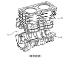
図1には、従来技術に基づき2つの部分から製造されたコンプレッサケースが示されている。このコンプレッサケースは、ケース部分11および12から成っている。コンプレッサケースの、クランクシャフトが導入される一方の端部13では、駆動源との接続部にT字形のシールが必要な点が欠点である。このシールは漏れを生じやすい。
FIG. 1 shows a compressor case manufactured from two parts according to the prior art. This compressor case consists of
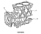
図2には、従来技術に基づく別のコンプレッサケースが示されている。このケースも、2つの部分21および22から製造されている。駆動源に対する接続用には、付加的なフランジ23が設けられている。このフランジにより、両ケース部分21および22相互のシールは、駆動源接続部に対するシールから分離されている。これにより、漏れの危険は縮小されるが、手間のかかる組立が依然として必要とされている点が欠点であり、かつこのために必要なねじやナットに、ユーザはしばしば空間的な狭さのため、接近することが困難である。
FIG. 2 shows another compressor case according to the prior art. This case is also manufactured from two
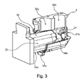
図3には、本発明によるケース3の製造が示されている。このケース3は、クランク室31ならびに第1のシリンダ室32aおよび第2のシリンダ室32bを有している。クランク室31は、2つの端部31aおよび31bを有している。クランク室31は端部31aに開口33を有しており、開口33を介してクランクシャフトをクランク室31内へ導入することができる。図3に示した状態では、この開口33内とクランク室31の一部とに、成形マンドレル34の端部34aおよび34bが位置している。この成形マンドレル34は、その端部34aから第2の端部34bまで先細になっている。図3に示した位置では、流し込まれた材料が冷えた後で、成形マンドレル34は既に、ケース3から部分的に引き出された状態にある。
FIG. 3 shows the production of the case 3 according to the invention. The case 3 has a
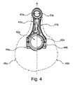
図4には、図3に示したコンプレッサケースの実施例において使用される2つのコネクティングロッドの比較図が示されている。線Aの左側には、第1のコネクティングロッド41aと、第1のコネクティングロッド41aがクランク室内で必要とする運動空間45aとが書き込まれている。線Aの右側には、第2のコネクティングロッド41bと、第2のコネクティングロッド41bがクランク室内で必要とする運動空間45bとが書き込まれている。第2のコネクティングロッド41bは、第1のシリンダ室32aよりも開口33から遠く離れたシリンダ室32b内で使用される。シリンダ室32a内では、第1のコネクティングロッド41aが使用される。シリンダ室32aに供与されている運動空間の方が大きくなっている。
FIG. 4 shows a comparative view of the two connecting rods used in the compressor case embodiment shown in FIG. On the left side of the line A, a first connecting
第1のコネクティングロッド41aは、第1のコネクティングアイ42aと、第2のコネクティングアイ43aとを有している。第1のコネクティングロッド41aは、第1のコネクティングアイ42aで以てクランクシャフトに回動可能に、かつ回転軸線をクランクシャフトの回転軸線に対してずらされて、支持されている。これにより第1のコネクティングロッド41aは、クランクシャフトが1回転することにより、1回昇降運動させられるようになっている。この運動は、ピストンに対して回動可能に支持された第2のコネクティングアイ43aにより、ピストンの昇降運動に変換される。第1のコネクティングアイ42aを包囲する領域は、符号44aで示されている。クランクシャフトを中心とした運動における前記領域の最大作用半径が、第1のコネクティングロッド41aがクランク室内で必要とする運動空間45aを決定する。
The
第2のコネクティングロッド41bも同様に第1のコネクティングアイ42bを有しており、第1のコネクティングアイ42bで以てクランクシャフトに支持されている。第2のコネクティングロッド41bは、その第2のコネクティングアイ43bで以て、第2のピストンに支持されている。コネクティングアイ42bは、領域44bにより包囲されており、領域44bの最大作用半径により、コネクティングロッド全体がクランク室31内で必要とする運動空間45bが決定される。第2のコネクティングロッド41bの運動空間45bは、第1のコネクティングロッド41aの運動空間45aよりも小さくなっている。これは、シリンダ室32bの場所におけるクランク室31の内径が、シリンダ室32aの場所に比べて先細に縮小された、という事実を考慮したものである。
Similarly, the second connecting
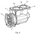
図5には、完成した本発明によるケース5の外観図が示されている。クランク軸を導入することができる開口51には、フランジ52が被せ嵌められている。ケース5がコンプレッサで使用される場合には、このフランジ52に駆動部が接続される。これに対してケース5がエンジンで使用される場合には、フランジ52に被動部が接続される。シリンダ室53aおよび53bは、部分的にのみケース5内に位置しており、取付け手段55を備えた基底板54で終わっている。基底板54には後でシリンダヘッドが取り付けられる。ピストンは、シリンダ室53aおよび53bのアルミニウム上で直接に摺動するのではなく、プレス嵌めされたシリンダライナ上で摺動し、シリンダライナは、摩耗した場合には交換可能である。
FIG. 5 shows an external view of the completed case 5 according to the present invention. A flange 52 is fitted over the
ケースは、高圧鋳造法で製造され得るが、例えば砂型鋳造または金型鋳造等の別のアルミニウム鋳造法でも製造され得る。またケースは、必ずしもアルミニウムから製造されていなくてもよく、例えば鋳鉄から製造されていてもよい。 The case may be manufactured by a high pressure casting process, but may also be manufactured by another aluminum casting process such as sand casting or mold casting. Moreover, the case does not necessarily need to be manufactured from aluminum, for example, may be manufactured from cast iron.
11,12 ケース部分
21,22 ケース部分
3 ケース
31 クランク室
31a,31b クランク室31の端部
32a,32b シリンダ室
33 クランク室31の端部31aに形成された開口
34 成形マンドレル
34a,34b 成形マンドレル34の端部
41a,41b コネクティングロッド
42a,42b コネクティングロッド41aおよび41bの第1のコネクティングアイ
43a,43b コネクティングロッド41aおよび41bの第2のコネクティングアイ
44a,44b 第1のコネクティングアイ42aもしくは42bを包囲する領域
45a,45b クランク室31内のコネクティングロッド41a,41bの運動空間
5 ケース
51 ケース5の開口
52 フランジ
53a,53b シリンダ室
54 基底板
55 取付け手段
DESCRIPTION OF
Claims (12)
前記クランク室(31)の内径は、前記第1の端面(31a)から第2の端面(31b)まで単調に先細に縮小していることを特徴とする、エンジンまたはコンプレッサ用のケース(3,5)。 A case (3, 5) for an engine or a compressor, and an elongated crank chamber (31) having two end faces (31a, 31b) for accommodating the crankshaft, and a reciprocating motion by rotation of the crankshaft. And at least one cylinder chamber (32a, 32b, 53a, 53b) for accommodating the piston to be formed, and the crank chamber (31) has an opening (33, 51) in the first end surface (31a). And the crankshaft can be introduced into the crank chamber (31) through the openings (33, 51).
An inner diameter of the crank chamber (31) monotonously decreases from the first end surface (31a) to the second end surface (31b), and the case for an engine or compressor (3, 5).
各1つのピストンを収容するための少なくとも2つのシリンダ室(32a,32b,53a,53b)を備えた、請求項1から5までのいずれか1項記載のケース(3,5)と、
クランクシャフトと、
シリンダ室毎に1つのコネクティングロッド(41a,41b)とを有しており、該コネクティングロッド(41a,41b)は、第1のコネクティングアイ(42a,42b)で以て前記クランクシャフトに、かつ第2のコネクティングアイ(43a,43b)で以て、前記シリンダ室(32a,32b,53a,53b)内で摺動するピストンに、それぞれ回動可能に支持されているものにおいて、
前記クランクシャフトの軸線に沿って支持された2つの前記コネクティングロッド(41a,41b)を比べると、前記クランク室(31)の各内径と共に、前記第1のコネクティングアイ(42a,42b)の領域(44a,44b)の前記コネクティングロッド(41a,41b)の外径および/または前記第1のコネクティングアイ(42a,42b)の内径も、先細に縮小していることを特徴とする、エンジンまたはコンプレッサ。 An engine or compressor,
Case (3, 5) according to any one of claims 1 to 5, comprising at least two cylinder chambers (32a, 32b, 53a, 53b) for accommodating each one piston,
A crankshaft,
Each cylinder chamber has one connecting rod (41a, 41b), and the connecting rod (41a, 41b) is connected to the crankshaft by the first connecting eye (42a, 42b) and to the first shaft. With two connecting eyes (43a, 43b), the pistons sliding in the cylinder chambers (32a, 32b, 53a, 53b) are respectively supported rotatably.
When the two connecting rods (41a, 41b) supported along the axis of the crankshaft are compared, the inner diameter of the crank chamber (31) and the region of the first connecting eye (42a, 42b) ( 44. An engine or compressor characterized in that the outer diameter of the connecting rod (41a, 41b) of 44a, 44b) and / or the inner diameter of the first connecting eye (42a, 42b) is also tapered.
当該エンジンまたはコンプレッサを車両のエンジンルーム内に取り付けるように形成されており、かつ/または
前記クランクシャフトを介して駆動される別のユニットをエンジンまたはコンプレッサに取り付けるように形成されている、請求項8または9記載のエンジンまたはコンプレッサ。 The flange is
9. The engine or compressor is configured for mounting in an engine room of a vehicle and / or is configured to mount another unit driven through the crankshaft to the engine or compressor. Or the engine or compressor of 9.
2つの端部(34a,34b)を有していて、第1の端部(34a)から第2の端部(34b)に向かって外径が単調に先細に縮小されている細長い成形マンドレル(34)をケース材料で鋳包むことにより、前記クランク室(31)が製造されることを特徴とする、製造方法。 In the manufacturing method of the case (3, 5) according to any one of claims 1 to 5,
An elongated molded mandrel having two ends (34a, 34b), whose outer diameter is monotonously tapered from the first end (34a) to the second end (34b). 34), the crank chamber (31) is manufactured by casting it with a case material.
Applications Claiming Priority (3)
| Application Number | Priority Date | Filing Date | Title |
|---|---|---|---|
| DE102015101459.9 | 2015-02-02 | ||
| DE102015101459.9A DE102015101459A1 (en) | 2015-02-02 | 2015-02-02 | Housing for a motor or compressor |
| PCT/EP2016/051739 WO2016124466A1 (en) | 2015-02-02 | 2016-01-28 | Housing for a motor or compressor |
Publications (2)
| Publication Number | Publication Date |
|---|---|
| JP2018505995A true JP2018505995A (en) | 2018-03-01 |
| JP6530511B2 JP6530511B2 (en) | 2019-06-12 |
Family
ID=55236378
Family Applications (1)
| Application Number | Title | Priority Date | Filing Date |
|---|---|---|---|
| JP2017558774A Expired - Fee Related JP6530511B2 (en) | 2015-02-02 | 2016-01-28 | Case for engine or compressor |
Country Status (10)
| Country | Link |
|---|---|
| US (1) | US10458401B2 (en) |
| EP (1) | EP3253960B1 (en) |
| JP (1) | JP6530511B2 (en) |
| KR (1) | KR102470735B1 (en) |
| CN (1) | CN107208570B (en) |
| BR (1) | BR112017014622B1 (en) |
| DE (1) | DE102015101459A1 (en) |
| RU (1) | RU2664606C1 (en) |
| TR (1) | TR201907741T4 (en) |
| WO (1) | WO2016124466A1 (en) |
Families Citing this family (5)
| Publication number | Priority date | Publication date | Assignee | Title |
|---|---|---|---|---|
| EP3692262B1 (en) * | 2017-09-28 | 2023-05-03 | Koninklijke Philips N.V. | Versatile housing of compressor motors |
| CN108266283B (en) * | 2018-02-01 | 2024-03-19 | 成都桐林铸造实业有限公司 | Supercharged engine cylinder body and automobile engine |
| DE102018111059A1 (en) * | 2018-05-08 | 2019-11-14 | Speck-Kolbenpumpenfabrik Otto Speck Gmbh & Co Kg | DRIVE FOR A PISTON PUMP OR COMPRESSOR |
| DE102018128111A1 (en) | 2018-11-09 | 2020-05-14 | Knorr-Bremse Systeme für Nutzfahrzeuge GmbH | Housing as well as compressor and compressor unit with such a housing |
| EP4599168A1 (en) * | 2022-10-07 | 2025-08-13 | ZF Commercial Vehicle Control Systems India Limited | Air compressor housing for an air compressor of a commercial vehicle, method of producing such a compressor and use of a hypereutectic aluminium alloy therefore |
Citations (9)
| Publication number | Priority date | Publication date | Assignee | Title |
|---|---|---|---|---|
| JPS49132308U (en) * | 1973-03-20 | 1974-11-14 | ||
| JPS5981785U (en) * | 1982-11-24 | 1984-06-02 | ダイキン工業株式会社 | Hermetic compressor structure |
| JPH0368576U (en) * | 1989-11-09 | 1991-07-05 | ||
| JPH0599068A (en) * | 1991-10-04 | 1993-04-20 | Kubota Corp | Crankcase of multi-cylinder engine |
| JPH0564484U (en) * | 1992-02-04 | 1993-08-27 | マックス株式会社 | air compressor |
| JP2003214173A (en) * | 2002-01-28 | 2003-07-30 | Ogawa Seiki Kk | Engine for model |
| JP2005344727A (en) * | 1999-01-25 | 2005-12-15 | Briggs & Stratton Corp | Four-stroke internal combustion engine |
| JP2006183530A (en) * | 2004-12-27 | 2006-07-13 | Hitachi Ltd | Reciprocating compressor |
| JP2010502881A (en) * | 2006-09-08 | 2010-01-28 | クノル−ブレムゼ ジステーメ フューア ヌッツファールツォイゲ ゲゼルシャフト ミット ベシュレンクテル ハフツング | Air compressor with crank casing made of cast aluminum |
Family Cites Families (7)
| Publication number | Priority date | Publication date | Assignee | Title |
|---|---|---|---|---|
| FR461594A (en) * | 1913-07-26 | 1914-01-06 | Ets De Dion Bouton | Device for mounting crankshafts in engines |
| AT182576B (en) * | 1953-01-13 | 1955-07-11 | Norbert Ing Riedel | Multi-cylinder two-stroke engine with a crankcase serving as a charge pump |
| FR1191087A (en) * | 1957-04-20 | 1959-10-16 | Magneti Marelli Spa | Compressor |
| SU546431A1 (en) * | 1974-05-31 | 1977-02-15 | The method of manufacture of castings with internal cavities | |
| SU891998A1 (en) * | 1976-05-19 | 1981-12-23 | Предприятие П/Я А-3833 | Multicylinder i.c. engine crankcase |
| DE19532326C1 (en) * | 1995-09-01 | 1997-01-02 | Daimler Benz Ag | Crankcase made of light metal for IC engine |
| JP3999340B2 (en) * | 1997-12-10 | 2007-10-31 | ヤマハ発動機株式会社 | Cylinder block structure |
-
2015
- 2015-02-02 DE DE102015101459.9A patent/DE102015101459A1/en not_active Ceased
-
2016
- 2016-01-28 EP EP16701669.0A patent/EP3253960B1/en active Active
- 2016-01-28 BR BR112017014622-3A patent/BR112017014622B1/en active IP Right Grant
- 2016-01-28 KR KR1020177021377A patent/KR102470735B1/en active Active
- 2016-01-28 RU RU2017130685A patent/RU2664606C1/en active
- 2016-01-28 CN CN201680008442.8A patent/CN107208570B/en active Active
- 2016-01-28 WO PCT/EP2016/051739 patent/WO2016124466A1/en not_active Ceased
- 2016-01-28 JP JP2017558774A patent/JP6530511B2/en not_active Expired - Fee Related
- 2016-01-28 TR TR2019/07741T patent/TR201907741T4/en unknown
-
2017
- 2017-08-01 US US15/665,942 patent/US10458401B2/en active Active
Patent Citations (9)
| Publication number | Priority date | Publication date | Assignee | Title |
|---|---|---|---|---|
| JPS49132308U (en) * | 1973-03-20 | 1974-11-14 | ||
| JPS5981785U (en) * | 1982-11-24 | 1984-06-02 | ダイキン工業株式会社 | Hermetic compressor structure |
| JPH0368576U (en) * | 1989-11-09 | 1991-07-05 | ||
| JPH0599068A (en) * | 1991-10-04 | 1993-04-20 | Kubota Corp | Crankcase of multi-cylinder engine |
| JPH0564484U (en) * | 1992-02-04 | 1993-08-27 | マックス株式会社 | air compressor |
| JP2005344727A (en) * | 1999-01-25 | 2005-12-15 | Briggs & Stratton Corp | Four-stroke internal combustion engine |
| JP2003214173A (en) * | 2002-01-28 | 2003-07-30 | Ogawa Seiki Kk | Engine for model |
| JP2006183530A (en) * | 2004-12-27 | 2006-07-13 | Hitachi Ltd | Reciprocating compressor |
| JP2010502881A (en) * | 2006-09-08 | 2010-01-28 | クノル−ブレムゼ ジステーメ フューア ヌッツファールツォイゲ ゲゼルシャフト ミット ベシュレンクテル ハフツング | Air compressor with crank casing made of cast aluminum |
Also Published As
| Publication number | Publication date |
|---|---|
| RU2664606C1 (en) | 2018-08-21 |
| KR20170109566A (en) | 2017-09-29 |
| JP6530511B2 (en) | 2019-06-12 |
| DE102015101459A1 (en) | 2016-08-04 |
| EP3253960A1 (en) | 2017-12-13 |
| KR102470735B1 (en) | 2022-11-24 |
| WO2016124466A1 (en) | 2016-08-11 |
| EP3253960B1 (en) | 2019-03-13 |
| BR112017014622B1 (en) | 2022-09-27 |
| US20170328356A1 (en) | 2017-11-16 |
| CN107208570B (en) | 2021-03-26 |
| TR201907741T4 (en) | 2019-06-21 |
| CN107208570A (en) | 2017-09-26 |
| BR112017014622A2 (en) | 2018-01-23 |
| US10458401B2 (en) | 2019-10-29 |
Similar Documents
| Publication | Publication Date | Title |
|---|---|---|
| JP6530511B2 (en) | Case for engine or compressor | |
| JP3199996U (en) | Rotation mechanism of air compressor | |
| KR101457664B1 (en) | Piston for refrigeration compressor | |
| CN206221202U (en) | Reciprocating compressor | |
| CN101338743B (en) | Reciprocating-piston compressor body | |
| HK1241952A1 (en) | Housing for a motor or compressor | |
| HK1241952B (en) | Housing for a motor or compressor | |
| US20090217902A1 (en) | Method for assembling a crankshaft drive and piston compressor | |
| JP6238999B2 (en) | Piston for internal combustion engine | |
| CN118574987A (en) | Cylinder liner and reciprocating engine with same | |
| JP6595251B2 (en) | air compressor | |
| JP2003214173A (en) | Engine for model | |
| CN107218223A (en) | Rotary compressor | |
| JP4499550B2 (en) | Reciprocating compressor | |
| WO2019075686A1 (en) | Air compressor cylinder, air compressor, vehicle seat, and vehicle | |
| KR101401058B1 (en) | The swash plate of swash plate compressor automotive air conditioners | |
| CN216950825U (en) | Multipurpose compatible casing of piston pump and diaphragm pump | |
| CN208669605U (en) | Compressor | |
| JP2016008533A (en) | air compressor | |
| JP6654388B2 (en) | Compressor | |
| CN1316595A (en) | Compressor piston and method for producing compressor piston | |
| JPS59133817A (en) | Crank-shaft structure | |
| CN102734127B (en) | Piston compressor | |
| WO2016084137A1 (en) | Compressor | |
| CN102029374A (en) | Method for casting cylinder body of compressor |
Legal Events
| Date | Code | Title | Description |
|---|---|---|---|
| A621 | Written request for application examination |
Free format text: JAPANESE INTERMEDIATE CODE: A621 Effective date: 20171002 |
|
| A977 | Report on retrieval |
Free format text: JAPANESE INTERMEDIATE CODE: A971007 Effective date: 20181012 |
|
| A131 | Notification of reasons for refusal |
Free format text: JAPANESE INTERMEDIATE CODE: A131 Effective date: 20181022 |
|
| A521 | Request for written amendment filed |
Free format text: JAPANESE INTERMEDIATE CODE: A523 Effective date: 20190121 |
|
| TRDD | Decision of grant or rejection written | ||
| A01 | Written decision to grant a patent or to grant a registration (utility model) |
Free format text: JAPANESE INTERMEDIATE CODE: A01 Effective date: 20190417 |
|
| A61 | First payment of annual fees (during grant procedure) |
Free format text: JAPANESE INTERMEDIATE CODE: A61 Effective date: 20190516 |
|
| R150 | Certificate of patent or registration of utility model |
Ref document number: 6530511 Country of ref document: JP Free format text: JAPANESE INTERMEDIATE CODE: R150 |
|
| LAPS | Cancellation because of no payment of annual fees |