JP2018506830A - Vehicle light assembly and lighting method - Google Patents
Vehicle light assembly and lighting method Download PDFInfo
- Publication number
- JP2018506830A JP2018506830A JP2017545570A JP2017545570A JP2018506830A JP 2018506830 A JP2018506830 A JP 2018506830A JP 2017545570 A JP2017545570 A JP 2017545570A JP 2017545570 A JP2017545570 A JP 2017545570A JP 2018506830 A JP2018506830 A JP 2018506830A
- Authority
- JP
- Japan
- Prior art keywords
- light
- light guide
- assembly
- formations
- light assembly
- Prior art date
- Legal status (The legal status is an assumption and is not a legal conclusion. Google has not performed a legal analysis and makes no representation as to the accuracy of the status listed.)
- Granted
Links
Images

Classifications
-
- B—PERFORMING OPERATIONS; TRANSPORTING
- B60—VEHICLES IN GENERAL
- B60Q—ARRANGEMENT OF SIGNALLING OR LIGHTING DEVICES, THE MOUNTING OR SUPPORTING THEREOF OR CIRCUITS THEREFOR, FOR VEHICLES IN GENERAL
- B60Q1/00—Arrangement of optical signalling or lighting devices, the mounting or supporting thereof or circuits therefor
- B60Q1/0011—Arrangement of optical signalling or lighting devices, the mounting or supporting thereof or circuits therefor with light guides for distributing the light between several lighting or signalling devices
-
- B—PERFORMING OPERATIONS; TRANSPORTING
- B60—VEHICLES IN GENERAL
- B60Q—ARRANGEMENT OF SIGNALLING OR LIGHTING DEVICES, THE MOUNTING OR SUPPORTING THEREOF OR CIRCUITS THEREFOR, FOR VEHICLES IN GENERAL
- B60Q1/00—Arrangement of optical signalling or lighting devices, the mounting or supporting thereof or circuits therefor
- B60Q1/0029—Spatial arrangement
- B60Q1/0041—Spatial arrangement of several lamps in relation to each other
- B60Q1/0052—Spatial arrangement of several lamps in relation to each other concentric
-
- B—PERFORMING OPERATIONS; TRANSPORTING
- B29—WORKING OF PLASTICS; WORKING OF SUBSTANCES IN A PLASTIC STATE IN GENERAL
- B29D—PRODUCING PARTICULAR ARTICLES FROM PLASTICS OR FROM SUBSTANCES IN A PLASTIC STATE
- B29D11/00—Producing optical elements, e.g. lenses or prisms
- B29D11/00663—Production of light guides
-
- B—PERFORMING OPERATIONS; TRANSPORTING
- B60—VEHICLES IN GENERAL
- B60Q—ARRANGEMENT OF SIGNALLING OR LIGHTING DEVICES, THE MOUNTING OR SUPPORTING THEREOF OR CIRCUITS THEREFOR, FOR VEHICLES IN GENERAL
- B60Q1/00—Arrangement of optical signalling or lighting devices, the mounting or supporting thereof or circuits therefor
-
- B—PERFORMING OPERATIONS; TRANSPORTING
- B60—VEHICLES IN GENERAL
- B60Q—ARRANGEMENT OF SIGNALLING OR LIGHTING DEVICES, THE MOUNTING OR SUPPORTING THEREOF OR CIRCUITS THEREFOR, FOR VEHICLES IN GENERAL
- B60Q1/00—Arrangement of optical signalling or lighting devices, the mounting or supporting thereof or circuits therefor
- B60Q1/02—Arrangement of optical signalling or lighting devices, the mounting or supporting thereof or circuits therefor the devices being primarily intended to illuminate the way ahead or to illuminate other areas of way or environments
- B60Q1/04—Arrangement of optical signalling or lighting devices, the mounting or supporting thereof or circuits therefor the devices being primarily intended to illuminate the way ahead or to illuminate other areas of way or environments the devices being headlights
-
- B—PERFORMING OPERATIONS; TRANSPORTING
- B60—VEHICLES IN GENERAL
- B60Q—ARRANGEMENT OF SIGNALLING OR LIGHTING DEVICES, THE MOUNTING OR SUPPORTING THEREOF OR CIRCUITS THEREFOR, FOR VEHICLES IN GENERAL
- B60Q1/00—Arrangement of optical signalling or lighting devices, the mounting or supporting thereof or circuits therefor
- B60Q1/26—Arrangement of optical signalling or lighting devices, the mounting or supporting thereof or circuits therefor the devices being primarily intended to indicate the vehicle, or parts thereof, or to give signals, to other traffic
- B60Q1/2696—Mounting of devices using LEDs
-
- B—PERFORMING OPERATIONS; TRANSPORTING
- B60—VEHICLES IN GENERAL
- B60Q—ARRANGEMENT OF SIGNALLING OR LIGHTING DEVICES, THE MOUNTING OR SUPPORTING THEREOF OR CIRCUITS THEREFOR, FOR VEHICLES IN GENERAL
- B60Q1/00—Arrangement of optical signalling or lighting devices, the mounting or supporting thereof or circuits therefor
- B60Q1/26—Arrangement of optical signalling or lighting devices, the mounting or supporting thereof or circuits therefor the devices being primarily intended to indicate the vehicle, or parts thereof, or to give signals, to other traffic
- B60Q1/28—Arrangement of optical signalling or lighting devices, the mounting or supporting thereof or circuits therefor the devices being primarily intended to indicate the vehicle, or parts thereof, or to give signals, to other traffic for indicating front of vehicle
-
- F—MECHANICAL ENGINEERING; LIGHTING; HEATING; WEAPONS; BLASTING
- F21—LIGHTING
- F21S—NON-PORTABLE LIGHTING DEVICES; SYSTEMS THEREOF; VEHICLE LIGHTING DEVICES SPECIALLY ADAPTED FOR VEHICLE EXTERIORS
- F21S10/00—Lighting devices or systems producing a varying lighting effect
- F21S10/005—Lighting devices or systems producing a varying lighting effect using light guides
-
- F—MECHANICAL ENGINEERING; LIGHTING; HEATING; WEAPONS; BLASTING
- F21—LIGHTING
- F21S—NON-PORTABLE LIGHTING DEVICES; SYSTEMS THEREOF; VEHICLE LIGHTING DEVICES SPECIALLY ADAPTED FOR VEHICLE EXTERIORS
- F21S41/00—Illuminating devices specially adapted for vehicle exteriors, e.g. headlamps
-
- F—MECHANICAL ENGINEERING; LIGHTING; HEATING; WEAPONS; BLASTING
- F21—LIGHTING
- F21S—NON-PORTABLE LIGHTING DEVICES; SYSTEMS THEREOF; VEHICLE LIGHTING DEVICES SPECIALLY ADAPTED FOR VEHICLE EXTERIORS
- F21S41/00—Illuminating devices specially adapted for vehicle exteriors, e.g. headlamps
- F21S41/10—Illuminating devices specially adapted for vehicle exteriors, e.g. headlamps characterised by the light source
- F21S41/14—Illuminating devices specially adapted for vehicle exteriors, e.g. headlamps characterised by the light source characterised by the type of light source
-
- F—MECHANICAL ENGINEERING; LIGHTING; HEATING; WEAPONS; BLASTING
- F21—LIGHTING
- F21S—NON-PORTABLE LIGHTING DEVICES; SYSTEMS THEREOF; VEHICLE LIGHTING DEVICES SPECIALLY ADAPTED FOR VEHICLE EXTERIORS
- F21S41/00—Illuminating devices specially adapted for vehicle exteriors, e.g. headlamps
- F21S41/10—Illuminating devices specially adapted for vehicle exteriors, e.g. headlamps characterised by the light source
- F21S41/14—Illuminating devices specially adapted for vehicle exteriors, e.g. headlamps characterised by the light source characterised by the type of light source
- F21S41/141—Light emitting diodes [LED]
-
- F—MECHANICAL ENGINEERING; LIGHTING; HEATING; WEAPONS; BLASTING
- F21—LIGHTING
- F21S—NON-PORTABLE LIGHTING DEVICES; SYSTEMS THEREOF; VEHICLE LIGHTING DEVICES SPECIALLY ADAPTED FOR VEHICLE EXTERIORS
- F21S41/00—Illuminating devices specially adapted for vehicle exteriors, e.g. headlamps
- F21S41/20—Illuminating devices specially adapted for vehicle exteriors, e.g. headlamps characterised by refractors, transparent cover plates, light guides or filters
- F21S41/24—Light guides
-
- F—MECHANICAL ENGINEERING; LIGHTING; HEATING; WEAPONS; BLASTING
- F21—LIGHTING
- F21S—NON-PORTABLE LIGHTING DEVICES; SYSTEMS THEREOF; VEHICLE LIGHTING DEVICES SPECIALLY ADAPTED FOR VEHICLE EXTERIORS
- F21S41/00—Illuminating devices specially adapted for vehicle exteriors, e.g. headlamps
- F21S41/30—Illuminating devices specially adapted for vehicle exteriors, e.g. headlamps characterised by reflectors
- F21S41/32—Optical layout thereof
-
- F—MECHANICAL ENGINEERING; LIGHTING; HEATING; WEAPONS; BLASTING
- F21—LIGHTING
- F21S—NON-PORTABLE LIGHTING DEVICES; SYSTEMS THEREOF; VEHICLE LIGHTING DEVICES SPECIALLY ADAPTED FOR VEHICLE EXTERIORS
- F21S43/00—Signalling devices specially adapted for vehicle exteriors, e.g. brake lamps, direction indicator lights or reversing lights
-
- F—MECHANICAL ENGINEERING; LIGHTING; HEATING; WEAPONS; BLASTING
- F21—LIGHTING
- F21S—NON-PORTABLE LIGHTING DEVICES; SYSTEMS THEREOF; VEHICLE LIGHTING DEVICES SPECIALLY ADAPTED FOR VEHICLE EXTERIORS
- F21S43/00—Signalling devices specially adapted for vehicle exteriors, e.g. brake lamps, direction indicator lights or reversing lights
- F21S43/10—Signalling devices specially adapted for vehicle exteriors, e.g. brake lamps, direction indicator lights or reversing lights characterised by the light source
- F21S43/13—Signalling devices specially adapted for vehicle exteriors, e.g. brake lamps, direction indicator lights or reversing lights characterised by the light source characterised by the type of light source
- F21S43/14—Light emitting diodes [LED]
-
- F—MECHANICAL ENGINEERING; LIGHTING; HEATING; WEAPONS; BLASTING
- F21—LIGHTING
- F21S—NON-PORTABLE LIGHTING DEVICES; SYSTEMS THEREOF; VEHICLE LIGHTING DEVICES SPECIALLY ADAPTED FOR VEHICLE EXTERIORS
- F21S43/00—Signalling devices specially adapted for vehicle exteriors, e.g. brake lamps, direction indicator lights or reversing lights
- F21S43/20—Signalling devices specially adapted for vehicle exteriors, e.g. brake lamps, direction indicator lights or reversing lights characterised by refractors, transparent cover plates, light guides or filters
- F21S43/235—Light guides
- F21S43/236—Light guides characterised by the shape of the light guide
- F21S43/241—Light guides characterised by the shape of the light guide of complex shape
-
- F—MECHANICAL ENGINEERING; LIGHTING; HEATING; WEAPONS; BLASTING
- F21—LIGHTING
- F21S—NON-PORTABLE LIGHTING DEVICES; SYSTEMS THEREOF; VEHICLE LIGHTING DEVICES SPECIALLY ADAPTED FOR VEHICLE EXTERIORS
- F21S43/00—Signalling devices specially adapted for vehicle exteriors, e.g. brake lamps, direction indicator lights or reversing lights
- F21S43/20—Signalling devices specially adapted for vehicle exteriors, e.g. brake lamps, direction indicator lights or reversing lights characterised by refractors, transparent cover plates, light guides or filters
- F21S43/235—Light guides
- F21S43/242—Light guides characterised by the emission area
- F21S43/245—Light guides characterised by the emission area emitting light from one or more of its major surfaces
-
- F—MECHANICAL ENGINEERING; LIGHTING; HEATING; WEAPONS; BLASTING
- F21—LIGHTING
- F21S—NON-PORTABLE LIGHTING DEVICES; SYSTEMS THEREOF; VEHICLE LIGHTING DEVICES SPECIALLY ADAPTED FOR VEHICLE EXTERIORS
- F21S43/00—Signalling devices specially adapted for vehicle exteriors, e.g. brake lamps, direction indicator lights or reversing lights
- F21S43/20—Signalling devices specially adapted for vehicle exteriors, e.g. brake lamps, direction indicator lights or reversing lights characterised by refractors, transparent cover plates, light guides or filters
- F21S43/235—Light guides
- F21S43/249—Light guides with two or more light sources being coupled into the light guide
-
- F—MECHANICAL ENGINEERING; LIGHTING; HEATING; WEAPONS; BLASTING
- F21—LIGHTING
- F21S—NON-PORTABLE LIGHTING DEVICES; SYSTEMS THEREOF; VEHICLE LIGHTING DEVICES SPECIALLY ADAPTED FOR VEHICLE EXTERIORS
- F21S43/00—Signalling devices specially adapted for vehicle exteriors, e.g. brake lamps, direction indicator lights or reversing lights
- F21S43/40—Signalling devices specially adapted for vehicle exteriors, e.g. brake lamps, direction indicator lights or reversing lights characterised by the combination of reflectors and refractors
-
- B—PERFORMING OPERATIONS; TRANSPORTING
- B60—VEHICLES IN GENERAL
- B60Q—ARRANGEMENT OF SIGNALLING OR LIGHTING DEVICES, THE MOUNTING OR SUPPORTING THEREOF OR CIRCUITS THEREFOR, FOR VEHICLES IN GENERAL
- B60Q2400/00—Special features or arrangements of exterior signal lamps for vehicles
- B60Q2400/30—Daytime running lights [DRL], e.g. circuits or arrangements therefor
-
- B—PERFORMING OPERATIONS; TRANSPORTING
- B60—VEHICLES IN GENERAL
- B60Q—ARRANGEMENT OF SIGNALLING OR LIGHTING DEVICES, THE MOUNTING OR SUPPORTING THEREOF OR CIRCUITS THEREFOR, FOR VEHICLES IN GENERAL
- B60Q2400/00—Special features or arrangements of exterior signal lamps for vehicles
- B60Q2400/40—Welcome lights, i.e. specific or existing exterior lamps to assist leaving or approaching the vehicle
-
- F—MECHANICAL ENGINEERING; LIGHTING; HEATING; WEAPONS; BLASTING
- F21—LIGHTING
- F21Y—INDEXING SCHEME ASSOCIATED WITH SUBCLASSES F21K, F21L, F21S and F21V, RELATING TO THE FORM OR THE KIND OF THE LIGHT SOURCES OR OF THE COLOUR OF THE LIGHT EMITTED
- F21Y2105/00—Planar light sources
- F21Y2105/10—Planar light sources comprising a two-dimensional [2D] array of point-like light-generating elements
-
- F—MECHANICAL ENGINEERING; LIGHTING; HEATING; WEAPONS; BLASTING
- F21—LIGHTING
- F21Y—INDEXING SCHEME ASSOCIATED WITH SUBCLASSES F21K, F21L, F21S and F21V, RELATING TO THE FORM OR THE KIND OF THE LIGHT SOURCES OR OF THE COLOUR OF THE LIGHT EMITTED
- F21Y2105/00—Planar light sources
- F21Y2105/10—Planar light sources comprising a two-dimensional [2D] array of point-like light-generating elements
- F21Y2105/14—Planar light sources comprising a two-dimensional [2D] array of point-like light-generating elements characterised by the overall shape of the two-dimensional [2D] array
- F21Y2105/18—Planar light sources comprising a two-dimensional [2D] array of point-like light-generating elements characterised by the overall shape of the two-dimensional [2D] array annular; polygonal other than square or rectangular, e.g. for spotlights or for generating an axially symmetrical light beam
-
- F—MECHANICAL ENGINEERING; LIGHTING; HEATING; WEAPONS; BLASTING
- F21—LIGHTING
- F21Y—INDEXING SCHEME ASSOCIATED WITH SUBCLASSES F21K, F21L, F21S and F21V, RELATING TO THE FORM OR THE KIND OF THE LIGHT SOURCES OR OF THE COLOUR OF THE LIGHT EMITTED
- F21Y2115/00—Light-generating elements of semiconductor light sources
- F21Y2115/10—Light-emitting diodes [LED]
Landscapes
- Engineering & Computer Science (AREA)
- General Engineering & Computer Science (AREA)
- Mechanical Engineering (AREA)
- Physics & Mathematics (AREA)
- Microelectronics & Electronic Packaging (AREA)
- Optics & Photonics (AREA)
- Health & Medical Sciences (AREA)
- Manufacturing & Machinery (AREA)
- Ophthalmology & Optometry (AREA)
- Non-Portable Lighting Devices Or Systems Thereof (AREA)
- Lighting Device Outwards From Vehicle And Optical Signal (AREA)
- Planar Illumination Modules (AREA)
Abstract
ヘッドライト等のためのライト・アセンブリであって、ハウジングを有しており、ハウジングは、後方部及び前方部を有しており、使用時には、ハウジングの前方部から光が放射されるようになっている。透明または半透明の光ガイドは、後方部から前方部に向かって延び、且つ、ハウジングによって少なくとも部分的に囲まれている。光ガイドは、その後方部で照明され、且つ、その長さの少なくとも一部に沿って光を放射するように構成されている。カット・ガラスまたはクリスタルのような外観を得るための複数のフォーメーションが形成されており、駐車ライト及びウェルカム・シーケンスの一部として使用されている。【選択図】 図1A light assembly for a headlight or the like, having a housing, and the housing has a rear portion and a front portion, and light is emitted from the front portion of the housing in use. ing. The transparent or translucent light guide extends from the rear part toward the front part and is at least partially surrounded by the housing. The light guide is illuminated at its rear and is configured to emit light along at least a portion of its length. A number of formations have been formed to obtain a cut glass or crystal-like appearance and are used as part of the parking light and welcome sequence. [Selection] Figure 1
Description
本発明は、車両用のライト・アセンブリに関するものであり、それに限定されないが、特に、自動車用外部ライト・アセンブリ、特に、ヘッドライト・アセンブリまたはテールライト・アセンブリに関するものである。また、本発明は、このようなライト・アセンブリの作動方法及びこのようなライト・アセンブリの形成方法に関するものでもある。 The present invention relates to a light assembly for a vehicle, and more particularly, but not exclusively, relates to an automotive external light assembly, in particular a headlight assembly or a taillight assembly. The present invention also relates to a method of operating such a light assembly and a method of forming such a light assembly.
自動車用ライト・アセンブリ(Automotive light assemblies)は、典型的には、ハロゲン・バルブ若しくはキセノン・バルブ(halogen or xenon bulb)等、または、LEDマトリックスが後方に配置される(sits behind)マトリックス・モジュールである交換可能な主光源用の開口部を備えている。一般的な円錐形の反射ハウジング(または"リフレクタ(reflector)")は、外部に向かって光を向けるため、主光源(main light source)の周囲に配置され、また、透明(または半透明)のフロント・レンズが反射ハウジング(reflective housing)の前方に配置されて、アセンブリがふさがれている。 Automotive light assemblies are typically halogen bulbs or xenon bulbs, or matrix modules in which the LED matrix sits behind. An interchangeable main light source opening is provided. A typical conical reflective housing (or “reflector”) is placed around the main light source to direct light towards the outside and is also transparent (or translucent) A front lens is placed in front of the reflective housing to block the assembly.
同フロント・レンズの後に追加の複数の光源を配置してもよく、メイン・ビーム−バルブ(main beam-bulb)、ディップ・ビーム−バルブ(dipped beam-bulb)、及び、インジケータ・バルブ(indicator bulb)等の異なる光源からの光をガイドするため、様々な形状の反射ハウジングを備えていてもよい。LED技術の出現により、複数のLEDのマトリックスによって様々な形状を形成することができる。例えば、昼間走行用ライト(daylight running lights)/駐車ライト(park lights)は、車両の部品の形状と合った、または、形状を強調した、より好ましい形状とすることができる。 Additional light sources may be placed after the front lens, including a main beam-bulb, a dipped beam-bulb, and an indicator bulb. In order to guide light from different light sources such as), various shapes of reflective housings may be provided. With the advent of LED technology, various shapes can be formed by a matrix of multiple LEDs. For example, daylight running lights / park lights can be in a more preferred shape that matches or emphasizes the shape of vehicle components.
特に、高級自動車市場では、自動車用ライト/ライト・アセンブリが、新規な形態をとり、追加の機能を発揮することが望ましい。 In particular, in the luxury car market, it is desirable for automotive lights / light assemblies to take new forms and perform additional functions.
本発明の第1の態様によれば、ハウジングを有するライト・アセンブリであって、ハウジングは、後方部(rear)及び前方部(front)を有しており、使用時には、ハウジングの前方部から光が放射されるようになっており、ライト・アセンブリは、後方部から前方部に向かって延び、且つ、ハウジングによって少なくとも部分的に囲まれた、透明または半透明の光ガイド(light guide)をさらに有しており、光ガイドは、後方部で照明され、且つ、その長さの少なくとも一部に沿って光を放射する(emit)ように構成されているライト・アセンブリを提供する。 According to a first aspect of the present invention, there is provided a light assembly having a housing, the housing having a rear part and a front part, and in use, the light from the front part of the housing. The light assembly further includes a transparent or translucent light guide that extends from the rear portion toward the front portion and is at least partially surrounded by the housing. And the light guide provides a light assembly that is illuminated at the rear and is configured to emit light along at least a portion of its length.
光がその長さに沿って放射される光ガイドを提供することで、所望のパターンの光のフォーメーションを可能にすることができる。特に、光ガイドの長さに沿って光を放射することで、複数のLEDの多くのパターンに欠けている、深さ(depth)と3次元性(three dimensionality)を有する外観を与えることができる。 Providing a light guide in which light is emitted along its length can allow for the formation of a desired pattern of light. In particular, emitting light along the length of the light guide can provide an appearance with depth and three dimensionality that is lacking in many patterns of LEDs. .
ハウジングは、反射性であってもよい。反射ハウジングは、高光沢仕上げ(high-gloss finish)でも、鏡面仕上げ(mirrored)でもよい。 The housing may be reflective. The reflective housing may be high-gloss finish or mirrored.
ライト・アセンブリは、光ガイドの後方部を照明するように構成された光源を備えていてもよい。 The light assembly may comprise a light source configured to illuminate the rear portion of the light guide.
光ガイドは、内面、外面、前方端、後方端、及び、前方端及び後方端の間を延びる通路を有する管状(tubular)であってもよい。 The light guide may be tubular with an inner surface, an outer surface, a front end, a rear end, and a passage extending between the front end and the rear end.
管状形状は、特にカット・ガラス(cut glass)やクリスタルを喚起し、特に、珍しい、魅力的な光のパターンを示すことができる。 Tubular shapes can evoke particularly cut glass and crystals, and in particular can exhibit unusual and attractive light patterns.
光源は、管状の光ガイドの後方端にリング状に配置された複数の光源からなるアレイを有していてもよい。光源は、複数のLEDであってもよい。 The light source may have an array of a plurality of light sources arranged in a ring shape at the rear end of the tubular light guide. The light source may be a plurality of LEDs.
光ガイドには、その表面上/内に、その長さの少なくとも一部に沿って光を放射するための複数のフォーメーション(formations)が形成されていてもよい。 The light guide may have a plurality of formations on / in its surface for emitting light along at least a portion of its length.
光ガイドの表面上/内の複数のフォーメーションは、光ガイドの表面に形成された複数の溝、または、光ガイドの表面の艶消しの複数の線(lines frosted on a surface of the light guide)であってもよい。複数の溝は、V字型であってもよい。複数の溝または複数の線は、使用時に使用者の方に向いた面、すなわち、ハウジングと隣接して配置されている管状光ガイドの径方向内面に形成されていてもよい。 Multiple formations on / in the surface of the light guide are formed by multiple grooves formed on the surface of the light guide, or by lines frosted on a surface of the light guide. There may be. The plurality of grooves may be V-shaped. The plurality of grooves or the plurality of lines may be formed on a surface facing the user when in use, that is, on a radially inner surface of the tubular light guide disposed adjacent to the housing.
複数のフォーメーションは、光ガイドの表面に十字模様を形成していてもよい(criss-cross the surface of the light guide)。 The plurality of formations may form a cross pattern on the surface of the light guide (criss-cross the surface of the light guide).
光ガイドは、一方の表面(例えば、管状光ガイドの内面)に、第1のタイプの複数のフォーメーションが形成されていて、他方の表面(例えば管状光ガイドの外面)に、第2のタイプの複数のフォーメーションが形成されていてもよい。 The light guide has a first type of formation formed on one surface (eg, the inner surface of the tubular light guide) and a second type on the other surface (eg, the outer surface of the tubular light guide). A plurality of formations may be formed.
放射される光のパターンが、カット・ガラスを通る光のパターンを再現するように、一方の表面の第1のタイプの複数のフォーメーションは、複数の溝(grooves)であって、他方の表面の第2のタイプの複数のフォーメーションは、複数のファセット(facets)であってもよい。 The first type of formations on one surface is a plurality of grooves, so that the emitted light pattern reproduces the pattern of light passing through the cut glass. The plurality of formations of the second type may be a plurality of facets.
複数のファセットは、光ガイドの表面から延びる複数のピラミッド形フォーメーション(pyramidal formations)によって形成されていてもよい。 The plurality of facets may be formed by a plurality of pyramidal formations extending from the surface of the light guide.
複数のフォーメーションは、複数のノッチ(notches)、複数のくぼみ(dimples)、複数の隆起部(bumps)等であってもよい。 The plurality of formations may be a plurality of notches, a plurality of dimples, a plurality of bumps, and the like.
光ガイドの厚みは、後方部から前方部に向かうにしたがって減少するように構成されていてもよい。 The thickness of the light guide may be configured to decrease from the rear part toward the front part.
光ガイドは、後方部から前方部に向かうにしたがってフレア状に広がるように(flare)構成されていてもよい。 The light guide may be configured to flare as it goes from the rear part to the front part.
ハウジングの後方部には、メイン・ビーム・バルブ、ディップ・ビーム・バルブまたはマトリックス・モジュールのような主光源を収容する開口部が形成されていてもよい。また、ライト・アセンブリは、そのような主光源を備えていてもよい。光ガイドの後方部を照明する光源は、補助光源(auxiliary light source)であってもよい。 An opening for receiving a main light source such as a main beam bulb, a dip beam bulb or a matrix module may be formed in the rear portion of the housing. The light assembly may also include such a main light source. The light source that illuminates the rear portion of the light guide may be an auxiliary light source.
透明/半透明の光ガイドは、着色されていてもよい(tinted)。典型的には、クリスタルのような外観を呈するようにするために、青または緑に着色されていてもよい。 The transparent / translucent light guide may be tinted. Typically, it may be colored blue or green to give it a crystal-like appearance.
透明/半透明の光ガイドは、プラスチック材料から形成されていてもよい。光ガイドは、射出成形(injection moulded)によって形成されていてもよい。典型的には、2段階射出成形プロセス(two-stage injection moulding process)によって形成されていてもよい。代わりに、複数のフォーメーションは、光ガイドに対して機械加工(machined)されていてもよい。 The transparent / translucent light guide may be formed from a plastic material. The light guide may be formed by injection molding. Typically, it may be formed by a two-stage injection molding process. Alternatively, the plurality of formations may be machined with respect to the light guide.
光ガイドは、その長さに沿って、後方部の光源から受けた光の少なくとも50%を放射するように形成されていてもよい。光ガイドは、その長さに沿って、後方部の光源から受けた光の全てを放射するように形成されていてもよい。 The light guide may be configured to emit at least 50% of the light received from the rear light source along its length. The light guide may be formed to emit all of the light received from the rear light source along its length.
光ガイドの前方部からではなく、主に長さに沿った光の放射は、後方部からの光の相当量が光ガイドを通って、前方部から放射される場合よりも、カット・ガラスまたはクリスタルの外観をより明瞭にする。 The emission of light mainly along the length, not from the front part of the light guide, is less than the cut glass or the case where a considerable amount of light from the rear part is emitted from the front part through the light guide. Make the crystal appearance clearer.
光ガイドは、PMMA(ポリ(メタクリル酸メチル))から形成されていてもよい。 The light guide may be formed from PMMA (poly (methyl methacrylate)).
光ガイドは、ハウジングによって完全に囲まれていてもよい。光ガイドは、ハウジングと隣接して配置されていてもよい。典型的には、光ガイドは、ハウジングの長さに沿って隣接して配置されていてもよい。 The light guide may be completely surrounded by the housing. The light guide may be disposed adjacent to the housing. Typically, the light guides may be located adjacent along the length of the housing.
ライト・アセンブリは、車両用ライト・アセンブリであってもよく、特に、ヘッドライト・アセンブリまたはテールライト・アセンブリ等の外部車両用ライト・アセンブリであってもよい。光ガイドは、駐車ランプであってもよい。 The light assembly may be a vehicle light assembly, in particular an external vehicle light assembly such as a headlight assembly or a taillight assembly. The light guide may be a parking lamp.
本発明の第2の態様によれば、上述の(好ましい態様のいずれかを含む)ライト・アセンブリを備えた自動車を提供する。典型的には、上述のヘッドライト及び/または駐車ライトを備えた自動車を提供する。 According to a second aspect of the present invention there is provided an automobile comprising a light assembly as described above (including any of the preferred aspects). Typically, an automobile is provided with the headlights and / or parking lights described above.
本発明の第3の態様によれば、ライト・アセンブリの作動方法であって、ライト・アセンブリは、ハウジングと、光ガイドと、光源とを備えており、ハウジングは、後方部及び前方部を有しており、使用時には、ハウジングの前方部から光が放射されるようになっており、光ガイドは、透明または半透明であり、後方部から前方部に向かって延び、且つ、ハウジングによって少なくとも部分的に囲まれており、光ガイドは、その後方部で照明され、且つ、その長さの少なくとも一部に沿って光を放射するように構成されており、光ガイドの後方部には、光源が配置されており、当該方法では、光が光ガイドの長さに沿ってゆっくり進むように見えるように、光源から供給される光の強度を徐々に強めることを特徴とするライト・アセンブリの作動方法を提供する。 According to a third aspect of the present invention, there is provided a method for operating a light assembly, the light assembly including a housing, a light guide, and a light source, the housing having a rear portion and a front portion. In use, light is emitted from the front portion of the housing, and the light guide is transparent or translucent, extends from the rear portion toward the front portion, and is at least partially separated by the housing. The light guide is illuminated at its rear portion and is configured to emit light along at least part of its length. The light assembly is characterized in that the light intensity supplied from the light source is gradually increased so that the light appears to travel slowly along the length of the light guide. To provide a dynamic way.
ライト・アセンブリは、好ましい特徴のいずれかまたはすべてを含む、本発明の第1または第2の態様によるライト・アセンブリであってもよい。 The light assembly may be a light assembly according to the first or second aspect of the invention, including any or all of the preferred features.
光ガイドを照明する光ガイドの後方部に配置された光源は、複数の光源からなるアレイ(例えば、複数のLED)であってもよい。そして、光の強度を強めるため、点灯させる複数の光源の数を増加させてもよい。代わりに、例えば、パルスの持続時間を変化させることによって、1つのまたは各光源からの光の強度を徐々に強めるようにしてもよい。 The light source disposed in the rear part of the light guide that illuminates the light guide may be an array of a plurality of light sources (for example, a plurality of LEDs). And in order to strengthen the intensity | strength of light, you may increase the number of the several light source to light. Alternatively, the intensity of light from one or each light source may be gradually increased, for example by changing the duration of the pulse.
3秒から10秒の間に、徐々に光の強度を強めるようにしてもよい。徐々に(例えば、3秒から10秒の間に)光の強度を弱めることをさらに含んでもよい。 The intensity of light may be gradually increased between 3 seconds and 10 seconds. It may further include decreasing the light intensity gradually (eg, between 3 seconds and 10 seconds).
本方法は、光源から供給される光の強度を徐々に強め、次に別の光源(例えば、昼間走行用ライト)を点灯させ、次に光源から供給される光の強度を徐々に弱めることを含んでもよい。 This method involves gradually increasing the intensity of light supplied from the light source, then turning on another light source (eg, daytime running light), and then gradually decreasing the intensity of light supplied from the light source. May be included.
本方法は、ウェルカム・シーケンス(welcome sequence)であってもよく、光ガイドは、駐車ライトとして機能してもよい。 The method may be a welcome sequence and the light guide may function as a parking light.
本発明の第4の態様によれば、本発明の第1の態様の光ガイドの形成方法であって、2段階射出成形プロセスを含み、光ガイドの本体部は、第1の射出成形ステップで形成され、本体部の少なくとも一方の表面上の複数のフォーメーションは、第2の射出成形ステップで形成される光ガイドの形成方法を提供する。 According to a fourth aspect of the present invention, there is provided a method for forming a light guide according to the first aspect of the present invention, comprising a two-stage injection molding process, wherein the light guide body portion is a first injection molding step. The plurality of formations formed and on the surface of at least one of the body portions provides a method for forming a light guide formed in the second injection molding step.
第1のタイプの複数のフォーメーションが、一方の表面に形成され、第2のタイプの複数のフォーメーションが、他方の表面に形成されてもよい。典型的には、一方の表面の複数の溝は、第1の射出成形ステップで形成され、対向面のファセットは、第2の射出成形ステップで形成されてもよい。 A plurality of formations of the first type may be formed on one surface and a plurality of formations of the second type may be formed on the other surface. Typically, the plurality of grooves on one surface may be formed in a first injection molding step and the facet on the opposing surface may be formed in a second injection molding step.
本発明の第1の態様のライト・アセンブリは、好ましい特徴のいずれかまたはすべてを含んでもよい。 The light assembly of the first aspect of the present invention may include any or all of the preferred features.
この2段階射出成形によって、光ガイドの本体の沈下(sinking)または変形(deformation)を防止することができる。なぜなら、その工程において、大きなフォーメーションが形成されていないからである。このことにより、厚い、ガラス状の形状が維持され、第2のフォーメーション形成ステップで複数の鋭い縁部(sharp edges)が形成される。 This two-stage injection molding can prevent sinking or deformation of the light guide body. This is because a large formation is not formed in the process. This maintains a thick, glassy shape and forms a plurality of sharp edges in the second formation step.
代わりに、本発明の第5の態様では、車両用ライト・アセンブリの形成方法であって、一方の表面に第1のタイプの複数のフォーメーションを有するように、且つ、他方の表面に第2のタイプの複数のフォーメーションを有するように光ガイドを機械加工する車両用ライト・アセンブリの形成方法を提供する。 Instead, according to a fifth aspect of the present invention, there is provided a method of forming a vehicle light assembly that has a plurality of formations of a first type on one surface and a second on a second surface. A method of forming a light assembly for a vehicle that machines a light guide to have a plurality of types of formations is provided.
ライト・アセンブリは、本発明の第1の態様または第2の態様によるライト・アセンブリの好ましい特徴のいずれかまたはすべてを含んでもよい。 The light assembly may include any or all of the preferred features of the light assembly according to the first or second aspect of the invention.
本発明をはっきりと理解するために、本発明の実施の態様を、例として、添付の図を参照して示す: For a clear understanding of the invention, embodiments of the invention are shown by way of example with reference to the accompanying figures:
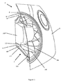
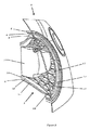
図1乃至図3を参照すると、自動車1には、ライト・アセンブリ2が備えられている。ライト・アセンブリ2は、ボディ・パネル3内の開口部内に設けられている。本実施の形態では、ライト・アセンブリ2は、車両の前方に配置されたヘッドライト・アセンブリである。
Referring to FIGS. 1 to 3, the
ライト・アセンブリ2は、透明なフロント・レンズ4を備えている。フロント・レンズ4は、ポリカーボネート等、どのような素材からなっていてもよい。フロント・レンズ4は、自動車1のボディに取り付けられている。この特定の実施の形態では、装飾的(例:クロム(chrome))リング5がレンズ4の前方を取り囲んでいる。
The
レンズ4の後方には、周辺に、昼間走行用ランプ6が配置されている。昼間走行用ランプ6は、管状の導光リング8の後ろにアレイ状に配置された光源7を含んでいる。導光リング(light guiding ring)8は、注意を引くため、光源7が配置された後方から前方へ光をガイドするように構成されている。この導光リング8は、その長さに沿った損失なしに、リングを通る光の通過を確実にするように設計されている。そして、このような損失を避けるために、その内周面および外周面に反射コーティングを施すことができる。
Behind the
昼間走行用ランプ6の径方向内側には、略円錐台形状の管状反射ハウジング(generally frustoconical tubular reflective housing)9が配置されている。反射ハウジングは、光を反射するように、黒色の高光沢プラスチック(例えばABS(アクリロニトリル・ブタジエン・スチレン)プラスチックまたはPC(ポリカーボネート)でできている。反射ハウジングは、鏡のように反射する(mirrored)必要はないが、異なる色の反射要素(reflective elements)を含むことができる。ライト・アセンブリにしばしば採用される複雑な形状のために、略円錐台形であるが、反射ハウジング9の頂部は外側に向かってフレア状に広がっており、底部は頂部と比較すると真っ直ぐであり、底部は頂部よりも長い。略円錐台形状の管状反射ハウジング9の前方は、部分円筒形領域で終わっている。開口部は、管状の反射ハウジング9の後部に設けられている。
A generally frustoconical tubular reflective housing 9 is arranged inside the
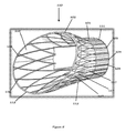
反射ハウジング9内には、ハウジングに隣接し、且つ、ハウジングによって囲まれた、管状光ガイド10が配置されている。管状光ガイド10は、PMMAで形成されており、管状光ガイド10の形状も略円錐台形状である。管状光ガイド10は、反射ハウジング9の形状にしたがって、後方の開口部から前方のレンズ4に向かって延びている。
A tubular
長さに沿って損失を最小限にして光を後方から前方に導くことを目的とする昼間走行用ランプ6の光ガイド・リングとは対照的に、管状光ガイド10は意図的にその長さに沿って光を放射するように形成されている。
In contrast to the light guide ring of the
この目的のために、管状光ガイド10の後方部には、対応する光源12から光を受ける環状後部面(annular rear surface)11を備えている。光源12は、環状後部面11に光を向けるように配置されたアレイの複数のLEDから形成されている。他方、管状光ガイド10の前面は、縁部13に向かって先細る(tapers)ようになっている。
For this purpose, the rear part of the tubular
環状後部面11上には、光源12から受けた光を拡散する複数のファセットが設けられている。
A plurality of facets for diffusing light received from the
管状光ガイド10の長さに沿って、管状光ガイド10の径方向内面14及び径方向外面15には、光を反射し、管状光ガイド10の長さに沿って光を放射する複数のフォーメーションが形成されている。特に、径方向内面14には、光ガイドを後方近くから前方に向かって斜めに横切って延びる一連の十字交差溝(criss-crossing grooves)16が設けられている。
A plurality of formations that reflect light along the length of the tubular
一方、図2に最もよく示されている径方向外側の表面には、複数のファセット17が設けられている。複数のファセット17は、適切に複数の溝16の裏(behind)に並び、カット・ガラス/クリスタルのような外観を与える複数のピラミッド形フォーメーションを形成する鋭い角を有している。
On the other hand, a plurality of
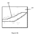
管状光ガイド10は、図4a及び図4bを参照して概略的に示される2ショット射出成形プロセスによって、青色着色ポリカーボネートから形成されている。図4bに示されているように、第1の金型18は、光ガイド本体の形状のチャンバ19内に溶融プラスチック(molten plastic)を収容する。金型は光ガイドに複数の溝16を形成する複数の突起20を有するが、チャンバの反対側(外側)の面はピラミッド部分の形状を含まない。その代わり、第1の射出成形ステップで形成される本体は、比較的均一な形状を有している。これによって、フォーメーションの反対側の面を冷却する際に生じる可能性のある沈下または変形を防止することができる。
The tubular
第1のステップで本体が形成されると、図4bに示す第2の金型21が光ガイド本体を受ける。第2の金型21の内面は、光ガイド本体の内面と正確に一致するが、金型の反対面は、ピラミッド形フォーメーションに対応する凹部22を有する余分な空間を含む。このようにして、溶融プラスチックを追加の空間に注入し、凹部が充填され、ピラミッド形フォーメーションを形成する。これらの部品の深さは様々であるが、溶融プラスチックがすでに成形された本体に付着するため、沈み込みがなく、ファセット上に鋭い角を形成することができ、最終モールド(final mould)が形成される際に接合線(join line)は現れない。このことによって、特に後ろから照明された場合、カット・ガラス/クリスタルのように見えるようになる。
When the main body is formed in the first step, the
管状光ガイド10の径方向内側には、ヘッドライト用のメイン・ヘッドライト・ガイド23が設けられており、その後方部には、複数のLEDのマトリックス24が配置されている。複数のLEDのマトリックス23は、マトリクス内の異なる複数のLEDを点灯させて、ヘッドライト・ガイド23の前方から出る光の量および方向を変えることができるように配置されている。しかしながら、リング6と同様、ヘッドライト・ガイド23は、ガイド23の後方から入る光が前方を通って出て、長さに沿って失われないように意図的に形成されている。これは、全内部反射(total internal reflection)を達成するために、メイン・ヘッドライト・ガイド23の光学特性を調整することによって達成することができる。
A
使用時には、本発明のライト・アセンブリは、ライトのスイッチをオンにする等の手動操作による、または、受光センサ等からの自動のセンサ応答(automatic, sensory response)による車両3内の車載コンピュータ(図示せず)からの信号に対する応答として、複数のLEDのマトリックス24を点灯させることによって、ヘッドライトとして作動する。同様に、昼間走行用ランプ6は、車載コンピュータから受信した信号に対する応答として点灯する。信号は、手動によってもよく、または、使用者からドアロック解除信号(door-unlock signal)を受信する、若しくは、イグニション(ignition)内で鍵を回すことの自動応答によってもよい。照明されるマトリックス24内のLEDの数、すなわち、ヘッドライト・ガイド23を出る光の強度は、入力に応じて変化させることができる。したがって、このヘッドライトは、メイン−ビーム機能及びディップ・ビーム機能の両方を有することができる。
In use, the light assembly of the present invention is a vehicle-mounted computer (see FIG. 3) in the
光ガイド10を照明するために照射される光源12内のLEDの数も、変化させることができ、ゆえに、強度も変化させることができる。本発明の方法では、これは、光ガイド10の長さに沿った光の動的な動きの光学的効果(optical effect)を得るために行われる。したがって、遠隔制御(remote control)からのロック解除信号または警報信号を受信したことに基づく車載コンピュータからの信号に応じて、ウェルカム・シーケンスを実行することができる。ウェルカム・シーケンスは、最初は光源内の比較的少数のLEDを照射させ光強度を低くする。これは、光源12から放射される光の大部分が、光源12が配置されている後方近くの光ガイド10の内面内の溝を通って出ることを意味している。徐々に、例えば、3秒〜10秒の間に、照明するLEDの数及び光強度を増加させると、運転者を歓迎して、光がゆっくり動的に前方に向かって、また、外に向かって動くように見える。全てのLEDが照明した状態になると、昼間走行用ランプ6を照明し、管状光ガイド10の後方に向かって内側にフェード・バックする(fading back)効果を生じさせるため、光源12からの光の強度を0にまで減少してもよい。
The number of LEDs in the
カット・ガラス/クリスタルの外観と組み合わされることで、この効果は著しく三次元的であり、引っ込められる前に握手のために手を伸ばす、または、運転者を歓迎するあいさつ(bow)を呼び起こす。 Combined with the cut glass / crystal appearance, this effect is remarkably three-dimensional and evokes a bow that reaches for a handshake before being retracted or welcomes the driver.
代替モードでは、自動車がオフになるまで、複数のLEDは点灯したままであってもよく、自動車がスイッチ・オフになった時点で、昼間走行用ランプ6をスイッチ・オフにしてもよい。続いて、運転者または乗客が自動車を離れるのに十分な時間(例えば、10秒から3分)において、光源12によって照明される光を徐々に(例えば、3〜10秒にわたって)減少させ、自動車から降りる(withdrawal)効果を生じさせるようにしてもよい。
In the alternative mode, the plurality of LEDs may remain lit until the vehicle is turned off, and the
光源12から出力され、管状光ガイド10を通る光は、駐車ライトとしても作用する。したがって、自動車がスイッチ・オフになっているが、駐車ライトが選択された状態の場合には、光を徐々に減少させるのではなく、光源12によって光が放射され続け、ヘッドランプ内でクリスタル効果が示される。
The light output from the
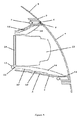
図5に示した本発明のライト・アセンブリ用の光ガイド110の第2の実施の形態は、第1の実施の形態と似ており、同様の反射ハウジング(図示せず)内に収納される。管状光ガイド110も、略円錐台形状であり、反射ハウジングの形状に従って、後方の開口部から前方のレンズ4に向かって延びている。しかしながら、光ガイド110の後部101のより実質的な部分は、管状でほぼ一定の直径を有しており、一方で、光ガイド110の全長の約半分だけがフレア部(flared portion)102を構成している。また、管状光ガイド110の前方部は、鋭い縁部113に向かって先細るようになっている。
The second embodiment of the light guide 110 for the light assembly of the present invention shown in FIG. 5 is similar to the first embodiment and is housed in a similar reflective housing (not shown). . The tubular light guide 110 is also substantially frustoconical and extends from the rear opening toward the
管状光ガイド110は、その長さに沿って光を放射するように意図的に形成されている。したがって、管状光ガイド110の後方部には、対応する光源(図示せず)からの光を受ける環状後部面111も設けられている。環状後部面111上には、光源から受け取った光を拡散させるための複数のファセット103が設けられている。
The tubular light guide 110 is intentionally formed to emit light along its length. Therefore, an annular
管状光ガイド110の長さに沿って、管状光ガイド110の径方向内面114及び径方向外面115には、光を反射し、管状光ガイド110の長さに沿って光を放射する複数のフォーメーションが形成されている。特に、径方向内面114には、V字型の断面を有し、フレア部102が管状部101と交差する領域から、前方の鋭い斜面となった縁部(sharp bevelled edge)113まで、光ガイドを横切って斜めに延びる一連の十字交差溝116が設けられている。
A plurality of formations that reflect light onto the radially inner surface 114 and radially
径方向外面には、また、鋭い角を有する複数のファセット117が設けられている。複数のファセット117は、適切に複数の溝16の裏に並び、カット・ガラス/クリスタルのような外観を与える複数のピラミッド形フォーメーションを形成する鋭い角を有している。
A plurality of
上記実施の態様は、例示としてのみ説明されている。添付の請求の範囲に定めたように、本発明の範囲を逸脱することなく、多くの変形例が可能である。 The above embodiments have been described by way of example only. Many variations are possible without departing from the scope of the invention as defined in the appended claims.
Claims (34)
前記ハウジングは、後方部及び前方部を有しており、使用時には、前記ハウジングの前記前方部から光が放射されるようになっており、
前記ライト・アセンブリは、前記後方部から前記前方部に向かって延び、且つ、前記ハウジングによって少なくとも部分的に囲まれた、透明または半透明の光ガイドをさらに有しており、
前記光ガイドは、その後方部で照明され、且つ、その長さの少なくとも一部に沿って光を放射するように構成されているライト・アセンブリ。 A light assembly having a housing, comprising:
The housing has a rear portion and a front portion, and in use, light is emitted from the front portion of the housing.
The light assembly further includes a transparent or translucent light guide extending from the rear portion toward the front portion and at least partially surrounded by the housing;
The light guide is illuminated at its rear and is configured to emit light along at least a portion of its length.
前記光ガイドの他方の表面には、第2のタイプの前記複数のフォーメーションが形成されている請求項1乃至9のいずれか1項に記載のライト・アセンブリ。 The plurality of formations of the first type are formed on one surface of the light guide,
The light assembly according to any one of claims 1 to 9, wherein a second type of the plurality of formations is formed on the other surface of the light guide.
前記他方の表面の前記第2のタイプの前記複数のフォーメーションは、複数のファセットである請求項10に記載のライト・アセンブリ。 The plurality of formations of the first type on the one surface are a plurality of grooves;
The light assembly of claim 10, wherein the plurality of formations of the second type on the other surface are a plurality of facets.
前記光ガイドの前記後方部を照明する光源は、補助光源である請求項15に記載のライト・アセンブリ。 A main light source, and a light source that illuminates the rear part of the light guide,
The light assembly of claim 15, wherein the light source that illuminates the rear portion of the light guide is an auxiliary light source.
前記ライト・アセンブリは、ハウジングと、光ガイドと、光源とを備えており、
前記ハウジングは、後方部及び前方部を有しており、使用時には、前記ハウジングの前記前方部から光が放射されるようになっており、
前記光ガイドは、透明または半透明であり、前記後方部から前記前方部に向かって延び、且つ、前記ハウジングによって少なくとも部分的に囲まれており、
前記光ガイドは、その後方部で照明され、且つ、その長さの少なくとも一部に沿って光を放射するように構成されており、
前記光ガイドの前記後方部には、前記光源が配置されており、
当該方法では、光が前記光ガイドの長さに沿ってゆっくり進むように見えるように、前記光源から供給される光の強度を徐々に強めることを特徴とするライト・アセンブリの作動方法。 A method of operating the light assembly,
The light assembly includes a housing, a light guide, and a light source;
The housing has a rear portion and a front portion, and in use, light is emitted from the front portion of the housing.
The light guide is transparent or translucent, extends from the rear portion toward the front portion, and is at least partially surrounded by the housing;
The light guide is illuminated at its rear and is configured to emit light along at least a portion of its length;
The light source is disposed at the rear portion of the light guide,
The method of operating a light assembly, wherein the intensity of light supplied from the light source is gradually increased so that light appears to travel slowly along the length of the light guide.
前記光の強度を強めるために、点灯させる前記複数の光源の数を増加させる請求項24または25に記載のライト・アセンブリの作動方法。 The light source disposed in the rear portion of the light guide that illuminates the light guide is an array of a plurality of light sources;
26. The method of operating a light assembly according to claim 24 or 25, wherein the number of the plurality of light sources to be lit is increased in order to increase the intensity of the light.
次に別の光源を点灯させ、
次に前記光源から供給される前記光の強度を徐々に弱める請求項28に記載のライト・アセンブリの作動方法。 Gradually increasing the intensity of the light supplied from the light source,
Next, turn on another light source,
29. The method according to claim 28, wherein the light intensity supplied from the light source is gradually reduced.
2段階射出成形プロセスを含み、
前記光ガイドの本体部は、第1の射出成形ステップで形成され、
前記本体部の少なくとも一方の表面上の複数のフォーメーションは、第2の射出成形ステップで形成される光ガイドの形成方法。 A method for forming a light guide according to any one of claims 1 to 24,
Including a two-stage injection molding process,
The light guide body is formed in a first injection molding step,
The light guide forming method, wherein the plurality of formations on at least one surface of the main body are formed in a second injection molding step.
第2のタイプの複数のフォーメーションが、他方の表面に形成される請求項30に記載の光ガイドの形成方法。 A plurality of formations of a first type are formed on one surface;
31. The method of forming a light guide according to claim 30, wherein a plurality of formations of the second type are formed on the other surface.
対向面のファセットは、前記第2の射出成形ステップ形成される請求項31に記載の光ガイドの形成方法。 A plurality of grooves on one surface is formed in the first injection molding step,
32. The method of forming a light guide according to claim 31, wherein facets on the opposing surface are formed in the second injection molding step.
一方の表面に第1のタイプの複数のフォーメーションを有するように、且つ、他方の表面に第2のタイプの複数のフォーメーションを有するように光ガイドを機械加工する車両用ライト・アセンブリの形成方法。 25. A method of forming a vehicle light assembly according to any one of claims 1 to 24, comprising:
A method of forming a light assembly for a vehicle, wherein the light guide is machined to have a plurality of formations of a first type on one surface and a plurality of formations of a second type on the other surface.
Applications Claiming Priority (3)
| Application Number | Priority Date | Filing Date | Title |
|---|---|---|---|
| GB1503233.7 | 2015-02-26 | ||
| GB1503233.7A GB2535758B (en) | 2015-02-26 | 2015-02-26 | Vehicle light assembly and lighting method |
| PCT/GB2016/050435 WO2016135461A2 (en) | 2015-02-26 | 2016-02-22 | Vehicle light assembly and lighting method |
Publications (3)
| Publication Number | Publication Date |
|---|---|
| JP2018506830A true JP2018506830A (en) | 2018-03-08 |
| JP2018506830A5 JP2018506830A5 (en) | 2019-02-07 |
| JP6887384B2 JP6887384B2 (en) | 2021-06-16 |
Family
ID=52876163
Family Applications (1)
| Application Number | Title | Priority Date | Filing Date |
|---|---|---|---|
| JP2017545570A Active JP6887384B2 (en) | 2015-02-26 | 2016-02-22 | Vehicle light assembly and lighting methods |
Country Status (6)
| Country | Link |
|---|---|
| US (1) | US10421388B2 (en) |
| EP (2) | EP4219235B1 (en) |
| JP (1) | JP6887384B2 (en) |
| CN (1) | CN208611801U (en) |
| GB (1) | GB2535758B (en) |
| WO (1) | WO2016135461A2 (en) |
Cited By (1)
| Publication number | Priority date | Publication date | Assignee | Title |
|---|---|---|---|---|
| JP2020024793A (en) * | 2018-08-06 | 2020-02-13 | マツダ株式会社 | Vehicular lighting system |
Families Citing this family (7)
| Publication number | Priority date | Publication date | Assignee | Title |
|---|---|---|---|---|
| US9593820B1 (en) * | 2016-09-28 | 2017-03-14 | Ford Global Technologies, Llc | Vehicle illumination system |
| FR3056680B1 (en) * | 2016-09-29 | 2018-11-09 | Valeo Vision | LIGHTING SYSTEM FOR MOTOR VEHICLE |
| CZ2017773A3 (en) * | 2017-12-01 | 2019-06-12 | Varroc Lighting Systems, s.r.o. | Lighting, in particular a signal light for motor vehicles |
| USD931768S1 (en) * | 2019-06-27 | 2021-09-28 | Bentley Motors Limitd | Radiator grille |
| CN110341580B (en) * | 2019-07-04 | 2024-04-05 | 上汽大众汽车有限公司 | Carpet lamp |
| US11006500B1 (en) * | 2020-01-17 | 2021-05-11 | B/E Aerospace, Inc. | End of life detection system for aircraft anti-collision light |
| CN117570390A (en) * | 2023-11-16 | 2024-02-20 | 南宁燎旺车灯股份有限公司 | A method for improving the resistance of a car light reflector to sunlight concentration and heating and a car light |
Citations (12)
| Publication number | Priority date | Publication date | Assignee | Title |
|---|---|---|---|---|
| JP2005056623A (en) * | 2003-07-31 | 2005-03-03 | Ichikoh Ind Ltd | Vehicle lighting |
| JP2005122946A (en) * | 2003-10-14 | 2005-05-12 | Honda Motor Co Ltd | Vehicle lighting device |
| JP2006509343A (en) * | 2002-12-06 | 2006-03-16 | エスエル エルシーディー カンパニー リミテッド | Vehicle lamp |
| JP2007276396A (en) * | 2006-04-11 | 2007-10-25 | Koito Mfg Co Ltd | Resin lens molding method and resin lens |
| JP2007294260A (en) * | 2006-04-25 | 2007-11-08 | Matsushita Electric Works Ltd | Production lighting system |
| JP2008010227A (en) * | 2006-06-28 | 2008-01-17 | Koito Mfg Co Ltd | Vehicle lighting |
| JP2009087887A (en) * | 2007-10-03 | 2009-04-23 | Colcoat Kk | Vehicle interior lighting device |
| DE102008021902A1 (en) * | 2008-05-02 | 2009-11-05 | Volkswagen Ag | Lighting device for motor vehicle, has light source i.e. LED, illuminating light, and opening whose diameter extends with increased distance from light source, where opening passes in end section with light injecting surface |
| JP2010129311A (en) * | 2008-11-26 | 2010-06-10 | Stanley Electric Co Ltd | Lighting fixture for vehicle |
| JP2012138330A (en) * | 2010-12-28 | 2012-07-19 | Hayashi Engineering Inc | Lighting system |
| WO2013012066A1 (en) * | 2011-07-21 | 2013-01-24 | 京セラ株式会社 | Lighting device, image sensor head and reading device provided with same |
| JP2014139941A (en) * | 2007-08-07 | 2014-07-31 | Rohm Co Ltd | Device for controlling lighting or lighting out of light source |
Family Cites Families (35)
| Publication number | Priority date | Publication date | Assignee | Title |
|---|---|---|---|---|
| FR2472135A1 (en) * | 1979-12-20 | 1981-06-26 | Cibie Projecteurs | PROJECTOR, IN PARTICULAR FOR MOTOR VEHICLES |
| US5709453A (en) * | 1994-08-16 | 1998-01-20 | Krent; Edward D. | Vehicle lighting having remote light source |
| DE19652159B4 (en) * | 1996-12-14 | 2006-05-18 | Automotive Lighting Reutlingen Gmbh | Lighting device for vehicles |
| FR2776251B1 (en) | 1998-02-17 | 2000-05-05 | Renault | SIGNAL LIGHT FOR A MOTOR VEHICLE |
| JP4070880B2 (en) * | 1998-06-12 | 2008-04-02 | 本田技研工業株式会社 | Motorcycle headlights |
| FR2799263B1 (en) * | 1999-09-30 | 2001-12-21 | Valeo Vision | LIGHT-CONDUCTOR PROJECTOR FOR A MOTOR VEHICLE, AND PAIR OF PROJECTORS |
| DE10124370B4 (en) * | 2001-05-18 | 2010-11-18 | Zumtobel Lighting Gmbh | Optical element with total reflection |
| US6789929B1 (en) * | 2002-09-11 | 2004-09-14 | Dj Auto Components Corp. | Lamp structure |
| CN1997922B (en) * | 2004-04-30 | 2011-01-12 | 厄伊莫迪里斯有限公司 | Ultra-thin Lighting Elements |
| JP2005331565A (en) * | 2004-05-18 | 2005-12-02 | Seiko Epson Corp | LIGHTING DEVICE, LIQUID CRYSTAL DISPLAY DEVICE, AND ELECTRONIC DEVICE |
| US7097336B2 (en) * | 2004-05-28 | 2006-08-29 | Yu-Chu Lin | Auxiliary light ring device for a vehicular light |
| US7055999B2 (en) * | 2004-09-10 | 2006-06-06 | Yu-Chu Lin | Auxiliary light ring device for a vehicular light |
| DE102006016656A1 (en) | 2006-04-08 | 2007-10-11 | Hella Kgaa Hueck & Co. | Lighting system for vehicles has source of light and light guide made of one plastic material and light decoupling components are made of other plastic material |
| CZ307329B6 (en) * | 2006-05-15 | 2018-06-13 | Varroc Lighting Systems, s.r.o. | A lighting device for a motor vehicle, comprising a planar lightguide |
| JP5210061B2 (en) * | 2008-07-10 | 2013-06-12 | 株式会社小糸製作所 | Lamp |
| EP2440840A4 (en) * | 2009-06-12 | 2016-08-24 | Federal Mogul Corp | Distributed lighting assembly |
| JP2011076858A (en) * | 2009-09-30 | 2011-04-14 | Koito Mfg Co Ltd | Vehicular lighting fixture |
| FR2956720B1 (en) * | 2010-02-19 | 2013-03-15 | Valeo Vision | OPTICAL SYSTEM OF A MOTOR VEHICLE |
| FR2962704B1 (en) * | 2010-07-16 | 2013-05-17 | Valeo Vision | DEVICE FOR LIGHTING AND / OR SIGNALING A MOTOR VEHICLE |
| CN101922632B (en) * | 2010-07-22 | 2012-12-19 | 鸿富锦精密工业(深圳)有限公司 | LED lighting device |
| JP2012064535A (en) * | 2010-09-17 | 2012-03-29 | Koito Mfg Co Ltd | Lamp fitting for vehicle |
| US8465185B2 (en) * | 2011-01-05 | 2013-06-18 | Ford Global Technologies, Llc | Vehicle exterior lamp |
| JP5749576B2 (en) * | 2011-06-07 | 2015-07-15 | 株式会社小糸製作所 | Vehicle lighting |
| DE102011051541B4 (en) | 2011-07-04 | 2023-06-29 | HELLA GmbH & Co. KGaA | Lighting device for vehicles |
| JP5753012B2 (en) * | 2011-07-05 | 2015-07-22 | 株式会社小糸製作所 | Vehicle lighting |
| JP2013048036A (en) | 2011-08-29 | 2013-03-07 | Toyoda Gosei Co Ltd | Lamp fitting for vehicle |
| DE102011112716A1 (en) | 2011-09-07 | 2013-03-07 | Audi Ag | Method for operating a headlamp of a motor vehicle |
| JP2013056603A (en) * | 2011-09-08 | 2013-03-28 | Yamaha Motor Co Ltd | Saddle-riding type vehicle and light guide used in the same |
| DE102011083363A1 (en) * | 2011-09-26 | 2013-03-28 | Ford Global Technologies, Llc | The vehicle lighting device |
| DE102011119231A1 (en) * | 2011-11-23 | 2013-05-23 | Audi Ag | Motor vehicle light, motor vehicle and method for operating a motor vehicle light |
| DE102012221389B4 (en) * | 2012-11-22 | 2019-08-22 | Automotive Lighting Reutlingen Gmbh | Motor vehicle light with a light guide and a visible through the light guide aperture |
| DE102012112151B4 (en) * | 2012-12-12 | 2023-11-16 | HELLA GmbH & Co. KGaA | Motor vehicle taillight with at least one taillight function, a flashing light function and a brake light function, which includes a first and at least one second light guide |
| DE102013104174B4 (en) * | 2013-04-25 | 2022-09-15 | HELLA GmbH & Co. KGaA | Lighting device for vehicles with an elongate light guide which is illuminated in a locally variable manner in its longitudinal direction via its curved diffusing surface |
| FR3008775B1 (en) | 2013-07-22 | 2017-12-29 | Renault Sas | LIGHTING SYSTEM, IN PARTICULAR FOR A MOTOR VEHICLE LIGHTING BODY, WITH A LUMINOUS ELEMENT DISPENSING FROM THE LIGHT SOURCE |
| EP2980472B1 (en) * | 2014-07-28 | 2018-01-17 | OSRAM GmbH | A lighting device and corresponding method |
-
2015
- 2015-02-26 GB GB1503233.7A patent/GB2535758B/en active Active
-
2016
- 2016-02-22 EP EP23172412.1A patent/EP4219235B1/en active Active
- 2016-02-22 WO PCT/GB2016/050435 patent/WO2016135461A2/en not_active Ceased
- 2016-02-22 JP JP2017545570A patent/JP6887384B2/en active Active
- 2016-02-22 EP EP16712978.2A patent/EP3274623B1/en active Active
- 2016-02-22 CN CN201690000514.XU patent/CN208611801U/en not_active Expired - Lifetime
- 2016-02-22 US US15/552,324 patent/US10421388B2/en active Active
Patent Citations (12)
| Publication number | Priority date | Publication date | Assignee | Title |
|---|---|---|---|---|
| JP2006509343A (en) * | 2002-12-06 | 2006-03-16 | エスエル エルシーディー カンパニー リミテッド | Vehicle lamp |
| JP2005056623A (en) * | 2003-07-31 | 2005-03-03 | Ichikoh Ind Ltd | Vehicle lighting |
| JP2005122946A (en) * | 2003-10-14 | 2005-05-12 | Honda Motor Co Ltd | Vehicle lighting device |
| JP2007276396A (en) * | 2006-04-11 | 2007-10-25 | Koito Mfg Co Ltd | Resin lens molding method and resin lens |
| JP2007294260A (en) * | 2006-04-25 | 2007-11-08 | Matsushita Electric Works Ltd | Production lighting system |
| JP2008010227A (en) * | 2006-06-28 | 2008-01-17 | Koito Mfg Co Ltd | Vehicle lighting |
| JP2014139941A (en) * | 2007-08-07 | 2014-07-31 | Rohm Co Ltd | Device for controlling lighting or lighting out of light source |
| JP2009087887A (en) * | 2007-10-03 | 2009-04-23 | Colcoat Kk | Vehicle interior lighting device |
| DE102008021902A1 (en) * | 2008-05-02 | 2009-11-05 | Volkswagen Ag | Lighting device for motor vehicle, has light source i.e. LED, illuminating light, and opening whose diameter extends with increased distance from light source, where opening passes in end section with light injecting surface |
| JP2010129311A (en) * | 2008-11-26 | 2010-06-10 | Stanley Electric Co Ltd | Lighting fixture for vehicle |
| JP2012138330A (en) * | 2010-12-28 | 2012-07-19 | Hayashi Engineering Inc | Lighting system |
| WO2013012066A1 (en) * | 2011-07-21 | 2013-01-24 | 京セラ株式会社 | Lighting device, image sensor head and reading device provided with same |
Cited By (2)
| Publication number | Priority date | Publication date | Assignee | Title |
|---|---|---|---|---|
| JP2020024793A (en) * | 2018-08-06 | 2020-02-13 | マツダ株式会社 | Vehicular lighting system |
| JP7115126B2 (en) | 2018-08-06 | 2022-08-09 | マツダ株式会社 | Vehicle lighting device |
Also Published As
| Publication number | Publication date |
|---|---|
| EP3274623A2 (en) | 2018-01-31 |
| US10421388B2 (en) | 2019-09-24 |
| EP4219235A1 (en) | 2023-08-02 |
| US20180236926A1 (en) | 2018-08-23 |
| EP3274623B1 (en) | 2023-05-17 |
| CN208611801U (en) | 2019-03-19 |
| GB2535758B (en) | 2018-09-05 |
| GB2535758A (en) | 2016-08-31 |
| JP6887384B2 (en) | 2021-06-16 |
| GB201503233D0 (en) | 2015-04-15 |
| WO2016135461A2 (en) | 2016-09-01 |
| EP4219235B1 (en) | 2025-07-09 |
| WO2016135461A3 (en) | 2016-10-27 |
Similar Documents
| Publication | Publication Date | Title |
|---|---|---|
| JP6887384B2 (en) | Vehicle light assembly and lighting methods | |
| CN103635741B (en) | Car light element | |
| CN202147628U (en) | Vehicle illuminating system and panel for vehicle head lamp | |
| US6746634B2 (en) | Vehicular lamp and injection mold and manufacturing method for lamp body of vehicular lamp | |
| US10724729B2 (en) | Vehicle lighting assemblies and modules | |
| US9688034B2 (en) | Automotive light assembly with inner lens for combined daytime running light and position light functions | |
| US10207632B2 (en) | Vehicle body element comprising a translucent body and method for producing such a body | |
| JP2018506830A5 (en) | ||
| CN112902100A (en) | Light bar for external lighting assembly | |
| EP2481635B1 (en) | Motor vehicle light | |
| JP2023052906A (en) | Light-emitting devices for road lighting, signaling or interior lighting | |
| KR101622095B1 (en) | Lamp apparatus for an automobile | |
| CN213810442U (en) | Novel optical structure with modeling pattern characteristics for vehicle lamp | |
| US11027642B2 (en) | Bezel apparatus for use with vehicle lamps and related methods | |
| CN2746260Y (en) | Car light structure with aperture | |
| US12624817B2 (en) | Method and apparatus for a silhouette design vehicle light | |
| CN221171909U (en) | Car light pattern with attractive lighting effect and car light | |
| CN223525012U (en) | Soft slow reflection car light structure | |
| CN207501071U (en) | A kind of automobile tail light of the multi-level effect of depth | |
| CN214249437U (en) | Front lamp mask structure integrated with light guide strip | |
| CN220707135U (en) | Light guide structure, lighting device, car light assembly and car thereof | |
| CN210373272U (en) | Combined car tail light with retro reflector, LED rear fog light | |
| TWM268228U (en) | Haloed vehicle light | |
| CN106195844B (en) | A kind of automotive trim lamp | |
| IT201600114529A1 (en) | AUTOMOTIVE HEADLIGHT |
Legal Events
| Date | Code | Title | Description |
|---|---|---|---|
| A521 | Request for written amendment filed |
Free format text: JAPANESE INTERMEDIATE CODE: A523 Effective date: 20181221 |
|
| A621 | Written request for application examination |
Free format text: JAPANESE INTERMEDIATE CODE: A621 Effective date: 20181221 |
|
| A131 | Notification of reasons for refusal |
Free format text: JAPANESE INTERMEDIATE CODE: A131 Effective date: 20191119 |
|
| A977 | Report on retrieval |
Free format text: JAPANESE INTERMEDIATE CODE: A971007 Effective date: 20191120 |
|
| A601 | Written request for extension of time |
Free format text: JAPANESE INTERMEDIATE CODE: A601 Effective date: 20200214 |
|
| A521 | Request for written amendment filed |
Free format text: JAPANESE INTERMEDIATE CODE: A523 Effective date: 20200415 |
|
| A131 | Notification of reasons for refusal |
Free format text: JAPANESE INTERMEDIATE CODE: A131 Effective date: 20200929 |
|
| A521 | Request for written amendment filed |
Free format text: JAPANESE INTERMEDIATE CODE: A523 Effective date: 20201215 |
|
| TRDD | Decision of grant or rejection written | ||
| A01 | Written decision to grant a patent or to grant a registration (utility model) |
Free format text: JAPANESE INTERMEDIATE CODE: A01 Effective date: 20210420 |
|
| A61 | First payment of annual fees (during grant procedure) |
Free format text: JAPANESE INTERMEDIATE CODE: A61 Effective date: 20210518 |
|
| R150 | Certificate of patent or registration of utility model |
Ref document number: 6887384 Country of ref document: JP Free format text: JAPANESE INTERMEDIATE CODE: R150 |
|
| R250 | Receipt of annual fees |
Free format text: JAPANESE INTERMEDIATE CODE: R250 |
|
| R250 | Receipt of annual fees |
Free format text: JAPANESE INTERMEDIATE CODE: R250 |