JP2018511237A - Content adaptive B picture pattern video encoding - Google Patents
Content adaptive B picture pattern video encoding Download PDFInfo
- Publication number
- JP2018511237A JP2018511237A JP2017546602A JP2017546602A JP2018511237A JP 2018511237 A JP2018511237 A JP 2018511237A JP 2017546602 A JP2017546602 A JP 2017546602A JP 2017546602 A JP2017546602 A JP 2017546602A JP 2018511237 A JP2018511237 A JP 2018511237A
- Authority
- JP
- Japan
- Prior art keywords
- gop
- decomposition
- cost
- picture
- consecutive pictures
- Prior art date
- Legal status (The legal status is an assumption and is not a legal conclusion. Google has not performed a legal analysis and makes no representation as to the accuracy of the status listed.)
- Withdrawn
Links
Images


Classifications
-
- H—ELECTRICITY
- H04—ELECTRIC COMMUNICATION TECHNIQUE
- H04N—PICTORIAL COMMUNICATION, e.g. TELEVISION
- H04N19/00—Methods or arrangements for coding, decoding, compressing or decompressing digital video signals
- H04N19/10—Methods or arrangements for coding, decoding, compressing or decompressing digital video signals using adaptive coding
- H04N19/134—Methods or arrangements for coding, decoding, compressing or decompressing digital video signals using adaptive coding characterised by the element, parameter or criterion affecting or controlling the adaptive coding
- H04N19/136—Incoming video signal characteristics or properties
-
- H—ELECTRICITY
- H04—ELECTRIC COMMUNICATION TECHNIQUE
- H04N—PICTORIAL COMMUNICATION, e.g. TELEVISION
- H04N19/00—Methods or arrangements for coding, decoding, compressing or decompressing digital video signals
- H04N19/10—Methods or arrangements for coding, decoding, compressing or decompressing digital video signals using adaptive coding
- H04N19/102—Methods or arrangements for coding, decoding, compressing or decompressing digital video signals using adaptive coding characterised by the element, parameter or selection affected or controlled by the adaptive coding
- H04N19/103—Selection of coding mode or of prediction mode
- H04N19/114—Adapting the group of pictures [GOP] structure, e.g. number of B-frames between two anchor frames
-
- H—ELECTRICITY
- H04—ELECTRIC COMMUNICATION TECHNIQUE
- H04N—PICTORIAL COMMUNICATION, e.g. TELEVISION
- H04N19/00—Methods or arrangements for coding, decoding, compressing or decompressing digital video signals
- H04N19/10—Methods or arrangements for coding, decoding, compressing or decompressing digital video signals using adaptive coding
- H04N19/134—Methods or arrangements for coding, decoding, compressing or decompressing digital video signals using adaptive coding characterised by the element, parameter or criterion affecting or controlling the adaptive coding
- H04N19/146—Data rate or code amount at the encoder output
- H04N19/147—Data rate or code amount at the encoder output according to rate distortion criteria
-
- H—ELECTRICITY
- H04—ELECTRIC COMMUNICATION TECHNIQUE
- H04N—PICTORIAL COMMUNICATION, e.g. TELEVISION
- H04N19/00—Methods or arrangements for coding, decoding, compressing or decompressing digital video signals
- H04N19/10—Methods or arrangements for coding, decoding, compressing or decompressing digital video signals using adaptive coding
- H04N19/169—Methods or arrangements for coding, decoding, compressing or decompressing digital video signals using adaptive coding characterised by the coding unit, i.e. the structural portion or semantic portion of the video signal being the object or the subject of the adaptive coding
- H04N19/177—Methods or arrangements for coding, decoding, compressing or decompressing digital video signals using adaptive coding characterised by the coding unit, i.e. the structural portion or semantic portion of the video signal being the object or the subject of the adaptive coding the unit being a group of pictures [GOP]
-
- H—ELECTRICITY
- H04—ELECTRIC COMMUNICATION TECHNIQUE
- H04N—PICTORIAL COMMUNICATION, e.g. TELEVISION
- H04N19/00—Methods or arrangements for coding, decoding, compressing or decompressing digital video signals
- H04N19/10—Methods or arrangements for coding, decoding, compressing or decompressing digital video signals using adaptive coding
- H04N19/189—Methods or arrangements for coding, decoding, compressing or decompressing digital video signals using adaptive coding characterised by the adaptation method, adaptation tool or adaptation type used for the adaptive coding
- H04N19/19—Methods or arrangements for coding, decoding, compressing or decompressing digital video signals using adaptive coding characterised by the adaptation method, adaptation tool or adaptation type used for the adaptive coding using optimisation based on Lagrange multipliers
-
- H—ELECTRICITY
- H04—ELECTRIC COMMUNICATION TECHNIQUE
- H04N—PICTORIAL COMMUNICATION, e.g. TELEVISION
- H04N19/00—Methods or arrangements for coding, decoding, compressing or decompressing digital video signals
- H04N19/42—Methods or arrangements for coding, decoding, compressing or decompressing digital video signals characterised by implementation details or hardware specially adapted for video compression or decompression, e.g. dedicated software implementation
- H04N19/423—Methods or arrangements for coding, decoding, compressing or decompressing digital video signals characterised by implementation details or hardware specially adapted for video compression or decompression, e.g. dedicated software implementation characterised by memory arrangements
-
- H—ELECTRICITY
- H04—ELECTRIC COMMUNICATION TECHNIQUE
- H04N—PICTORIAL COMMUNICATION, e.g. TELEVISION
- H04N19/00—Methods or arrangements for coding, decoding, compressing or decompressing digital video signals
- H04N19/50—Methods or arrangements for coding, decoding, compressing or decompressing digital video signals using predictive coding
-
- H—ELECTRICITY
- H04—ELECTRIC COMMUNICATION TECHNIQUE
- H04N—PICTORIAL COMMUNICATION, e.g. TELEVISION
- H04N19/00—Methods or arrangements for coding, decoding, compressing or decompressing digital video signals
- H04N19/50—Methods or arrangements for coding, decoding, compressing or decompressing digital video signals using predictive coding
- H04N19/503—Methods or arrangements for coding, decoding, compressing or decompressing digital video signals using predictive coding involving temporal prediction
- H04N19/51—Motion estimation or motion compensation
- H04N19/573—Motion compensation with multiple frame prediction using two or more reference frames in a given prediction direction
-
- H—ELECTRICITY
- H04—ELECTRIC COMMUNICATION TECHNIQUE
- H04N—PICTORIAL COMMUNICATION, e.g. TELEVISION
- H04N19/00—Methods or arrangements for coding, decoding, compressing or decompressing digital video signals
- H04N19/50—Methods or arrangements for coding, decoding, compressing or decompressing digital video signals using predictive coding
- H04N19/503—Methods or arrangements for coding, decoding, compressing or decompressing digital video signals using predictive coding involving temporal prediction
- H04N19/51—Motion estimation or motion compensation
- H04N19/577—Motion compensation with bidirectional frame interpolation, i.e. using B-pictures
Landscapes
- Engineering & Computer Science (AREA)
- Multimedia (AREA)
- Signal Processing (AREA)
- Compression Or Coding Systems Of Tv Signals (AREA)
Abstract
コンテンツ適応型のビデオエンコーディングの方法が開示される。エンコーディング方法は、エンコーディングを最適化するように自動的に調整され、エンコーディングされるピクチャのコンテンツに応じて調整される。方法を実行するシステム、及び、方法の命令を記憶したコンピュータ可読記憶媒体も開示される。【選択図】図3AA content adaptive video encoding method is disclosed. The encoding method is automatically adjusted to optimize the encoding and adjusted according to the content of the picture being encoded. A system for performing the method and a computer-readable storage medium storing the instructions for the method are also disclosed. [Selection] Figure 3A
Description
(関連出願の相互参照)
本願は、2015年3月4日に出願された米国仮特許出願第14/638,503号の利益を主張し、その内容が参考として本明細書に組み込まれる。
(Cross-reference of related applications)
This application claims the benefit of US Provisional Patent Application No. 14 / 638,503, filed Mar. 4, 2015, the contents of which are incorporated herein by reference.
本発明は、概してビデオに関し、特にデジタルビデオ処理に関する。 The present invention relates generally to video, and more particularly to digital video processing.
ビデオエンコーダは、空間的及び時間的な冗長性を低減することによって、ビデオピクチャ又はフレームのシーケンスを圧縮する。これは、空間的及び/又は時間的な領域で予測処理を実行することによって行われる。予測処理がカレントピクチャの情報のみを使用する場合には、イントラ予測と呼ばれ、符号化(エンコーディング)されるピクチャはIピクチャと呼ばれる。一方、予測処理が、異なるピクチャ間の相関を使用する場合には、インター予測と呼ばれる。殆どのエンコーダは、P(predicted)予測及びB(bidirectional)予測という2種類のインター予測をサポートしている。主な違いは、P予測が、1つの予測ブロックのみに基づいてカレントブロックの値を予測し、B予測は、以前に符号化された2つのブロックに基づいてカレントブロックの補間ベースの予測を可能にすることである。 Video encoders compress a sequence of video pictures or frames by reducing spatial and temporal redundancy. This is done by performing the prediction process in the spatial and / or temporal domain. When the prediction process uses only the information of the current picture, it is called intra prediction, and a picture to be encoded (encoded) is called an I picture. On the other hand, when the prediction process uses correlation between different pictures, it is called inter prediction. Most encoders support two types of inter prediction: P (predicted) prediction and B (bidirectional) prediction. The main difference is that P prediction predicts the value of the current block based on only one prediction block, and B prediction allows interpolation-based prediction of the current block based on two previously encoded blocks Is to do.
マクロブロック(MB)は、16×16ピクセルのブロックである。Iピクチャ内の全てのマクロブロックはイントラ予測されるが、Pピクチャ内のMBは、Pインター又はイントラ予測の何れか(より効率的な何れか)であり得る。最後に、BピクチャのMBは、Bインター、Pインター又はイントラ予測の何れかにすることができる。 A macroblock (MB) is a 16 × 16 pixel block. All macroblocks in an I picture are intra predicted, but MBs in a P picture can be either P inter or intra predicted (either more efficient). Finally, the B picture MB can be either B inter, P inter or intra prediction.
ビデオ圧縮では、ピクチャグループ(GOP)は、イントラピクチャ及びインターピクチャが配置される順序を指定する。GOPは、符号化されたビデオストリーム内で連続するピクチャのグループである。符号化されたビデオストリームの各々は、連続するGOPで構成されている。 In video compression, a picture group (GOP) specifies the order in which intra pictures and inter pictures are arranged. A GOP is a group of pictures that are consecutive in an encoded video stream. Each encoded video stream is composed of continuous GOPs.
ピクチャは、予測構造(prediction structure)に基づいて符号化される。予測構造は、GOP内の所定のピクチャを符号化するためにGOP内の何れのピクチャが使用されるか、及び、I、P又はBの各予測タイプを記述する。既存の符号化方法は、ピクチャコンテンツの性質を考慮することなく、既定の予測構造を使用する。これは、最適ではない符号化に繋がることがある。 A picture is encoded based on a prediction structure. The prediction structure describes which picture in the GOP is used to encode a given picture in the GOP and each I, P or B prediction type. Existing coding methods use a predefined prediction structure without considering the nature of the picture content. This can lead to non-optimal encoding.
コンテンツ適応型のビデオエンコーディングの方法が開示される。すなわち、エンコーディングの方法は、エンコーディングを最適化するために、エンコーディング処理の1つ以上の態様を自動的に調整する。この調整は、エンコーディングされるピクチャのコンテンツに依存する。一実施形態では、調整される態様は、ピクチャグループのサイズ及び予測構造であってもよい。方法を実行するためのシステム、及び、当該方法の命令を記憶するための非一時的(non-transitory)なコンピュータ可読記憶媒体も開示される。 A content adaptive video encoding method is disclosed. That is, the encoding method automatically adjusts one or more aspects of the encoding process to optimize the encoding. This adjustment depends on the content of the picture being encoded. In one embodiment, the adjusted aspect may be the size of the picture group and the prediction structure. A system for performing the method and a non-transitory computer-readable storage medium for storing the instructions of the method are also disclosed.
添付図面と併せて例として与えられる以下の説明から、より詳細な理解を得ることができる。 A more detailed understanding may be had from the following description, given by way of example in conjunction with the accompanying drawings wherein:
コンテンツ適応型ビデオエンコーディングの方法及びシステムを、ここで詳細に説明する。この方法は、ピクチャグループ(GOP)及び予測構造を選択して、動画像を構成するピクチャ又はフレームのエンコーディングを最適化することを含む。エンコーディングを最適化するために使用される最適化メトリックは、レート歪み(RD)コストである。これらの用語は以下で説明される。 The content adaptive video encoding method and system will now be described in detail. The method includes selecting a picture group (GOP) and a prediction structure to optimize the encoding of pictures or frames that make up a moving picture. The optimization metric used to optimize the encoding is rate distortion (RD) cost. These terms are explained below.
レート歪みコストは、ピクチャ又はピクチャグループをエンコーディングするために必要なビットレート又はビット数と、エンコーディングによって導入される画像歪みとの組み合わせを指す。一般に、ピクチャをエンコーディングするために使用されるビットの数を減らすことは、より多くの歪みをもたらす傾向があり、エンコーディングされたピクチャ内の情報がより少なくなる。したがって、レート及び歪みの組み合わせは、エンコーディング最適化の合理的なメトリックに関して必要となる。歪みを決定する方法は、本明細書において後述する。 Rate distortion cost refers to the combination of the bit rate or number of bits required to encode a picture or group of pictures and the image distortion introduced by the encoding. In general, reducing the number of bits used to encode a picture tends to result in more distortion and less information in the encoded picture. Thus, a combination of rate and distortion is needed for a reasonable metric for encoding optimization. A method for determining distortion will be described later in this specification.
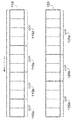
図1は、限定的に考えらえるものではないが、GOP及びGOP分解の例を示す図である。ビデオシーケンス内で連続する12のピクチャが示されている。連続する12のピクチャは、2つの別個のGOP分解110,120に分解されて示される。分解110において、12のピクチャは、2つのピクチャ、3つのピクチャ、3つのピクチャ、及び、4つのピクチャの各々のサイズを有する4つのGOP115a〜115dに分解されて示される。分解120において、同じ12のピクチャは、4つのピクチャ、3つのピクチャ、及び、5つのピクチャの各々のサイズを有する3つのGOP125a〜125cに分解されている。GOPの数、及び、各GOP内のピクチャの数は固定されていない。
FIG. 1 is a diagram showing an example of GOP and GOP decomposition, although not limited to this. Twelve consecutive pictures in the video sequence are shown. Twelve consecutive pictures are shown broken down into two separate GOP decompositions 110,120. In
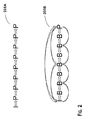
図2は、限定的に考えられるものではないが、9つのピクチャを含む例示的なGOPに適用されている、2つの異なる予測構造205A,205Bの例を示す図である。205Aでは、最初のピクチャのみがIピクチャとしてエンコーディングされ、他の全てのピクチャがPピクチャとしてエンコーディングされており、各ピクチャは1つ前のピクチャを参照する。予測構造205Aは、例えばエンコーディングされているピクチャが急速に動くオブジェクトを含む場合、ほぼ最適なエンコーディングを提供することができるが、ピクチャがゆっくり動くオブジェクトを含む場合には、準最適符号化(suboptimal encoding)を提供することができる。
FIG. 2 is an illustration of two
一方、ピクチャが、例えば、ゆっくり動くオブジェクトを含むことにより、高い時間的相関性を示す場合には、予測構造205Bは、205Aよりも最適により近いエンコーディングを提供することができる。予測構造205Bは、Bフレームを使用しており、階層B構造(HBS)と呼ばれる。したがって、RDコストによって測定される、最適なエンコーディングをもたらす予測構造は、エンコーディングされるピクチャの内容に依存する。 On the other hand, if the picture shows a high temporal correlation, for example by including slowly moving objects, the prediction structure 205B can provide an encoding that is closer to optimal than 205A. Prediction structure 205B uses B frames and is referred to as a hierarchical B structure (HBS). Thus, the prediction structure that results in the optimal encoding, as measured by the RD cost, depends on the content of the picture being encoded.
したがって、その予測構造をピクチャのコンテンツに適応させるエンコーディング方法は、固定された予測構造を有するエンコーディング方法よりも優れたエンコーディング最適化を提供することができる。また、HBSを使用するコンテンツ適応型ビデオエンコーディング方法は、より良いエンコーディングを提供することができる。 Therefore, an encoding method that adapts the prediction structure to the content of a picture can provide better encoding optimization than an encoding method that has a fixed prediction structure. Also, the content adaptive video encoding method using HBS can provide better encoding.
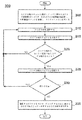
図3A及び図3Bは、コンテンツ適応型ビデオエンコーディング方法300の実施形態を示す図である。図3Aは、方法300の概要を示す図であり、図3Bは、図3Aの315においてGOP分解のRDコストを決定する方法についての実施形態の詳細を示す図である。全体的な方法は、以下のように説明することができる。所定数の連続するピクチャのGOP分解のセットが選択される。セット内のGOP分解ごとに、そのGOP分解におけるGOPごとのGOP RDコストを決定することによって、GOP分解RDコストが決定される。連続するピクチャのエンコーディングに使用するために、最小のGOP分解RDコストを有するセットからGOP分解が選択される。
3A and 3B are diagrams illustrating an embodiment of a content adaptive
図3Aを参照すると、方法300は、所定数の連続するピクチャについての全ての可能なGOP合成からGOP分解のセットを選択することによって、初期化される(305)。セットは、例えば、うまく動作することが既に分かっている少数のGOP分解を選択することによって選択されてもよい。或いは、定義されたサイズ範囲内のGOP分解のみが選択されてもよい。別の代替案では、GOPサイズの選択をガイドするために、既知のシーン変更(scene change)アルゴリズムを使用してもよい。
Referring to FIG. 3A,
さらに、方法300は、記憶されたGOP分解RDコストの初期値と、記憶されたGOP RDコストの初期値とを記憶することによって、初期化される(305)。また、方法300は、量TOTALをゼロに設定することによって初期化される(305)。量TOTALは、GOP RDコストを合計してGOP分解RDコストを得るために使用される。
Further, the
さらに、方法300は、GOPの可能な予測構造から予測構造のセットを定義することによって、初期化される(305)。予測構造のセットは、少なくとも1つの階層B構造を含んでもよい。予測構造のセットを定義することは、以前に復号されたピクチャを記憶するのに使用される復号ピクチャバッファ(DFB)の制約を満たす予測構造を選択することを含んでもよい。デコーダは、メモリ及び処理能力の点で制約を受ける可能性があるので、DFBのサイズに限界がある可能性がある。或いは、既知のシーン変更アルゴリズムを用いて、予測構造のセットに対して予測構造の選択をガイドしてもよい。
Further, the
初期化に続いて、GOP分解のセットからGOP分解が選択される(310)。選択されたGOP分解についてGOP分解RDコストが決定される(315)。このGOP分解RDコストは、記憶されたGOP分解RDコストと比較される(320)。GOP分解RDコストが記憶された値以上である場合、方法は310に戻り、新たなGOP分解が選択される。一方、GOP分解RDコストが記憶された値未満である場合、この新たなGOP分解RDコストが記憶されて(325)、現在の記憶された値が置き換えられる。 Following initialization, a GOP decomposition is selected from a set of GOP decompositions (310). A GOP decomposition RD cost is determined for the selected GOP decomposition (315). This GOP decomposition RD cost is compared with the stored GOP decomposition RD cost (320). If the GOP decomposition RD cost is greater than or equal to the stored value, the method returns to 310 and a new GOP decomposition is selected. On the other hand, if the GOP decomposition RD cost is less than the stored value, the new GOP decomposition RD cost is stored (325) and the current stored value is replaced.
次に、方法は、セットに残っているGOP分解が存在するか否かをチェックする(330)。存在する場合、方法は310に戻り、セットから新たなGOP分解を選択する。存在しない場合、記憶されたGOP分解RDコストが最小値であり、その最小値を有するGOP分解が、連続するピクチャをエンコーディングするために使用される(335)。 Next, the method checks (330) whether there are any GOP decompositions remaining in the set. If so, the method returns to 310 and selects a new GOP decomposition from the set. If not, the stored GOP decomposition RD cost is the minimum value, and the GOP decomposition with the minimum value is used to encode successive pictures (335).
図3Bは、図3Aの315においてGOP分解RDコストを決定する場合の詳細を示す図である。全体として、この方法の実施形態においてGOP分解RDコストを決定することは、以下のように要約されてもよい。上述したように、初期化(305)において予測構造のセットが定義される。GOP分解のGOPごとに、予測構造RDコストがセット内の予測構造ごとに決定される。これらの決定された予測構造RDコストの全てのうち最小の予測構造RDコストが、GOPのGOP RDコストとして選択される。GOP分解RDコストは、GOP分解における全てのGOPのGOP RDコストを合計することによって決定される。 FIG. 3B is a diagram showing details when determining the GOP decomposition RD cost in 315 of FIG. 3A. Overall, determining the GOP decomposition RD cost in this method embodiment may be summarized as follows. As described above, a set of prediction structures is defined in initialization (305). For each GOP in the GOP decomposition, a predicted structure RD cost is determined for each predicted structure in the set. The minimum predicted structure RD cost among all of these determined predicted structure RD costs is selected as the GOP RD cost of the GOP. The GOP decomposition RD cost is determined by summing the GOP RD costs of all GOPs in the GOP decomposition.
図3Bを参照すると、GOP分解RDコストを決定する場合の詳細は以下の通りである。現在のGOP分解におけるGOPが選択される(345)(現在のGOP分解は、図3Aの310において選択されている)。予測構造は、事前に初期化された予測構造のセットから選択される(350)。RDコストは、選択された予測構造に対するGOP内のピクチャごとに決定される(355)。 Referring to FIG. 3B, details of determining the GOP decomposition RD cost are as follows. The GOP in the current GOP decomposition is selected (345) (the current GOP decomposition is selected in 310 of FIG. 3A). A prediction structure is selected from a set of previously initialized prediction structures (350). An RD cost is determined for each picture in the GOP for the selected prediction structure (355).
一実施形態では、ピクチャごとのRDコストは、以下の式(1)を用いて歪み及びビットレートを決定することによって、決定されてもよい。
RDコスト=歪み+L×ビットレート・・・(1)
ここで、Lは、ピクチャタイプに依存するパラメータであって、量子化パラメータ等の符号化パラメータである。歪みは、現在のGOP及び現在のカレント予測構造に対して動き推定処理を適用することによって決定されてもよい。適用される動き推定処理は、基準ピクチャと呼ばれる、以前にエンコーディングされたピクチャのセットを使用することによって、GOP内の各ピクチャのコンテンツを予測することを可能にする。この予測処理は、通常、元のピクチャに近いがそれとは異なる予測ピクチャを生成する。予測ピクチャと元のピクチャとの間の差は、予測誤差又は予測歪みと呼ばれる。通常、予測歪みが高いほど、元のピクチャを表すためにエンコーディングする必要のある情報の量が多くなる。歪みは、絶対差の和(SAD:sum of absolute differences)、絶対変換差の和(SATD:sum of absolute transformed differences)又は絶対平均差(MAD:mean absolute difference)等のように本発明の技術分野で知られている測定基準を使用することによって測定されてもよい。また、ビットレートは、既知の方法を用いて決定してもよい。GOP内のピクチャごとのRDコストの決定は、二次レート歪みモデル等のレート歪みモデルを使用して、歪みからビットレートを推定することを含んでもよい。RDコストを決定することは、再構成されたピクチャではなく元の入力ピクチャ、又は、ダウンサンプリングされたバージョンのビデオに適用されてもよい。
In one embodiment, the RD cost per picture may be determined by determining distortion and bit rate using equation (1) below.
RD cost = distortion + L × bit rate (1)
Here, L is a parameter depending on the picture type, and is an encoding parameter such as a quantization parameter. The distortion may be determined by applying a motion estimation process to the current GOP and the current current prediction structure. The applied motion estimation process makes it possible to predict the content of each picture in the GOP by using a set of previously encoded pictures called reference pictures. This prediction process typically generates a predicted picture that is close to the original picture but different. The difference between the predicted picture and the original picture is called the prediction error or prediction distortion. In general, the higher the prediction distortion, the greater the amount of information that needs to be encoded to represent the original picture. The distortion is a technical field of the present invention such as sum of absolute differences (SAD), sum of absolute transformed differences (SATD), or mean absolute difference (MAD). May be measured by using the metric known in. The bit rate may be determined using a known method. Determining the RD cost for each picture in the GOP may include estimating the bit rate from the distortion using a rate distortion model, such as a second order rate distortion model. Determining the RD cost may be applied to the original input picture rather than the reconstructed picture, or the downsampled version of the video.
図3Bに戻ると、GOP内の全てのピクチャのRDコストを合計して、GOP RDコストを決定する(360)。このGOP RDコストは、記憶されたGOP RDコストと比較される(365)(記憶されたGOP RDコストは、図3Aの305において初期化される)。GOP RDコストが、記憶されたGOP RDコスト以上である場合には、方法は350に戻って、新たな予測構造が選択される。一方、GOP RDコストが、記憶されたGOP RDコスト未満である場合には、この新たなGOP RDコストが記憶され、現在の記憶された値が置き換えられる(370)。 Returning to FIG. 3B, the RD costs of all the pictures in the GOP are summed to determine the GOP RD cost (360). This GOP RD cost is compared 365 with the stored GOP RD cost (the stored GOP RD cost is initialized at 305 in FIG. 3A). If the GOP RD cost is greater than or equal to the stored GOP RD cost, the method returns to 350 and a new prediction structure is selected. On the other hand, if the GOP RD cost is less than the stored GOP RD cost, the new GOP RD cost is stored and the current stored value is replaced (370).
次に、方法は、残りの予測構造が存在するか否かをチェックする(375)。存在する場合には、方法は350に戻り、新たな予測構造を選択する。存在しない場合には、記憶されたGOP RDコストは、予測構造を通じて最小のRDコストを含む。次に、記憶されたGOP RDコストは、量TOTALに加算される(380)。 Next, the method checks (375) whether there are any remaining prediction structures. If so, the method returns to 350 to select a new prediction structure. If not present, the stored GOP RD cost contains the smallest RD cost through the prediction structure. The stored GOP RD cost is then added to the quantity TOTAL (380).
次いで、方法は、現在のGOP分解に残りのGOPが存在するか否かを判定する(385)。存在する場合には、方法は345に戻り、新たなGOPが選択される。残りのGOPが存在しない場合には、TOTALの合計がGOP分解RDコストとなる。このGOP分解RDコストは、図3Aの320に渡され、図3Aに示される方法が続く。 The method then determines whether there are any remaining GOPs in the current GOP decomposition (385). If so, the method returns to 345 and a new GOP is selected. If there is no remaining GOP, the total of TOTAL becomes the GOP decomposition RD cost. This GOP decomposition RD cost is passed to 320 in FIG. 3A, followed by the method shown in FIG. 3A.
計算の複雑さを低減するために、ピクチャごと又はGOPごとの最大RDコストに基づく早期終了戦略(early termination strategy)が本方法の一実施形態において実行されてもよい。 To reduce computational complexity, an early termination strategy based on the maximum RD cost per picture or per GOP may be implemented in one embodiment of the method.
今説明した方法は、以下の疑似コードによって説明することができる。
GOP decomposition and initialize its RD cost to a big value
RD_Optimal_Decomposition=MAX_RD_COST(for initialization)
Optimal_Decomposition=one GOP IPPPPP(for initialization)
// Find the decomposition into a set of GOPs, which leads to the minimal RD cost
For any possible decomposition D of the next
MAX_NUM_LOOKAHEAD_PICTURES pictures into a set of GOPs(i.e., (GOPi))
// Compute the RD cost of decomposition D by accumulating the RD cost of its GOPs
RD_D=0
For every GOPi
// Find the prediction structure for GOPi, which leads to the minimal RD cost
Optimal_Prediction_Strcture=IPPPPP GOP structure(for initialization)
RD_Optimal_Prediction_Structure=MAX_RD_COST
For every prediction structure PS of GOPi meeting the DBP constraints
RD_PS=RD cost of PS
If(RD_PS<RD_Optimal_Prediction_Structure)
Optimal_Prediction_Structure=PS
RD_Optimal_Prediction_Structure=RD_PS
End
End
RD_D=RD_D+RD_Optimal_Prediction_Structure
End
// Select D as optimal decomposition if its RD cost is lower than the best RD cost so far
If(RD_D<RD_Optimal_Deptimal_Decomposition=D
End
End
The method just described can be illustrated by the following pseudo code.
GOP decomposition and initialize its RD cost to a big value
RD_Optimal_Decomposition = MAX_RD_COST (for initialization)
Optimal_Decomposition = one GOP IPPPPP (for initialization)
// Find the decomposition into a set of GOPs, which leads to the minimal RD cost
For any possible decomposition D of the next
MAX_NUM_LOOKAHEAD_PICTURES pictures into a set of GOPs (ie, (GOP i ))
// Compute the RD cost of decomposition D by accumulating the RD cost of its GOPs
RD_D = 0
For every GOP i
// Find the prediction structure for GOP i , which leads to the minimal RD cost
Optimal_Prediction_Strcture = IPPPPP GOP structure (for initialization)
RD_Optimal_Prediction_Structure = MAX_RD_COST
For every prediction structure PS of GOP i meeting the DBP constraints
RD_PS = RD cost of PS
If (RD_PS <RD_Optimal_Prediction_Structure)
Optimal_Prediction_Structure = PS
RD_Optimal_Prediction_Structure = RD_PS
End
End
RD_D = RD_D + RD_Optimal_Prediction_Structure
End
// Select D as optimal decomposition if its RD cost is lower than the best RD cost so far
If (RD_D <RD_Optimal_Deptimal_Decomposition = D
End
End
図4は、1つ以上の開示された実施形態を実装することができる例示的なデバイス又はシステム400のブロック図である。システム400は、例えば、コンピュータ、ゲーム装置、ハンドヘルド装置、セットトップボックス、テレビ、携帯電話又はタブレットコンピュータを含んでもよい。システム400は、プロセッサ402と、メモリ404と、記憶装置406と、1つ以上の入力装置408と、1つ以上の出力装置410と、を含む。システム400は、オプションとして、入力ドライバ412及び出力ドライバ414を含んでもよい。システム400は、図4に示されていない追加の構成要素を含んでもよいことを理解されたい。
FIG. 4 is a block diagram of an example device or
プロセッサ402は、中央処理装置(CPU)、グラフィックプロセシングユニット(GPU)、同一ダイ上に配置されたCPU及びGPU、又は、1つ以上のプロセッサコアを含んでもよく、各プロセッサコアは、CPU又はGPUであってもよい。メモリ404は、プロセッサ402と同一ダイ上に配置されてもよいし、プロセッサ402とは別個に配置されてもよい。メモリ404は、揮発性又は不揮発性メモリ(例えば、ランダムアクセスメモリ(RAM)、ダイナミックRAM又はキャッシュ)を含んでもよい。メモリ404は、以前に復号されたピクチャを記憶するように構成された復号ピクチャバッファ(DFB)を含んでもよい。これらの記憶されたピクチャは、後続のピクチャの予測子(predictors)を形成するために、エンコーディング用のプロセッサ402によって使用されてもよい。
The
記憶装置406は、例えばハードディスクドライブ、ソリッドステートドライブ、光ディスク又はフラッシュドライブ等の固定又は着脱可能な記憶装置を含んでもよい。入力装置408は、キーボード、キーパッド、タッチスクリーン、タッチパッド、検出器、マイクロフォン、加速度計、ジャイロスコープ、生体スキャナ又はネットワーク接続(例えば、無線IEEE802信号の送信及び/若しくは受信のための無線ローカルエリアネットワークカード)を含んでもよい。また、入力装置は、ビデオカメラ等(これに限定されない)のビデオ情報のソース、又は、ブルーレイ(登録商標)プレイヤ等(これに限定されない)のビデオ再生装置を含んでもよい。出力装置410は、ディスプレイ、スピーカ、プリンタ、触覚フィードバックデバイス、1つ以上のライト、アンテナ、ネットワーク接続(例えば、無線IEEE802信号の送信及び/若しくは受信のための無線ローカルエリアネットワークカード)、又は、ビデオディスプレイを含んでもよい。
The
入力ドライバ412は、プロセッサ402及び入力装置408と通信し、プロセッサ402が入力装置408から入力を受信することを可能にする。出力ドライバ414は、プロセッサ402及び出力装置410と通信し、プロセッサ402が出力装置410に出力を送信することを可能にする。入力ドライバ412及び出力ドライバ414は、オプションとしての構成要素であって、入力ドライバ412及び出力ドライバ414が存在しない場合、システム400は同じ方法で動作することに留意されたい。
システム400は、上述したコンテンツ適応型ビデオエンコーディングの方法を以下のように実行するように構成されてもよい。プロセッサ402は、この方法を実行するように構成されてもよい。入力装置408は、連続するピクチャ等のビデオ情報をプロセッサ402に供給するように構成されてもよい。メモリ404は、プロセッサ402とビデオ情報を交換し、ビデオ情報を記憶するように構成されてもよい。
The
プロセッサ402は、入力装置408によって供給された所定数の連続するピクチャを取得してもよい。プロセッサ402は、メモリ404から連続するピクチャのGOP分解のセットを取り出してもよい。次に、プロセッサ402は、セット内のGOP分解ごとに、RDコストをGOP分解内のGOPごとに決定することによって、RDコストを決定する処理を進めてもよい。プロセッサ402は、連続するピクチャをエンコーディングするときに使用するために、GOP分解のセットから最小のRDコストを有するGOP分解を選択してもよい。プロセッサ402は、本明細書で説明するコンテンツ適応型ビデオエンコーディング方法の各実施形態の全てのステップを実行するように構成されてもよい。
The
本明細書の開示に基づいて多くの変形が可能であることを理解されたい。特徴及び要素は、特定の組み合わせで上記のように説明されているが、各特徴又は要素は、他の特徴及び要素なしに単独で、他の特徴及び要素との組み合わせで、又は、他の特徴及び要素なしの様々な組み合せで使用されてもよい。 It should be understood that many variations are possible based on the disclosure herein. Although features and elements are described above in specific combinations, each feature or element is alone, in combination with other features and elements, or other features without other features and elements. And may be used in various combinations without elements.
提供される方法は、汎用コンピュータ、プロセッサ又はプロセッサコアで実行されてもよい。適切なプロセッサには、例として、汎用プロセッサ、専用プロセッサ、従来のプロセッサ、デジタル信号プロセッサ(DSP)、複数のマイクロプロセッサ、DSPコアに関連する1つ以上のマイクロプロセッサ、コントローラ、マイクロコントローラ、特定用途向け集積回路(ASIC)、フィールドプログラマブルゲートアレイ(FPGA)回路、他のタイプの集積回路(IC)、及び/又は、状態機械が含まれる。かかるプロセッサは、処理されたハードウェア記述言語(HDL)命令の結果と、ネットリスト(コンピュータ可読媒体に記憶可能な命令)を含む中間データと、を使用して製造プロセスを構成することによって、製造されてもよい。かかるプロセスの結果は、本発明の態様を実行するプロセッサを製造するために、半導体製造プロセスで使用されるマスクワークであってもよい。 The provided methods may be performed on a general purpose computer, processor or processor core. Suitable processors include, by way of example, general purpose processors, special purpose processors, conventional processors, digital signal processors (DSPs), multiple microprocessors, one or more microprocessors associated with a DSP core, controllers, microcontrollers, specific applications Integrated circuit (ASIC), field programmable gate array (FPGA) circuit, other types of integrated circuits (IC), and / or state machines. Such a processor is manufactured by configuring the manufacturing process using the results of processed hardware description language (HDL) instructions and intermediate data including a netlist (instructions storable on a computer readable medium). May be. The result of such a process may be a mask work used in a semiconductor manufacturing process to manufacture a processor that implements aspects of the present invention.
本明細書で提供される方法又はフローチャートは、汎用コンピュータ又はプロセッサによる実行のためにコンピュータ可読記憶媒体に組み込まれたコンピュータプログラム、ソフトウェア又はファームウェアで実行されてもよい。コンピュータ可読記憶媒体の例には、リードオンリメモリ(ROM)、ランダムアクセスメモリ(RAM)、レジスタ、キャッシュメモリ、半導体メモリ装置、例えば内蔵ハードディスク及びリムーバブルディスク等の磁気媒体、光磁気媒体、例えばCD−ROMディスク及びデジタル多用途ディスク(DVD)等の光学媒体が含まれる。 The methods or flowcharts provided herein may be implemented in a computer program, software or firmware embedded in a computer readable storage medium for execution by a general purpose computer or processor. Examples of computer readable storage media include read only memory (ROM), random access memory (RAM), registers, cache memory, semiconductor memory devices, magnetic media such as internal hard disks and removable disks, magneto-optical media such as CD- Optical media such as ROM discs and digital versatile discs (DVDs) are included.
Claims (20)
連続するピクチャのセットを選択することと、
前記連続するピクチャのセットを1つ以上のピクチャグループ(GOP)に分解して、前記連続するピクチャのセットの第1のGOP分解を形成することと、
前記分解することを繰り返して、前記連続するピクチャのセットの複数の別個のGOP分解を形成することであって、前記複数の別個のGOP分解は前記第1のGOP分解を含む、ことと、
前記複数の別個のGOP分解のGOP分解ごとに、GOPレート歪み(RD)コストをGOP分解内のGOPごとに決定することによって、GOP分解RDコストを決定することと、
前記連続するピクチャのセット内の前記連続するピクチャをエンコーディングするときに使用するために、最小のGOP分解RDコストを有するGOP分解を前記複数の別個のGOP分解から選択することと、を含む、
方法。 A content adaptive video encoding method,
Selecting a set of consecutive pictures;
Decomposing the set of consecutive pictures into one or more picture groups (GOPs) to form a first GOP decomposition of the set of consecutive pictures;
Repeating the decomposition to form a plurality of separate GOP decompositions of the set of consecutive pictures, wherein the plurality of separate GOP decompositions includes the first GOP decomposition;
Determining a GOP decomposition RD cost by determining a GOP rate distortion (RD) cost for each GOP in the GOP decomposition for each GOP decomposition of the plurality of separate GOP decompositions;
Selecting a GOP decomposition having a minimum GOP decomposition RD cost from the plurality of separate GOP decompositions for use when encoding the consecutive pictures in the set of consecutive pictures.
Method.
予測構造のセットを定義することと、
前記セット内の予測構造ごとに予測構造RDコストを決定することと、
前記予測構造RDコストの最小値を前記GOPのRDコストとして選択することと、を含む、
請求項1の方法。 Determining the GOP RD cost is for each GOP decomposition GOP,
Defining a set of predictive structures;
Determining a predicted structure RD cost for each predicted structure in the set;
Selecting the minimum value of the predicted structure RD cost as the RD cost of the GOP,
The method of claim 1.
RDコスト=歪み+L×ビットレート
から決定され、Lは、ピクチャタイプに依存するパラメータであって、符号化パラメータである、請求項6の方法。 The method of claim 6, wherein the RD cost of each picture is determined from the following equation: RD cost = distortion + L x bit rate, where L is a picture type dependent parameter and an encoding parameter.
プロセッサと、
前記プロセッサにビデオ情報を供給するように構成された入力装置と、
前記プロセッサとビデオ情報を交換するように構成されたメモリ装置と、を備え、
前記プロセッサは、コンテンツ適応型のビデオコーディングの方法を実行するように構成されており、前記方法は、
前記入力装置によって供給される、連続するピクチャのセットを選択することと、
前記連続するピクチャのセットを1つ以上のピクチャグループ(GOP)に分解して、前記連続するピクチャのセットの第1のGOP分解を形成することであって、前記第1のGOP分解に対する命令は前記メモリ装置から取り出される、ことと、
前記分解することを繰り返して、前記連続するピクチャのセットの複数の別個のGOP分解を形成することであって、前記複数の別個のGOP分解は前記第1のGOP分解を含み、前記複数の別個のGOP分解内のGOP分解ごとの命令は前記メモリ装置から取り出される、ことと、
前記複数の別個のGOP分解のGOP分解ごとに、レート歪み(RD)コストをGOP分解内のGOPごとに決定することによって、RDコストを決定することと、
前記連続するピクチャのセット内の前記連続するピクチャをエンコーディングするときに使用するために、最小のRDコストを有するGOP分解を前記複数の別個のGOP分解から選択することと、を含む、
システム。 A content adaptive video coding system,
A processor;
An input device configured to provide video information to the processor;
A memory device configured to exchange video information with the processor;
The processor is configured to perform a content adaptive video coding method, the method comprising:
Selecting a set of consecutive pictures supplied by the input device;
Decomposing the set of consecutive pictures into one or more picture groups (GOPs) to form a first GOP decomposition of the set of consecutive pictures, wherein the instructions for the first GOP decomposition are: Being removed from the memory device;
Repeating the decomposition to form a plurality of separate GOP decompositions of the set of consecutive pictures, wherein the plurality of separate GOP decompositions includes the first GOP decomposition; Instructions for each GOP decomposition within the GOP decomposition are fetched from the memory device;
Determining a RD cost by determining a rate distortion (RD) cost for each GOP in the GOP decomposition for each GOP decomposition of the plurality of separate GOP decompositions;
Selecting a GOP decomposition having a minimum RD cost from the plurality of separate GOP decompositions for use when encoding the consecutive pictures in the set of consecutive pictures.
system.
前記メモリ装置から予測構造のセットを取り出すことと、
前記セット内の予測構造ごとに予測構造RDコストを決定することと、
前記予測構造RDコストの最小値を前記GOPのRDコストとして選択することと、
をさらに含む前記方法によって、各GOP分解内のGOPごとにRDコストを決定するように構成されている、請求項12のシステム。 The processor is
Retrieving a set of predicted structures from the memory device;
Determining a predicted structure RD cost for each predicted structure in the set;
Selecting the minimum value of the predicted structure RD cost as the RD cost of the GOP;
13. The system of claim 12, wherein the method is further configured to determine an RD cost for each GOP in each GOP decomposition.
RDコスト=歪み+L×ビットレート
を使用することを含む前記方法によって、前記各ピクチャのRDコストを決定するように構成されており、Lは、ピクチャタイプに依存するパラメータであって、符号化パラメータである、請求項14のシステム。 The processor is configured to determine the RD cost of each picture by the method including using the following formula: RD cost = distortion + L × bit rate, where L is a parameter depending on the picture type 15. The system of claim 14, wherein the system is an encoding parameter.
前記方法は、
連続するピクチャのセットを選択することと、
前記連続するピクチャのセットを1つ以上のピクチャグループ(GOP)に分解して、前記連続するピクチャのセットの第1のGOP分解を形成することと、
前記分解することを繰り返して、前記連続するピクチャのセットの複数の別個のGOP分解を形成することであって、前記複数の別個のGOP分解は前記第1のGOP分解を含む、ことと、
前記複数の別個のGOP分解のGOP分解ごとに、GOPレート歪み(RD)コストをGOP分解内のGOPごとに決定することによって、GOP分解RDコストを決定することと、
前記連続するピクチャのセット内の前記連続するピクチャをエンコーディングするときに使用するために、最小のGOP分解RDコストを有するGOP分解を前記複数の別個のGOP分解から選択することと、を含む、
コンピュータ可読記憶媒体。 A computer-readable storage medium comprising instructions that, when executed in a processing system, cause the processing system to perform a method of content adaptive video encoding,
The method
Selecting a set of consecutive pictures;
Decomposing the set of consecutive pictures into one or more picture groups (GOPs) to form a first GOP decomposition of the set of consecutive pictures;
Repeating the decomposition to form a plurality of separate GOP decompositions of the set of consecutive pictures, wherein the plurality of separate GOP decompositions includes the first GOP decomposition;
Determining a GOP decomposition RD cost by determining a GOP rate distortion (RD) cost for each GOP in the GOP decomposition for each GOP decomposition of the plurality of separate GOP decompositions;
Selecting a GOP decomposition having a minimum GOP decomposition RD cost from the plurality of separate GOP decompositions for use when encoding the consecutive pictures in the set of consecutive pictures.
Computer-readable storage medium.
Applications Claiming Priority (3)
| Application Number | Priority Date | Filing Date | Title |
|---|---|---|---|
| US14/638,503 US20160261869A1 (en) | 2015-03-04 | 2015-03-04 | Content-adaptive b-picture pattern video encoding |
| US14/638,503 | 2015-03-04 | ||
| PCT/US2016/019828 WO2016140883A1 (en) | 2015-03-04 | 2016-02-26 | Content-adaptive b-picture pattern video encoding |
Publications (1)
| Publication Number | Publication Date |
|---|---|
| JP2018511237A true JP2018511237A (en) | 2018-04-19 |
Family
ID=56848647
Family Applications (1)
| Application Number | Title | Priority Date | Filing Date |
|---|---|---|---|
| JP2017546602A Withdrawn JP2018511237A (en) | 2015-03-04 | 2016-02-26 | Content adaptive B picture pattern video encoding |
Country Status (6)
| Country | Link |
|---|---|
| US (1) | US20160261869A1 (en) |
| EP (1) | EP3266203A4 (en) |
| JP (1) | JP2018511237A (en) |
| KR (1) | KR20170126934A (en) |
| CN (1) | CN107431807A (en) |
| WO (1) | WO2016140883A1 (en) |
Families Citing this family (4)
| Publication number | Priority date | Publication date | Assignee | Title |
|---|---|---|---|---|
| US11089329B1 (en) * | 2016-06-28 | 2021-08-10 | Amazon Technologies, Inc | Content adaptive encoding |
| CN106791837B (en) * | 2016-12-15 | 2019-11-26 | 北京数码视讯科技股份有限公司 | The forerunner's analysis method and device of Video coding |
| CN112788341B (en) * | 2019-11-07 | 2023-10-27 | 腾讯科技(深圳)有限公司 | Video information processing method, multimedia information processing method, device and electronic equipment |
| KR102456690B1 (en) * | 2020-12-30 | 2022-10-18 | 이화여자대학교 산학협력단 | Gop selection method based on reinforcement learning and image analysis apparatus |
Family Cites Families (13)
| Publication number | Priority date | Publication date | Assignee | Title |
|---|---|---|---|---|
| KR100468726B1 (en) * | 2002-04-18 | 2005-01-29 | 삼성전자주식회사 | Apparatus and method for performing variable bit rate control in real time |
| US20040146108A1 (en) * | 2003-01-23 | 2004-07-29 | Shih-Chang Hsia | MPEG-II video encoder chip design |
| EP1575299A1 (en) * | 2004-03-12 | 2005-09-14 | Thomson Licensing S.A. | Motion-compensated spatio-temporal wavelet compression of video data with optimised permutation of the frames |
| CN1585486A (en) * | 2004-05-27 | 2005-02-23 | 复旦大学 | Non-loss visual-frequency compressing method based on space self-adaption prediction |
| US20090080519A1 (en) * | 2004-10-18 | 2009-03-26 | Electronics And Telecommunications Research Institute | Method for encoding/decoding video sequence based on mctf using adaptively-adjusted gop structure |
| KR100786132B1 (en) * | 2004-11-01 | 2007-12-21 | 한국전자통신연구원 | Method for encoding/decoding a video sequence based on hierarchical B-picture using adaptively-adjusted GOP structure |
| US9872045B2 (en) * | 2006-10-16 | 2018-01-16 | Conversant Wireless Licensing S.A R.L. | Method, electronic device, system, computer program product and circuit assembly for reducing error in video coding |
| US20080232468A1 (en) * | 2007-03-21 | 2008-09-25 | Mediatek Inc. | Method and apparatus for adaptive gop structure determination |
| EP2277314A1 (en) | 2008-05-22 | 2011-01-26 | Telefonaktiebolaget LM Ericsson (publ) | Content adaptive video encoder and coding method |
| US8873627B2 (en) | 2010-12-07 | 2014-10-28 | Mediatek Inc | Method and apparatus of video coding using picture structure with low-delay hierarchical B group |
| US9807401B2 (en) * | 2011-11-01 | 2017-10-31 | Qualcomm Incorporated | Transform unit partitioning for chroma components in video coding |
| US9307235B2 (en) | 2012-12-03 | 2016-04-05 | Vixs Systems, Inc. | Video encoding system with adaptive hierarchical B-frames and method for use therewith |
| KR20140110221A (en) * | 2013-03-06 | 2014-09-17 | 삼성전자주식회사 | Video encoder, method of detecting scene change and method of controlling video encoder |
-
2015
- 2015-03-04 US US14/638,503 patent/US20160261869A1/en active Granted
-
2016
- 2016-02-26 WO PCT/US2016/019828 patent/WO2016140883A1/en not_active Ceased
- 2016-02-26 JP JP2017546602A patent/JP2018511237A/en not_active Withdrawn
- 2016-02-26 KR KR1020177026425A patent/KR20170126934A/en not_active Withdrawn
- 2016-02-26 EP EP16759306.0A patent/EP3266203A4/en not_active Withdrawn
- 2016-02-26 CN CN201680015090.9A patent/CN107431807A/en active Pending
Also Published As
| Publication number | Publication date |
|---|---|
| EP3266203A1 (en) | 2018-01-10 |
| US20160261869A1 (en) | 2016-09-08 |
| KR20170126934A (en) | 2017-11-20 |
| EP3266203A4 (en) | 2018-10-31 |
| WO2016140883A1 (en) | 2016-09-09 |
| CN107431807A (en) | 2017-12-01 |
Similar Documents
| Publication | Publication Date | Title |
|---|---|---|
| US10291925B2 (en) | Techniques for hardware video encoding | |
| JP7096896B2 (en) | Methods and equipment for video coding | |
| TWI717776B (en) | Method of adaptive filtering for multiple reference line of intra prediction in video coding, video encoding apparatus and video decoding apparatus therewith | |
| US8488678B2 (en) | Moving image encoding apparatus and moving image encoding method | |
| JP7080434B2 (en) | Subblock motion vector prediction method, its equipment and computer program | |
| TW201830972A (en) | Low-complexity sign prediction for video coding | |
| US20090245353A1 (en) | Method and apparatus for intra-prediction video coding/decoding | |
| US9351004B2 (en) | Multiview video coding reference picture selection under a one reference picture constraint | |
| US20110122950A1 (en) | Video decoder and method for motion compensation for out-of-boundary pixels | |
| CN112087628A (en) | Encoding video using two-level intra search | |
| JP7437426B2 (en) | Inter prediction method and device, equipment, storage medium | |
| JP2008167449A (en) | Video encoding and decoding method and apparatus | |
| JP2014239497A (en) | Method, system and program determining metric for image block comparison in motion compensation video coding | |
| JP4746550B2 (en) | Image encoding device | |
| US20160261869A1 (en) | Content-adaptive b-picture pattern video encoding | |
| WO2024104503A1 (en) | Image coding and decoding | |
| CN110662033B (en) | Decoding and encoding method and device thereof | |
| CN110662074B (en) | Motion vector determination method and device | |
| Jubran et al. | Sequence-level reference frames in video coding | |
| CN120153398A (en) | Method and apparatus for codec performance comparison | |
| KR101602871B1 (en) | Method and apparatus for data encoding, method and apparatus for data decoding | |
| CN110691247B (en) | Decoding and encoding method and device | |
| JP6680796B2 (en) | Efficient low complexity video compression | |
| JP2012120108A (en) | Interpolation image generating apparatus and program, and moving image decoding device and program | |
| WO2025138025A9 (en) | Decoding method, encoding method, code stream, decoder, encoder, and storage medium |
Legal Events
| Date | Code | Title | Description |
|---|---|---|---|
| A521 | Request for written amendment filed |
Free format text: JAPANESE INTERMEDIATE CODE: A523 Effective date: 20171120 |
|
| A621 | Written request for application examination |
Free format text: JAPANESE INTERMEDIATE CODE: A621 Effective date: 20190221 |
|
| A761 | Written withdrawal of application |
Free format text: JAPANESE INTERMEDIATE CODE: A761 Effective date: 20191107 |