JP2018519636A - Lithium ion secondary battery - Google Patents
Lithium ion secondary battery Download PDFInfo
- Publication number
- JP2018519636A JP2018519636A JP2017565947A JP2017565947A JP2018519636A JP 2018519636 A JP2018519636 A JP 2018519636A JP 2017565947 A JP2017565947 A JP 2017565947A JP 2017565947 A JP2017565947 A JP 2017565947A JP 2018519636 A JP2018519636 A JP 2018519636A
- Authority
- JP
- Japan
- Prior art keywords
- secondary battery
- insulating member
- lithium ion
- ion secondary
- electrode plate
- Prior art date
- Legal status (The legal status is an assumption and is not a legal conclusion. Google has not performed a legal analysis and makes no representation as to the accuracy of the status listed.)
- Granted
Links
Images

Classifications
-
- H—ELECTRICITY
- H01—ELECTRIC ELEMENTS
- H01M—PROCESSES OR MEANS, e.g. BATTERIES, FOR THE DIRECT CONVERSION OF CHEMICAL ENERGY INTO ELECTRICAL ENERGY
- H01M10/00—Secondary cells; Manufacture thereof
- H01M10/05—Accumulators with non-aqueous electrolyte
- H01M10/058—Construction or manufacture
- H01M10/0585—Construction or manufacture of accumulators having only flat construction elements, i.e. flat positive electrodes, flat negative electrodes and flat separators
-
- H—ELECTRICITY
- H01—ELECTRIC ELEMENTS
- H01M—PROCESSES OR MEANS, e.g. BATTERIES, FOR THE DIRECT CONVERSION OF CHEMICAL ENERGY INTO ELECTRICAL ENERGY
- H01M10/00—Secondary cells; Manufacture thereof
- H01M10/04—Construction or manufacture in general
- H01M10/0436—Small-sized flat cells or batteries for portable equipment
-
- H—ELECTRICITY
- H01—ELECTRIC ELEMENTS
- H01M—PROCESSES OR MEANS, e.g. BATTERIES, FOR THE DIRECT CONVERSION OF CHEMICAL ENERGY INTO ELECTRICAL ENERGY
- H01M4/00—Electrodes
- H01M4/02—Electrodes composed of, or comprising, active material
- H01M4/36—Selection of substances as active materials, active masses, active liquids
- H01M4/362—Composites
- H01M4/366—Composites as layered products
-
- H—ELECTRICITY
- H01—ELECTRIC ELEMENTS
- H01M—PROCESSES OR MEANS, e.g. BATTERIES, FOR THE DIRECT CONVERSION OF CHEMICAL ENERGY INTO ELECTRICAL ENERGY
- H01M4/00—Electrodes
- H01M4/02—Electrodes composed of, or comprising, active material
- H01M4/64—Carriers or collectors
- H01M4/70—Carriers or collectors characterised by shape or form
-
- H—ELECTRICITY
- H01—ELECTRIC ELEMENTS
- H01M—PROCESSES OR MEANS, e.g. BATTERIES, FOR THE DIRECT CONVERSION OF CHEMICAL ENERGY INTO ELECTRICAL ENERGY
- H01M50/00—Constructional details or processes of manufacture of the non-active parts of electrochemical cells other than fuel cells, e.g. hybrid cells
- H01M50/40—Separators; Membranes; Diaphragms; Spacing elements inside cells
- H01M50/46—Separators, membranes or diaphragms characterised by their combination with electrodes
-
- H—ELECTRICITY
- H01—ELECTRIC ELEMENTS
- H01M—PROCESSES OR MEANS, e.g. BATTERIES, FOR THE DIRECT CONVERSION OF CHEMICAL ENERGY INTO ELECTRICAL ENERGY
- H01M50/00—Constructional details or processes of manufacture of the non-active parts of electrochemical cells other than fuel cells, e.g. hybrid cells
- H01M50/40—Separators; Membranes; Diaphragms; Spacing elements inside cells
- H01M50/463—Separators, membranes or diaphragms characterised by their shape
-
- H—ELECTRICITY
- H01—ELECTRIC ELEMENTS
- H01M—PROCESSES OR MEANS, e.g. BATTERIES, FOR THE DIRECT CONVERSION OF CHEMICAL ENERGY INTO ELECTRICAL ENERGY
- H01M10/00—Secondary cells; Manufacture thereof
- H01M10/05—Accumulators with non-aqueous electrolyte
- H01M10/052—Li-accumulators
- H01M10/0525—Rocking-chair batteries, i.e. batteries with lithium insertion or intercalation in both electrodes; Lithium-ion batteries
-
- H—ELECTRICITY
- H01—ELECTRIC ELEMENTS
- H01M—PROCESSES OR MEANS, e.g. BATTERIES, FOR THE DIRECT CONVERSION OF CHEMICAL ENERGY INTO ELECTRICAL ENERGY
- H01M2220/00—Batteries for particular applications
- H01M2220/30—Batteries in portable systems, e.g. mobile phone, laptop
-
- H—ELECTRICITY
- H01—ELECTRIC ELEMENTS
- H01M—PROCESSES OR MEANS, e.g. BATTERIES, FOR THE DIRECT CONVERSION OF CHEMICAL ENERGY INTO ELECTRICAL ENERGY
- H01M4/00—Electrodes
- H01M4/02—Electrodes composed of, or comprising, active material
- H01M4/36—Selection of substances as active materials, active masses, active liquids
- H01M4/38—Selection of substances as active materials, active masses, active liquids of elements or alloys
- H01M4/381—Alkaline or alkaline earth metals elements
- H01M4/382—Lithium
-
- H—ELECTRICITY
- H01—ELECTRIC ELEMENTS
- H01M—PROCESSES OR MEANS, e.g. BATTERIES, FOR THE DIRECT CONVERSION OF CHEMICAL ENERGY INTO ELECTRICAL ENERGY
- H01M4/00—Electrodes
- H01M4/02—Electrodes composed of, or comprising, active material
- H01M4/36—Selection of substances as active materials, active masses, active liquids
- H01M4/48—Selection of substances as active materials, active masses, active liquids of inorganic oxides or hydroxides
- H01M4/485—Selection of substances as active materials, active masses, active liquids of inorganic oxides or hydroxides of mixed oxides or hydroxides for inserting or intercalating light metals, e.g. LiTi2O4 or LiTi2OxFy
-
- H—ELECTRICITY
- H01—ELECTRIC ELEMENTS
- H01M—PROCESSES OR MEANS, e.g. BATTERIES, FOR THE DIRECT CONVERSION OF CHEMICAL ENERGY INTO ELECTRICAL ENERGY
- H01M4/00—Electrodes
- H01M4/02—Electrodes composed of, or comprising, active material
- H01M4/36—Selection of substances as active materials, active masses, active liquids
- H01M4/58—Selection of substances as active materials, active masses, active liquids of inorganic compounds other than oxides or hydroxides, e.g. sulfides, selenides, tellurides, halogenides or LiCoFy; of polyanionic structures, e.g. phosphates, silicates or borates
- H01M4/583—Carbonaceous material, e.g. graphite-intercalation compounds or CFx
- H01M4/587—Carbonaceous material, e.g. graphite-intercalation compounds or CFx for inserting or intercalating light metals
-
- H—ELECTRICITY
- H01—ELECTRIC ELEMENTS
- H01M—PROCESSES OR MEANS, e.g. BATTERIES, FOR THE DIRECT CONVERSION OF CHEMICAL ENERGY INTO ELECTRICAL ENERGY
- H01M50/00—Constructional details or processes of manufacture of the non-active parts of electrochemical cells other than fuel cells, e.g. hybrid cells
- H01M50/10—Primary casings; Jackets or wrappings
- H01M50/131—Primary casings; Jackets or wrappings characterised by physical properties, e.g. gas permeability, size or heat resistance
- H01M50/136—Flexibility or foldability
-
- Y—GENERAL TAGGING OF NEW TECHNOLOGICAL DEVELOPMENTS; GENERAL TAGGING OF CROSS-SECTIONAL TECHNOLOGIES SPANNING OVER SEVERAL SECTIONS OF THE IPC; TECHNICAL SUBJECTS COVERED BY FORMER USPC CROSS-REFERENCE ART COLLECTIONS [XRACs] AND DIGESTS
- Y02—TECHNOLOGIES OR APPLICATIONS FOR MITIGATION OR ADAPTATION AGAINST CLIMATE CHANGE
- Y02E—REDUCTION OF GREENHOUSE GAS [GHG] EMISSIONS, RELATED TO ENERGY GENERATION, TRANSMISSION OR DISTRIBUTION
- Y02E60/00—Enabling technologies; Technologies with a potential or indirect contribution to GHG emissions mitigation
- Y02E60/10—Energy storage using batteries
-
- Y—GENERAL TAGGING OF NEW TECHNOLOGICAL DEVELOPMENTS; GENERAL TAGGING OF CROSS-SECTIONAL TECHNOLOGIES SPANNING OVER SEVERAL SECTIONS OF THE IPC; TECHNICAL SUBJECTS COVERED BY FORMER USPC CROSS-REFERENCE ART COLLECTIONS [XRACs] AND DIGESTS
- Y02—TECHNOLOGIES OR APPLICATIONS FOR MITIGATION OR ADAPTATION AGAINST CLIMATE CHANGE
- Y02P—CLIMATE CHANGE MITIGATION TECHNOLOGIES IN THE PRODUCTION OR PROCESSING OF GOODS
- Y02P70/00—Climate change mitigation technologies in the production process for final industrial or consumer products
- Y02P70/50—Manufacturing or production processes characterised by the final manufactured product
Landscapes
- Chemical & Material Sciences (AREA)
- Chemical Kinetics & Catalysis (AREA)
- Electrochemistry (AREA)
- General Chemical & Material Sciences (AREA)
- Engineering & Computer Science (AREA)
- Manufacturing & Machinery (AREA)
- Composite Materials (AREA)
- Materials Engineering (AREA)
- Secondary Cells (AREA)
- Battery Electrode And Active Subsutance (AREA)
- Cell Separators (AREA)
- Inorganic Chemistry (AREA)
- Sealing Battery Cases Or Jackets (AREA)
Abstract
本発明は、リチウムイオン二次電池に関し、具体的には、二次電池が収納または装着される電子機器内の収納空間を最大限活用して電池の性能を極大化させることができるように構成されたリチウムイオン二次電池に関するものであり、複数個のポケット式の正極体と負極体が交互に積層された電極組立体を含む二次電池において、前記電極組立体には、陰刻で陥没した空間部が形成され、前記空間部は、前記電極組立体の最下端に配置された負極体を除く残りの複数個のポケット式の正極体および負極体に形成され得る。【選択図】図1The present invention relates to a lithium ion secondary battery, and more specifically, configured to maximize the performance of a battery by making maximum use of a storage space in an electronic device in which the secondary battery is stored or attached. In a secondary battery including an electrode assembly in which a plurality of pocket-type positive and negative electrode bodies are alternately stacked, the electrode assembly is depressed in a negative manner. A space portion is formed, and the space portion may be formed in the remaining plurality of pocket-type positive electrode bodies and negative electrode bodies excluding the negative electrode body disposed at the lowermost end of the electrode assembly. [Selection] Figure 1
Description
本発明は、リチウムイオン二次電池に関し、具体的には、二次電池が収納または装着される電子機器内の収納空間を最大限活用して電池の性能を極大化させることができるように構成されたリチウムイオン二次電池に関する。 The present invention relates to a lithium ion secondary battery, and more specifically, configured to maximize the performance of a battery by making maximum use of a storage space in an electronic device in which the secondary battery is stored or attached. The present invention relates to a lithium ion secondary battery.
携帯電話、カムコーダ、ノートパソコンなどの携帯用電子機器市場が拡大され、多様化するにつれ、再充電が可能な電源供給用二次電池への需要も拡大されている。携帯用電子機器の小型化、軽量化、高性能化および多機能化は、電源に用いられる二次電池のエネルギー貯蔵密度の継続的な向上を要求している。従って、これを満たすための長年の研究の結果、現在、リチウムの可逆的な挿入、放出が可能な炭素負極と、リチウムの可逆的な挿入、放出が可能な正極物質を採用したリチウムイオン二次電池が登場した。 As the market for portable electronic devices such as mobile phones, camcorders, and notebook computers expands and diversifies, the demand for rechargeable power supply rechargeable batteries also increases. Miniaturization, weight reduction, high performance, and multi-functionalization of portable electronic devices are demanding continuous improvement in energy storage density of secondary batteries used for power supplies. Therefore, as a result of many years of research to meet this requirement, a lithium ion secondary that currently employs a carbon negative electrode capable of reversible insertion and release of lithium and a positive electrode material capable of reversible insertion and release of lithium. A battery appeared.
前記リチウムイオン二次電池は、既存のニッケル−カドミウムおよびニッケル−水素のような水溶液系二次電池と比較した場合、単位重量当たりのエネルギー密度および充放電寿命が相対的に大きいため、近年、携帯用電子機器の新たなエネルギー源として急速に既存の電池を代替している。しかし、携帯用電子機器の急速な発展と多角化に伴い、さらに高いエネルギー密度と様々な規格の電池選択への要求が急増しているが、現在、リチウムイオン二次電池は、このような要求を満たしてはいない実情である。 Since the lithium ion secondary battery has a relatively large energy density and charge / discharge life per unit weight when compared with an aqueous secondary battery such as an existing nickel-cadmium and nickel-hydrogen, Is rapidly replacing existing batteries as a new energy source for industrial electronics. However, with the rapid development and diversification of portable electronic devices, the demand for higher energy density and the selection of batteries with various standards is rapidly increasing. Currently, lithium ion secondary batteries have such demands. It is a fact that does not satisfy.
特に、電子機器の急速な薄型化と小型化は、薄厚の薄型リチウムイオン二次電池への需要を急速に拡大させているのに対し、既存の円筒形や角形リチウムイオン二次電池の組み立て方法をそのまま採用した場合、薄型化に伴う体積当たりのエネルギー密度の下落が過度に大きい方である。従って、体積当たりのエネルギー密度が高い薄型リチウムイオン二次電池の開発は、様々な携帯用電子機器の小型化、軽量化、薄型化をなすのに必須であると判断される。 In particular, the rapid thinning and miniaturization of electronic equipment has rapidly increased the demand for thin and thin lithium ion secondary batteries, while existing cylindrical and prismatic lithium ion secondary battery assembly methods. Is used as it is, the drop in energy density per volume accompanying the reduction in thickness is excessively large. Therefore, it is judged that development of a thin lithium ion secondary battery having a high energy density per volume is indispensable for making various portable electronic devices smaller, lighter and thinner.
従って、本出願人は、このような問題を解決するために、ポケット式の電極体を用いた二次電池を開発しており、本出願人により出願されて登録された韓国登録特許第10−1168651号公報(特許文献1)および韓国登録特許第10−0337707号公報(特許文献2)には、ポケット式の電極体を用いたリチウムイオン二次電池および製造技術が開示されている。 Therefore, in order to solve such problems, the present applicant has developed a secondary battery using a pocket-type electrode body, and has been filed and registered by the applicant as a registered Korean Patent No. 10- Japanese Patent No. 1186551 (Patent Document 1) and Korean Registered Patent No. 10-0337707 (Patent Document 2) disclose a lithium ion secondary battery using a pocket-type electrode body and a manufacturing technique.
前記先行特許は、前記の問題点をある程度解決したが、ポケット式の電極体を用いたリチウムイオン二次電池は、コイン(coin)型、ボタン(button)型等の扁平型またはパウチ形態などの外装ケースが典型的な形状に製造されることが一般的であるため、二次電池が用いられる電子機器の形状や形態が変われば、典型的な形状の二次電池が使用できないという問題点は依然として残っている。 The prior patent has solved the above-mentioned problems to some extent, but lithium ion secondary batteries using a pocket-type electrode body have a flat type such as a coin type or a button type, or a pouch type. Since the outer case is generally manufactured in a typical shape, if the shape or form of the electronic device in which the secondary battery is used changes, the problem that the secondary battery of the typical shape cannot be used is Still remains.
近年、電子機器のデザインは、消費者の選択基準の大きな比重を占めるため、近年は、洗練された綺麗な形状の曲面型電子機器が多く発売されている実情である。 In recent years, the design of electronic devices occupies a large percentage of the selection criteria of consumers, and in recent years, a lot of sophisticated and beautiful curved surface electronic devices are on the market.
しかし、既存の二次電池が前記曲面型電子機器や、または、電子部品によって必然的に凹凸部空間が形成される電子機器に収納される場合、電子機器内の二次電池収納空間に前記二次電池が満たせない残余空間が残っているようになる。 However, when an existing secondary battery is stored in the curved electronic device or an electronic device in which an uneven space is inevitably formed by electronic components, the secondary battery is stored in the secondary battery storage space in the electronic device. The remaining space that cannot be filled by the next battery remains.
また、二次電池が収容されるケースの内面に突出部が形成されている場合に、前記突出部により二次電池が収納され得る空間が減って、結局、前記収納空間を正しく活用できない場合が発生する。 In addition, when the protrusion is formed on the inner surface of the case in which the secondary battery is accommodated, the space in which the secondary battery can be stored is reduced by the protrusion, and the storage space may not be used properly after all. Occur.
これによって、既存の二次電池は、前記収納空間の残余空間を効率的に活用できないため、電池容量や使用時間の面で曲面型電子機器や凹凸部空間または突出部により形成される空間を有する電子機器に適用されるには満足できる水準に達していない。 As a result, the existing secondary battery cannot efficiently utilize the remaining space of the storage space, and thus has a space formed by a curved electronic device, a concave and convex portion space, or a protruding portion in terms of battery capacity and usage time. It has not reached a satisfactory level to be applied to electronic equipment.
従って、本出願人は、前記収納空間の残余空間を効率的に活用して二次電池の電池容量や使用時間を増やすことができ、二次電池が用いられる電子機器の形態に対する制約を減らすことができる形態と構造を有するよう、本発明を提案するようになった。 Accordingly, the applicant can efficiently utilize the remaining space of the storage space to increase the battery capacity and usage time of the secondary battery, and reduce restrictions on the form of electronic equipment in which the secondary battery is used. The present invention has been proposed so as to have a form and a structure capable of achieving the above.
本発明は、前記のような問題点を解決するためのものであって、電子機器の電池収納空間を最大限活用して二次電池の性能を低下させないリチウムイオン二次電池を提供することができる。 The present invention is for solving the above-described problems, and provides a lithium ion secondary battery that does not deteriorate the performance of the secondary battery by making maximum use of the battery storage space of the electronic device. it can.
また、本発明は、二次電池が用いられる電子機器の形態の制約を最小化できるリチウムイオン二次電池を提供することができる。 In addition, the present invention can provide a lithium ion secondary battery that can minimize restrictions on the form of an electronic device in which the secondary battery is used.
本発明は、複数個のポケット式の正極体と負極体が交互に積層された電極組立体を含む二次電池であって、前記電極組立体には、陰刻で陥没した空間部が形成され、前記空間部には、電子機器の突出部が挿入され得る。 The present invention is a secondary battery including an electrode assembly in which a plurality of pocket-type positive electrode bodies and negative electrode bodies are alternately stacked, and the electrode assembly is formed with a space portion depressed in a negative manner, A protrusion of an electronic device can be inserted into the space.
また、前記ポケット式の正極体は、正極活物質であるリチウムまたはリチウム金属複合酸化物のコーティング層および無垢突出部を有し、第1貫通孔が形成された正極板;前記無垢突出部だけを露出させながら前記正極板の両面を被覆する一対の分離膜;および、前記正極板周り全体または周りの一部で前記一対の分離膜の間に位置し、前記一対の分離膜に接着されるフィルム部;を含むことができる。 The pocket-type positive electrode body includes a positive electrode plate having a coating layer of lithium or a lithium metal composite oxide as a positive electrode active material and a solid protrusion, and having a first through hole; only the solid protrusion A pair of separation membranes that covers both surfaces of the positive electrode plate while being exposed; and a film that is positioned between the pair of separation membranes and is adhered to the pair of separation membranes around or around the positive electrode plate. Part;
また、前記フィルム部は、前記正極板の外周の全体または外周の一部に沿って前記一対の分離膜の間に位置し、前記一対の分離膜に接着された第1絶縁性部材;および、前記第1貫通孔を形成する前記正極板の内周の全体または内周の一部で前記一対の分離膜の間に位置し、前記一対の分離膜に接着された第2絶縁性部材;を含むことができる。 The film portion is positioned between the pair of separation films along the entire outer periphery or a part of the outer periphery of the positive electrode plate, and is bonded to the pair of separation films; and A second insulating member that is located between the pair of separation films on the entire inner periphery or a part of the inner periphery of the positive electrode plate that forms the first through hole, and is bonded to the pair of separation films; Can be included.
また、前記フィルム部は、前記第1絶縁性部材と前記第2絶縁性部材を互いに連結する連結部材を含むことができる。 The film portion may include a connecting member that connects the first insulating member and the second insulating member to each other.
また、前記連結部材の両端は、前記第1絶縁性部材の内周部分の少なくとも一部と、前記第2絶縁性部材の外周部分の少なくとも一部とにそれぞれ連結され得る。 Further, both ends of the connecting member may be connected to at least a part of the inner peripheral part of the first insulating member and at least a part of the outer peripheral part of the second insulating member, respectively.
また、前記正極板には、前記連結部材が収容され得る切開部が形成され得る。 The positive electrode plate may be formed with an incision that can accommodate the connecting member.
また、前記負極体は、リチウムを吸蔵、放出できる炭素質負極活物質コーティング層および無垢突出部を有する負極板を含み、前記負極体の負極板には、前記第1貫通孔と対応して連通される第2貫通孔が形成され得る。 The negative electrode body includes a carbonaceous negative electrode active material coating layer capable of inserting and extracting lithium and a negative electrode plate having a solid protrusion, and the negative electrode plate of the negative electrode body communicates with the first through hole. A second through hole may be formed.
また、前記電極組立体の最下端に配置された負極体の負極板には、前記第2貫通孔が選択的に形成されても形成されなくてもよい。 In addition, the second through hole may or may not be selectively formed in the negative electrode plate of the negative electrode disposed at the lowermost end of the electrode assembly.
また、前記一対の分離膜中で前記正極板の第1貫通孔と対応する部位は、前記第2絶縁性部材の内側面と接着され、前記電極組立体の最下端に配置される負極体の負極板の表面に接着されるように加熱加圧され得る。 The portion of the pair of separation membranes corresponding to the first through hole of the positive electrode plate is bonded to the inner surface of the second insulating member, and the negative electrode body disposed at the lowermost end of the electrode assembly. It can be heated and pressurized so as to adhere to the surface of the negative electrode plate.
また、前記電極組立体に形成された空間部は、前記第1貫通孔に収容された前記第2絶縁性部材の内側面と、前記第2貫通孔を形成する負極板の内側面により孔の形状に形成されるか、前記第1貫通孔に収容された前記第2絶縁性部材の内側面と、前記第2貫通孔を形成する負極板の内側面、および前記電極組立体の最下端に配置される負極板の上面により溝の形状に形成され得る。 The space formed in the electrode assembly has a hole formed by an inner surface of the second insulating member housed in the first through hole and an inner surface of the negative electrode plate forming the second through hole. The inner surface of the second insulating member accommodated in the first through hole, the inner surface of the negative electrode plate forming the second through hole, and the lowermost end of the electrode assembly It can be formed in the shape of a groove by the upper surface of the arranged negative electrode plate.
また、前記一対の分離膜と向かい合う前記第1絶縁性部材と前記第2絶縁性部材および連結部材の両面には、それぞれ接着物質が塗布され得る。 In addition, an adhesive material may be applied to both surfaces of the first insulating member, the second insulating member, and the connecting member facing the pair of separation membranes.
また、前記一対の分離膜のいずれか一つの分離膜には、前記第1絶縁性部材が置かれる位置決め部が表示され得る。 In addition, a positioning part on which the first insulating member is placed may be displayed on any one of the pair of separation membranes.
また、前記第1絶縁性部材には、前記正極板の無垢突出部が収容され得る収容部が形成され得る。 In addition, the first insulating member may be formed with a receiving portion that can receive the solid protrusion of the positive electrode plate.
また、前記一対の分離膜と向かい合う前記第1絶縁性部材と前記第2絶縁性部材および前記連結部材の両面には、それぞれ接着物質が塗布され得る。 In addition, an adhesive material may be applied to both surfaces of the first insulating member, the second insulating member, and the connecting member facing the pair of separation membranes.
また、前記第1絶縁性部材と前記第2絶縁性部材および前記連結部材は、ポリオレフィン樹脂フィルム、ポリエステル樹脂フィルム、ポリスチレン樹脂フィルム、ポリイミドフィルム、フルオロカーボン樹脂フィルム、ABSフィルム、ポリアクリル系フィルム、アセタール系フィルム、ポリカーボネートフィルムで構成された群から選択されたいずれか一つを含むことができる。 The first insulating member, the second insulating member, and the connecting member are polyolefin resin film, polyester resin film, polystyrene resin film, polyimide film, fluorocarbon resin film, ABS film, polyacrylic film, acetal type. Any one selected from the group consisting of a film and a polycarbonate film can be included.
また、前記第1絶縁性部材と前記第2絶縁性部材および前記連結部材は、エチレンビニルアセテート、エチレンエチルアセテート、エチレンアクリリックアシッド系化合物、アイオノマー系化合物、ポリエチレン、ポリビニルアセテート、ポリビニルブチラールで構成された高温溶融型接着物質群から選択されたいずれか一つの接着成分を含むことができる。 The first insulating member, the second insulating member, and the connecting member are made of ethylene vinyl acetate, ethylene ethyl acetate, ethylene acrylic acid compound, ionomer compound, polyethylene, polyvinyl acetate, and polyvinyl butyral. Any one adhesive component selected from the group of high-melting adhesive materials can be included.
本発明の実施例に係るリチウムイオン二次電池は、大きさが互いに異なる複数個の電極組立体が多段に積層され、カーブ状の曲面型空間を有する電子機器の二次電池収納空間や、電子部品の配列による高低によって凹凸部または突出部を有する電子機器の二次電池収納空間に収容され得るので、電子機器内の二次電池収納空間を最大限活用することができる。 A lithium ion secondary battery according to an embodiment of the present invention includes a secondary battery storage space of an electronic device in which a plurality of electrode assemblies having different sizes are stacked in multiple stages and has a curved curved space, an electronic Since it can be accommodated in the secondary battery storage space of the electronic device having the concavo-convex portion or the protrusion by the height depending on the arrangement of the parts, the secondary battery storage space in the electronic device can be utilized to the maximum extent.
また、本発明の一実施例に係る二次電池は、電子機器の二次電池収納空間の残余空間を最大限活用することができるので、電池容量および電池使用時間を増やすことができる。 In addition, the secondary battery according to the embodiment of the present invention can maximize the remaining space of the secondary battery storage space of the electronic device, thereby increasing the battery capacity and the battery usage time.
また、本発明の一実施例に係る二次電池は、電子機器の二次電池収納空間を既存の角形や円筒形に限定しないため、電子機器を様々なデザインで設計可能にすることができる。 In addition, since the secondary battery according to the embodiment of the present invention does not limit the secondary battery storage space of the electronic device to an existing rectangular shape or cylindrical shape, the electronic device can be designed with various designs.
本発明の利点および特徴、そして、それらを達成する方法は、添付の図面と共に詳細に後述されている実施例を参照すれば明確になるだろう。 Advantages and features of the present invention, and methods for achieving them, will become apparent with reference to the embodiments described in detail below in conjunction with the accompanying drawings.
しかし、本発明は、以下において開示される実施例に限定されるものではなく、互いに異なる様々な形態で具現され、単に、本実施例は、本発明の開示が完全なものとなるようにし、本発明の属する技術の分野における通常の知識を有する者に発明の範疇を完全に知らせるために提供されるものであり、本発明は、請求項の範疇により定義されるだけである。 However, the present invention is not limited to the embodiments disclosed below, but may be embodied in various forms different from each other. The embodiments are merely intended to complete the disclosure of the present invention, and The present invention is provided only for fully understanding the scope of the invention to those skilled in the art to which the present invention pertains, and the present invention is only defined by the scope of the claims.
以下、添付の図1および図7を参照し、本発明の一実施例に係るステップセル構造を有する二次電池100が説明される。
Hereinafter, a
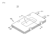
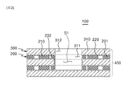
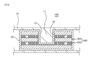
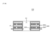
図1および図2に示されたように、本発明の実施例に係るリチウムイオン二次電池100は、複数個のポケット式の正極体200と負極体300が交互に積層された電極組立体400を含むことができる。
1 and 2, the lithium ion
前記電極組立体400には、電子機器の電池収納空間に向かって突出した突出部11(図7参照)が挿入されて収容され得る空間部S1が形成されるが、前記空間部S1は、複数個のポケット式の正極体200および負極体300にそれぞれ形成された第1貫通孔212および第2貫通孔312により形成され得る。
The
そして、前記空間部S1は、図2に示されたように、前記電極組立体400に溝の形状に形成され得、図10に示されたように、孔の形状に形成されてもよい。
The space S1 may be formed in the shape of a groove in the
即ち、前記空間部S1が前記電極組立体400に溝の形状に形成される時は、図2に示されたように、前記電極組立体400の最下端に配置された負極体300を除く残りの複数個のポケット式の正極体200および負極体300にそれぞれ形成された第1貫通孔212および第2貫通孔312により形成され得る。
That is, when the space S1 is formed in the shape of a groove in the
これに対し、前記空間部S1が前記電極組立体400に孔の形状に形成される時は、図10に示されたように、前記電極組立体400を構成する複数個のポケット式の正極体200および負極体300のいずれにもそれぞれ形成される第1貫通孔212および第2貫通孔312により形成され得る。
On the other hand, when the space S1 is formed in the shape of a hole in the
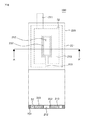
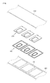
これによって、前記ポケット式の正極体200は、図3および図4に示されたように、正極活物質であるリチウムまたはリチウム金属複合酸化物のコーティング層および無垢突出部211を有し、電子機器の電池収納空間に向かって突出した突出部11が挿入され得る第1貫通孔212が形成された正極板210と、前記無垢突出部211だけを露出させながら前記正極板210の両面を被覆する一対の分離膜220、および前記正極板210の周囲全体または周囲の一部におて前記一対の分離膜220の間に位置し、前記一対の分離膜220に接着されるフィルム部230を含むことができる。
Accordingly, as shown in FIGS. 3 and 4, the pocket-type
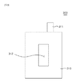
そして、前記負極体300は、図5に示されたように、リチウムを吸蔵、放出できる炭素質負極活物質および無垢突出部311を有し、前記正極板210に形成された第1貫通孔212と対応して連通される第2貫通孔312が形成された負極板310を含むことができる。
As shown in FIG. 5, the
前記負極体300の負極板310は、前記ポケット式の正極体200の正極板210から放出するリチウムイオンを安定的に吸蔵させるために、前記正極板210の大きさより大きく形成されることが必須である。
The
そして、前記空間部S1が溝の形状に形成される時は、前述したように、前記電極組立体400の最下端に配置される負極体300の負極板310に第2貫通孔312が形成されない。これに対し、前記空間部S1が前記電極組立体400を貫通する孔の形状に形成される時は、前記電極組立体400を構成する負極体300の負極板310のいずれにも第2貫通孔312が形成され得る。
When the space S1 is formed in the shape of a groove, as described above, the second through
前記空間部S1の形状は、電子機器の電池収納空間に向かって突出した突出部11(図7参照)の突出長さ、突出方向および個数などに対応して溝または孔の形状に形成され得、これによって、前記第2貫通孔312が前記電極組立体400の最下端に配置される負極体300の負極板310に選択的に形成されても、形成されなくてもよい。
The shape of the space S1 may be formed in the shape of a groove or a hole corresponding to the protruding length, protruding direction, number, and the like of the protruding portions 11 (see FIG. 7) protruding toward the battery storage space of the electronic device. Accordingly, the second through
そして、前記ポケット式の正極体200のフィルム部230は、図3および図4に示されたように、前記正極板210の外周の全体または外周の一部に沿って前記一対の分離膜220の間に位置し、前記一対の分離膜220に接着される第1絶縁性部材231と、前記第1貫通孔212を区画して形成する前記正極板210の内周の全体または内周の一部に沿って前記一対の分離膜220の間に位置し、前記一対の分離膜220に接着される第2絶縁性部材232を含むことができる。
As shown in FIGS. 3 and 4, the
前記第1絶縁性部材231と前記第2絶縁性部材232は、互いに協力して前記正極板210が収容され得る打抜空間S2を形成することができる。
The first insulating
前記打抜空間S2は、前記正極板210が収容され得る形状または大きさを有し、本発明の実施例においては、前記正極板210の形状と対応する四角枠の形状に形成されたが、これに限定されず、円形および多角形状の枠形状に作製されてもよい。
The punching space S2 has a shape or size that can accommodate the
そして、前記正極板210は、前記打抜空間S2を形成する前記第1絶縁性部材231および前記第2絶縁性部材232と離隔されて一定間隔を有したまま前記打抜空間S2に収容され得る。
The
即ち、前記正極板210の外側面は、前記第1絶縁性部材231の内側面と離隔され、また、前記第1貫通孔212を形成する前記正極板210の内側面は、前記第2絶縁性部材232の外側面と離隔される。
That is, the outer surface of the
一方、前記フィルム部230は、前記第1絶縁性部材231と前記第2絶縁性部材232を互いに連結する連結部材233をさらに含むことができる。
Meanwhile, the
前記連結部材233は、前記第1絶縁性部材231の内周部分の少なくとも一部と、前記第2絶縁性部材232の外周部分の少なくとも一部とに、両端がそれぞれ連結され得る。
Both ends of the connecting
前記連結部材233は、前記第2絶縁性部材232が前記正極板210の第1貫通孔212に収容され、前記正極板210の内周に沿って配置される過程で、前記第2絶縁性部材232が既設定された位置に置かれ得るようにする。
The
即ち、前記連結部材233は、前記フィルム部230の第1絶縁性部材231が前記一対の分離膜220のうち前記正極板210の下側に配置された分離膜220に置かれれる時に、前記第2絶縁性部材232が前記正極板210の第1貫通孔212に収容され得る位置に配置され得るようにする。
That is, when the first insulating
ここで、前記正極板210には、前記フィルム部230の連結部材233が収容され得る切開部213が形成されることが好ましい。
Here, the
前記切開部213は、前記正極板210が、前記フィルム部230が接着された前記一対の分離膜220のいずれか一つの分離膜220に置かれ、前記フィルム部230が形成する打抜空間S2に収容される時に、前記正極板210が前記フィルム部230の連結部材233の上側に積層された状態で前記打抜空間S2に収容されることを防止する。
In the
仮に、前記正極板210に前記切開部213が形成されなければ、前記正極板210が前記連結部材233の上側に積層された状態となるため、前記正極板210と前記一対の分離膜220との間に間隙が形成され、結局、複数個のポケット式の正極体200と負極体300が交互に積層される時に、前記ポケット式の正極体200と負極体300との間に間隙が形成され、電池の性能が低下し得る。
If the
また、前記連結部材233は、前記第1絶縁性部材231の内周側面の中央と前記第2絶縁性部材232の外周側面の中央を連結するものと図面上に示されたが、それに限定されない。即ち、前記連結部材233が形成される位置または個数は、前記第1絶縁性部材231の内周側面と前記第2絶縁性部材232の外周側面とを互いに連結することができれば、前記第1絶縁性部材231の内周側面と前記第2絶縁性部材232の外周側面の少なくとも一部に選択されて形成され得る。
Further, although the connecting
そして、前記フィルム部230の第1絶縁性部材231と前記第2絶縁性部材232および前記連結部材233には、接着物質が塗布され得る。即ち、前記一対の分離膜220と向かい合う前記第1絶縁性部材231と前記第2絶縁性部材232および前記連結部材233の両面には、それぞれ接着物質が塗布され得る。
An adhesive material may be applied to the first insulating
また、前記フィルム部230の第1絶縁性部材231と前記第2絶縁性部材232および前記連結部材233は、ポリオレフィン樹脂フィルム、ポリエステル樹脂フィルム、ポリスチレン樹脂フィルム、ポリイミドフィルム、ポリアミドフィルム、フルオロカーボン樹脂フィルム、ABSフィルム、ポリアクリル系フィルム、アセタール系フィルム、ポリカーボネートフィルムで構成された群から選択されたいずれか一つを含むことができる。
In addition, the first insulating
そして、前記第1絶縁性部材231と前記第2絶縁性部材232および前記連結部材233は、エチレンビニルアセテート、エチレンエチルアセテート、エチレンアクリリックアシッド系化合物、アイオノマー系化合物、ポリエチレン、ポリビニルアセテート、ポリビニルブチラールで構成された高温溶融型接着物質群から選択されたいずれか一つの接着成分を含むことが好ましい。
The first insulating
また、前記第1絶縁性部材231には、前記正極板210の無垢突出部211が収容され得る収容部231aが形成され得る。
In addition, the first insulating
前記収容部231aは、前記正極板210が前記フィルム部230の打抜空間S2に収容される時に、前記正極板210の無垢突出部211が前記一対の分離膜220のいずれか一つの分離膜220に接着された前記第1絶縁性部材231の上側に積層されることを防止する。
When the
仮に、前記第1絶縁性部材231に前記収容部231aが形成されなければ、前記正極板210の無垢突出部211が前記第1絶縁性部材231の上側に積層された状態となるため、前記正極板210と前記一対の分離膜220との間には、間隙が形成されざるを得ない。これによって、複数個のポケット式の正極体200と負極体300が交互に積層される時に、前記ポケット式の正極体200と負極体300との間に間隙が形成され、電池の性能が低下し得る。
If the
前記収容部231aは、前記第1絶縁性部材231の周方向の一部に形成され得、前記正極板210が前記打抜空間S2に収容される時に、前記正極板210の無垢突出部211と対応する位置に形成され得る。
The
そして、前記一対の分離膜220のいずれか一つの分離膜220には、図6に示されたように、前記フィルム部230の第1絶縁性部材231が置かれる位置を案内する位置決め部221が表示され得る。
In addition, as shown in FIG. 6, a
前記位置決め部221は、作業者が帯状の分離膜220に対して複数個のフィルム部230を既設定された位置に接着させる作業を簡便かつ正確に遂行できるようにする。
The
そして、前記一対の分離膜220の中で前記正極板210の第1貫通孔212と対応する部位は、図示しない加熱加圧手段により加圧され、図2に示されたように、前記第2絶縁性部材232の内周側面と接着され、また、電極組立体400の最下端に配置される負極体300の負極板310の表面と接着される。従って、前記電極組立体400に形成された空間部S1は、前記第1貫通孔212に収容された前記第2絶縁性部材232の内周側面と、前記第2貫通孔312を形成する負極板312の内側面、および前記電極組立体400の最下端に配置される負極板310の上面により溝の形態に形成され得、または、前記第1貫通孔212に収容された前記第2絶縁性部材232の内周側面と、前記第2貫通孔212を形成する負極板312の内側面により孔の形態に形成され得る。
Then, portions of the pair of
これによって、図7に示されたように、電子機器の電池収納空間に向かって突出した電子機器10の突出部11が前記電極組立体400を取り囲む電池缶20の溝21に収容された状態で前記空間部S1に挿入され得る。
Accordingly, as shown in FIG. 7, the protruding
一方、前記のように構成された、本発明の実施例に係るリチウムイオン二次電池100は、様々なパッケージング(packing)素材により密封され得、どのようなパッケージング素材を使用するかによって缶タイプまたはパウチタイプの電池に用いられ得る。
Meanwhile, the lithium ion
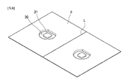
このとき、前記リチウムイオン二次電池100を密封するパッケージング素材が軟性材のパウチである場合は、図8に示されたように、前記パウチPに電極組立体400が収納され得る一対の収容溝30と、前記一対の収容溝31内で突出し、前記電極組立体400に形成された空間部S1に挿入される挿入部31を形成させることが好ましい。
At this time, when the packaging material for sealing the lithium ion
前記一対の収容溝30は、前記電極組立体400の外形と対応する形状に形成され、前記パウチPが折れ目Lを基準に半分に折れるとき、互いに対応する位置に形成されることが好ましい。
The pair of receiving
なぜなら、前記一対の収容溝30の中でいずれか一つの収容溝30に挿入された電極組立体400の密封作業を実施する時に、作業者が前記パウチPを折れ目Lに沿って半分に折るだけで、前記一対の収容溝30が互いに型合わせされ、前記電極組立体400を密封できるからである。
This is because when the
そして、前記挿入部31は、前記一対の収容溝30それぞれに形成され得、または、前記一対の収容溝30のいずれか一つの収容溝30にのみ形成され得る。即ち、前記挿入部31は、前記電極組立体400に形成された空間部S1が溝の形状に形成された時は、前記一対の収容溝30のいずれか一つの収容溝30にのみ形成され、逆に、前記空間部S1が孔の形状に形成された時は、図8に示されたように、前記一対の収容溝30それぞれに形成され、前記電極組立体400の空間部S1の上部および下部にそれぞれ挿入され得る。
The
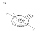
前記のような構成を有するパウチPは、図9および図10に示されたように、前記電極組立体400を密封した状態で前記電極組立体400の外形に対応する形状にカッティングされた後、そのカッティング部位がシーリング(sealing)され得る。このとき、前記電極組立体400の空間部S1に挿入された前記パウチPの挿入部31の中で前記空間部S1を区画形成する前記電極組立体400の内側面と接合しない部位もカッティングされた後、そのカッティング部位がシーリングされ得る。
The pouch P having the above-described configuration is cut into a shape corresponding to the outer shape of the
参考までに、図10には、前記電極組立体400に形成された空間部S1が前記電極組立体400を貫通する孔の形状を有するものと示されている。
For reference, FIG. 10 shows that the space S <b> 1 formed in the
前記のような構成を有する本発明の実施例に係るリチウムイオン二次電池100は、電子機器の二次電池収納空間の残余空間を最大限活用することができるので、電池容量および電池使用時間を増やすことができる。
Since the lithium ion
また、本発明の実施例に係るリチウムイオン二次電池100は、電子機器の二次電池収納空間を既存の角形や円筒形に限定しないため、電子機器を様々なデザインで設計可能にすることができる。
In addition, the lithium ion
これまで本発明に係る具体的な一実施例について説明したが、本発明の範囲から外れない限度内では種々の変形が可能であることはもちろんである。 Although a specific embodiment according to the present invention has been described so far, it goes without saying that various modifications can be made without departing from the scope of the present invention.
それゆえ、本発明の範囲は、説明された実施例に限定されて定められてはならず、後述する特許請求の範囲だけではなく、この特許請求の範囲と均等なものにより定められるべきである。 Therefore, the scope of the present invention should not be defined by being limited to the embodiments described, but should be defined not only by the claims described below, but by equivalents thereof. .
本発明は、スマートフォン、カメラ、ノートパソコンなどの様々な電子機器に適用され得、電子機器と共に消費者に販売または別途販売され得る。 The present invention can be applied to various electronic devices such as a smartphone, a camera, and a laptop computer, and can be sold to consumers or sold separately together with the electronic devices.
Claims (16)
前記電極組立体には、陰刻で陥没した空間部が形成され、
前記空間部には、電子機器の突出部が挿入されることを特徴とする、リチウムイオン二次電池。 In a secondary battery including an electrode assembly in which a plurality of pocket-type positive electrode bodies and negative electrode bodies are alternately stacked,
The electrode assembly is formed with a space depressed by indentation,
A protrusion of an electronic device is inserted into the space portion, the lithium ion secondary battery.
正極活物質であるリチウムまたはリチウム金属複合酸化物のコーティング層および無垢突出部を有し、第1貫通孔が形成された正極板;
前記無垢突出部だけを露出させながら前記正極板の両面を被覆する一対の分離膜;および
前記正極板の外周の全体または外周の一部に沿って、前記一対の分離膜の間に位置し、前記一対の分離膜に接着されるフィルム部;を含むことを特徴とする、請求項1に記載のリチウムイオン二次電池。 The pocket type positive electrode body is:
A positive electrode plate having a coating layer of lithium or lithium metal composite oxide as a positive electrode active material and a solid protrusion, and having a first through hole;
A pair of separation membranes covering both surfaces of the positive electrode plate while exposing only the solid protrusion; and along the whole or a part of the outer periphery of the positive electrode plate, located between the pair of separation membranes, The lithium ion secondary battery according to claim 1, further comprising: a film portion bonded to the pair of separation membranes.
前記正極板の外周の全体または外周の一部に沿って、前記一対の分離膜の間に位置し、前記一対の分離膜に接着される第1絶縁性部材;および
前記第1貫通孔を形成する前記正極板の内周の全体または内周の一部に沿って、前記一対の分離膜の間に位置し、前記一対の分離膜に接着される第2絶縁性部材;を含むことを特徴とする、請求項2に記載のリチウムイオン二次電池。 The film part is
A first insulating member that is positioned between the pair of separation films and adhered to the pair of separation films along the entire outer periphery or a part of the outer periphery of the positive electrode plate; and the first through hole is formed A second insulating member that is positioned between the pair of separation films along the entire inner periphery or a part of the inner periphery of the positive electrode plate and is bonded to the pair of separation films. The lithium ion secondary battery according to claim 2.
前記第1絶縁性部材と前記第2絶縁性部材とを互いに連結する連結部材を含むことを特徴とする、請求項3に記載のリチウムイオン二次電池。 The film part is
The lithium ion secondary battery according to claim 3, further comprising a connecting member that connects the first insulating member and the second insulating member to each other.
リチウムを吸蔵、放出できる炭素質負極活物質コーティング層および無垢突出部を有する負極板を含み、
前記負極体の負極板には、前記第1貫通孔と対応して連通される第2貫通孔が形成されることを特徴とする、請求項1に記載のリチウムイオン二次電池。 The negative electrode body is
Including a negative electrode plate having a carbonaceous negative electrode active material coating layer capable of inserting and extracting lithium and a solid protrusion,
2. The lithium ion secondary battery according to claim 1, wherein a second through hole communicating with the first through hole is formed in the negative electrode plate of the negative electrode body. 3.
前記第1貫通孔に収容された前記第2絶縁性部材の内側面と、前記第2貫通孔を形成する負極板の内側面により孔の形状に形成されるか、前記第1貫通孔に収容された前記第2絶縁性部材の内側面と、前記第2貫通孔を形成する負極板の内側面、および前記電極組立体の最下端に配置される負極板の上面により溝の形状に形成されることを特徴とする、請求項9に記載のリチウムイオン二次電池。 The space formed in the electrode assembly is:
The inner surface of the second insulating member accommodated in the first through hole and the inner surface of the negative electrode plate forming the second through hole are formed in a hole shape or accommodated in the first through hole. The inner surface of the second insulating member thus formed, the inner surface of the negative electrode plate forming the second through-hole, and the upper surface of the negative electrode plate disposed at the lowermost end of the electrode assembly are formed into a groove shape. The lithium ion secondary battery according to claim 9, wherein:
Applications Claiming Priority (3)
| Application Number | Priority Date | Filing Date | Title |
|---|---|---|---|
| KR10-2015-0086922 | 2015-06-18 | ||
| KR1020150086922A KR101681758B1 (en) | 2015-06-18 | 2015-06-18 | Lithium ion secondary battery |
| PCT/KR2016/006251 WO2016204467A1 (en) | 2015-06-18 | 2016-06-13 | Lithium ion secondary battery |
Publications (2)
| Publication Number | Publication Date |
|---|---|
| JP2018519636A true JP2018519636A (en) | 2018-07-19 |
| JP6643736B2 JP6643736B2 (en) | 2020-02-12 |
Family
ID=57546030
Family Applications (1)
| Application Number | Title | Priority Date | Filing Date |
|---|---|---|---|
| JP2017565947A Active JP6643736B2 (en) | 2015-06-18 | 2016-06-13 | Lithium ion secondary battery |
Country Status (6)
| Country | Link |
|---|---|
| US (1) | US10559790B2 (en) |
| EP (1) | EP3312928B1 (en) |
| JP (1) | JP6643736B2 (en) |
| KR (1) | KR101681758B1 (en) |
| CN (1) | CN107750407B (en) |
| WO (1) | WO2016204467A1 (en) |
Cited By (1)
| Publication number | Priority date | Publication date | Assignee | Title |
|---|---|---|---|---|
| WO2021085664A1 (en) * | 2019-10-29 | 2021-05-06 | 주식회사 엘지에너지솔루션 | Secondary battery |
Families Citing this family (3)
| Publication number | Priority date | Publication date | Assignee | Title |
|---|---|---|---|---|
| PL3503257T3 (en) | 2017-03-10 | 2021-08-02 | Lg Chem, Ltd. | Lithium secondary battery |
| EP3591729A1 (en) | 2018-07-03 | 2020-01-08 | Renata AG | A multilayer packaging structure for a thin film battery and a method for manufacturing of such a structure |
| KR102552243B1 (en) * | 2018-09-13 | 2023-07-07 | 주식회사 엘지에너지솔루션 | Secondary battery and electronic device including the same |
Citations (6)
| Publication number | Priority date | Publication date | Assignee | Title |
|---|---|---|---|---|
| JP2012209072A (en) * | 2011-03-29 | 2012-10-25 | Nec Corp | Electrode laminate of electrode laminated battery and manufacturing method of the electrode laminate |
| KR20130105272A (en) * | 2012-03-14 | 2013-09-25 | 주식회사 엘지화학 | Battery cell havig through hole and battery pack comprising the same |
| KR20140034974A (en) * | 2012-09-11 | 2014-03-21 | 주식회사 루트제이드 | Wrapping electrode plate for use in lithium ion secondary battery and manufacturing method of the same |
| US20140113184A1 (en) * | 2012-10-18 | 2014-04-24 | Apple Inc. | Three-dimensional non-rectangular battery cell structures |
| KR20140102379A (en) * | 2013-02-13 | 2014-08-22 | 주식회사 엘지화학 | Battery Cell of Irregular Structure |
| US20150033547A1 (en) * | 2013-06-28 | 2015-02-05 | Lg Chem, Ltd. | Electrode assembly manufacturing method including separator cutting process |
Family Cites Families (5)
| Publication number | Priority date | Publication date | Assignee | Title |
|---|---|---|---|---|
| KR100337707B1 (en) | 2000-09-25 | 2002-05-22 | 정근창 | Pocketed electrode plate for use in lithium ion secondary battery, its manufacturing method and lithium ion secondary battery using the same |
| KR101168651B1 (en) | 2010-06-21 | 2012-07-26 | 주식회사 루트제이드 | Pocketed electrode plate, electrode assembly and lithium secondary battery using thereof |
| KR101168650B1 (en) | 2010-06-21 | 2012-07-25 | 주식회사 루트제이드 | Pocketed electrode plate, electrode assembly and lithium secondary battery using thereof |
| KR101387617B1 (en) * | 2012-09-11 | 2014-04-24 | 주식회사 루트제이드 | Separator for electrode assembly of secondary battery and secondary battery having the same |
| KR101619604B1 (en) * | 2013-09-26 | 2016-05-10 | 주식회사 엘지화학 | Method of manufacturing electrode assembly and secondary battery |
-
2015
- 2015-06-18 KR KR1020150086922A patent/KR101681758B1/en active Active
-
2016
- 2016-06-13 US US15/736,692 patent/US10559790B2/en active Active
- 2016-06-13 EP EP16811880.0A patent/EP3312928B1/en active Active
- 2016-06-13 WO PCT/KR2016/006251 patent/WO2016204467A1/en not_active Ceased
- 2016-06-13 JP JP2017565947A patent/JP6643736B2/en active Active
- 2016-06-13 CN CN201680035516.7A patent/CN107750407B/en active Active
Patent Citations (7)
| Publication number | Priority date | Publication date | Assignee | Title |
|---|---|---|---|---|
| JP2012209072A (en) * | 2011-03-29 | 2012-10-25 | Nec Corp | Electrode laminate of electrode laminated battery and manufacturing method of the electrode laminate |
| KR20130105272A (en) * | 2012-03-14 | 2013-09-25 | 주식회사 엘지화학 | Battery cell havig through hole and battery pack comprising the same |
| US20150044536A1 (en) * | 2012-03-14 | 2015-02-12 | Lg Chem, Ltd. | Compact battery cell having improved durability and battery pack comprising the same |
| KR20140034974A (en) * | 2012-09-11 | 2014-03-21 | 주식회사 루트제이드 | Wrapping electrode plate for use in lithium ion secondary battery and manufacturing method of the same |
| US20140113184A1 (en) * | 2012-10-18 | 2014-04-24 | Apple Inc. | Three-dimensional non-rectangular battery cell structures |
| KR20140102379A (en) * | 2013-02-13 | 2014-08-22 | 주식회사 엘지화학 | Battery Cell of Irregular Structure |
| US20150033547A1 (en) * | 2013-06-28 | 2015-02-05 | Lg Chem, Ltd. | Electrode assembly manufacturing method including separator cutting process |
Cited By (2)
| Publication number | Priority date | Publication date | Assignee | Title |
|---|---|---|---|---|
| WO2021085664A1 (en) * | 2019-10-29 | 2021-05-06 | 주식회사 엘지에너지솔루션 | Secondary battery |
| US12068505B2 (en) | 2019-10-29 | 2024-08-20 | Lg Energy Solution, Ltd. | Secondary battery |
Also Published As
| Publication number | Publication date |
|---|---|
| EP3312928A4 (en) | 2019-03-20 |
| KR101681758B1 (en) | 2016-12-02 |
| US20180183106A1 (en) | 2018-06-28 |
| CN107750407B (en) | 2020-04-17 |
| EP3312928A1 (en) | 2018-04-25 |
| CN107750407A (en) | 2018-03-02 |
| US10559790B2 (en) | 2020-02-11 |
| EP3312928B1 (en) | 2020-04-01 |
| JP6643736B2 (en) | 2020-02-12 |
| WO2016204467A1 (en) | 2016-12-22 |
Similar Documents
| Publication | Publication Date | Title |
|---|---|---|
| KR101406038B1 (en) | Wrapping electrode plate for use in lithium ion secondary battery and manufacturing method of the same | |
| EP4109617A2 (en) | Electrochemical apparatus and electronic apparatus | |
| KR101168651B1 (en) | Pocketed electrode plate, electrode assembly and lithium secondary battery using thereof | |
| TWI518970B (en) | Electrode assembly having step portion in stabilized stacking and method of manufacturing the same | |
| US9325032B2 (en) | Electrode assembly, battery and device including the same | |
| KR102483158B1 (en) | The Method For Manufacturing Secondary Battery And The Apparatus For Degassing Secondary Battery | |
| KR101628892B1 (en) | Secondary battery having stepped cell structure | |
| JP2011129497A (en) | Secondary battery | |
| KR101428541B1 (en) | Wrapping electrode plate for use in lithium ion secondary battery and manufacturing method of the same | |
| JP2018519636A (en) | Lithium ion secondary battery | |
| JP2010033922A (en) | Layered secondary battery | |
| KR20120075953A (en) | Electrode assembly and manufacture thereof | |
| KR102234286B1 (en) | Curved secondary battery | |
| JP2021518039A (en) | Cylindrical secondary battery | |
| CN106797045B (en) | A battery including a battery case with raised protrusions corresponding to a stepped electrode assembly | |
| KR101616426B1 (en) | Secondary battery having stepped cell structure | |
| KR102274052B1 (en) | Method of manufacturing pocketed electrode plate | |
| KR101834605B1 (en) | Polymer Battery And Manufacturing Method | |
| KR101719396B1 (en) | Electrode assembly and method for manufacturing the same | |
| KR101308294B1 (en) | Electrode assembly with means leveling thickness and rechargeable battery in using same | |
| KR102340101B1 (en) | Battery and method for manufcturing the same | |
| KR20220135585A (en) | Pouch type battery include internal frame | |
| KR20220040361A (en) | Rechargeable battery manufacturing method and rechargeable battery |
Legal Events
| Date | Code | Title | Description |
|---|---|---|---|
| A621 | Written request for application examination |
Free format text: JAPANESE INTERMEDIATE CODE: A621 Effective date: 20180320 |
|
| A977 | Report on retrieval |
Free format text: JAPANESE INTERMEDIATE CODE: A971007 Effective date: 20190306 |
|
| A131 | Notification of reasons for refusal |
Free format text: JAPANESE INTERMEDIATE CODE: A131 Effective date: 20190319 |
|
| A521 | Request for written amendment filed |
Free format text: JAPANESE INTERMEDIATE CODE: A523 Effective date: 20190618 |
|
| TRDD | Decision of grant or rejection written | ||
| A01 | Written decision to grant a patent or to grant a registration (utility model) |
Free format text: JAPANESE INTERMEDIATE CODE: A01 Effective date: 20191119 |
|
| A61 | First payment of annual fees (during grant procedure) |
Free format text: JAPANESE INTERMEDIATE CODE: A61 Effective date: 20191216 |
|
| R150 | Certificate of patent or registration of utility model |
Ref document number: 6643736 Country of ref document: JP Free format text: JAPANESE INTERMEDIATE CODE: R150 |
|
| R250 | Receipt of annual fees |
Free format text: JAPANESE INTERMEDIATE CODE: R250 |
|
| R250 | Receipt of annual fees |
Free format text: JAPANESE INTERMEDIATE CODE: R250 |
|
| R250 | Receipt of annual fees |
Free format text: JAPANESE INTERMEDIATE CODE: R250 |
|
| R250 | Receipt of annual fees |
Free format text: JAPANESE INTERMEDIATE CODE: R250 |