JP2018519640A - Illumination device for automatic vehicle floodlight - Google Patents
Illumination device for automatic vehicle floodlight Download PDFInfo
- Publication number
- JP2018519640A JP2018519640A JP2017568036A JP2017568036A JP2018519640A JP 2018519640 A JP2018519640 A JP 2018519640A JP 2017568036 A JP2017568036 A JP 2017568036A JP 2017568036 A JP2017568036 A JP 2017568036A JP 2018519640 A JP2018519640 A JP 2018519640A
- Authority
- JP
- Japan
- Prior art keywords
- lighting device
- optical structure
- light emitting
- emitting module
- light
- Prior art date
- Legal status (The legal status is an assumption and is not a legal conclusion. Google has not performed a legal analysis and makes no representation as to the accuracy of the status listed.)
- Granted
Links
Images

Classifications
-
- F—MECHANICAL ENGINEERING; LIGHTING; HEATING; WEAPONS; BLASTING
- F21—LIGHTING
- F21S—NON-PORTABLE LIGHTING DEVICES; SYSTEMS THEREOF; VEHICLE LIGHTING DEVICES SPECIALLY ADAPTED FOR VEHICLE EXTERIORS
- F21S41/00—Illuminating devices specially adapted for vehicle exteriors, e.g. headlamps
- F21S41/60—Illuminating devices specially adapted for vehicle exteriors, e.g. headlamps characterised by a variable light distribution
- F21S41/67—Illuminating devices specially adapted for vehicle exteriors, e.g. headlamps characterised by a variable light distribution by acting on reflectors
- F21S41/675—Illuminating devices specially adapted for vehicle exteriors, e.g. headlamps characterised by a variable light distribution by acting on reflectors by moving reflectors
-
- F—MECHANICAL ENGINEERING; LIGHTING; HEATING; WEAPONS; BLASTING
- F21—LIGHTING
- F21S—NON-PORTABLE LIGHTING DEVICES; SYSTEMS THEREOF; VEHICLE LIGHTING DEVICES SPECIALLY ADAPTED FOR VEHICLE EXTERIORS
- F21S41/00—Illuminating devices specially adapted for vehicle exteriors, e.g. headlamps
- F21S41/10—Illuminating devices specially adapted for vehicle exteriors, e.g. headlamps characterised by the light source
- F21S41/14—Illuminating devices specially adapted for vehicle exteriors, e.g. headlamps characterised by the light source characterised by the type of light source
-
- F—MECHANICAL ENGINEERING; LIGHTING; HEATING; WEAPONS; BLASTING
- F21—LIGHTING
- F21S—NON-PORTABLE LIGHTING DEVICES; SYSTEMS THEREOF; VEHICLE LIGHTING DEVICES SPECIALLY ADAPTED FOR VEHICLE EXTERIORS
- F21S41/00—Illuminating devices specially adapted for vehicle exteriors, e.g. headlamps
- F21S41/10—Illuminating devices specially adapted for vehicle exteriors, e.g. headlamps characterised by the light source
- F21S41/14—Illuminating devices specially adapted for vehicle exteriors, e.g. headlamps characterised by the light source characterised by the type of light source
- F21S41/16—Laser light sources
-
- F—MECHANICAL ENGINEERING; LIGHTING; HEATING; WEAPONS; BLASTING
- F21—LIGHTING
- F21S—NON-PORTABLE LIGHTING DEVICES; SYSTEMS THEREOF; VEHICLE LIGHTING DEVICES SPECIALLY ADAPTED FOR VEHICLE EXTERIORS
- F21S41/00—Illuminating devices specially adapted for vehicle exteriors, e.g. headlamps
- F21S41/10—Illuminating devices specially adapted for vehicle exteriors, e.g. headlamps characterised by the light source
- F21S41/14—Illuminating devices specially adapted for vehicle exteriors, e.g. headlamps characterised by the light source characterised by the type of light source
- F21S41/176—Light sources where the light is generated by photoluminescent material spaced from a primary light generating element
-
- F—MECHANICAL ENGINEERING; LIGHTING; HEATING; WEAPONS; BLASTING
- F21—LIGHTING
- F21S—NON-PORTABLE LIGHTING DEVICES; SYSTEMS THEREOF; VEHICLE LIGHTING DEVICES SPECIALLY ADAPTED FOR VEHICLE EXTERIORS
- F21S41/00—Illuminating devices specially adapted for vehicle exteriors, e.g. headlamps
- F21S41/10—Illuminating devices specially adapted for vehicle exteriors, e.g. headlamps characterised by the light source
- F21S41/19—Attachment of light sources or lamp holders
- F21S41/192—Details of lamp holders, terminals or connectors
-
- F—MECHANICAL ENGINEERING; LIGHTING; HEATING; WEAPONS; BLASTING
- F21—LIGHTING
- F21S—NON-PORTABLE LIGHTING DEVICES; SYSTEMS THEREOF; VEHICLE LIGHTING DEVICES SPECIALLY ADAPTED FOR VEHICLE EXTERIORS
- F21S41/00—Illuminating devices specially adapted for vehicle exteriors, e.g. headlamps
- F21S41/30—Illuminating devices specially adapted for vehicle exteriors, e.g. headlamps characterised by reflectors
- F21S41/32—Optical layout thereof
-
- F—MECHANICAL ENGINEERING; LIGHTING; HEATING; WEAPONS; BLASTING
- F21—LIGHTING
- F21S—NON-PORTABLE LIGHTING DEVICES; SYSTEMS THEREOF; VEHICLE LIGHTING DEVICES SPECIALLY ADAPTED FOR VEHICLE EXTERIORS
- F21S41/00—Illuminating devices specially adapted for vehicle exteriors, e.g. headlamps
- F21S41/30—Illuminating devices specially adapted for vehicle exteriors, e.g. headlamps characterised by reflectors
- F21S41/39—Attachment thereof
-
- F—MECHANICAL ENGINEERING; LIGHTING; HEATING; WEAPONS; BLASTING
- F21—LIGHTING
- F21S—NON-PORTABLE LIGHTING DEVICES; SYSTEMS THEREOF; VEHICLE LIGHTING DEVICES SPECIALLY ADAPTED FOR VEHICLE EXTERIORS
- F21S45/00—Arrangements within vehicle lighting devices specially adapted for vehicle exteriors, for purposes other than emission or distribution of light
- F21S45/40—Cooling of lighting devices
- F21S45/47—Passive cooling, e.g. using fins, thermal conductive elements or openings
-
- F—MECHANICAL ENGINEERING; LIGHTING; HEATING; WEAPONS; BLASTING
- F21—LIGHTING
- F21V—FUNCTIONAL FEATURES OR DETAILS OF LIGHTING DEVICES OR SYSTEMS THEREOF; STRUCTURAL COMBINATIONS OF LIGHTING DEVICES WITH OTHER ARTICLES, NOT OTHERWISE PROVIDED FOR
- F21V7/00—Reflectors for light sources
- F21V7/04—Optical design
- F21V7/07—Optical design with hyperbolic curvature
-
- F—MECHANICAL ENGINEERING; LIGHTING; HEATING; WEAPONS; BLASTING
- F21—LIGHTING
- F21K—NON-ELECTRIC LIGHT SOURCES USING LUMINESCENCE; LIGHT SOURCES USING ELECTROCHEMILUMINESCENCE; LIGHT SOURCES USING CHARGES OF COMBUSTIBLE MATERIAL; LIGHT SOURCES USING SEMICONDUCTOR DEVICES AS LIGHT-GENERATING ELEMENTS; LIGHT SOURCES NOT OTHERWISE PROVIDED FOR
- F21K9/00—Light sources using semiconductor devices as light-generating elements, e.g. using light-emitting diodes [LED] or lasers
- F21K9/60—Optical arrangements integrated in the light source, e.g. for improving the colour rendering index or the light extraction
- F21K9/64—Optical arrangements integrated in the light source, e.g. for improving the colour rendering index or the light extraction using wavelength conversion means distinct or spaced from the light-generating element, e.g. a remote phosphor layer
-
- F—MECHANICAL ENGINEERING; LIGHTING; HEATING; WEAPONS; BLASTING
- F21—LIGHTING
- F21Y—INDEXING SCHEME ASSOCIATED WITH SUBCLASSES F21K, F21L, F21S and F21V, RELATING TO THE FORM OR THE KIND OF THE LIGHT SOURCES OR OF THE COLOUR OF THE LIGHT EMITTED
- F21Y2101/00—Point-like light sources
Landscapes
- Engineering & Computer Science (AREA)
- General Engineering & Computer Science (AREA)
- Physics & Mathematics (AREA)
- Optics & Photonics (AREA)
- Microelectronics & Electronic Packaging (AREA)
- Non-Portable Lighting Devices Or Systems Thereof (AREA)
- Lighting Device Outwards From Vehicle And Optical Signal (AREA)
Abstract
【課題】自動車用投光装置の照明装置の個々のコンポーネントに製造不正確性がある場合であっても、所望の光像を簡単な方法で形成可能にすること。【解決手段】照明装置(1)は、可視光を放射する少なくとも1つの発光モジュール(2)、発光モジュール(2)の光を偏向及び/又は整形する少なくとも1つの光学構造体(3)、及び、発光モジュール(2)と結合され、少なくとも1つの光学構造体(3)を支持する保持モジュール(4)を含み。発光モジュール(2)は少なくとも1つのレーザ光源(2a)及び光変換要素(2b)を含む。少なくとも1つのレーザ光源(2a)の光は光変換要素(2b)に導かれ、光変換要素(2b)はその光を可視光に変換して光学構造体(3)内に放射しする。保持モジュール(4)は少なくとも第1及び第2案内手段(4b’、4h)を有する。光学構造体(3)は、第1案内手段(4b’)によって第1方向(x)に、第2案内手段(4h)によって第2方向(z)に、光変換要素(2b)に対しシフト可能である。第1方向(x)と第2方向(z)は互いに対し異なる方向である。【選択図】図1A desired light image can be formed by a simple method even when individual components of an illumination device of an automotive floodlight have manufacturing inaccuracies. The lighting device (1) comprises at least one light emitting module (2) that emits visible light, at least one optical structure (3) that deflects and / or shapes light of the light emitting module (2), and A holding module (4) coupled to the light emitting module (2) and supporting at least one optical structure (3). The light emitting module (2) includes at least one laser light source (2a) and a light conversion element (2b). The light of at least one laser light source (2a) is guided to the light conversion element (2b), which converts the light into visible light and emits it into the optical structure (3). The holding module (4) has at least first and second guide means (4b ', 4h). The optical structure (3) is shifted relative to the light conversion element (2b) in the first direction (x) by the first guiding means (4b ′) and in the second direction (z) by the second guiding means (4h). Is possible. The first direction (x) and the second direction (z) are different from each other. [Selection] Figure 1
Description
本発明は、自動車両用投光装置の照明装置であって、該照明装置は、可視光を放射する少なくとも1つの発光モジュール、発光モジュールの光を偏向及び/又は整形する少なくとも1つの光学構造体、及び、発光モジュールと結合され、少なくとも1つの光学構造体を支持する保持モジュールを含み、発光モジュールは少なくとも1つのレーザ光源及び光変換要素を含み、少なくとも1つのレーザ光源の光は光変換要素に導かれ、光変換要素はその光を可視光に変換して光学構造体内に放射する、照明装置に関する。 The present invention relates to a lighting device for a vehicle floodlighting device, the lighting device including at least one light emitting module that emits visible light, at least one optical structure that deflects and / or shapes light from the light emitting module, And a holding module coupled to the light emitting module and supporting at least one optical structure, the light emitting module including at least one laser light source and a light converting element, wherein light of the at least one laser light source is guided to the light converting element. The light conversion element relates to a lighting device that converts the light into visible light and emits it into the optical structure.
本発明は、更に、少なくとも1つの本発明の照明装置を有する自動車両用投光装置に関する。 The invention further relates to a floodlight device for a motor vehicle comprising at least one lighting device according to the invention.
発光モジュールがそれに後置された光学構造体に固定的に結合されている照明装置であって、光学構造体が発光モジュールから放射された光を例えば道路に投射するものは、従来技術から既知になっている。従って、それによって形成される光像は、発光モジュールの光分布にも、光学構造体の光学特性にも依存する。例えば公差の不正確性に起因して発光モジュールや光学構造体の製造の際に生成し得る又は発光モジュールに対する光学構造体の不正確な位置決めによって引き起こされ得るエラーは、所望の光像からのずれをもたらす。 A lighting device in which a light emitting module is fixedly coupled to an optical structure placed behind it, the optical structure projecting light emitted from the light emitting module onto a road, for example, is known from the prior art It has become. Therefore, the optical image formed thereby depends on both the light distribution of the light emitting module and the optical characteristics of the optical structure. Errors that can be generated during the manufacture of light emitting modules or optical structures, for example due to tolerance inaccuracies, or that can be caused by inaccurate positioning of the optical structures relative to the light emitting modules, are offset from the desired optical image. Bring.
それゆえ、本発明の課題は、当該照明装置の個々のコンポーネントが何らかの製造不正確性を含み得る場合であっても、所望の光像を簡単な方法で形成可能な照明装置を提供することである。 Therefore, an object of the present invention is to provide a lighting device that can form a desired light image in a simple manner, even if individual components of the lighting device may contain some manufacturing inaccuracies. is there.
この課題は、冒頭に記載したタイプの照明装置において、本発明に応じ、保持モジュールは少なくとも第1及び第2案内手段を有し、光学構造体は、第1案内手段によって第1方向に、第2案内手段によって第2方向に、光変換要素に対しシフト可能であり、第1方向と第2方向は互いに対し異なる方向である、ことによって解決される。 According to the invention, in the illumination device of the type described at the outset, the holding module has at least first and second guide means, and the optical structure is arranged in the first direction by the first guide means in the first direction. This is solved by the fact that the two guiding means can shift in the second direction relative to the light conversion element, the first direction and the second direction being different from each other.
光を放射する光変換要素に対し光学構造体をシフトすること、かくして、光変換要素の、光変換要素における光分布の中心の及び光学構造体の誤った位置を補償することが、本発明により可能になる。 Shifting the optical structure relative to the light converting element that emits light, thus compensating for the incorrect position of the light converting element, the center of the light distribution in the light converting element and of the optical structure. It becomes possible.
第1方向及び第2方向に沿ったシフトとは、典型的には、直線的(直進的)運動である。少なくとも1つのレーザ光源の光は、光変換要素に直接的に向けられることができ、又は幾つかの光学素子を介して光変換要素に向けられることができる。 The shift along the first direction and the second direction is typically a linear (straight) movement. The light of the at least one laser light source can be directed directly to the light conversion element or can be directed to the light conversion element via several optical elements.
有利には、発光モジュールはレーザ光源及び光変換要素を取り囲むハウジングを含み、保持モジュールは光学構造体を受容するよう構成された担持要素を含み、担持要素は第1案内手段によってハウジングに対しシフト可能であり、第1案内手段はハウジングに直接係合するよう、構成可能である。第1案内手段とは、例えば、担持要素が相応の突出部によって嵌り込む、ハウジングの外側領域に配することが可能なレール状の案内溝である。かくして、格別にコスト的に有利で、コンパクトでかつ簡単な構造が得られる。 Advantageously, the light emitting module comprises a housing surrounding the laser light source and the light converting element, the holding module comprises a carrier element configured to receive the optical structure, the carrier element being shiftable relative to the housing by the first guiding means And the first guide means can be configured to engage directly with the housing. The first guide means is, for example, a rail-shaped guide groove that can be arranged in the outer region of the housing, into which the carrying element is fitted by a corresponding protrusion. In this way, a compact and simple structure is obtained which is particularly advantageous in terms of cost.
これの代わりに、発光モジュールはレーザ光源及び光変換要素を取り囲むハウジングを含み、保持モジュールは担持要素及びアダプタ要素を含み、担持要素は光学構造体を受容するよう構成され、アダプタ要素はハウジングに固定的に結合可能であり、担持要素は第1案内手段によってアダプタ要素に係合しかつアダプタ要素に対しシフト可能であるよう、構成可能である。アダプタ要素を設けることによって、多くの種々異なる発光モジュールを本発明の照明装置のために使用することが可能になるが、これは、アダプタ要素は簡単な方法でそのような発光モジュールの夫々と固定的に結合することができるからである。 Alternatively, the light emitting module includes a housing surrounding the laser light source and the light converting element, the holding module includes a carrier element and an adapter element, the carrier element is configured to receive the optical structure, and the adapter element is secured to the housing. And the carrier element can be configured to engage and shift relative to the adapter element by the first guiding means. Providing an adapter element allows many different light emitting modules to be used for the lighting device of the present invention, since the adapter element is secured to each such light emitting module in a simple manner. It is because it can combine.
ハウジング又はアダプタ(要素)に対するシフトとは、勿論、光変換要素に対するシフトを暗示している。 A shift relative to the housing or adapter (element) implies, of course, a shift relative to the light conversion element.
格別に簡単な構造の照明装置を達成するために、第2案内手段は担持要素に設けられ、光学構造体は第2案内手段によって担持要素に対しシフト可能であるよう、構成可能である。 In order to achieve an illuminating device with a particularly simple structure, the second guiding means is provided on the carrier element, and the optical structure can be configured to be shiftable relative to the carrier element by the second guiding means.
とりわけ、第1方向と第2方向は互いに対し直角に配向されるよう、構成可能である。これによって格別に効率的な設定が可能になる。この場合、両者の方向への運動は互いに対し線形的に非依存的であり、かくして不所望の相互作用を回避することができる。「互いに対し直角に配向され」という表現は、本開示の枠内においては、(両者の方向の間の)なす角が85°〜95°の範囲にある配置と理解される。 In particular, the first direction and the second direction can be configured to be oriented perpendicular to each other. This enables a particularly efficient setting. In this case, the movement in both directions is linearly independent of each other, thus avoiding unwanted interactions. The expression “oriented at right angles to each other” is understood within the framework of the present disclosure as an arrangement in which the angle (between both directions) is in the range of 85 ° to 95 °.
第1方向及び/又は第2方向におけるシフト位置は夫々調節ネジによって固定可能であると、格別に好都合であり得る。とりわけ、この場合、担持要素は第1調節ネジを受容するための孔を有し、第1調節ネジはアダプタ要素のネジ部及び/又は発光モジュールのハウジングのネジ部に螺合し、担持要素と発光モジュールの間に配置された第1弾性要素は担持要素を第1調節ネジのネジ頭の方向において停止位置に押し付けるよう、構成可能である。これによって、第1方向への光学構造体の格別に強固(ないし堅固:robust)かつ同時に簡単な(位置)調整を達成することができる。発光モジュールにアダプタ要素が配されている場合、弾性要素は、勿論、アダプタ(要素)と担持要素の間にも配設可能である。第1弾性要素の格別に実用的な形態は、第1弾性要素が発光モジュールと担持要素の間に配置され、第1調節ネジの周囲を取り囲む、中空シリンダ状のゴム要素であることによって、達成可能である。 It may be particularly advantageous if the shift position in the first direction and / or the second direction can be fixed by means of an adjusting screw, respectively. In particular, in this case, the carrier element has a hole for receiving a first adjustment screw, the first adjustment screw being screwed into the screw part of the adapter element and / or the screw part of the housing of the light emitting module, The first elastic element arranged between the light emitting modules can be configured to press the carrier element against the stop position in the direction of the screw head of the first adjustment screw. This makes it possible to achieve a particularly strong (or robust) and simultaneously simple (position) adjustment of the optical structure in the first direction. When the adapter element is arranged in the light emitting module, the elastic element can of course be arranged between the adapter (element) and the carrier element. A particularly practical form of the first elastic element is achieved by the fact that the first elastic element is a hollow cylindrical rubber element which is arranged between the light emitting module and the carrier element and surrounds the periphery of the first adjusting screw. Is possible.
第1調節ネジの過誤による完全な螺脱(Herausschrauben)を阻止(予防)するために、アダプタ(要素)及び/又は発光モジュールのハウジングは第1弾性要素の弾性力の方向における担持要素のシフト運動を制限する第1ストッパを有するよう、構成可能である。担持要素の対応する面が第1ストッパに当接するまで調節ネジが螺脱されると、調節ネジの更なる螺脱は担持要素の更なる運動には至らず、かくして、最大の偏位(Auslenkung)が認識可能になる。 In order to prevent (prevent) complete unscrewing (Herausschrauben) due to an error of the first adjusting screw, the adapter (element) and / or the housing of the light emitting module is shifted in the direction of the elastic force of the first elastic element. It can be configured to have a first stopper that restricts. When the adjusting screw is screwed out until the corresponding surface of the carrying element abuts the first stopper, further screwing of the adjusting screw does not lead to further movement of the carrying element, thus the maximum displacement (Auslenkung ) Becomes recognizable.
第1弾性要素の押し潰しないし破壊を阻止するために、発光モジュールと担持要素の間に、第1弾性要素の弾性力の方向の反対側への担持要素のシフト運動を制限する第2ストッパが設けられるよう、構成可能である。 In order to prevent crushing or breaking of the first elastic element, a second stopper is provided between the light emitting module and the carrying element to limit the shift movement of the carrying element in the direction opposite to the direction of the elastic force of the first elastic element. It can be configured to be provided.
第2案内手段は担持要素に設けられており、光学構造体は第2案内手段によって担持要素に対しシフト可能であると、格別に好都合であり得る。更に、第2案内手段は担持要素から突設された少なくとも1つの案内レールを有し、該案内レールには光学構造体がシフト可能に支持されており、案内レールの突出端部には案内レールに固定可能な終端要素が設けられており、該終端要素は案内レールの突出端部の方向への光学構造体の運動を制限するものであり、担持要素には光学構造体を案内レールの突出端部の方向に押し付ける第2弾性要素が係合し、終端要素は光学構造体を第2弾性要素の弾性力に抗してシフト可能にする第2調節ネジを有するよう、構成可能である。これによって、第2方向に光学構造体をシフトするための格別に強固(ないし確実)かつ同時に簡単な構造が得られる。 It may be particularly advantageous if the second guiding means is provided on the carrier element and the optical structure can be shifted relative to the carrier element by the second guiding means. Further, the second guide means has at least one guide rail projecting from the carrying element, and an optical structure is supported on the guide rail in a shiftable manner, and the guide rail has a guide rail at the projecting end. A terminal element which can be fixed to the guide element, the terminal element restricting the movement of the optical structure in the direction of the protruding end of the guide rail, and the carrier element is connected to the optical structure by the protrusion of the guide rail. A second elastic element that presses in the direction of the end engages and the termination element can be configured to have a second adjustment screw that allows the optical structure to shift against the elastic force of the second elastic element. Thereby, an exceptionally strong (or reliable) and simultaneously simple structure for shifting the optical structure in the second direction can be obtained.
光学構造体は第2調節ネジの部分(以下においては「係合部分」と称する。)が当接する調整斜面を有し、調整斜面と該係合部分は第2調節ネジの軸方向のシフトが第2方向又はその反対方向への光学構造体のシフト運動に変換されるよう構成されていると、とりわけ好都合であり得る。係合部分は有利には円錐状に構成されている。この場合、第2調節ネジは終端要素を貫通通過し、終端要素の1つの側面に第2調節ネジのネジ頭が配置されておりかつ該側面に対向する側面に係合部分が配置されており、係合部分は終端要素に指向する係合面(係止面)を有し、有利には該ネジ頭は同様に終端要素に指向する係合面(係止面)を有すると、とりわけ有利であり得る。これらの係合面(係止面)は夫々の運動を制限する。 The optical structure has an adjustment slope with which a portion of the second adjustment screw (hereinafter referred to as an “engagement portion”) abuts, and the adjustment slope and the engagement portion are shifted in the axial direction of the second adjustment screw. It can be particularly advantageous if it is arranged to be converted into a shift movement of the optical structure in the second direction or in the opposite direction. The engagement part is preferably conical. In this case, the second adjustment screw passes through the termination element, the screw head of the second adjustment screw is disposed on one side surface of the termination element, and the engaging portion is disposed on the side surface facing the side surface. The engagement part has an engagement surface (locking surface) directed to the end element, and advantageously the screw head has an engagement surface (locking surface) likewise directed to the end element. It can be. These engagement surfaces (locking surfaces) limit their movement.
利用者又はロボットアームにより操作される調節工具による格別に簡単な調節を可能にするために、第1調節ネジと第2調節ネジは互いに対し実質的に平行に配向されるよう、構成可能である。これによって、両者の調節ネジの調節を共通の方向から行うことができる。 The first adjustment screw and the second adjustment screw can be configured to be oriented substantially parallel to each other to allow exceptionally simple adjustment by an adjustment tool operated by a user or robot arm. . Thereby, adjustment of both adjustment screws can be performed from a common direction.
調節プロセスを容易化するために及び手動(手操作)による適合化のためのスタート値を提案するために、発光モジュールには、第1及び第2方向におけるシフト位置のニュートラル位置を表す複数の基準マーキングが設けられ、複数の基準マーキングは、有利には第2調節ネジに対し平行に配向された少なくとも1つの共通の方向から視認可能であるよう、構成可能である。ニュートラル位置とは、第1及び第2方向に沿った光変換要素に対する光学構造体の位置であって、照明装置全体が製造及び組立不正確性がない場合に、所望の光像が達成されるような位置である。 In order to facilitate the adjustment process and to propose starting values for manual (manual) adaptation, the light emitting module has a plurality of criteria representing the neutral position of the shift position in the first and second directions. A marking is provided and the plurality of reference markings are advantageously configurable so that they are visible from at least one common direction oriented parallel to the second adjustment screw. The neutral position is the position of the optical structure relative to the light conversion element along the first and second directions, and the desired light image is achieved when the entire lighting device is free of manufacturing and assembly inaccuracies. It is such a position.
とりわけ、光学構造体は、レンズ及び/又はリフレクタ、とりわけレンズを有するハイパボリック型リフレクタ(hyperbolisch Reflektor)、を含むことが可能である。 In particular, the optical structure can comprise a lens and / or reflector, in particular a hyperbolisch Reflektor with a lens.
更に、別体の冷却体を発光モジュールに設けることも可能である。 Further, a separate cooling body can be provided in the light emitting module.
更に、本発明は、少なくとも1つの本発明の照明装置を有する自動車両用投光装置(前照灯等)に関する。 Furthermore, this invention relates to the floodlight apparatus (headlight etc.) for motor vehicles which has an at least 1 illuminating device of this invention.
本発明は、以下に、図面に記載された例示的かつ非限定的実施例を用いて詳細に説明されている。 The present invention is described in detail below using exemplary and non-limiting examples illustrated in the drawings.
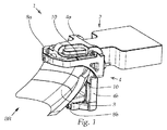
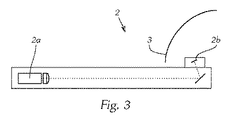
図1は、自動車用投光装置(前照灯等)のための本発明の照明装置1の一例を斜視図で示す。照明装置1は、可視光を放射するための少なくとも1つの発光モジュール2と、発光モジュール2の光を偏向及び/又は整形する光学構造体3を有する。光学構造体3は図示の実施例ではリフレクタとして構成されている。また、光学構造体3は、少なくとも1つのレンズ、(複数の)レンズ及び/又は(複数の)リフレクタの組み合わせ、又は照明目的の光像の形成に適合する原理的に任意のその他の光学コンポーネントからなるレンズシステムであり得る。照明装置1は、更に、発光モジュール2に結合された保持モジュール4を有する。保持モジュール4は、図示の実施例では、2つのコンポーネント即ちアダプタ4a及び担持要素4bを有し、これらは以下に説明する態様で協働する。保持モジュール4は、光学構造体3をシフト可能に受容するよう構成されている。とりわけ図3(これは発光モジュール2の一例の模式図を示す。)において見出すことができるように、発光モジュール2は少なくとも1つのレーザ光源2a及び光変換要素2b(例えば蛍光体(Phosphor))を含み、少なくとも1つのレーザ光源2aの光は光変換要素2bに導かれ、光変換要素2bはレーザ光を可視光に変換して光学構造体3内に放射する。現行の発光モジュール2は、しばしば、夫々のレーザ光が束ねられて1つの光変換要素2bに導かれる複数のレーザ光源2aを含む。
FIG. 1 is a perspective view showing an example of an illuminating device 1 of the present invention for an automotive floodlight (such as a headlamp). The illumination device 1 includes at least one light emitting
保持モジュール4は、後続する(図2以降の)図(複数)に基づき更に詳細に説明されるように、案内手段4b’及び4hを有する。これらの案内手段によって、光学構造体3は、光変換要素2bに対し第1方向x及び第2方向zにシフトされることができる。第1方向xと第2方向zは互いに相違する(互いに異なる方向である)。
The holding
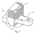
図2は、発光モジュール2の一例を斜視図で示す。この発光モジュール2はその電子的コンポーネントを冷却する冷却体5を付加的に有する。なお、冷却体5は後続する図においては見易さの観点から図示されていない。レーザ光源2aは、光変換要素2bが嵌め込まれているハウジング2cによって取り囲まれている。
FIG. 2 shows an example of the
図4は、発光モジュール2とこれに配されたアダプタ要素4aの一例を斜視図で示す。アダプタ要素4aは、発光モジュール2に外嵌され、例えばネジ4c又はその他の適切な手段によって発光モジュール2に固定される。かくして、アダプタ要素4aは発光モジュール2に固定的に結合される。アダプタ要素4aは、更に、図5及び図6に示された第1弾性要素7aの弾性力の方向において、担持要素4bのシフト運動を制限する第1ストッパ4dを有する。この第1ストッパ4dは、典型的には担持要素4bの組付け後に配されるものであり、図示の実施例ではネジとして構成されている。アダプタ要素4aは、その互いに向かい合う(2つの)側部に夫々1つの凹部(ないし溝部)4a’を有する。凹部4a’は、当該凹部4a’に嵌り込む担持要素4bの嵌合部分4b’を受容及び案内するよう構成されている。第1案内手段は、凹部4a’への嵌合部分4b’の嵌り込みによって構成されている。第1方向xにおける保持モジュール4の案内を可能にする他の任意の構成及び可能性も当業者には勿論既知である。例えば、アダプタ要素4aには、担持要素4bの対応する案内溝に嵌り込む凸部を凹部4b’の代わりに設けることも可能であろう。更に、例えば発光モジュール2が担持要素4bの案内手段4b’に対応するコンポーネントを、とりわけ凸部又は凹部を既に備えている場合、アダプタ要素4aが省略可能でありかつ担持要素4bが直接的に発光モジュール2を掴持する実施形態も考えられる。
FIG. 4 is a perspective view showing an example of the
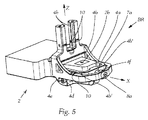
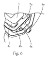
図5は、発光モジュール2と、アダプタ要素4aに取り付けられた担持要素4bの一例を斜視図で示す。担持要素4bは、第1方向xにおいてシフト可能にアダプタ要素4aに支持されており、担持要素4bが外側に(外れる方向に)最大に導かれた(シフトされた)場合に第1ストッパ4dに接触し、以って、第1方向xへの更なるシフトを阻止するよう構成された突出部4c[4e]を有する。担持要素4bは、更に、第1調節ネジ8aを受容する孔4fを有する。調節ネジ8aは、アダプタ要素4aのネジ部及び/又は発光モジュール2のハウジング2cのネジ部に螺入する。アダプタ要素4aと発光モジュール2の間には第1弾性要素7aが配されている。第1弾性要素7aは、担持要素4bを調節ネジ8aのネジ頭の方向における停止位置に押し付けるよう構成されており、発光モジュール2ないしアダプタ要素4aと担持要素4bの間に配置され、第1調節ネジ8aの周囲を取り囲む、中空シリンダ状のゴム要素として構成されている。図6は、これについての詳細例(部分拡大図)を示す。
FIG. 5 is a perspective view showing an example of the
図6では、発光モジュール2ないしアダプタ要素4aと担持要素4bの間に配置されておりかつ第1弾性要素7aの弾性力の方向の反対側への担持要素4bのシフト運動を制限する第2ストッパ4gを見出すことができる。これによって、弾性要素7aの過大な押し付け及びそれに起因する損傷を予防(防止)することができる。両者のストッパ4d及び4gによって、ハウジング2c及びそれに設けられた光変換要素2bに対する担持要素4bのシフトの調節範囲を有効な(合理的な)範囲に制限することができる。
In FIG. 6, the second stopper is arranged between the light emitting
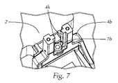
第2方向zにおける光学構造体3のシフトのために、担持要素4bに設けられた第2案内手段4hが設けられている。これについては、以下に、図7〜図9を参照して詳細に説明する。
For the shift of the optical structure 3 in the second direction z, second guide means 4h provided on the
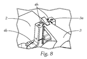
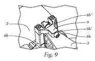
第2案内手段4hは、図示の実施例では、担持要素4bから突設された2つの案内レールから構成されており、該案内レールは光学構造体3を第2方向zにおいてシフト可能に支持するよう構成されている。第2案内手段4hは、それによって第2方向zにおける案内が可能である限りにおいて、異なるように構成されることも勿論可能である。光学構造体3は案内レール4hにシフト可能に支持されている。更に、図9に示されているように、終端要素9が案内レール4hの突出端部に設けられている(ないし案内レール4hの(突出)端部に固定可能である)。終端要素9は案内レールの(突出)端部の方向への光学構造体3の運動を制限する。終端要素9は当該終端要素9を貫通通過する第2調節ネジ8bを有する。終端要素9の1つの側部には、第2調節ネジ8bのネジ頭が配されており、その反対側の側部には、図示の実施例では円錐状に構成されている(第2調節ネジ8bの)係合部分が配されている。係合部分は終端要素9に向けられた係合面(係止面)8b’’を有し、係合面(係止面)8b’’によって、終端要素9に対する第2調節ネジ8bの最大の(位置)変位が制限される。更に、ネジ頭には、終端要素9に指向する更なる係合面(係止面)8b’が設けられるよう、構成可能である。そのような場合、終端要素9は2つの部分から構成可能であり、これら2つの部分の間に第2調節ネジ8bが受容されかつ包囲される。終端要素9を案内レール4hに配置するネジ結合は、当該2つの部分の固定的結合に寄与することができる。
In the illustrated embodiment, the second guide means 4h is composed of two guide rails protruding from the
図8に良好に見出すことができるように、光学構造体3は第2調節ネジ8bの係合部分が当接する調整斜面3aを有し、調整斜面3aと(円錐状)係合部分は第2調節ネジ8bの軸方向のシフトが第2方向z又はその反対方向への光学構造体3のシフト運動に変換されるよう構成されている。
As can be seen well in FIG. 8, the optical structure 3 has an
図7に、担持要素4bに設けられた第2弾性要素7bを見出すことができる。第2弾性要素7bは光学構造体3を案内レール4hの(突出)端部の方向に押し付ける。これによって、調整斜面3aが第2調節ネジ8bの(円錐状)係合部分に向かって押し付けられ、かくして、光学構造体3の定義された停止位置が確定(固定)されることが保証される。第2弾性要素7bは有利な態様で担持要素4bの凹部に着座し(図5において良好に見出すことができる)、かくして、一方では、弾性要素7bの位置は横方向に関し(lateral)固定される。付加的に、弾性要素7bの過大な押し付け及びそれに基づく損傷を阻止することができる。なぜなら、担持要素4bは、光学構造体3のシフト運動を、弾性要素7bの弾性力(の方向)の反対方向において制限するからである。
In FIG. 7, the second
図5、図7、図8及び図9に見出すことができるように、保持モジュール4には、図示の実施例では具体的には担持要素4bには、第1ないし第2方向におけるシフト位置のニュートラル位置を表す複数の基準マーキング10が設けられている。有利には、複数の基準マーキング10は少なくとも1つの共通の注視方向BRから視認可能である。これらの基準マーキング10は例えば刻み目として又は突出部としても構成可能である。
As can be seen in FIGS. 5, 7, 8 and 9, the holding
これについては、例えば、本発明の照明システム1を組立状態で示す図1において良好に見出すことができる。この場合、調節ネジ8a及び8bは互いに対し平行に配向されており、かくして、調節ネジ8a及び8bは、異なる方向からのアプローチを要することなく、簡単な態様で利用者によってアクセスされることができる。 This can be found well, for example, in FIG. 1 showing the lighting system 1 of the invention in an assembled state. In this case, the adjusting screws 8a and 8b are oriented parallel to each other, thus the adjusting screws 8a and 8b can be accessed by the user in a simple manner without requiring approaches from different directions. .
本発明の照明装置1は、光変換要素2bに対する光学構造体3の位置調整を簡単な方法で可能にし、しかも、既述の第1及び第2方向x、zにおけるシフトを可能にする。ここで、第1及び第2方向x、zは相互に異なる方向であり、有利には互いに対し直角に配向されている。本発明の照明装置1を有する自動車用投光装置の場合、2つの方向x及びzは、有利には、自動車用投光装置が自動車に組込まれた状態において方向xが自動車の主走行方向(いわゆる自動車長手軸)に一致し、方向zが垂直(鉛直)軸(いわゆる車高軸)に相当するよう、選択される。
The illuminating device 1 of the present invention makes it possible to adjust the position of the optical structure 3 with respect to the
本発明の教示を考慮することにより、当業者は、本発明の図示されていない他の実施形態に想到することができる。従って、本発明は図示の実施形態には限定されない。重要であるのは、当業者によって本書の知見の下で種々の態様で実施可能であるが、それ自体は不変に留まる本発明の基礎をなす思想である。 In view of the teachings of the present invention, one of ordinary skill in the art will be able to conceive of other non-illustrated embodiments of the present invention. Accordingly, the present invention is not limited to the illustrated embodiment. What is important is a basic idea of the present invention that can be implemented in various ways by those skilled in the art under the knowledge of the present document, but it remains unchanged.
Claims (19)
照明装置(1)は、
・可視光を放射する少なくとも1つの発光モジュール(2)、
・発光モジュール(2)の光を偏向及び/又は整形する少なくとも1つの光学構造体(3)、及び、
・発光モジュール(2)と結合され、少なくとも1つの光学構造体(3)を支持する保持モジュール(4)
を含み、
発光モジュール(2)は少なくとも1つのレーザ光源(2a)及び光変換要素(2b)を含み、
少なくとも1つのレーザ光源(2a)の光は光変換要素(2b)に導かれ、光変換要素(2b)はその光を可視光に変換して光学構造体(3)内に放射し、
保持モジュール(4)は少なくとも第1及び第2案内手段(4b’、4h)を有し、
光学構造体(3)は、第1案内手段(4b’)によって第1方向(x)に、第2案内手段(4h)によって第2方向(z)に、光変換要素(2b)に対しシフト可能であり、
第1方向(x)と第2方向(z)は互いに対し異なる方向である、
照明装置(1)。 A lighting device (1) for a floodlighting device for an automatic vehicle,
The lighting device (1)
At least one light emitting module (2) that emits visible light,
At least one optical structure (3) for deflecting and / or shaping the light of the light emitting module (2), and
A holding module (4) coupled to the light emitting module (2) and supporting at least one optical structure (3)
Including
The light emitting module (2) includes at least one laser light source (2a) and a light conversion element (2b),
The light of the at least one laser light source (2a) is guided to the light conversion element (2b), which converts the light into visible light and emits it into the optical structure (3),
The holding module (4) has at least first and second guiding means (4b ′, 4h),
The optical structure (3) is shifted relative to the light conversion element (2b) in the first direction (x) by the first guiding means (4b ′) and in the second direction (z) by the second guiding means (4h). Is possible,
The first direction (x) and the second direction (z) are different directions with respect to each other,
Lighting device (1).
発光モジュール(2)は、レーザ光源(2a)及び光変換要素(2b)を取り囲むハウジング(2c)を含み、
保持モジュール(4)は、光学構造体(3)を受容するよう構成された担持要素(4b)を含み、
担持要素(4b)は、第1案内手段(4b’)によってハウジング(2c)に対しシフト可能であり、
第1案内手段(4b’)は、ハウジング(2c)に直接係合する、
照明装置(1)。 The lighting device (1) according to claim 1,
The light emitting module (2) includes a housing (2c) surrounding the laser light source (2a) and the light conversion element (2b),
The holding module (4) includes a carrier element (4b) configured to receive the optical structure (3);
The carrier element (4b) can be shifted relative to the housing (2c) by the first guiding means (4b ′),
The first guiding means (4b ′) is directly engaged with the housing (2c).
Lighting device (1).
発光モジュール(2)は、レーザ光源(2a)及び光変換要素(2b)を取り囲むハウジング(2c)を含み、
保持モジュール(4)は、担持要素(4b)及びアダプタ要素(4a)を含み、
担持要素(4b)は、光学構造体(3)を受容するよう構成され、アダプタ要素(4a)は、ハウジング(2c)に固定的に結合可能であり、
担持要素(4b)は、第1案内手段(4b’)によってアダプタ要素(4a、4a’)に係合しかつアダプタ要素(4a)に対しシフト可能である、
照明装置(1)。 The lighting device (1) according to claim 1,
The light emitting module (2) includes a housing (2c) surrounding the laser light source (2a) and the light conversion element (2b),
The holding module (4) comprises a carrier element (4b) and an adapter element (4a),
The carrier element (4b) is configured to receive the optical structure (3), the adapter element (4a) is fixedly connectable to the housing (2c),
The carrier element (4b) is engaged with the adapter element (4a, 4a ′) by the first guiding means (4b ′) and is shiftable relative to the adapter element (4a).
Lighting device (1).
第2案内手段(4h)は、担持要素(4b)に設けられ、
光学構造体(3)は、第2案内手段(4h)によって担持要素(4b)に対しシフト可能である、
照明装置(1)。 The lighting device (1) according to claim 2 or 3,
The second guiding means (4h) is provided on the carrier element (4b),
The optical structure (3) can be shifted relative to the carrier element (4b) by the second guiding means (4h),
Lighting device (1).
第1方向(x)と第2方向(z)は互いに対し直角に配向されている、
照明装置(1)。 In the illuminating device (1) in any one of Claims 1-4,
The first direction (x) and the second direction (z) are oriented perpendicular to each other;
Lighting device (1).
第1方向(x)及び/又は第2方向(z)におけるシフト位置は、夫々、調節ネジ(8a、8b)によって固定可能である、
照明装置(1)。 In the illuminating device (1) in any one of Claims 1-5,
The shift positions in the first direction (x) and / or the second direction (z) can be fixed by adjusting screws (8a, 8b), respectively.
Lighting device (1).
担持要素(4b)は、第1調節ネジ(8a)を受容するための孔を有し、
第1調節ネジ(8a)は、アダプタ要素(4a)のネジ部及び/又は発光モジュール(2)のハウジング(2c)のネジ部に螺合し、
担持要素(4b)と発光モジュール(2)の間に配置された第1弾性要素(7a)は、担持要素(4b)を第1調節ネジ(8a)のネジ頭の方向における停止位置に押し付ける、
照明装置(1)。 The lighting device (1) according to claim 6,
The carrier element (4b) has a hole for receiving the first adjusting screw (8a);
The first adjustment screw (8a) is screwed into the screw portion of the adapter element (4a) and / or the screw portion of the housing (2c) of the light emitting module (2),
The first elastic element (7a) arranged between the carrying element (4b) and the light emitting module (2) presses the carrying element (4b) against the stop position in the direction of the screw head of the first adjustment screw (8a),
Lighting device (1).
第1弾性要素(7a)は、発光モジュール(2)と担持要素(4b)の間に配置され、第1調節ネジ(8a)の周囲を取り囲む、中空シリンダ状のゴム要素である、
照明装置(1)。 The lighting device (1) according to claim 7,
The first elastic element (7a) is a hollow cylindrical rubber element that is disposed between the light emitting module (2) and the support element (4b) and surrounds the first adjustment screw (8a).
Lighting device (1).
アダプタ及び/又は発光モジュール(2)のハウジングは、第1弾性要素(7a)の弾性力の方向における担持要素(4b)のシフト運動を制限する第1ストッパ(4d)を有する、
照明装置(1)。 The lighting device (1) according to claim 7 or 8,
The housing of the adapter and / or the light emitting module (2) has a first stopper (4d) that limits the shifting movement of the carrier element (4b) in the direction of the elastic force of the first elastic element (7a),
Lighting device (1).
発光モジュール(2)と担持要素(4b)の間に、第1弾性要素(7a)の弾性力の方向の反対側への担持要素(4b)のシフト運動を制限する第2ストッパ(4g)が設けられている、
照明装置(1)。 In the illuminating device (1) in any one of Claims 7-9,
Between the light emitting module (2) and the support element (4b), there is a second stopper (4g) that restricts the shift movement of the support element (4b) to the opposite side of the direction of the elastic force of the first elastic element (7a). Provided,
Lighting device (1).
第2案内手段は、担持要素(4b)に設けられており、
光学構造体(3)は、第2案内手段(4h)によって担持要素(4b)に対しシフト可能である、
照明装置(1)。 In the illuminating device (1) in any one of Claims 2-10,
The second guiding means is provided on the carrier element (4b),
The optical structure (3) can be shifted relative to the carrier element (4b) by the second guiding means (4h),
Lighting device (1).
第2案内手段(4h)は、担持要素(4b)から突設された少なくとも1つの案内レールを有し、該案内レールには光学構造体(3)がシフト可能に支持されており、
案内レールの突出端部には、案内レールに固定可能な終端要素(9)が設けられており、該終端要素(9)は、案内レールの突出端部の方向への光学構造体(3)の運動を制限するものであり、
担持要素(4b)には、光学構造体(3)を案内レールの突出端部の方向に押し付ける第2弾性要素(7b)が係合し、
終端要素(9)は、光学構造体(3)を第2弾性要素(7b)の弾性力に抗してシフト可能にする第2調節ネジ(8b)を有する、
照明装置(1)。 The lighting device (1) according to claim 11,
The second guide means (4h) has at least one guide rail protruding from the carrying element (4b), and the optical structure (3) is supported on the guide rail so as to be shiftable.
The projecting end of the guide rail is provided with a terminal element (9) that can be fixed to the guide rail, the terminal element (9) being an optical structure (3) in the direction of the projecting end of the guide rail. Limit the movement of
A second elastic element (7b) that presses the optical structure (3) in the direction of the protruding end of the guide rail engages with the carrier element (4b),
The termination element (9) has a second adjustment screw (8b) that allows the optical structure (3) to be shifted against the elastic force of the second elastic element (7b),
Lighting device (1).
光学構造体(3)は、第2調節ネジ(8b)の係合部分が当接する調整斜面(3a)を有し、
調整斜面(3a)と該係合部分は、第2調節ネジ(8b)の軸方向のシフトが第2方向(z)又はその反対方向への光学構造体(3)のシフト運動に変換されるよう、構成されている、
照明装置(1)。 Lighting device (1) according to claim 12,
The optical structure (3) has an adjustment slope (3a) with which the engagement portion of the second adjustment screw (8b) abuts.
The adjustment inclined surface (3a) and the engaging portion are converted into a shift motion of the optical structure (3) in the axial direction of the second adjustment screw (8b) in the second direction (z) or the opposite direction. As configured,
Lighting device (1).
第2調節ネジ(8b)は、終端要素(9)を貫通通過し、
終端要素(9)の1つの側面に第2調節ネジ(8b)のネジ頭が配置されており、かつ、該側面に対向する側面に前記係合部分が配置されており、
該係合部分は、終端要素(9)に指向する係合面(8b’)を有し、
有利には、該ネジ頭は、同様に、終端要素(9)に指向する係合面(8b’’)を有する、
照明装置(1)。 Lighting device (1) according to claim 13,
The second adjustment screw (8b) passes through the end element (9),
The screw head of the second adjustment screw (8b) is disposed on one side surface of the termination element (9), and the engaging portion is disposed on the side surface facing the side surface;
The engagement portion has an engagement surface (8b ′) directed to the termination element (9);
Advantageously, the screw head likewise has an engagement surface (8b ″) directed to the end element (9),
Lighting device (1).
第1調節ネジ(8a)と第2調節ネジ(8b)は、互いに対し実質的に平行に配向されている、
照明装置(1)。 In the illuminating device (1) in any one of Claims 1-14,
The first adjustment screw (8a) and the second adjustment screw (8b) are oriented substantially parallel to each other;
Lighting device (1).
発光モジュール(2)には、第1及び第2方向(x、z)におけるシフト位置のニュートラル位置を表す複数の基準マーキング(10)が設けられており、
複数の基準マーキング(10)は、有利には第2調節ネジ(8b)に対し平行に配向された少なくとも1つの共通の方向(BR)から視認可能である、
照明装置(1)。 In the illuminating device (1) in any one of Claims 2-15,
The light emitting module (2) is provided with a plurality of reference markings (10) representing the neutral position of the shift position in the first and second directions (x, z),
The plurality of reference markings (10) are preferably visible from at least one common direction (BR) oriented parallel to the second adjustment screw (8b),
Lighting device (1).
光学構造体(3)は、レンズ及び/又はリフレクタを含み、とりわけレンズを有するハイパボリック型リフレクタを含む、
照明装置(1)。 In the illuminating device (1) in any one of Claims 1-16,
The optical structure (3) comprises a lens and / or reflector, in particular a hyperbolic reflector with a lens,
Lighting device (1).
別体の冷却体(5)が発光モジュール(2)に設けられている、
照明装置(1)。 In the illuminating device (1) in any one of Claims 1-17,
A separate cooling body (5) is provided in the light emitting module (2).
Lighting device (1).
Applications Claiming Priority (3)
| Application Number | Priority Date | Filing Date | Title |
|---|---|---|---|
| ATA50572/2015A AT517417B1 (en) | 2015-06-30 | 2015-06-30 | Lighting device for a motor vehicle headlight |
| ATA50572/2015 | 2015-06-30 | ||
| PCT/AT2016/050216 WO2017000009A1 (en) | 2015-06-30 | 2016-06-21 | Lighting device for a motor vehicle headlight |
Publications (2)
| Publication Number | Publication Date |
|---|---|
| JP2018519640A true JP2018519640A (en) | 2018-07-19 |
| JP6554189B2 JP6554189B2 (en) | 2019-07-31 |
Family
ID=56418325
Family Applications (1)
| Application Number | Title | Priority Date | Filing Date |
|---|---|---|---|
| JP2017568036A Expired - Fee Related JP6554189B2 (en) | 2015-06-30 | 2016-06-21 | Lighting device of light projector for motor vehicle |
Country Status (6)
| Country | Link |
|---|---|
| US (1) | US10436410B2 (en) |
| EP (1) | EP3317581B1 (en) |
| JP (1) | JP6554189B2 (en) |
| CN (1) | CN107923586B (en) |
| AT (1) | AT517417B1 (en) |
| WO (1) | WO2017000009A1 (en) |
Families Citing this family (4)
| Publication number | Priority date | Publication date | Assignee | Title |
|---|---|---|---|---|
| EP2939508B1 (en) | 2012-12-28 | 2021-05-19 | Positec Power Tools (Suzhou) Co., Ltd | Automatic mowing system |
| FR3099948B1 (en) * | 2019-07-15 | 2021-10-22 | Valeo Vision | Lighting device for motor vehicle |
| DE202019105985U1 (en) * | 2019-10-28 | 2021-02-01 | Automotive Lighting Reutlingen Gmbh | Light module of a motor vehicle headlight and motor vehicle headlight with such a light module |
| CA3194066A1 (en) | 2020-10-02 | 2022-04-07 | Guzman Blanco, Enrique | System for washing biological waste to recover same as solid biofuel |
Citations (6)
| Publication number | Priority date | Publication date | Assignee | Title |
|---|---|---|---|---|
| JPH0855501A (en) * | 1994-08-15 | 1996-02-27 | Koito Mfg Co Ltd | Car headlamp |
| JP2007005090A (en) * | 2005-06-22 | 2007-01-11 | Ichikoh Ind Ltd | Vehicle lighting |
| JP2009259654A (en) * | 2008-04-18 | 2009-11-05 | Stanley Electric Co Ltd | Vehicular lighting fixture |
| JP2012221760A (en) * | 2011-04-08 | 2012-11-12 | Koito Mfg Co Ltd | Headlight for vehicle |
| WO2014008523A1 (en) * | 2012-07-11 | 2014-01-16 | Zizala Lichtsysteme Gmbh | Lighting device for a motor vehicle |
| JP2014225411A (en) * | 2013-05-17 | 2014-12-04 | 三菱電機株式会社 | On-vehicle headlight |
Family Cites Families (9)
| Publication number | Priority date | Publication date | Assignee | Title |
|---|---|---|---|---|
| US5758943A (en) | 1994-08-15 | 1998-06-02 | Koito Manufacturing Co., Ltd. | Headlamp for use in a vehicle |
| JP2008016362A (en) * | 2006-07-07 | 2008-01-24 | Koito Mfg Co Ltd | Light emitting module and vehicle lamp |
| JP5706702B2 (en) | 2011-02-03 | 2015-04-22 | 株式会社小糸製作所 | Vehicle headlamp |
| JP5939418B2 (en) * | 2012-01-24 | 2016-06-22 | スタンレー電気株式会社 | Vehicle lamp unit |
| FR3001027B1 (en) | 2013-01-15 | 2015-03-20 | Valeo Vision | LIGHTING MODULE AND METHOD FOR MOUNTING SUCH A MODULE |
| JP6164518B2 (en) * | 2013-03-18 | 2017-07-19 | スタンレー電気株式会社 | Vehicle headlamp |
| JP2015085758A (en) * | 2013-10-29 | 2015-05-07 | 株式会社小糸製作所 | Lamp unit for vehicle |
| AT515375B1 (en) * | 2014-01-20 | 2016-03-15 | Zizala Lichtsysteme Gmbh | Laser unit for a vehicle headlight and laser module |
| JP6270033B2 (en) * | 2014-02-17 | 2018-01-31 | スタンレー電気株式会社 | Vehicle lighting |
-
2015
- 2015-06-30 AT ATA50572/2015A patent/AT517417B1/en not_active IP Right Cessation
-
2016
- 2016-06-21 JP JP2017568036A patent/JP6554189B2/en not_active Expired - Fee Related
- 2016-06-21 CN CN201680050280.4A patent/CN107923586B/en active Active
- 2016-06-21 US US15/740,610 patent/US10436410B2/en active Active
- 2016-06-21 WO PCT/AT2016/050216 patent/WO2017000009A1/en not_active Ceased
- 2016-06-21 EP EP16739392.5A patent/EP3317581B1/en active Active
Patent Citations (6)
| Publication number | Priority date | Publication date | Assignee | Title |
|---|---|---|---|---|
| JPH0855501A (en) * | 1994-08-15 | 1996-02-27 | Koito Mfg Co Ltd | Car headlamp |
| JP2007005090A (en) * | 2005-06-22 | 2007-01-11 | Ichikoh Ind Ltd | Vehicle lighting |
| JP2009259654A (en) * | 2008-04-18 | 2009-11-05 | Stanley Electric Co Ltd | Vehicular lighting fixture |
| JP2012221760A (en) * | 2011-04-08 | 2012-11-12 | Koito Mfg Co Ltd | Headlight for vehicle |
| WO2014008523A1 (en) * | 2012-07-11 | 2014-01-16 | Zizala Lichtsysteme Gmbh | Lighting device for a motor vehicle |
| JP2014225411A (en) * | 2013-05-17 | 2014-12-04 | 三菱電機株式会社 | On-vehicle headlight |
Also Published As
| Publication number | Publication date |
|---|---|
| JP6554189B2 (en) | 2019-07-31 |
| US20180187857A1 (en) | 2018-07-05 |
| WO2017000009A1 (en) | 2017-01-05 |
| AT517417B1 (en) | 2017-04-15 |
| AT517417A1 (en) | 2017-01-15 |
| US10436410B2 (en) | 2019-10-08 |
| EP3317581A1 (en) | 2018-05-09 |
| EP3317581B1 (en) | 2020-08-05 |
| CN107923586B (en) | 2020-08-04 |
| CN107923586A (en) | 2018-04-17 |
Similar Documents
| Publication | Publication Date | Title |
|---|---|---|
| JP2018519640A (en) | Illumination device for automatic vehicle floodlight | |
| CN104903645B (en) | Lighting and/or signaling equipment for motor vehicles | |
| US9803825B2 (en) | Lighting device for a vehicle headlight | |
| US9752744B2 (en) | LED light | |
| US9909732B2 (en) | Lighting or indicating device for a motor vehicle and corresponding assembly method | |
| US9976712B2 (en) | Lamp for use in a lighting strip system and lighting strip system | |
| CN106103189B (en) | Laser cell for vehicle head lamp | |
| US7712948B2 (en) | Light-source module and holder therefor | |
| CN102032840A (en) | LED lamp laser sighting device | |
| US20180087730A1 (en) | Motor vehicle light-emitting optical module | |
| US20140029288A1 (en) | Multiple Lamp Element Adjuster for a Vehicle | |
| KR101475888B1 (en) | Led lighting apparatus | |
| WO2021038009A1 (en) | Illumination device | |
| JP5407025B2 (en) | Light source unit of semiconductor light source for vehicle lamp, vehicle lamp | |
| CN113423605A (en) | Lighting device for a motor vehicle headlight | |
| JP2004045192A (en) | Lighting equipment | |
| KR20220080190A (en) | Positioning device for turning at least one related component for a motor vehicle headlamp | |
| US10001606B1 (en) | Multi-function light guide socket | |
| US20130107509A1 (en) | Torch with a rotationally symmetrical optical attachment | |
| CN220567133U (en) | Zoom flashlight | |
| US20150300611A1 (en) | Lighting unit with a lighting unit housing which comprises a profiled element | |
| CN115885204A (en) | Microlens systems and micro-optical devices | |
| US11614213B2 (en) | Projection assembly for a motor vehicle headlight | |
| KR20170125623A (en) | Seat post with built-in light | |
| JP2017167222A (en) | Illumination device for microscopes, microscope having the same, and microscope system having the same |
Legal Events
| Date | Code | Title | Description |
|---|---|---|---|
| A621 | Written request for application examination |
Free format text: JAPANESE INTERMEDIATE CODE: A621 Effective date: 20180215 |
|
| A977 | Report on retrieval |
Free format text: JAPANESE INTERMEDIATE CODE: A971007 Effective date: 20181010 |
|
| A131 | Notification of reasons for refusal |
Free format text: JAPANESE INTERMEDIATE CODE: A131 Effective date: 20181016 |
|
| A521 | Request for written amendment filed |
Free format text: JAPANESE INTERMEDIATE CODE: A523 Effective date: 20190115 |
|
| A131 | Notification of reasons for refusal |
Free format text: JAPANESE INTERMEDIATE CODE: A131 Effective date: 20190402 |
|
| A521 | Request for written amendment filed |
Free format text: JAPANESE INTERMEDIATE CODE: A523 Effective date: 20190416 |
|
| TRDD | Decision of grant or rejection written | ||
| A01 | Written decision to grant a patent or to grant a registration (utility model) |
Free format text: JAPANESE INTERMEDIATE CODE: A01 Effective date: 20190625 |
|
| A61 | First payment of annual fees (during grant procedure) |
Free format text: JAPANESE INTERMEDIATE CODE: A61 Effective date: 20190705 |
|
| R150 | Certificate of patent or registration of utility model |
Ref document number: 6554189 Country of ref document: JP Free format text: JAPANESE INTERMEDIATE CODE: R150 |
|
| R250 | Receipt of annual fees |
Free format text: JAPANESE INTERMEDIATE CODE: R250 |
|
| LAPS | Cancellation because of no payment of annual fees |