JP2018528043A - Medical waste fluid collection and disposal system - Google Patents
Medical waste fluid collection and disposal system Download PDFInfo
- Publication number
- JP2018528043A JP2018528043A JP2018525523A JP2018525523A JP2018528043A JP 2018528043 A JP2018528043 A JP 2018528043A JP 2018525523 A JP2018525523 A JP 2018525523A JP 2018525523 A JP2018525523 A JP 2018525523A JP 2018528043 A JP2018528043 A JP 2018528043A
- Authority
- JP
- Japan
- Prior art keywords
- container
- lid
- base
- assembly
- ring
- Prior art date
- Legal status (The legal status is an assumption and is not a legal conclusion. Google has not performed a legal analysis and makes no representation as to the accuracy of the status listed.)
- Granted
Links
Images


Classifications
-
- A—HUMAN NECESSITIES
- A61—MEDICAL OR VETERINARY SCIENCE; HYGIENE
- A61M—DEVICES FOR INTRODUCING MEDIA INTO, OR ONTO, THE BODY; DEVICES FOR TRANSDUCING BODY MEDIA OR FOR TAKING MEDIA FROM THE BODY; DEVICES FOR PRODUCING OR ENDING SLEEP OR STUPOR
- A61M1/00—Suction or pumping devices for medical purposes; Devices for carrying-off, for treatment of, or for carrying-over, body-liquids; Drainage systems
- A61M1/71—Suction drainage systems
- A61M1/73—Suction drainage systems comprising sensors or indicators for physical values
-
- A—HUMAN NECESSITIES
- A61—MEDICAL OR VETERINARY SCIENCE; HYGIENE
- A61M—DEVICES FOR INTRODUCING MEDIA INTO, OR ONTO, THE BODY; DEVICES FOR TRANSDUCING BODY MEDIA OR FOR TAKING MEDIA FROM THE BODY; DEVICES FOR PRODUCING OR ENDING SLEEP OR STUPOR
- A61M1/00—Suction or pumping devices for medical purposes; Devices for carrying-off, for treatment of, or for carrying-over, body-liquids; Drainage systems
- A61M1/60—Containers for suction drainage, adapted to be used with an external suction source
- A61M1/63—Containers for suction drainage, adapted to be used with an external suction source with means for emptying the suction container, e.g. by interrupting suction
-
- A—HUMAN NECESSITIES
- A61—MEDICAL OR VETERINARY SCIENCE; HYGIENE
- A61M—DEVICES FOR INTRODUCING MEDIA INTO, OR ONTO, THE BODY; DEVICES FOR TRANSDUCING BODY MEDIA OR FOR TAKING MEDIA FROM THE BODY; DEVICES FOR PRODUCING OR ENDING SLEEP OR STUPOR
- A61M1/00—Suction or pumping devices for medical purposes; Devices for carrying-off, for treatment of, or for carrying-over, body-liquids; Drainage systems
- A61M1/71—Suction drainage systems
- A61M1/74—Suction control
- A61M1/743—Suction control by changing the cross-section of the line, e.g. flow regulating valves
-
- A—HUMAN NECESSITIES
- A61—MEDICAL OR VETERINARY SCIENCE; HYGIENE
- A61M—DEVICES FOR INTRODUCING MEDIA INTO, OR ONTO, THE BODY; DEVICES FOR TRANSDUCING BODY MEDIA OR FOR TAKING MEDIA FROM THE BODY; DEVICES FOR PRODUCING OR ENDING SLEEP OR STUPOR
- A61M2205/00—General characteristics of the apparatus
- A61M2205/33—Controlling, regulating or measuring
- A61M2205/3379—Masses, volumes, levels of fluids in reservoirs, flow rates
- A61M2205/3389—Continuous level detection
-
- A—HUMAN NECESSITIES
- A61—MEDICAL OR VETERINARY SCIENCE; HYGIENE
- A61M—DEVICES FOR INTRODUCING MEDIA INTO, OR ONTO, THE BODY; DEVICES FOR TRANSDUCING BODY MEDIA OR FOR TAKING MEDIA FROM THE BODY; DEVICES FOR PRODUCING OR ENDING SLEEP OR STUPOR
- A61M2205/00—General characteristics of the apparatus
- A61M2205/35—Communication
- A61M2205/3576—Communication with non implanted data transmission devices, e.g. using external transmitter or receiver
-
- A—HUMAN NECESSITIES
- A61—MEDICAL OR VETERINARY SCIENCE; HYGIENE
- A61M—DEVICES FOR INTRODUCING MEDIA INTO, OR ONTO, THE BODY; DEVICES FOR TRANSDUCING BODY MEDIA OR FOR TAKING MEDIA FROM THE BODY; DEVICES FOR PRODUCING OR ENDING SLEEP OR STUPOR
- A61M2205/00—General characteristics of the apparatus
- A61M2205/50—General characteristics of the apparatus with microprocessors or computers
- A61M2205/502—User interfaces, e.g. screens or keyboards
-
- A—HUMAN NECESSITIES
- A61—MEDICAL OR VETERINARY SCIENCE; HYGIENE
- A61M—DEVICES FOR INTRODUCING MEDIA INTO, OR ONTO, THE BODY; DEVICES FOR TRANSDUCING BODY MEDIA OR FOR TAKING MEDIA FROM THE BODY; DEVICES FOR PRODUCING OR ENDING SLEEP OR STUPOR
- A61M2205/00—General characteristics of the apparatus
- A61M2205/58—Means for facilitating use, e.g. by people with impaired vision
- A61M2205/583—Means for facilitating use, e.g. by people with impaired vision by visual feedback
-
- A—HUMAN NECESSITIES
- A61—MEDICAL OR VETERINARY SCIENCE; HYGIENE
- A61M—DEVICES FOR INTRODUCING MEDIA INTO, OR ONTO, THE BODY; DEVICES FOR TRANSDUCING BODY MEDIA OR FOR TAKING MEDIA FROM THE BODY; DEVICES FOR PRODUCING OR ENDING SLEEP OR STUPOR
- A61M2205/00—General characteristics of the apparatus
- A61M2205/75—General characteristics of the apparatus with filters
-
- A—HUMAN NECESSITIES
- A61—MEDICAL OR VETERINARY SCIENCE; HYGIENE
- A61M—DEVICES FOR INTRODUCING MEDIA INTO, OR ONTO, THE BODY; DEVICES FOR TRANSDUCING BODY MEDIA OR FOR TAKING MEDIA FROM THE BODY; DEVICES FOR PRODUCING OR ENDING SLEEP OR STUPOR
- A61M2209/00—Ancillary equipment
- A61M2209/08—Supports for equipment
- A61M2209/084—Supporting bases, stands for equipment
-
- A—HUMAN NECESSITIES
- A61—MEDICAL OR VETERINARY SCIENCE; HYGIENE
- A61M—DEVICES FOR INTRODUCING MEDIA INTO, OR ONTO, THE BODY; DEVICES FOR TRANSDUCING BODY MEDIA OR FOR TAKING MEDIA FROM THE BODY; DEVICES FOR PRODUCING OR ENDING SLEEP OR STUPOR
- A61M2209/00—Ancillary equipment
- A61M2209/10—Equipment for cleaning
Landscapes
- Health & Medical Sciences (AREA)
- Heart & Thoracic Surgery (AREA)
- Hematology (AREA)
- Engineering & Computer Science (AREA)
- Anesthesiology (AREA)
- Biomedical Technology (AREA)
- Vascular Medicine (AREA)
- Life Sciences & Earth Sciences (AREA)
- Animal Behavior & Ethology (AREA)
- General Health & Medical Sciences (AREA)
- Public Health (AREA)
- Veterinary Medicine (AREA)
- Accommodation For Nursing Or Treatment Tables (AREA)
- External Artificial Organs (AREA)
Abstract
医療廃棄物流体収集カートは、コンテナアセンブリと吸引管を通って延在する管腔を有する吸引管とを含み得る。吸引管はコンテナと連通して、コンテナ内に外科部位からの廃棄物流体を堆積させる。コンテナアセンブリは、コンテナ、コンテナの底部を形成するベース及び蓋アセンブリを含み得る。ベースは、ドレン開口部を画定する内部表面を含んでいてよい。内部表面は、ドレン開口部に向かい傾斜付き経路に沿って延在してよい。蓋アセンブリは、ツイストロック機構を用いて互いに係合できる蓋リングと蓋を含んでいてよい。蓋リングはコンテナと係合でき、蓋はコンテナへの中央開口部の少なくとも一部をカバーしてよい。コンテナは窓及び着色用アセンブリを有していてよい。コンテナアセンブリは、真空レベル検出システムを有していてよい。 The medical waste fluid collection cart may include a container assembly and a suction tube having a lumen extending through the suction tube. The suction tube communicates with the container and deposits waste fluid from the surgical site in the container. The container assembly may include a container, a base that forms the bottom of the container, and a lid assembly. The base may include an internal surface that defines a drain opening. The inner surface may extend along a sloped path toward the drain opening. The lid assembly may include a lid ring and a lid that can be engaged with each other using a twist lock mechanism. The lid ring can engage the container, and the lid may cover at least a portion of the central opening to the container. The container may have a window and a coloring assembly. The container assembly may have a vacuum level detection system.
Description
優先権主張
本出願は、本明細書によってその優先権の利益が主張され、その全体が参照により本明細書に組込まれる、2015年7月31日出願の米国仮特許出願第62/199,539号の利益を主張する。
Priority Claim This application claims US Provisional Patent Application No. 62 / 199,539 filed Jul. 31, 2015, which claims the benefit of that priority, and is hereby incorporated by reference in its entirety. Insist on the benefits of the issue.
本開示は、概して、医療処置の間に流体を収集するためのシステム及び方法、詳細には医療処置の間の廃棄物流体を収集するためのアセンブリ及びシステムに関する。 The present disclosure relates generally to systems and methods for collecting fluids during medical procedures, and in particular to assemblies and systems for collecting waste fluids during medical procedures.
生体液及び他のタイプの医療廃棄物は、しばしば、手術又は他の医療処置の間に収集されなくてはならない。これは、典型的には、医療廃棄物流体収集及び廃棄システムの一部であり得る医療廃棄物流体収集カートを用いて達成される。このようなカートは、少なくとも1つの吸引キャニスタを含んでいてよく、ここで、キャニスタの蓋上の真空ポートは、ホース又はラインを介して真空源に連結されている。結果として、真空がキャニスタの内部に引き込まれる。第2のホース又はラインがキャニスタの蓋上の「患者側」吸引ポートに連結され、患者から流体及び固体の形で医療廃棄物を収集するために使用され、この医療廃棄物はキャニスタ内に保管される。キャニスタ内に収集された医療廃棄物は、キャニスタ内のドレンを通して排液され得る。いくつかの事例において、ドレンは、詰まった状態となり得、かつ/又は、キャニスタ内の液面フロート弁が固体医療廃棄物(例えば血塊、骨片など)で閉塞された状態となる場合があり、これには介入が必要となる可能性がある。収集後、医療廃棄物及びキャニスタの蓋などの汚染した収集用構成要素は、さまざまな政府機関及び規制機関によって課せられる規則及び法規にしたがって廃棄されなければならない。 Biological fluids and other types of medical waste often must be collected during surgery or other medical procedures. This is typically accomplished using a medical waste fluid collection cart that can be part of a medical waste fluid collection and disposal system. Such carts may include at least one suction canister, where the vacuum port on the canister lid is connected to a vacuum source via a hose or line. As a result, a vacuum is drawn into the canister. A second hose or line is connected to the “patient side” suction port on the canister lid and is used to collect medical waste in fluid and solid form from the patient, which is stored in the canister Is done. Medical waste collected in the canister can be drained through a drain in the canister. In some cases, the drain can become clogged and / or the liquid level float valve in the canister can become clogged with solid medical waste (eg, blood clots, bone fragments, etc.) This may require intervention. After collection, contaminated collection components such as medical waste and canister lids must be disposed of in accordance with rules and regulations imposed by various governmental and regulatory agencies.
本開示は、医療用装置構造、システム及びアセンブリのためのいくつかの代替的又は補足的設計、材料及びその使用方法に向けられている。従来の医療廃棄物流体収集システムが存在していることが指摘されるものの、これらの装置に対する改善の必要性も存在する。 The present disclosure is directed to several alternative or supplemental designs, materials and methods of use for medical device structures, systems and assemblies. While it is pointed out that conventional medical waste fluid collection systems exist, there is also a need for improvements to these devices.
したがって、医療廃棄物流体収集システムは、流体収集カート、コンテナ及び蓋アセンブリを含んでいてよい。コンテナは、コンテナの底部端部を取り囲むベースを含んでいてよい。ベースは、ドレン開口部と、ドレン開口部に向かい傾斜付き経路に沿って延在し得る内部表面と、を含んでいてよい。蓋アセンブリは、蓋リングと、蓋リングに対する蓋の回転を介して蓋リングを取外し可能に係合することのできる蓋と、を含んでいてよい。蓋リングは、コンテナ及び流体収集カートの1つ以上と係合し得る。 Accordingly, the medical waste fluid collection system may include a fluid collection cart, a container and a lid assembly. The container may include a base that surrounds the bottom end of the container. The base may include a drain opening and an internal surface that may extend along a sloped path toward the drain opening. The lid assembly may include a lid ring and a lid that can removably engage the lid ring via rotation of the lid relative to the lid ring. The lid ring may engage one or more of the container and the fluid collection cart.
流動性廃棄物コンテナアセンブリは、医療用流体収集システム内で利用され得る。流動性廃棄物コンテナアセンブリは、コンテナ、ベース及び蓋アセンブリを含むことができる。ベースはコンテナ用の底部を形成することができる。ベースは、少なくとも部分的にドレン開口部を画定する内部表面を有することができる。蓋アセンブリは、コンテナの内部に対する選択的なアクセスを提供することができる。コンテナは、窓及び着色用アセンブリを有することができる。コンテナアセンブリは、真空レベル検出システムを有することができる。 The flowable waste container assembly may be utilized within a medical fluid collection system. The flowable waste container assembly can include a container, a base and a lid assembly. The base can form the bottom for the container. The base can have an interior surface that at least partially defines a drain opening. The lid assembly can provide selective access to the interior of the container. The container can have a window and a coloring assembly. The container assembly can have a vacuum level detection system.
いくつかの場合、流動性廃棄物コンテナアセンブリは、医療廃棄物流体収集コンテナアセンブリであってよい。医療廃棄物流体収集コンテナアセンブリは、コンテナ、ベース、及び、蓋アセンブリを含むことができる。ベースは、コンテナの第1の端部を取り囲むことができる。蓋アセンブリは、蓋リングと、ツイストロック機構を介して蓋リングと係合することのできる蓋と、を含むことができる。蓋リングは、中央開口部を有していてよく、コンテナの第2の端部と係合し得る。蓋は、蓋リングと係合したときに中央開口部の少なくとも一部をカバーするように構成され得る。 In some cases, the flowable waste container assembly may be a medical waste fluid collection container assembly. The medical waste fluid collection container assembly can include a container, a base, and a lid assembly. The base can surround the first end of the container. The lid assembly can include a lid ring and a lid that can engage the lid ring via a twist lock mechanism. The lid ring may have a central opening and may engage the second end of the container. The lid may be configured to cover at least a portion of the central opening when engaged with the lid ring.
いくつかの例示的態様についての以上の要約は、各々の開示された実施形態又は請求対象の開示の全ての実施を説明するよう意図されたものではない。 The above summary of some exemplary aspects is not intended to describe each disclosed embodiment or every implementation of the claimed subject matter.
添付図面と結び付けてさまざまな実施形態についての以下の詳細な説明を考慮することで、本開示をより完全に理解することができる。 A more complete understanding of the present disclosure can be obtained by considering the following detailed description of various embodiments in conjunction with the accompanying drawings.
本開示はさまざまな修正及び変形形態を受入れることができる一方で、その仕様は図面中に一例として示されており、以下で詳述される。しかしながら、請求対象の開示の態様を説明されている特定の実施形態に限定することは意図されていない。反対に、請求対象の開示の趣旨及び範囲内に入る全ての修正、等価物及び代替物を網羅することが意図されている。 While the present disclosure is susceptible to various modifications and variations, the specification is shown by way of example in the drawings and is described in detail below. However, it is not intended that the claimed aspects of the disclosure be limited to the specific embodiments described. On the contrary, the intention is to cover all modifications, equivalents, and alternatives falling within the spirit and scope of the claimed disclosure.
以下に定義する用語について、特許請求の範囲中又は本明細書中の他の場所で異なる定義が示されているのでないかぎり、これらの定義が適用されるものとする。 For the terms defined below, these definitions shall be applied, unless a different definition is given in the claims or elsewhere in this specification.
本明細書において全ての数値は、明示的に標示されているか否かに関わらず、「約」なる用語により修飾されるものとみなされる。「約」なる用語は、数値に言及している場合、概して、当業者であれば記述された値と等価である(すなわち同じ機能又は結果を有する)とみなすと思われる数の範囲を意味する。多くの事例において、「約」なる用語は、最も近い有効数字に丸められる数を含むことを表わすことができる。付加的に又は代替的に、「約」なる用語は、概して、目標の周りの領域、又は、少なくとも部分的に第2の目標の周りに位置付けされた第1の目標を意味することができる。 All numerical values herein are considered to be modified by the term “about”, whether or not explicitly indicated. The term “about”, when referring to a numerical value, generally means a range of numbers that would be considered equivalent (ie, having the same function or result) to one of ordinary skill in the art. . In many instances, the term “about” can be meant to include numbers that are rounded to the nearest significant figure. Additionally or alternatively, the term “about” can generally refer to a region around a goal, or a first goal positioned at least partially around a second goal.
端点による数値的範囲の記述は、その範囲内の全ての数を含む(例えば1〜5には、1、1.5、2、2.75、3、3.80、4及び5が含まれる)。
Description of numerical ranges by endpoints includes all numbers within that range (
さまざまな構成要素、特徴及び/又は仕様に関するいくつかの好適な寸法、範囲及び/又は値が開示されているが、当業者であれば、本開示に触発されて、所望の寸法、範囲及び/又は値が、明示的に開示されたものから逸脱する場合がある、ということを理解するものと思われる。 Although several suitable dimensions, ranges and / or values for various components, features and / or specifications have been disclosed, those skilled in the art will be able to inspire the desired dimensions, ranges and / or Or it will be understood that values may deviate from those explicitly disclosed.
本明細書及び添付の特許請求の範囲において使用される単数形態「a」、「an」、及び「the」は、内容的に別段の明確な指示がない限り、複数の指示対象を含む。本明細書及び添付の特許請求の範囲で使用される「or」なる用語は、内容的に別段の明確な指示がない限り、概して、「及び/又は」を含むその意味合いにおいて用いられる。 As used in this specification and the appended claims, the singular forms “a”, “an”, and “the” include plural referents unless the content clearly dictates otherwise. As used herein and in the appended claims, the term “or” is generally employed in its sense including “and / or” unless the content clearly dictates otherwise.
以下の詳細な説明は、図面を参照しながら読まれるべきであり、ここで異なる図面中の類似の要素には同じ番号が付されている。詳細な説明及び必ずしも原寸に比例していない図面は、例示的実施形態を描いており、請求対象の開示の範囲を限定するように意図されていない。描かれた例示的実施形態は、単なる一例として意図されている。明確に別段の記載がない限り、いずれの例示的実施形態の選択された特徴でも、追加の実施形態の中に組込むことが可能である。 The following detailed description should be read with reference to the drawings, in which like elements in different drawings are numbered the same. The detailed description and drawings, which are not necessarily drawn to scale, depict exemplary embodiments and are not intended to limit the scope of the claimed disclosure. The depicted exemplary embodiment is intended as an example only. Unless expressly stated otherwise, selected features of any exemplary embodiment can be incorporated into additional embodiments.
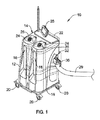
図1は、医療廃棄物流体収集及び廃棄システムの、又は、このシステムと共に使用するための、医療廃棄物流体収集カート10の斜視図である。いかなる形であれ限定的であることを意図されていない例示的な医療廃棄物流体収集及び廃棄システムが、例えば、全体が参照により本明細書に組込まれる「医療廃棄物流体収集及び廃棄システム」という題の2008年10月6日出願の米国特許出願第12/245,966号、現在の米国特許第8,292,857号の中で開示されている。
FIG. 1 is a perspective view of a medical waste
いくつかの場合、医療廃棄物流体収集カート10は、上部14、底部16及び上部14と底部16との間に延在する側面を有する、ハウジング12を含んでいてよい。少なくとも部分的にハウジング12内に位置付けされるか、そうでなければカート10上に位置付けされているのは、1つ以上の流体収集キャニスタ又はコンテナ18(例えばシリンダ又は他のキャニスタ又はコンテナ)であり得る。図1には2つのコンテナ18が示されているが、医療廃棄物流体収集カート10は、代替的な数のコンテナを含んでいてよく、例えば医療廃棄物流体収集カート10は、所望される場合、1つのコンテナ、3つのコンテナ、4つのコンテナ又は別の数のコンテナを含むように構成されてよい。
In some cases, the medical waste
医療廃棄物流体収集カート10のハウジング12は、例えばキャスタ20上に組付けられてよい。キャスタ20は、使用中所望の場所まで移動させるための移動性をカート10に付与するカート10のステアリング能力を提供するために使用されてよい。キャスタ20は、いくつかの事例においてブレーキ機能部を含む。ハウジング12の上部14は、所望される場合、カートの移動及び/又は位置付けを補助するための取っ手22を含んでいてよい。その結果、医療廃棄物流体収集カート10を、手術室及び/又は他の所望の場所から、及び、その場所へ容易に押して出し入れすることができる。
The
いくつかの場合、コンテナ18の各々は、複数の対応する蓋24及び/又はマニホルド26の間において(例えば、コンテナの蓋に連結され得るマニホルドは、コンテナに対する流体アクセスを提供し得る)、可撓管(図示せず)を介して真空源まで連結されてもよい。蓋24及び/又はマニホルド26は、成型プラスチック又は他の材料で製造され得、使い捨てであってよい。
In some cases, each of the
真空源(例えば真空ポンプ)をカート10上に提供することができ、又は、例えば手術室内に提供された壁面吸引部と関連付けられた真空ポンプなどの医療設備中に具備された真空源に、管を連結することもできる。蓋24及び/又はマニホルド26上の真空ポートに、蓋24内及び/又はマニホルド26内の区画内に位置付けされた疎水性フィルタなどのフィルタが設けられてもよい。
A vacuum source (e.g., a vacuum pump) can be provided on the
図2は、真空ラインシステム200を描いている。真空ラインシステム200は、1つ以上の真空ポンプ202、1つ以上のフィルタ204、1つ以上の弁206及び1つ以上の前置フィルタ208を含んでいてよい。真空ポンプ202の起動に応じて、真空流が、1つ以上のコンテナ18から、真空ライン210を通って、矢印212の方向に、前置フィルタ208へ、弁(単数又は複数)206(例えばT字弁及び/又は他の弁)へ、さらなる任意の真空ライン210を通り、フィルタ(単数又は複数)204を通り、真空ポンプ(単数又は複数)202を通って外へと流れることができる。所望される通りに、真空システム200の任意の装置間に真空ライン210を挿入することができる。
FIG. 2 depicts a
いくつかの場合、吸引管における吸引力を調節するために、真空ラインシステム200内に吸引力調節器を使用することができる。吸引力調節器を利用する1つの場合においては、真空流を方向転換させて、吸引力調節器を通過させることができ、この吸引力調節器内で、真空流は、真空流の流路を収縮させることによって吸引圧力を調節する。このような場合、真空流は、吸引力調節器に到達し、その中を流れ、そこから退出するために、1つ以上の湾曲部を通過することが求められる可能性がある。このような湾曲部及び他の絞り部は、真空流を不必要に制約し、吸引圧力を低減させる場合がある。
In some cases, a suction force regulator can be used in the
図2に示された代替的構成では、吸引力調節器214は1つ以上の弁206(例えば一方向T字弁又は他の弁)と連通することができ、こうして真空流は直接吸引力調節器214を通過せず(すなわち吸引力調節器214を迂回し)、結果として、吸引力調節器により真空レベルを調節するために吸引力調節器内の1つ以上の湾曲部及び/又は絞り部を通過する必要がなくなる。このような構成において、吸引力調節器214は、破線矢印216の方向で真空流内に空気を抽気するように起動され得る抽気弁であってよい。吸引力調節器214は、起動された場合、吸引力調節器214からの空気と真空流との混合物を作り出して、真空ポンプ202の効率に影響を及ぼすことなく、吸引管における吸引圧力及び真空流速度を計算され意図された形で低減させることができる。吸引力調節器214は、必要に応じて、吸引圧力を調整するために、単一速度真空ポンプ又は可変速度真空ポンプと共に使用することができる。
In an alternative configuration shown in FIG. 2, the
患者の吸引管(例えば再利用型又は使い捨て型の吸引管)を、蓋24及び/又はマニホルド26上の1つの吸引ポートに連結することができる一方、1つ以上の追加のポートをキャップ又はカバーで覆うことができる。蓋24及び/又はマニホルド26は、患者の管と連結するための管ポスト又はポートを含むことができる。結果として、真空又は吸引力は、医療処置の間、コンテナから患者まで延在する吸引管を介してコンテナ内に流体を収集できるように、各コンテナ上で選択的に引き込まれる。医療廃棄物流体収集カート10の吸引及び他の機能は、コントローラを含み得る及び/又はコントローラに通信可能に結合され得る、ユーザインタフェース28(例えばタッチスクリーン)を介して制御可能である。
A patient suction tube (eg, a reusable or disposable suction tube) can be connected to one suction port on the
蓋24及び/又はマニホルド26を真空ポートに連結するために可撓管を使用することができ、吸引ライン又は管を蓋24又はマニホルド26の吸引ポートに連結でき、可撓管及び吸引ライン又は管の各々は、それらの中を少なくとも部分的に延在する管腔を含むことができる。いくつかの場合、吸引管が取付けられていない吸引ポートがあれば、それをカバー又はキャップで覆うことができる。動作中、真空源は、手術部位から除去された流体を吸引管の管腔内に通して除去された流体をコンテナ18内に堆積させるために、コンテナ18の内部に負圧を作り出すことができる。
A flexible tube can be used to connect the
医療廃棄物流体収集カート10が手術室処置において使用され、コンテナ18のうちの1つ以上の中に流体が収集された後、患者の吸引管を、コンテナの蓋24及び/又はマニホルド26から取り外すことができ、吸引が適用された各々のコンテナの蓋24又はマニホルド26のための全ての吸引ポートをカバー又はキャップで覆うことができる。次に、医療廃棄物流体収集カート10を、排液、洗浄、消毒、濯ぎ及び吸引収集状態への復帰のため、排出ステーションに隣接する位置まで転がすことができる。
After the medical waste
排出ステーションは、消毒液供給源、ポンプ、ドレンシステム及び/又は医療廃棄物流体収集カート10のコンテナを排液、洗浄及び消毒するための他の構成要素を格納するハウジングを含んでいてよい。排出ステーションは、例えば複合ホース29及びカプラ30を介して医療廃棄物流体収集カート10と連通してよい。カプラ30は、医療廃棄物流体収集カート10のレセプタクル32の内部に収容されてよい。排出ステーションからの洗浄用流体は、これらのコンテナ18を洗浄し消毒するためにコンテナ18の中に位置付けされた清浄又は噴霧ノズル(図13中の噴霧ノズル53を参照のこと)を伴うコンテナ18の中に送出され得る。
The discharge station may include a housing that contains a disinfectant source, a pump, a drain system, and / or other components for draining, cleaning, and disinfecting the medical waste
カートコンテナ18の排液、洗浄及び消毒が完了した時点で、医療廃棄物流体収集カート10上のレセプタクル32からカプラ30を取り外すことができ、こうして医療廃棄物流体収集カート10を再び手術室内へと転動して使用できるようになっている。カプラ30は、医療廃棄物流体収集カート10と排出ステーションとの間で単一の連結を行なうことができるようにする。これにより、排出ステーションへの医療廃棄物流体収集カート10の連結及び排出ステーションからの医療廃棄物流体収集カート10の連結解除が簡略化され迅速になる。医療廃棄物流体収集カート10及び排出ステーションがカプラ30を用いて連結される場合、1つ以上の通信リンクを用いて、医療廃棄物流体収集カート10のコントローラ及び排出ステーションのコントローラが通信できるようにすることが可能であり、こうしてユーザーは、ユーザインタフェース28又は他のユーザインタフェースを介して、排液作業、洗浄作業及び消毒作業の1つ以上を含め、両方を制御することができるようになる。
When draining, cleaning, and disinfecting the
図3は、図1の医療廃棄物流体収集カート10用の例示的コントローラ100のブロック図表現である。いくつかの場合、医療廃棄物流体収集カート10は、医療廃棄物流体収集カート10の1つ以上の機能を制御するための命令を処理する能力を有する1つ以上の構成要素を含んでいてよい。いくつかの場合、コントローラ100は、図1のユーザインタフェース28の内部に含まれていてよい。代替的に、又は付加的には、コントローラ100の1つ以上の構成要素を、ユーザインタフェース28とは別個に医療廃棄物流体収集カート10上に提供及び/又は組付けすることができる。コントローラ100は、1つ以上のメモリユニット106、108(又はコントローラ100から遠隔に位置設定されたメモリ)、入出力ブロック110、データポート112、ユーザインタフェース114及び/又は通信インタフェース116を含むコントローラ100の1つ以上の構成要素にデータバス104を介して通信可能に結合され得るプロセッサ102(例えばマイクロプロセッサ、マイクロコントローラなど)を含むことができる。いくつかの場合、ユーザインタフェース114は、ユーザーに対して1つ以上のスクリーン118を表示するように構成されてよい。
FIG. 3 is a block diagram representation of an
プロセッサ102は、医療廃棄物流体の収集及び/又は収集された医療廃棄物流体の廃棄を制御又は少なくとも部分的に制御する、制御アルゴリズムを用いて動作することができる。プロセッサ102は、例えば、ユーザーにより実時間で規定され得る、及び/又は、メモリ106、108若しくは他のメモリなどの中で予め設定され得る、1つ以上の真空レベル及び/又は流体流速を用いて、医療処置の間に手術部位からの医療廃棄物流体を収集するためのアルゴリズムにしたがって、動作することができる。
The processor 102 may operate using a control algorithm that controls or at least partially controls the collection of medical waste fluid and / or disposal of the collected medical waste fluid. The processor 102 may use, for example, one or more vacuum levels and / or fluid flow rates that may be defined in real time by a user and / or preset in a
一実施例において、プロセッサ102は、オペレーティングシステム(例えばWindows(登録商標)、OSX、iOS、Android、Linux(登録商標)、Unix(登録商標)、GNUなど)、又は、例示的埋込み型オペレーティングシステム(例えばQNX、Nia−gara AX、Windows(登録商標) CEなど)を用いて、アルゴリズム(単数又は複数)を動作させるように構成されていてよい。いくつかの場合、コントローラ100は、タイマー(図示せず)を含んでいてよい。タイマーは、プロセッサ102と一体化されていてもよいし、又は、別個の構成要素として提供されてもよい。
In one embodiment, processor 102 may be an operating system (eg, Windows®, OSX, iOS, Android, Linux®, Unix®, GNU, etc.) or an exemplary embedded operating system (such as For example, the algorithm (s) may be operated using QNX, Nia-gara AX, Windows (registered trademark) CE, or the like. In some cases, the
例示的コントローラ100のメモリ106、108は、プロセッサ102に対し通信可能に結合されてよい。メモリ106、108は、上述の制御アルゴリズム、電力監視アルゴリズム、医療廃棄物流体収集及び廃棄システムの構成、設定点、真空レベル、流量レベル、フラグ、インジケータ、診断限界、ルックアップテーブル、検知されたパラメータ相関関係などの所望されるあらゆる情報を記憶するために使用され得る。メモリ106、108は、RAM、ROM、EPROM、フラッシュメモリ、ハードドライブなどを非限定的に含む任意の好適なタイプの記憶装置であってよい。いくつかの場合、プロセッサ102は、メモリ106、108内部に情報を記憶することができ、その後、記憶された情報を取り出すことができる。
The
いくつかの場合、コントローラ100は、医療廃棄物流体収集カート10の1つ以上の構成要素から1つ以上の信号を受信しかつ/又は医療廃棄物流体収集カート10の1つ以上の構成要素に1つ以上の信号を提供するための入出力ブロック(I/Oブロック)110を含むことができる。例えばI/Oブロック110は、1つ以上の通信経路120を介して、1つ以上のライト34(例えばコンテナ18と関連付けられたコンテナライト)、1つ以上の切換え装置36(例えばソレノイド、継電器、トランジスタなど)、「洗浄」弁、「排液」弁及び/若しくは「通気」弁の1つ以上の構成要素を含む弁駆動システム38の1つ以上の構成要素(例えばモータ、弁など)、1つ以上のセンサ40(例えばライトセンサ、圧力センサ、レベルセンサ、流量センサなど)、ポンプ42(例えば真空ポンプ、排出ポンプなど)、並びに/又は、1つ以上の他の構成要素に、信号を提供しかつ/又はそこから信号を受信するように構成され得る。I/Oブロック110は、例えば1つ以上の端子ネジを介した有線通信、及び/又は、例えば無線通信インタフェースを介した無線通信用に構成されてよい。いくつかの場合、I/Oブロック110は、特定の医療プロセスに結び付けられる他のセンサ及び/又は装置と通信するために使用可能である。
In some cases, the
いくつかの場合、図3に例示されているように、コントローラ100はデータポート112を含むことができる。データポート112は、Bluetooth(登録商標)、WiFi(登録商標)、Zigbee(登録商標)又は他の任意の無線プロトコルなどの無線プロトコル用の無線ポートであってよい。他の場合において、データポート112は、シリアルポート、ARCNETポート、パラレルポート、CAT5ポート、USB(ユニバーサルシリアルバス)ポートなどの有線ポートであってよい。いくつかの場合、データポート112は、有線ネットワーク又は無線ネットワークを介して使用され得る1つ以上の通信プロトコル、例えばEthernet(登録商標)、BACNet、LONtalk、などを使用することができる。いくつかの事例において、データポート112はUSBポートであってよく、USBフラッシュドライブ又は他のいくつかのデータソースから情報をダウンロード及び/又はアップロードするために使用可能である。所望される通り、他の遠隔装置も同様に利用可能である。
In some cases,
データポート112は、プロセッサ102と通信するように構成されてよく、所望の場合には、プロセッサ102に情報をアップロードしプロセッサ102から情報をダウンロードするために使用され得る。アップロード及び/又はダウンロードされ得る情報には、例えば、動作パラメータ(例えば真空レベル、流速、体積レベル、流体濃度レベルなど)、測定相関関係、ルックアップテーブル及び/又はアルゴリズムが含まれ得る。いくつかの事例において、データポート112を使用して、先に作成された構成及び/又はソフトウェア更新をコントローラ100にアップロードし、プログラミングプロセスを加速させることができる。
The
いくつかの場合、データポート112は、分析及び/又は別の装置への転送のために、メモリ106、108内に記憶されたデータをダウンロードするために使用されてよい。例えば、所望される通り、USBメモリスティック(サムドライブ又はジャンプドライブと呼ばれる場合もある)、パーソナルコンピュータ、ラップトップ、iPAD(登録商標)又は他のタブレットコンピュータ、PDA、スマートホン又は他の装置などの遠隔装置に対して、1つ以上の記憶された流速及び/若しくは真空レベル、故障及び/若しくは警報記録、検知されたデータ、並びに/又は検知されたデータに基づく計算をダウンロードするためにデータポート112を使用することができる。いくつかの場合、データは、所望される場合、MS EXCEL(登録商標)、MS WORD(登録商標)、テキスト、XML、及び/又はAdobe PDF(登録商標)ファイルに変更可能であり得る。
In some cases,
図3の例示的実施形態において、ユーザインタフェース114は、コントローラ100が情報を表示及び/又は要請し、かつコントローラ100との間の1つ以上のユーザー相互作用を受容することを可能にする任意の好適なユーザインタフェースであってよい。例えば、ユーザインタフェース114は、ユーザーが真空レベル、患者情報、処置の開始/終了時間、流速、医学的応用タイプなどのデータを入力できるようにすることができる。いくつかの場合、ユーザインタフェース114はディスプレイ及び個別のキーパッドを含むことができる。ディスプレイは、任意の好適なディスプレイであってよい。いくつかの場合、ディスプレイは液晶ディスプレイ(LCD)、いくつかの場合、固定型セグメントディスプレイ又はドットマトリクスLCDディスプレイを含むか又はそれであってよい。所望される場合、ユーザインタフェース114は、ディスプレイ及びキーパッドの両方として機能するタッチスクリーンLCDパネルであってよい。いくつかの場合、タッチスクリーンLCDパネルは、所望される場合には、一定数の動作パラメータについて値を要請するように及び/又はこのような値を受信するように適応されていてよい。いくつかの場合、ユーザインタフェース114は、任意にはメモリ108を含むことができる。いくつかの場合、ユーザインタフェース114は、所望される流速、真空レベル及び/又はパラメータを選択する上で使用するために、1つ以上の電気機械式入力装置(例えばスイッチ、電位差計、回転ダイアル、押しボタンなど)を含むことができる。
In the exemplary embodiment of FIG. 3, the
一実施例において、ユーザインタフェース114は、データバス104を介して、プロセッサ102及び/又はメモリ106、108に通信可能に結合されたグラフィカルユーザインタフェースを含むことができる。ユーザインタフェース114は、医療廃棄物流体収集カート10及び/又は排出ステーションの1つ以上の機能をユーザーが監視及び/又は制御できるようにするように構成されてよい。ユーザインタフェース114は、ユーザーに対して情報を提供するために使用可能である1つ以上のスクリーン118を含むことができる。いくつかの場合、タッチスクリーン、キーパッド、医療廃棄物流体収集カート10上のボタン及び/又は別の電気機械式入力装置(例えばダイヤルインタフェース)を介して、ユーザーから、真空レベル、流速及び/又は他の情報の入力を要請するために、グラフィカルユーザインタフェースを使用することができる。
In one embodiment,
通信インタフェース116は、コントローラ100が、例えば通信リンク122を介して1つ以上の他の装置124と通信できるようにするための1つ以上の通信インタフェースを含むことができる。例えば、通信インタフェース116は、カプラ30を介して医療廃棄物流体収集カート10が排出ステーションと通信できるようにする通信インタフェースを含むことができる。いくつかの場合、通信リンク122と関連付けられた1つ以上のコネクタがカプラ30内に含められていてよい。他の場合において、通信リンク122は、カプラ30とは別個であってよい。いくつかの場合、通信インタフェース116は、Ethernet(登録商標)ポート、無線ポート、RS−232ポート、RS−422ポート、RS−485ポートなどの1つ以上の有線及び/又は無線通信インタフェースを含むことができる。このような場合、通信インタフェース116は、例えば認定されたユーザーにより、通信リンク122を介して、データ入力、再プログラミング、アップグレーディング、デバッギング及び/又は他のオペレーションを遠隔で行なうことができるようにすることができる。
The communication interface 116 may include one or more communication interfaces that allow the
図4は、コンテナ18、蓋アセンブリ23及びベース44を含む例示的コンテナアセンブリ17である。コンテナ18は、底部19a及び上部19bを伴う本体19を有することができ、ベース44は、本体19の底部19aに隣接して位置設定され得、蓋アセンブリ23は、本体19の上部19bに隣接して位置設定されてよい。
FIG. 4 is an
図5は、コンテナアセンブリ17の分解図である。図5に示されているように、蓋アセンブリ23は蓋24及び蓋リング25を含むことができる。例示的に、蓋リング25は、本体19の上部19bと係合でき、蓋24は蓋リング25と係合してコンテナ18内への開口部の少なくとも一部分を閉鎖し、コンテナ18の内部への選択的アクセスを提供することができる。
FIG. 5 is an exploded view of the
コンテナ18は、流動性廃棄物収集カート10のハウジング12の内部に少なくとも部分的に適合するように構成された任意の形状及びサイズであり得、そうでなければカート10上に位置付けされてよい。図5に示されているように、コンテナ18の本体19は、少なくとも部分的に開放した端部(例えば底部19a及び上部19b)及び各端部間に延在する管腔19cを伴う、円筒形状(例えば、丸形及び円形横断面を有する形状)であり得る。代替的に又は付加的には、コンテナ18の本体19は、円とは異なる断面形状、例えば、方形、矩形、楕円形又は他の2次元形状を有することができる。いくつかの場合、本体19の底部19aは、コンテナ18の本体19と、別個に連結された、一体として連結された、又は、モノリシックに形成された、ベース(例えばベース44又は他のベース)を含むことができる。ベース44が本体19に連結される場合、非限定的に、接着剤連結、圧力嵌め連結、ネジ込み連結、差し込み(bayonet)連結、ツイストロック連結及び/又は1つ以上の他の恒久的又は可逆的連結技術を含む任意の連結技術を用いて、ベース44を本体19に連結することができる。
The
いくつかの事例において、蓋アセンブリ23はOリング45を含むことができる。Oリング45は蓋リング25と係合し、蓋リング25がコンテナと係合しているときに、蓋リング25とコンテナ18(例えば本体19)との間に液密シールを作り出すことができる。Oリング45は、蓋リング25とコンテナ18との間の摩擦嵌め連結、ネジ込み連結、差し込み連結、ツイストロック連結及び/又は1つ以上の他の連結タイプをさらに容易にするように構成されてよい。
In some cases, the
蓋アセンブリは、マニホルド26を含んでいてよい。マニホルド26は、蓋24に対し解放可能に連結するように構成されてよい。いくつかの場合、マニホルド26は、使用後、蓋24から取り外されるように構成されていてよく、使い捨てであり得る。マニホルド26は、コンテナ18に対するアクセスを提供するため1つ以上のポートを含むことができる。一実施例において、1つ以上のポートは、管に連結するように構成され得、吸引管に連結するための1つ以上の吸引ポート、真空管に連結するための1つ以上の真空ポート、及び/又は、1つ以上の他のポートを含むことができる。
The lid assembly may include a manifold 26. The manifold 26 may be configured to releasably connect to the
マニホルド26は、1つ以上の方法で蓋24と係合するように構成されていてよい。マニホルド26は、ネジ込み連結、圧力嵌め連結、差し込み連結、ツイストロック連結、及び/又は、1つ以上の他の連結タイプを通して、蓋24に連結するか又は蓋24と係合することができる。いくつかの場合、気密又は密閉型シールをマニホルド26と蓋24との間に形成することができる。
ベース44は、上部部分46と底部部分48とを含むことができる。一実施例において、上部部分46の少なくとも一部は、コンテナ18の本体19の底部19aを通って、かつ本体19の管腔19cの内部に嵌合するようにサイズ決定され構成されてよい。本体19の底部19aは、ベース44の底部部分48上に載り及び/又は底部部分48の側面(単数又は複数)上に延在することができる。気密又は密閉型シールが、コンテナ18の本体19とベース44との間に形成され得る。
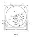
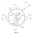
図6は、ベース44の上面斜視図である。図6に示されているように、ベース44は、上部部分46及び底部部分48を含むことができ、底部部分48は、上部部分46の設置面積幅(図11中のF1)と少なくとも同じか又はこれよりも広い設置面積幅(図11中のF2)を有することができる。代替的に、又は付加的には、上部部分46の設置面積幅の少なくとも一部分は、底部部分48の設置面積幅よりも広いものであり得る。上部部分46及び底部部分48は、モノリシックに形成されているか又は、共に一体として接合された2つ以上の部片であってよい。いくつかの場合、底部部分48は、コンテナ18をカート10に締結するための締結具を収容するための1つ以上の孔49を有することができる。
FIG. 6 is a top perspective view of the
ベース44の上部部分46は、内部表面50と、噴霧孔又は開口部52と、ドレン孔又は開口部54と、底部部分48から延在できかつ内部表面50の外周及び/又は上部部分46の外周を少なくとも部分的に画定する上部を有することのできる周囲壁56と、を有することができる。噴霧開口部52は、コンテナ18の使用の前、間及び/又は後にコンテナ18内に清浄用流体及び他の流体を注入することを可能にすることができる。ドレン開口部54は、ドレン開口部に連結されたドレン及び/又はホースを通した固体(骨片、凝血隗など)及び流動性廃棄物のコンテナ18からの除去を容易にするように構成されていてよい。
The
噴霧開口部52は少なくとも部分的に、ベース44から又はベース44を貫通してコンテナ18の内部に向って延在する延長部分51(例えばポスト又は他の機能部)によって画定され得、噴霧開口部52は、延長部分51を通って第1の端部52aから第2の端部52bまで延在することができる。噴霧開口部52の第1の端部52aは、ベースが本体19の一端部を取り囲んでいる場合、コンテナ18の内部に位置設定され得る。第1の端部52aは、噴霧ノズル53(図13参照)を含むことができ、又はこのノズルを収容するように構成されていてよく、ここで清浄用流体又は他の流体は、噴霧開口部52を通って、コンテナ18の内部に位置付けされた噴霧ノズル53の上部部分から外に移行することができる。いくつかの場合、噴霧ノズル53は、ネジ込み連結、摩擦嵌め連結、差し込み連結、ツイストロック連結、接着剤連結及び/又は1つ以上の他の連結のうちの1つ以上を通して、第1の端部52aに連結することができる。噴霧開口部52の第2の端部52bは、噴霧開口部52に対し流体(例えば清浄用流体又は他の流体)を通すためのホースに連結するように構成されていてよい。
The
ベース44は、噴霧開口部52及び/又はベース44の中央部分から周囲壁56に向かって及び/又はこの周囲壁まで延在する半径方向出っ張り(ledge)47及び/又は半径方向壁58を含むことができる。半径方向出っ張り47及び/又は半径方向壁58は、実質的に線形的に又は非線形的に(例えば曲線形的、段階的など)に半径方向に延在することができる。一実施例において、図6に示されているように、半径方向壁58は、曲線的に半径方向に延在し得る。半径方向出っ張り47は、丸味を帯びていてよく、及び/又は、一体となった2つ以上の表面によって形成されていてもよい。
The
図6に示されているように、ベース44の内部表面50は、ベース44の半径方向壁58の第1の側58a(例えば図6に示されている凸状側)から、ドレン開口部54及び第1の側58aとは反対の半径方向壁58の第2の側58b(例えば、図6に示されている凹状側)に向かう経路内に又は経路に沿って、延在することができる。内部表面50は、ドレン開口部54に隣接する場所、半径方向壁58の第2の側58bに隣接する場所まで延在し及び/又は半径方向出っ張り47の下を延在することができる。内部表面50の経路は螺旋状であってよく、その一例が図中で示されている。内部表面50がそれに沿って延在し得る螺旋経路は、出発点からドレン開口部54に隣接する終点まで回転点の周りで少なくとも部分的に下り勾配になっている、巻回された、傾斜付きの、渦巻状の及び/又は別の形で構成された経路であり得る。図中の内部表面50は、円筒形の周囲をたどる螺旋経路に沿って延在するものの、内部表面50は、円筒以外の形状(例えば直平行六面体、立方体、角柱、角錐、卵形など)の周囲をたどる螺旋経路に沿って延在することができる。
As shown in FIG. 6, the
いくつかの場合、内部表面50の経路は、延長部分51の周り、噴霧開口部52の周り、及び/又はベース44の中央部分の周りに延在することができる。内部表面50の経路が延長部分51及び/又は噴霧開口部52の周りに延在している事例においては、内部表面50は、全体が噴霧開口部52の第1の端部52aの下方にあってもよい、内部表面50は、第1の端部52aのレベルで開始し、第1の端部52aの下方に延在してもよい、内部表面50は、少なくとも部分的に第1の端部52aの上方に及び少なくとも部分的に第1の端部52aの下方にあってもよい、内部表面50は、第1の端部52aの上方から第1の端部52aのレベルまで延在してもよい、又は、内部表面50は、全体が第1の端部52aの上方にあってもよい。ベース44の中央部分は、周囲壁56から離隔され、ベース44がコンテナ18の本体19の一端部を取り囲んでいる場合に、ベース44を通って延在するコンテナ18の中央軸に向かって位置付けされたベース44の一部分とみなされてよい。いくつかの事例において、ベース44の中央部分は、コンテナ18の内部において中心に配置される必要はない。いくつかの事例において、延長部分51の長手方向軸は、コンテナ18の内部において中心に配置されてもよい一方で、他の事例においては、延長部分51の長手方向軸は、コンテナ18の中心からずらされていてよい。
In some cases, the path of the
内部表面50は、ドレン開口部54に向かって角度付けされるか又は下り勾配になっていてよい。例えば、内部表面50は、半径方向壁58の第1の側58aに隣接する最上点から、ドレン開口部54及び/又は半径方向壁58の第2の側58bに隣接する場所まで、螺旋経路に沿って下り勾配になっていてよい。いくつかの場合、内部表面50の下り勾配は、ドレン開口部54又はそれに隣接したところで終了し得る。このような場合、半径方向壁58の第2の側58bとドレン開口部54の間に延在する内部表面50は、水平であるか、又はドレン開口部54に向かう下り勾配で角度付けされていてよい(図7参照)。
The
内部表面50の下り勾配(単数又は複数)は、連続又は不連続であってよい。例えば、図6にあるように、内部表面50の下り勾配は連続的であり得る。代替的には、内部表面50は、階段の形に又は螺旋経路に沿って平坦であるか又は下り勾配で角度が付いている斜面(runs)を有する他の不連続な機能部へと分離されてよい。いくつかの場合、内部表面50の下り勾配角度は、螺旋経路に沿って一貫していてよい。代替的には、内部表面50の下り勾配角度は、螺旋経路に沿って増大又は減少してよい。
The descending slope (s) of the
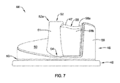
図7は、半径方向壁58の第2の側58bに隣接して終結する内部表面50の螺旋経路を示すベース44の側面図である。図7において、螺旋経路に沿った内部表面50の下り勾配は、ドレン開口部54又はそれに隣接する場所に向かって下っている。さらに、内部表面50は、半径方向壁の第2の側58bからドレン開口部54に隣接する場所に向かって下り勾配になっているものとして、図7で描かれている。内部表面50のこのような下り勾配(単数又は複数)は、ドレン開口部54内へ及びレベルセンサ57から離れるように(例えば、図13に示されているように、固体(例えば固体の集積又は障害物)がレベルセンサ57と干渉し半径方向壁に隣接して位置付けされるのを妨げ、ドレン開口部54を通した固体及び液体の排液を容易にするため、半径方向壁58に隣接して位置付けされ半径方向壁58に沿って移動可能であるレベルセンサ57のフロート59から離れるように)固体を誘導するのを容易にし、以下でさらに論述する通り、収集された流動性廃棄物の排液を促進することができる。
FIG. 7 is a side view of the base 44 showing the helical path of the
ベース44は、Oリング(図示せず)を収容するように構成された刻み目60を含むことができる。ベース44がコンテナ18の本体19と連結するとき、刻み目60及び付随するOリングは、ベース44と本体19との間に密閉型シールを作り出すことを容易にすることができる。
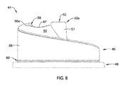
図8は、図7に描かれた側面図とは反対側のベース44の側面図である。図8は半径方向壁58の第1の側58aに隣接する場所から螺旋経路に沿って下り勾配になっている内部表面50を示す。
FIG. 8 is a side view of the base 44 opposite to the side view depicted in FIG. FIG. 8 shows the
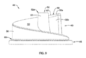
図9は、図7及び図8に描かれた側面図から90度回転させられたベース44の側面図である。図9は、半径方向壁58の第1の側58aに隣接する場所から螺旋経路に沿って下り勾配になっている内部表面50を示す。
FIG. 9 is a side view of the base 44 rotated 90 degrees from the side views depicted in FIGS. FIG. 9 shows the
図10は、図9に描かれた側面図の反対側のベース44の側面図である。図10は、噴霧開口部52を中心とする螺旋経路に沿った内部表面50の下り勾配を示す。
FIG. 10 is a side view of the base 44 opposite the side view depicted in FIG. FIG. 10 shows the downward slope of the
図11は、ベース44の上面図である。図11の上面図は、半径方向壁58の第1の側58aから半径方向壁58の第2の側58bまで噴霧開口部52の周りで螺旋経路に沿って延在する内部表面50を描いている。いくつかの事例において、内部表面50の幅は、螺旋経路に沿って一定であり続けてよい。代替的には、内部表面50の幅は、螺旋経路に沿って増大又は減少し得る。図11を見れば分かるように、内部表面50は、螺旋経路の開始点(すなわちドレン開口部54から最も遠い部分)に隣接する幅W1が螺旋経路の終点(すなわち、ドレン開口部54に最も近い部分)に隣接する幅W2よりも大きいことから、螺旋経路に沿って先細りになっている。内部表面50は、コンテナ18の流体中の固体が螺旋経路に沿ってドレン開口部54に向かって誘導されるにつれて、これらの固体をコンテナ18の本体19から離れて内部表面50の中央へと誘導することを容易にするために、先細りになっていてよい。噴霧開口部52は、内部表面50の先細りを容易にするために及び/又は他の目的のために、ベース44の中央軸からずらされていてよい。
FIG. 11 is a top view of the
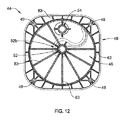
図12は、図11中に描かれた上面図とは反対側のベース44の底面図である。締結具を収容するように構成された噴霧開口部52、ドレン開口部54及び孔49は、ベース44を貫通して延在し得る。ベース44内部の1つ以上の補強機能部63(明確さのため図12では厳選した数個の補強機能部63だけが、ラベル付けされている)が、ベース44の製造中及びベース44の使用中、ベース44を補強する目的で提供されている。
FIG. 12 is a bottom view of the base 44 opposite to the top view drawn in FIG. 11. A
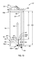
図13は、ライン13−13に沿って切り取った図4のコンテナアセンブリ17の断面図である。図13は、螺旋経路に沿った内部表面50の下り勾配を描いている。例えば、破線D1は、螺旋経路の開始点の又はそれに隣接する内部表面50から本体19の上部周縁までの距離を表わし、破線D2は、螺旋経路の終点の又はそれに隣接する内部表面50から本体19の上部周縁までの距離を表わす。ここでD1は、D2の距離よりも短い距離である。
13 is a cross-sectional view of the
液面センサ57は図13に描かれている。液面センサ57は、ベース44、蓋アセンブリ23及び本体19の1つ以上から延在していてよいが、図13に示されたレベルセンサ57は、蓋リング25のホルダー55から半径方向壁58及びドレン開口部54に隣接するベース44に向かって延在する。
The
レベルセンサ57は、コンテナ18内の材料の量を測定する能力を有する任意のタイプのレベルセンサ57であってよい。図13では、レベルセンサ57は、コンテナが材料で満たされるか又はコンテナから材料が排液されるにつれて、細長い部材61に沿って浮動するように構成されたフロート59を含むことができる。レベルセンサ57は、レベルセンサ57上又はそれに隣接するマーキング及び細長い部材61に沿ったフロート59の位置に基づいて、コンテナ18内の材料レベルの視覚的標示を提供することができる。代替的に又は付加的に、レベルセンサ57は、コントローラ100又は他のコントローラと通信することができ、液面の測定値はユーザインタフェース28又は他のユーザインタフェース上に表示され得る。
The
図14は、コンテナアセンブリ17のコンテナ18用の代替的ベース(例えばベース344)の上面斜視図である。図14に示されているように、ベース344は、上部部分346及び底部部分348を含むことができる。上部部分346及び底部部分348は、モノリシックに形成されてもよい、又は、一体的に共に接合された2つ以上の部品であってもよい。いくつかの場合、底部部分348は、コンテナ18をカート10に締結するための締結具を収容する目的で1つ以上の孔349を有することができる。
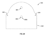
FIG. 14 is a top perspective view of an alternative base (eg, base 344) for
ベース344の上部部分346は、内部表面350と、噴霧孔又は開口部352と、ドレン孔又は開口部354と、底部部分348から延在できかつ内部表面350の外周及び/又は上部部分346の外周を少なくとも部分的に画定する上部を有することのできる周囲壁356と、を有することができる。噴霧開口部352は、コンテナ18の使用の前、間及び/又は後にコンテナ18内に清浄用流体及び他の流体を注入することを可能にすることができる。ドレン開口部354は、ドレン開口部354に連結されたドレン及び/又はホースを通した固体(骨片、凝血隗など)及び流動性廃棄物のコンテナ18からの除去を容易にするように構成されていてよい。
The
噴霧開口部352は、少なくとも部分的にベース344を貫通して又はベース344からコンテナ18の内部内に延在する延長部分351(例えばポスト又は他の機能部)によって画定され得、延長部分351を通って第1の端部352aから第2の端部352b(図20参照)まで延在することができる。噴霧開口部352の第1の端部352aは、ベース344が本体19の一端部を取り囲んでいる場合、コンテナ18の内部に位置設定され得る。第1の端部352aは、噴霧ノズル53を含むことができ又は収容するように構成されていてよく、ここで清浄用流体又は他の流体は、噴霧開口部352を通って、コンテナ18の内部に位置付けされた噴霧ノズル53の上部部分から外に移行することができる。いくつかの場合、噴霧ノズル53は、ネジ込み連結、摩擦嵌め連結、差し込み連結、ツイストロック連結、接着剤連結及び/又は1つ以上の他の連結のうちの1つ以上を通して、第1の端部352aに連結することができる。噴霧開口部352の第2の端部352bは、噴霧開口部352に対し流体(例えば清浄用流体又は他の流体)を通すためのホースに連結するように構成されていてよい。
The
ベース344は、出っ張り347及び/又は壁358を含むことができ、ここで壁358は、内部表面350からベース表面355(例えば液体レベルを測定する起点である表面)まで延在することができる。出っ張り347及び/又は壁358は任意の形状を形成し得る。一実施例においては、図14に示されているように、出っ張り347及び壁358は、曲線又は丸味のある形状を有し、ドレン開口部354に隣接する場所まで及びから延在することができる。
The base 344 can include a
図14に示されているように、ベース344の内部表面350は、少なくとも部分的に周囲壁356によって画定される外周囲及び少なくとも部分的に出っ張り347又は壁358によって画定されている内周囲を有することができる。内部表面350は、ドレン開口部354及び/又はベース表面355に隣接する場所まで延在することができる。内部表面350は、収集された医療廃棄物をドレン開口部354に向かって誘導し、医療廃棄物の固体をベース表面355から離れるように誘導する経路をたどることができる。この経路は、ドレン孔に向かって下り勾配となり得、任意の形状(例えば図14に示されているような傾斜付き三日月形若しくは円形形状、又は他の形状)をとることができる。
As shown in FIG. 14, the
いくつかの場合、内部表面350の経路は、延長部分351の周り、噴霧開口部352の周り、及び/又は、ベース344の中央部分の周りに延在することができる。内部表面350の経路が延長部分351及び/又は噴霧開口部352の周りに延在している事例においては、内部表面350は、全体が噴霧開口部352の第1の端部352aの下方にあってもよい、内部表面350は、第1の端部352aのレベルで開始し、第1の端部352aの下方に延在してもよい、内部表面350は、少なくとも部分的に第1の端部352aの上方及び少なくとも部分的に第1の端部352aの下方にあってもよい、内部表面350は、第1の端部352aの上方から第1の端部352aのレベルまで延在してもよい、又は、内部表面350は、全体が第1の端部352aの上方にあってもよい。ベース344の中央部分は、周囲壁356から離隔され、ベース344がコンテナ18の本体19の一端部を取り囲んでいる場合にベース344を通って延在するコンテナ18の中央軸に隣接するベース344の一部分とみなされてよい。ベース344の中央部分の延長部分351は、コンテナ18の内部において中心に配置される必要はない。例えば、いくつかの事例において、延長部分351の長手方向軸は、ベース344の内部において中心に配置されてもよい一方で、他の事例においては、延長部分351の長手方向軸は、ベース344の中心からずらされていてよい。
In some cases, the path of the
上述の通り、内部表面350は、ドレン開口部354に向かって、下り勾配になっていてよく、内部表面350の下り勾配(単数又は複数)は、連続又は不連続であってよい。例えば、図14にあるように、内部表面350の下り勾配は連続的であり得る。代替的には、内部表面350は、階段の形に、又は、内部表面350の経路に沿って平坦である若しくは下り勾配で角度が付いている斜面を有する他の不連続な機能部に、分離されてよい。いくつかの場合、内部表面350の下り勾配角度は、ドレン開口部354に向かって経路に沿って一貫していてよい。代替的には、内部表面350の下り勾配角度は、ドレン開口部354に向かって経路に沿って増大又は減少してよい。
As described above, the
図15は、ドレン開口部354の第1の側に及び第2の側において、ドレン開口部354に隣接して下り勾配となり終結する内部表面350の経路を示すベース344の側面図である。内部表面350のこのような下り勾配(単数又は複数)は、ドレン開口部354内へ、並びに、ベース表面355及び壁358に隣接して位置付け可能であるレベルセンサ57から離れるように(例えば、図13に示されているように、固体(例えば固体の集積又は障害物)がレベルセンサ57と干渉するのを妨げドレン開口部354を通した固体及び液体の排液を容易にするためにレベルセンサ57のフロート59から離れるように)固体を誘導するのを容易にすることができる。
FIG. 15 is a side view of the base 344 showing the path of the
ベース344は、Oリング(図示せず)を収容するように構成された刻み目360を含むことができる。ベース344がコンテナ18の本体19と連結するとき、刻み目360及び付随するOリングは、ベース344と本体19との間に密閉型シールを作り出すことを容易にすることができる。
The base 344 can include a
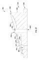
図16は、図15に描かれている側面図と反対側のベース344の側面図である。図16は、上部部分346と底部部分348を示し、上部部分346には刻み目360が形成されている。図16に示されているように、上部部分346の周囲壁356は、ベース344の反対側に向かって下り勾配になっていてよい。
FIG. 16 is a side view of the base 344 opposite the side view depicted in FIG. FIG. 16 shows a
図17は、図15及び16に描かれている側面図から90度回転させられたベース44の側面図である。図17は、ベース344の上部部分346の幅に沿って下り勾配になっているベース344の周囲壁356を示している。
FIG. 17 is a side view of the base 44 rotated 90 degrees from the side view depicted in FIGS. 15 and 16. FIG. 17 shows the
図18は、図17に描かれている側面図と反対側のベース344の側面図である。図18は、ベース344の上部部分346の幅に沿ったベース344の周囲壁356の下り勾配を示している。
FIG. 18 is a side view of
図19は、ベース344の上面図である。図19の上面図は、周囲壁356の上部と出っ張り354との間のベース表面355の周り及び噴霧開口部352の周りで経路に沿って延在する内部表面350を描いている。いくつかの事例において、内部表面50の幅は、ドレン開口部354に向かって経路に沿って一定であり続けてよい。代替的には、内部表面350の幅は、経路に沿って増大又は減少し得る。図19を見れば分かるように、内部表面350は、経路の開始点(例えばドレン開口部354から最も遠い部分)に隣接する幅W1’が経路の終点(例えば、ドレン開口部354に最も近い部分)に隣接する幅W2’よりも大きいことから、経路に沿って先細りになっていてよい。内部表面350は、コンテナ18の流体中の固体が経路に沿ってドレン開口部354に向かって誘導されるにつれて、これらの固体をコンテナ18の本体19から離れて内部表面350の中央へと誘導することを容易にするために、先細りになっていてよい。噴霧開口部352は、ベース344の中央軸にあるか又はこの軸からずらされていてよい。
FIG. 19 is a top view of the
図20は、図19中に描かれた上面図とは反対側のベース344の底面図である。締結具を収容するように構成された噴霧開口部352、ドレン開口部354及び孔49は、ベース344を貫通して延在し得る。
FIG. 20 is a bottom view of the base 344 opposite to the top view depicted in FIG. A
図21は、図19中のライン21−21に沿って切り取ったベース344の断面図である。図21に示されているように、内部表面350は、ドレン開口部354に向かって下り勾配になり、噴霧開口部352及びベース表面355の周りに延在する。ドレン開口部354に向かって延在するにつれて内部表面350の幅の変化を示すことに加え、内部表面350は、非線形表面(例えば図21に示されている丸味のある表面、又は、他の非線形表面)を含むことができる。非線形表面は、表面350が経路に沿ってドレン開口部354に向かって延在するにつれて、コンテナ18内の固体医療廃棄物を内部表面350の中央部分に向かって誘導するように構成されていてよい。このような非線形表面は、本体19に沿った固体の集積を防ぐため及び/又は他のメリットのため、収集された医療廃棄物中の固体をコンテナ18の本体19から離れるように移動させやすくすることができる。
21 is a cross-sectional view of the base 344 taken along line 21-21 in FIG. As shown in FIG. 21, the
図22は、図19中のライン22−22に沿って切り取られたベース344の断面図である。図22は、周囲壁356の上部と、出っ張り347と、の間に延在する幅を有する、内部表面350を示す。図21の場合と同様に、内部表面350は、コンテナ18の本体19に沿った固体の集積の防止を容易にするため、ベース表面355及びレベルセンサ57から離れるようにかつドレン開口部354に向かって固体医療廃棄物を誘導するため、及び/又は他の利益のため、その幅を横断して非線形であってよい。
22 is a cross-sectional view of
図14−図22に描かれているベース344は、ベース44のものと類似の形式で、コンテナアセンブリ17内で利用可能である。こうして、コンテナ18内にベース344が含まれている場合、ベース344の内部表面350の経路の上部は、内部表面350の(例えばドレン開口部354に隣接する)経路の底部からコンテナ18の本体19の上部までの距離より短い、コンテナ18の本体19の上部までの距離を有することができる。
The base 344 depicted in FIGS. 14-22 can be utilized within the
図23は、コンテナアセンブリ17の蓋アセンブリ23の斜視図である。蓋アセンブリ23は、蓋24及び蓋リング25を含んでいてよい。蓋24は、マニホルド26を収容するように構成され得る開口部62を含むことができる。蓋24は、非限定的に摩擦嵌め連結、ネジ込み連結、差し込み連結、ツイストロック連結、及び/又は、1つ以上の他の連結機構を介したものを含む任意の方法で、開口部62内に挿入されるマニホルドに連結することができる。図23に示された実施例では、蓋24は、開口部62の一部としての、又は、開口部62から延在する、1つ以上のタブ開口部64(例えば、図23に示されている通りの2つのタブ開口部64)を含むことができる。タブ開口部64は、マニホルド26と蓋24との間の連結を容易にするために、マニホルド26の側面から延在するタブを収容するようにサイズ決定され及び/又は他の形で構成される。
FIG. 23 is a perspective view of the
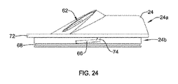
図24は、蓋24の側面図である。蓋24は、外部部分24a及び内部部分24bを有していてよく、ここで外部部分24aは、カート10の外からアクセス可能であってよく、内部部分24bは、最終的に蓋リング25内に部分的に収容されるように構成されていてよい。内部部分24bは、蓋リング25の係止用機能部(例えば、溝70)の中での収容又はそれとの係合のための係止用機能部(例えば、フランジ66)を含むことができ、係止用機能部は、蓋24の回転に応じたコンテナ18への蓋24の係合及びそこからの係合解除を容易にすることができる。任意には、蓋24の内部部分24bは、蓋24と蓋リング25との間の密閉型シールの創出を容易にすることのできるOリングを収容するための刻み目68を含んでいてよい。
FIG. 24 is a side view of the
蓋24及び蓋リング25は、蓋24及び蓋リング25の1つ以上の上の係止用機能部を利用する係止機構を介して、互いに係合することができる。蓋24と蓋リング25との間の係止機構は、圧力嵌め機構、差し込み係止機構、ツイストロック機構、ネジ込み機構及び/又は1つ以上の他の係止用機構を含む、蓋リング25に蓋24を解放可能に連結するように構成された任意のタイプの係止用機構であり得る。図中に描かれている係止用機構は、ツイストロック機構であり、蓋24は内部部分24bの又は内部部分から延在するフランジ66を含むことができる。フランジ66は、蓋リング25の又は蓋リング25の内部部分25b上の溝70と係合するように構成され得る。
The
フランジ66は、蓋24のベース72に対する傾斜付き表面を有することができ、ここで、フランジ66とベース72との間の距離は、蓋リング25と蓋24とを係合させる(例えば蓋24を蓋リング25に係止する)ため、回転方向に減少する。フランジ66は、係止方向への蓋24のさらなる回転運動を制限又は防止するために蓋リング25と係合し得る閉鎖端部及び/又はストッパ74を含んでいてよい。
The
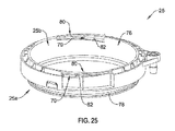
図25は、蓋リング25の斜視図である。蓋リング25は、コンテナ18の本体19(例えば上端部19b)に係合するための外部部分25a、並びに、コンテナ18の本体19の管腔19c内への中央開口部76を有する及び/又は画定する内部部分25bを含む。蓋24が蓋リング25と係合された時点で、蓋24は少なくとも部分的に中央開口部76をカバーすることができる。
FIG. 25 is a perspective view of the
蓋リング25の外部部分25aは、本体19の上端部19b内に適合するようにサイズ決定され得る。いくつかの場合、蓋リング25の外部部分25aは、Oリング(図示せず)を収容し得る刻み目78を含むことができる。Oリングが刻み目78内に位置付けされた時点で、Oリングは、蓋リング25とコンテナ18の本体19との間の密閉型シールを容易にすることができる。
The
蓋リング25の内部部分25bは、蓋24と蓋リング25との間のツイストロック連結を創出する目的で、蓋リング25の溝70内に蓋24のフランジを収容するためのフランジ開口部80を含むことができる。蓋24と蓋リング25とを係合させるためのツイストロック機構は、差し込み連結と類似であってよく、蓋リング25は、蓋24のフランジ66を収容し、蓋リング25に対して蓋を捩ることにより、蓋24は蓋リング25とさらに係合させられる。さらに、カム表面82を有する溝70及び傾斜付き表面を有するフランジ66のため、係止方向での蓋24の回転運動の後蓋リング25に対する所定の場所に蓋をツイストロックするために、摩擦嵌め連結が創出される。蓋リング25は、係止方向での蓋24のさらなる回転運動を防止するため蓋24のフランジ66又は蓋の他の部分と係合し得るリミット84を含むことができる。
The
蓋アセンブリ23の分離可能な構成(例えば蓋24と蓋リング25との間のツイストロック構成又は他の連結構成)は、コンテナ18の内部へのアクセスを提供することができる。蓋アセンブリ23の構成は、万一ドレン開口部54が詰まった状態になった場合、万一固体材料がレベルセンサ57(例えばレベルセンサ57のフロート59)と干渉した場合、及び/又は、1つ以上の他の目的のために、コンテナ18内部から材料を除去するためにコンテナ18の内部に容易にアクセスできるようにすることができる。ベース44の内部表面50は、コンテナ18内部の材料中の固体(例えば骨片、凝血塊など)をドレン開口部54に向かって及びレベルセンサ57(例えばレベルセンサ57のフロート59)から離れるように誘導し易くするように構成され得るが、固体は、コンテナ18の内部に集積し、ドレン開口部54を遮断し、及び/又は、レベルセンサ57と干渉する可能性がある。ドレン開口部54の詰まりを解消するか又はレベルセンサ57から又はレベルセンサ57に隣接する場所から材料を除去するために、コンテナアセンブリ17の蓋24を蓋リング25から除去してコンテナの内部にアクセスできるようにすることができ、ユーザーは、ドレン開口部54の動作、レベルセンサ57の動作及び/又はカート10の他の機能部の動作を改善するために、コンテナ18から材料を除去し及び/又はコンテナ18を清浄することができる。
The separable configuration of the lid assembly 23 (eg, a twist lock configuration or other coupling configuration between the
図26は、図23のライン17−17に沿って切り取られた蓋アセンブリ23の断面である。扉86は、図26中、蓋24の開口部62を閉鎖するか又は遮断している状態で示されている。扉86は、蓋24と共に形成されるか又は蓋24に連結され得る。一実施例において、図26に示されているように、扉86は、扉86が蓋24のモノリシック又は単体部分となるように、リビングヒンジ88を通して蓋24に連結されてよい。しかしながら、扉86を蓋24に連結するためには、他のヒンジ及び/又はコネクタを利用してもよい。ヒンジ88は、図26に示されているように開口部62を遮断する閉鎖位置へと扉86を付勢するように構成されてよい。
FIG. 26 is a cross-section of the
図27は、マニホルド26が蓋24の開口部62内に挿入された状態の、蓋アセンブリ23の断面図を描いている。図27に示されているように、扉86は、蓋アセンブリ23の内部に対するアクセスを提供し、蓋アセンブリがコンテナ18に連結された時点で、コンテナ18の内部に対するアクセスを提供するために、ヒンジ88を中心にして回転することができる。一実施例において、マニホルド26は、蓋24内の開口部62に挿入され得る。マニホルド26が開口部62を通って挿入されるにつれて、マニホルド26は、扉86と係合し、図27に示されている開放位置まで扉を偏向させることができる。少なくとも一部には、扉86が開口部62に向かって付勢されたリビングヒンジ88を用いて蓋24に連結されていることに起因して、使用後に又は別の目的でマニホルド26が蓋24から取り外された時点で扉86は、蓋24の中の開口部62を遮断する閉鎖位置に復帰する。
FIG. 27 depicts a cross-sectional view of the
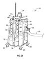
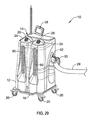
論述したように、流動性廃棄物収集カート10は、手術部位から廃棄物材料(大部分が流体、ただし一部は固体(例えば骨片、凝血塊など)を収集することができる。収集された廃棄物材料は、流動性廃棄物収集カート10のハウジング12内部のコンテナ18内に収容され得る。カート10の外部から、ユーザーは、図28に示されているように、窓90を通して材料及びコンテナ18内のこの材料のレベル92を検分することができる。いくつかの場合、例えば、流動性廃棄物収集カート10を手術室間で輸送しなければならない場合などには、コンテナ18内の材料を検分できることが望ましくない可能性がある。
As discussed, the flowable
ユーザーが処置の間にコンテナ18内の材料を容易に検分できるようにするために、と同時に材料を見ることが望ましくない場合にコンテナ18内の材料の視界を不明瞭にするか又はカバーすることを容易にするためには、窓90又はコンテナ18の本体19に対して、起動可能な(actuatable)コーティングを塗布して、コンテナ18内部の材料の視界を不明瞭にすることができる。代替的に又は付加的に、コンテナ18の内部の材料の視界を不明瞭にする目的で、窓90又はコンテナ18の本体19を製作するのに起動可能な材料を使用することができる。こうして、起動可能なコーティング又は材料が活性化された場合、コンテナ18内部の材料は、図29に示されているように、カート10の外部から検分不可能である。
To obscure or cover the view of the material in the
窓90又は本体19を不明瞭にするために使用されるコーティング又は材料は、コンテナ18内の材料に到達する又はこの材料から反射される光量を制限する(例えば暗くする、艶消しにするなど)ことができる。いくつかの事例において、窓90又は本体19を不明瞭にするために使用されるコーティング又は材料は、スイッチの活動化の時点で、電気的に活動化され起動され得る。1つの実施例において、コーティング又は材料を活動化するためのスイッチは、検分のためにコンテナ18内の材料を照明するライトを活動化させるためのライトスイッチに結び付けられていてよい。このような場合には、ライトスイッチが活動化(すなわちオン切替え)された時点で、窓90又は本体19を不明瞭化するために使用されるコーティング又は材料は非活動化されて、コンテナ18内の流体に対する可視性を可能にすることができ、ライトスイッチが非活動化(すなわちオフ切替え)された場合に、窓90又は本体19を不明瞭にするために使用されるコーティング又は材料は、活動化されてコンテナ18内の流体に対する可視性を不明瞭にすることができる。代替的に又は付加的に、コーティング又は材料の起動用のスイッチは、コントローラ100(例えば押しボタン、タッチディスプレイなど)に結び付けられていてよく、又は、カート10の他の制御機構とは別個の単独のスイッチであってよい。代替的又は付加的に、窓90をカバーしコンテナ18内部の流体の視界を選択的に遮断するために、扉を備えることができる。
The coating or material used to obscure the
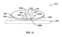
図30は、図28及び図29の医療廃棄物流体収集カート10内で使用するのに好適な着色用アセンブリ300の概略的断面図である。
FIG. 30 is a schematic cross-sectional view of a
着色用アセンブリ300は、コンテナ18の本体19と窓90との間に位置付けされ得る。描かれている実施例において、着色用アセンブリ300は、薄膜層302A及び302B、高分子分散液晶(PDLC)層304、並びに、接着剤層306を含むことができる。接着剤層306は、窓90と着色用アセンブリ300との間に位置付けされ得る。
The
コンテナ18の本体19は、一定の体積の血液を含むさまざまな生体液などの医療廃棄物を支持できる剛性構造を含むことができる。本体19は、コンテナ18の第1の側S1からコンテナ18の第2の側S2まで光が通過できるようにするため、澄んだ又は透明である材料で製造され得る。本体19の第2の側S2は、医療廃棄物を保持するように構成され得、一方、本体19の第1の側S1は、環境又は窓90に面するように構成され得る。
The
窓90は、コンテナ18の外部部分の隣に配置され得る。例えば、窓90は、コンテナ18の第1の側S1の隣に位置付けされ得る。窓90は同様に、第1の側S1から第2の側S2に光を通すことができるように、澄んだ又は透明である材料で作ることができる。さまざまな実施形態において、窓90はプラスチック又はガラス製であり得る。
着色用アセンブリ300は、窓90とコンテナ18との間に配置され得る。したがって、着色用アセンブリ300を窓90によって外部環境条件から保護し、コンテナ18によって医療廃棄物から保護することができる。しかしながら、他の実施形態においては、着色用アセンブリを窓90又はコンテナ18の中に直接組込むか、又は、コンテナ18の内側に又は窓90の外側に位置付けすることができる。描かれている実施形態において、着色用アセンブリ300は、接着剤層306を用いて窓90の内部表面に接着される。同様に、着色用アセンブリ300をコンテナ18の外部表面に取付けることも可能である。
The
描かれた実施形態において、着色用アセンブリ300は、高分子分散液晶(PDLC)層304を使用している。当該技術分野において公知であるように、PDLCは、固体ポリマーマトリクス中に分散された液晶液滴からなる。液晶液滴は、サイズがおおよそ数ミクロンであり得、電界の適用に反応する。薄膜層302A及び302Bは、マトリクスが間に分散させられた場合に、コンデンサとして作用する透明な導電層として構成され得る。コントローラ100(図3)といった電源からの電力を、薄膜層302A及び302B上の電極に取付けることができる。
In the depicted embodiment, the
電極に対していかなる電圧も印加されない場合、液晶は液滴内で無作為に配置され、その結果、第1の側S1から第2の側S2に通過するにつれての光の散乱がもたらされる。こうして、不透明又は半透明な外観を有する着色用アセンブリ300を結果として得ることができる。電極を横断して電圧が印加された場合、電界は液晶を整列させ、第1の側S1から第2の側S2に通過するにつれての散乱が極わずかである状態で光が液滴中を通過できるようにする。こうして、着色用アセンブリ300は澄んだ又は半透明の外観を有することができる。透明度レベルは、薄膜層302A及び302Bの電極を横断して印加された電圧に関係付けされ得る。電極を横断して印加される電圧は、カート10のオペレータによってコントローラ100において制御可能である。
If no voltage is applied to the electrodes, the liquid crystal is randomly placed in the droplet, resulting in light scattering as it passes from the first side S1 to the second side S2. Thus, a
着色用装置300は、医療処置の実施中又は他の状況など、コンテナ18の中味を外科医又は他の医療スタッフが検分できるようにするために、透明又は半透明状態へと活動化され得る。こうして、コンテナの容量又は医療廃棄物の状態を判定することができる。前述のように、本体19の中味が見えないように隠すか又は遮蔽するために、着色用装置300を、不透明又は半透明の状態に置くことができる。着色用装置300は、手術室の中で患者が覚醒しているか意識がある場合、カート10が公共の場所、例えば病院の廊下などにある場合、又は、他の状況において、不快な外観を有することもあり得る医療廃棄物が見られることを防ぐために、このような状態にとどまることができる。
The
PDLCに関して説明してきたが、着色用アセンブリ300は、要求に応じて、一方における透明又は半透明である状態と、他方における不透明又は半透明である状態と、の間で変換する任意の機構を含むことができる。着色用アセンブリ300は、着色用アセンブリ300の外観を清澄から不透明に変えるため、エレクトロクロミック、フォトクロミック、サーモクロミック、懸濁粒子、マイクロブラインド、及び、高分子分散液晶装置などの技術を利用することができる。
Although described with respect to PDLC,
着色用アセンブリ300は、Glass Apps、LLC又はSmart Tinc、Inc、又は、着色用アセンブリの別の商業的供給業者から市販されている着色用アセンブリを含むことができる。
The
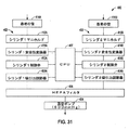
図31は、二次真空レベル検出システム402を有する流動性廃棄物収集システム400の概略的回路図である。システム400は、真空ポンプ404、フィルターエレメント406、プロセッサ407、吸引力調節器408A及び408B、制御弁410A及び410B、マニホルド412A及び412B、並びに、管414A及び414Bを含むことができる。二次真空レベル検出システム402は、安全変換器416A及び416Bを含むことができる。システム400は、二次真空レベル検出システム402が加わった状態で、図2の真空ラインシステム200と類似の要領で、構築され動作することができる。
FIG. 31 is a schematic circuit diagram of a fluid
システム400の動作中、真空ポンプ404は、管414A及び414Bにおいて真空を引き込むように動作することができる。患者からの流体は、管414A及び414B内並びにマニホルド412A及び412B内に引き込まれ得る。真空ポンプ404が吸引力を生成するにつれて、制御弁410A及び410B、吸引力調節器408A及び408B、並びに、フィルターエレメント406の中に空気が引込まれ続ける。システム400及びポンプ404を通って引き込まれた流体は、本明細書中に記載の通り、マニホルド412A及び412Bを通過しながらコンテナ18内に堆積させられる。
During operation of the
システム400のオペレータ又はユーザーは、コントローラ100内に設置され得るプロセッサ407における入力を介して、管414A及び414Bにおいて達成すべき所望の真空レベルを設定することができる。ユーザー入力は、制御弁410A及び410B並びに吸引力調節器408A及び408Bの動作状態を決定することができる。制御弁410A及び410B並びに吸引力調節器408A及び408Bは、以上で図2を参照しながら説明された弁206及び吸引力調節器214と類似の要領で動作することができる。例えば、真空ポンプ404は典型的に、システム400が活動状態にあるとき全出力で運転することができる一方で、制御弁410A及び410Bは、管414A及び414Bにおける吸引力又は真空を最大出力から低下させるために吸引力調節器408A及び408Bによって制御される。
An operator or user of
安全変換器416A及び416Bは、管414A及び414Bにおいて真空レベルを直接監視することができる。変換器416A及び416Bは、管414A及び414Bにおいて検知された真空レベルを示す信号をプロセッサ407に提供することができる。プロセッサ407は、安全変換器416A及び416Bにおいて検知された真空レベルとプロセッサ407において提供されたユーザー入力とを比較することができ、これは吸引力調節器408A及び408B並びに制御弁410A及び410Bによって制御されている。安全変換器416A及び416Bは、当該技術分野において公知である好適なセンサを含むことができる。
検知された真空レベルがユーザーの選択した真空レベルより高い場合、プロセッサ407は、修正アクションをとることができる。一実施例において、プロセッサ407は、例えばユーザー警報、例えば可聴警報又は視覚警報をディスプレイ28(図1)において生成することができる。別の実施例において、プロセッサ407は、例えば、検知された真空レベルをユーザーの選択した真空レベルに整合させる目的で制御弁410A及び410Bの開放を制限するように、吸引力調節器408A及び410Bを調整することができる。別の実施例において、プロセッサ407は、例えば真空ポンプ404の動作を停止させるか又は制御弁410A及び410Bを閉鎖することなどによって、システム400の動作をシャットダウンすることができる。
If the detected vacuum level is higher than the user selected vacuum level, the
当業者であれば、本開示が、本明細書中で説明され企図されている特定の実施形態以外のさまざまな形態で明示され得ることを認識するであろう。したがって、形態及び詳細の逸脱は、添付の特許請求の範囲に記載されている本開示の範囲及び趣旨から逸脱することなく行なうことが可能である。 Those skilled in the art will recognize that the present disclosure may be manifested in a variety of forms other than the specific embodiments described and contemplated herein. Accordingly, departures in form and detail may be made without departing from the scope and spirit of the present disclosure as set forth in the appended claims.
様々な覚書及び例
実施例1は、コンテナと、コンテナ用の底部を形成するベースであって、少なくとも部分的にドレン開口部を画定する内部表面を有する、ベースと、コンテナの内部への選択的アクセスを提供する蓋アセンブリと、を含み得る、流動性廃棄物コンテナアセンブリにおいて、ベースの内部表面が傾斜付き経路に沿って延在する、流動性廃棄物コンテナアセンブリなどの主題を含むか又は使用することができる。
Various Memorandums and Examples Example 1 is a base that forms a container and a bottom for the container, the base having an interior surface that at least partially defines a drain opening, and selective into the interior of the container Including or using a subject such as a fluid waste container assembly, wherein the inner surface of the base extends along a sloped path. be able to.
実施例2は、コンテナ内に吸引力を生成するための真空ポンプと、真空ポンプの動作を調節するための吸引力調節器と、真空ポンプにより生成された真空レベルを検知するための真空レベル検出システムと、を含むことができるか又はこれを任意に含むように実施例1の主題と任意に組合わされることができる。 The second embodiment includes a vacuum pump for generating a suction force in a container, a suction force adjuster for adjusting the operation of the vacuum pump, and a vacuum level detection for detecting a vacuum level generated by the vacuum pump. Or can optionally be combined with the subject matter of Example 1 to include it.
実施例3は、コンテナ内に少なくとも部分的に位置設定された液面センサを含むことができるか又はこれを任意に含むように実施例1又は2の1つ又はいずれかの組合せの主題と任意に組合わされることができ、液面センサは、コンテナ内の流体量に関連した測度を検知する。 Example 3 can include a liquid level sensor positioned at least partially within the container, or can optionally include one or any combination of examples 1 or 2 and subject matter The liquid level sensor senses a measure related to the amount of fluid in the container.
実施例4は、液面センサに隣接する位置からドレン開口部に隣接する位置まで螺旋経路に沿って延在することのできる内部表面を含むことができるか又はこれを任意に含むように実施例1〜3の1つ又はいずれかの組み合わせの主題と任意に組合わされることができる。 Example 4 can include or optionally include an internal surface that can extend along a helical path from a position adjacent to the liquid level sensor to a position adjacent to the drain opening. Any combination of one to three or any combination of themes can be used.
実施例5は、中央位置に噴霧開口部を含むことのできるベースを含むことができるか又はこれを任意に含むように実施例1〜4の1つ又はいずれかの組み合わせの主題と任意に組合わされることができ、内部表面は噴霧開口部からの、ドレン開口部に向い下り勾配になる傾斜付き経路に沿って延在している。 Example 5 can include a base that can include a spray opening at a central location, or can optionally be combined with the subject matter of one or any combination of Examples 1-4. The inner surfaces extend along a sloped path from the spray opening that slopes down toward the drain opening.
実施例6は、円筒形本体を有することのできるコンテナを含むことができるか又はこれを任意に含むように実施例1〜5の1つ又はいずれかの組み合わせの主題と任意に組合わされることができ、ベースは円筒形本体と係合する。 Example 6 can include a container that can have a cylindrical body or can optionally be combined with the subject matter of one or any combination of Examples 1-5 to include this. And the base engages the cylindrical body.
実施例7は、窓と、窓を選択的に着色するように構成された着色用アセンブリと、をさらに含むことのできるコンテナを含むことができるか又はこれを任意に含むように実施例1〜6の1つ又はいずれかの組み合わせの主題と任意に組合わされることができる。 Example 7 can include or optionally include a container that can further include a window and a coloring assembly configured to selectively color the window. It can be arbitrarily combined with one or any combination of the six.
実施例8は、係止用機能部を有する蓋を含むことのできる蓋アセンブリを含むことができるか又はこれを任意に含むように実施例1〜7の1つ又はいずれかの組み合わせの主題と任意に組合わされることができる。 Example 8 can include a lid assembly that can include a lid having a locking feature, or can optionally include one or any combination of Examples 1-7, and Can be arbitrarily combined.
実施例9は、蓋の回転に応じてコンテナから蓋を係合解除することのできる係止用機能部を含むことができるか又はこれを任意に含むように実施例1〜8の1つ又はいずれかの組み合わせの主題と任意に組合わされることができる。 Example 9 can include a locking feature that can disengage the lid from the container in response to rotation of the lid, or can optionally include one of Examples 1-8 or It can be arbitrarily combined with any combination of themes.
実施例10は、第1及び第2の端部を有することのできるコンテナと、コンテナの第1の端部を取り囲むベースと、蓋アセンブリであって、中央開口部を有しコンテナの第2の端部と係合する蓋リングと、ツイストロック機構を介して蓋リングと係合するように構成され蓋リングと係合したときに中央開口部の少なくとも一部分をカバーするように構成されている蓋と、を含み得る、蓋アセンブリと、を含むことのできる医療廃棄物流体収集コンテナアセンブリなどの主題を含むか又は使用することができる。 Example 10 is a container that can have first and second ends, a base that surrounds the first end of the container, a lid assembly, having a central opening and a second container A lid ring engaged with the end, and a lid configured to engage with the lid ring via a twist lock mechanism and configured to cover at least a portion of the central opening when engaged with the lid ring A lid assembly, and a subject such as a medical waste fluid collection container assembly that can include or be used.
実施例11は、蓋上のフランジと蓋リング内の溝とを含み得るツイストロック機構を含むことができるか又はこれを任意に含むように実施例10の主題と任意に組合わされることができる。 Example 11 can include a twist lock mechanism that can include a flange on the lid and a groove in the lid ring, or can optionally be combined with the subject of Example 10 to include it. .
実施例12は、係止方向への蓋の回転運動に応じて蓋リングに蓋を係止するためのカム表面を含み得る溝を含むことができるか又はこれを任意に含むように実施例10又は11の1つ又はいずれかの組み合わせの主題と任意に組合わされることができる。 Example 12 may include or optionally include a groove that may include a cam surface for locking the lid to the lid ring in response to rotational movement of the lid in the locking direction. Or any combination of 11 or any combination of themes.
実施例13は、係止方向への蓋のさらなる回転運動を防止するために蓋リングと係合するストッパ機構を含み得る蓋上のフランジを含むことができるか又はこれを任意に含むように実施例10〜12の1つ又はいずれかの組み合わせの主題と任意に組合わされることができる。 Example 13 can include or optionally include a flange on the lid that can include a stopper mechanism that engages the lid ring to prevent further rotational movement of the lid in the locking direction. It can be arbitrarily combined with one or any combination of the subjects of Examples 10-12.
実施例14は、係止方向への蓋のさらなる回転運動を防止するためにフランジと係合するリミットを含み得る蓋リングを含むことができるか又はこれを任意に含むように実施例10〜13の1つ又はいずれかの組み合わせの主題と任意に組合わされることができる。 Example 14 can include or optionally include a lid ring that can include a limit that engages the flange to prevent further rotational movement of the lid in the locking direction. Can be arbitrarily combined with one or any combination of themes.
実施例15は、蓋を通したコンテナへのアクセスを提供する扉を含み得る蓋アセンブリを含むことができるか又はこれを任意に含むように実施例10〜14の1つ又はいずれかの組み合わせの主題と任意に組合わされることができる。 Example 15 can include a lid assembly that can include a door that provides access to the container through the lid, or can optionally include one or any combination of Examples 10-14. Can be arbitrarily combined with the subject.
実施例16は、扉を蓋に連結しているリビングヒンジを含むことができるか又はこれを任意に含むように実施例10〜15の1つ又はいずれかの組み合わせの主題と任意に組合わされることができる。 Example 16 can include a living hinge that connects the door to the lid, or is optionally combined with the subject matter of one or any combination of Examples 10-15 to include this. be able to.
実施例17は、ドレン開口部と、ドレン開口部に向けて下り勾配になっている内部表面と、を含み得るコンテナのベースを含むことができるか又はこれを任意に含むように実施例10〜16の1つ又はいずれかの組み合わせの主題と任意に組合わされることができ。 Example 17 can include or optionally include a base of a container that can include a drain opening and an interior surface that is sloped down toward the drain opening. Can be arbitrarily combined with one or any combination of 16 themes.
実施例18は、窓と、窓を選択的に着色するように構成された着色用アセンブリと、を含み得るコンテナを含むことができるか又はこれを任意に含むように実施例10〜17の1つ又はいずれかの組み合わせの主題と任意に組合わされることができる。 Example 18 can include a container that can include, or optionally include, a window and a coloring assembly configured to selectively color the window. It can be arbitrarily combined with one or any combination of themes.
実施例19は、ベースを伴うコンテナを含む流体収集カートであって、ベースがコンテナの底部端部を取り囲み、ベースがドレン開口部を有する、流体収集カートと、蓋アセンブリであって、コンテナ及び流体収集カートの1つ以上と係合する蓋リングと、蓋リングに対する蓋の回転を介して蓋リングと取外し可能に係合するように構成された蓋と、を含み得る、蓋アセンブリと、コンテナであって、本体と、本体内の窓と、窓を選択的に着色するように構成された着色用アセンブリと、を含み得る、コンテナと、を含むことのできる医療廃棄物液体収集システムなどの主題を含む又はそれを使用することができる。 Example 19 is a fluid collection cart including a container with a base, wherein the base surrounds the bottom end of the container and the base has a drain opening, and a lid assembly, the container and the fluid A lid assembly, which may include a lid ring that engages one or more of the collection carts, and a lid that is configured to removably engage the lid ring via rotation of the lid relative to the lid ring; A subject such as a medical waste liquid collection system that can include a main body, a window in the main body, and a coloring assembly configured to selectively color the window. Or can be used.
実施例20は、蓋リングに対する蓋の回転に応じて蓋リングに蓋を係止するように構成されたカム表面を有し得る、蓋リング及び蓋の1つ以上を含むことができるか又はこれを任意に含むように実施例19の主題と任意に組合わされることできる。 Example 20 can include or include one or more of a lid ring and a lid that can have a cam surface configured to lock the lid to the lid ring in response to rotation of the lid relative to the lid ring. Can be optionally combined with the subject matter of Example 19.
実施例21は、コンテナと、コンテナ用の底部を形成するベースであって、少なくとも部分的にドレン開口部を画定する内部表面を有するベースと、コンテナの内部への選択的アクセスを提供する蓋アセンブリと、コンテナ内に吸引力を生成するための真空ポンプと、真空ポンプの動作を調節するための吸引力調節器と、真空ポンプにより生成された真空レベルを検知するための真空レベル検出システムと、を含み得る流動性廃棄物コンテナアセンブリなどの主題を含むか又は使用することができる。 Example 21 is a base that forms a container and a bottom for the container, the base having an interior surface that at least partially defines a drain opening, and a lid assembly that provides selective access to the interior of the container A vacuum pump for generating a suction force in the container, a suction force adjuster for adjusting the operation of the vacuum pump, a vacuum level detection system for detecting the vacuum level generated by the vacuum pump, A subject such as a fluid waste container assembly may be included or used.
これらの非限定的な実施例の各々は自立したものであり得るか、又は、他の実施例の1つ以上とさまざまな置換又は組み合わせの形で組み合わせることができる。 Each of these non-limiting examples can be self-supporting or can be combined with one or more of the other examples in various substitutions or combinations.
以上の詳細な説明には、この詳細な説明の一部を成す添付図面の参照が含まれる。図面は、一例として、本発明を実践できる具体的実施形態を示している。これらの実施形態は、本明細書中で「実施例」とも呼ばれている。このような実施例は、図示又は説明されたものに加えて複数の要素を含むことができる。しかしながら、本発明者は、同様に、図示又は説明された要素のみが提供されている実施例も企図している。その上、本発明者は、同様に、特定の実施例(又はその1つ以上の態様)に関してか又は本明細書中に図示又は説明されている他の実施例(又はその1つ以上の態様)に関して、図示又は説明されている要素(又はその1つ以上の態様)のいずれかの組合せ又は置換を使用する実施例も企図している。 The foregoing detailed description includes references to the accompanying drawings, which form a part of this detailed description. The drawings show, by way of example, specific embodiments in which the invention can be practiced. These embodiments are also referred to herein as “Examples”. Such embodiments may include a plurality of elements in addition to those shown or described. However, the inventor also contemplates embodiments in which only the elements shown or described are provided. Moreover, the inventor is equally aware of any particular embodiment (or one or more aspects thereof) or other embodiments (or one or more aspects thereof) illustrated or described herein. ) Are also contemplated using any combination or permutation of the elements shown or described (or one or more aspects thereof).
本明細書と参照により本明細書に組込まれているいずれかの文書との間で使用上の不一致が生じた場合には、本明細書中の使用法が支配する。 In the event of a usage conflict between this specification and any document incorporated herein by reference, the usage herein shall control.
本明細書中、「a」又は「an」は、特許文書中で一般的であるように、他の何らかの事例又は「少なくとも1つ」又は「1つ以上」の使用とは無関係に、1つ又は2つ以上を含むものとして使用される。本明細書において、「or(又は)」なる用語は、別段の指示の無いかぎり非排他的なものを意味するように、又は、「A又はB」が「BではなくA」、「AではなくB」及び「A及びB」を含むように使用される。本明細書では、「including(を含む)」及び「in which(その中で)」なる用語は、「comprising(を含む)」及び「wherein(ここで)」の平易な英語の等価物として使用される。同様に、以下の特許請求の範囲において、「including」及び「comprising」は、開放形である、すなわち、1つの請求項中でこのような用語の後に列挙されているものに加えた要素を含むシステム、装置、物品、組成物、調合物又はプロセスはなお、この特許請求の範囲の範囲内に入るものとみなされる。その上、以下の特許請求の範囲中、「第1の」、「第2の」及び「第3の」などの用語は標識としてのみ使用されており、その目的語に対する数値的要件を課すように意図されたものではない。 In this specification, "a" or "an" means one, regardless of any other case or use of "at least one" or "one or more" as is common in patent documents. Or it is used as what contains two or more. In this specification, the term “or (or)” means non-exclusive unless otherwise specified, or “A or B” means “A instead of B”, “ "B" and "A and B" are used. As used herein, the terms “including” and “in which” are used as plain English equivalents of “comprising” and “wherein”. Is done. Similarly, in the following claims, “including” and “comprising” are open, ie include elements in addition to those listed after such term in one claim. Systems, devices, articles, compositions, formulations or processes are still considered to be within the scope of this claim. Moreover, in the following claims, terms such as “first”, “second” and “third” are used only as labels and impose numerical requirements on the object. Not intended.
本明細書中で説明された方法例は、少なくとも部分的にマシン又はコンピュータで実施され得る。いくつかの例としては、上述の実施例の中で説明されている方法を行なうための電子装置を構成するように動作可能な命令を用いてエンコードされるコンピュータ可読媒体又はマシン可読媒体が含まれ得る。このような方法の実施には、コード、例えばマイクロコード、アセンブリ言語コード、高水準言語コードなどが含まれ得る。このようなコードは、さまざまな方法を行なうためのコンピュータ可読命令を含むことができる。コードは、コンピュータプログラムプロダクトの一部分を形成してよい。さらに、一実施例において、コードは、例えば実行中又は他の時点において、1つ以上の揮発性、非一時的又は不揮発性有形コンピュータ可読媒体上に有形記憶され得る。これらの有形コンピュータ可読媒体の例としては、非限定的に、ハードディスク、取外し可能な磁気ディスク(例えばコンパクトディスク及びデジタルビデオディスク)、磁気カセット、メモリーカード又はスティック、ランダムアクセスメモリ(RAM)、読取り専用メモリ(ROM)などが含まれ得る。 The example methods described herein may be implemented at least in part on a machine or computer. Some examples include computer readable media or machine readable media encoded with instructions operable to configure an electronic device for performing the methods described in the embodiments above. obtain. Implementation of such a method may include code, such as microcode, assembly language code, high level language code, and the like. Such code can include computer readable instructions for performing various methods. The code may form part of a computer program product. Further, in one embodiment, the code can be tangibly stored on one or more volatile, non-transitory or non-volatile tangible computer readable media, for example during execution or at other times. Examples of these tangible computer readable media include, but are not limited to, hard disks, removable magnetic disks (eg, compact disks and digital video disks), magnetic cassettes, memory cards or sticks, random access memory (RAM), read-only. A memory (ROM) or the like may be included.
以上の説明は、限定的ではなく例示的であるように意図されている。例えば、上述の実施例(又はその1つ以上の態様)は、互いに組合せた形で使用可能である。以上の説明を精査した上で当業者によってなど、他の実施形態の使用も可能である。要約書は、技術的開示の内容を読者が迅速に確定できるようにするため、37C.F.R.§1.72(b)を遵守する目的で提供されている。これは、特許請求の範囲の範囲又は意味を解釈又は限定するために使用されるものでないことを理解した上で提出されるものである。同様に、上述の詳細な説明において、開示を簡素化するためにさまざまな特徴がまとめられている場合がある。これは、請求されていない開示された特徴がどの請求項にとっても必須であることを意図しているものと解決されるべきではない。むしろ、発明力ある主題は、特定の開示された実施形態の全ての特徴よりも少ない特徴の中に存在し得る。したがって、以下の特許請求の範囲は、本明細書によって、各請求項が別個の実施形態として自立している状態で、実施例又は実施形態として詳細な説明の中で組込まれ、このような実施形態はさまざまな組合せ又は置換の形で互いに組み合わせることができるということが企図されている。本発明の範囲は、添付の特許請求の範囲が権限を有する全範囲の等価物と共に、添付の特許請求の範囲を参照して決定されるべきである。 The above description is intended to be illustrative rather than limiting. For example, the above-described embodiments (or one or more aspects thereof) can be used in combination with each other. Other embodiments may be used, such as by one skilled in the art after reviewing the above description. The abstract should be 37C.D so that the reader can quickly determine the content of the technical disclosure. F. R. Provided to comply with § 1.72 (b). It is submitted with the understanding that it will not be used to interpret or limit the scope or meaning of the claims. Similarly, in the foregoing detailed description, various features may be grouped together to simplify the disclosure. This should not be construed as intending that an unclaimed disclosed feature is essential to any claim. Rather, inventive subject matter may lie in less than all features of a particular disclosed embodiment. Thus, the following claims are hereby incorporated into this Detailed Description as examples or embodiments, with each claim standing on its own as a separate embodiment. It is contemplated that the forms can be combined with each other in various combinations or substitutions. The scope of the invention should be determined with reference to the appended claims, along with the full scope of equivalents to which such claims are entitled.
Claims (21)
前記コンテナ用の底部を形成するベースであって、少なくとも部分的にドレン開口部を画定する内部表面を有する、ベースと、
前記コンテナの内部への選択的アクセスを提供する蓋アセンブリと、
を備える、流動性廃棄物コンテナアセンブリにおいて、
前記ベースの前記内部表面が傾斜付き経路に沿って延在する、流動性廃棄物コンテナアセンブリ。 A container,
A base forming a bottom for the container, the base having an internal surface at least partially defining a drain opening;
A lid assembly that provides selective access to the interior of the container;
In a fluid waste container assembly comprising:
A flowable waste container assembly, wherein the inner surface of the base extends along a sloped path.
前記真空ポンプの動作を調節するための吸引力調節器と、
前記真空ポンプにより生成された真空レベルを検知するための真空レベル検出システムと、
をさらに備える、請求項1に記載の流動性廃棄物コンテナアセンブリ。 A vacuum pump for generating a suction force in the container;
A suction force adjuster for adjusting the operation of the vacuum pump;
A vacuum level detection system for detecting the vacuum level generated by the vacuum pump;
The flowable waste container assembly of claim 1, further comprising:
前記液面センサが、前記コンテナ内の流体量に関連した測度を検知する、請求項1又は2に記載の流動性廃棄物コンテナアセンブリ。 A liquid level sensor positioned at least partially within the container;
3. A fluid waste container assembly according to claim 1 or 2, wherein the liquid level sensor senses a measure related to the amount of fluid in the container.
窓と、
前記窓を選択的に着色するように構成された着色用アセンブリと、
を含む、請求項1〜6のいずれか1項に記載の流動性廃棄物コンテナアセンブリ。 The container
Windows,
A coloring assembly configured to selectively color the window;
7. A flowable waste container assembly according to any one of claims 1-6.
前記コンテナの前記第1の端部を取り囲むベースと、
蓋アセンブリであって
中央開口部を有し、前記コンテナの前記第2の端部と係合する蓋リングと
ツイストロック機構を介して前記蓋リングと係合するように構成され、前記蓋リングと係合したときに前記中央開口部の少なくとも一部分をカバーするように構成されている蓋と、
を含む、蓋アセンブリと、
を備える、医療廃棄物流体収集コンテナアセンブリ。 A container having first and second ends;
A base surrounding the first end of the container;
A lid assembly having a central opening and configured to engage the lid ring via a twist lock mechanism; and a lid ring that engages the second end of the container; A lid configured to cover at least a portion of the central opening when engaged;
Including a lid assembly;
A medical waste fluid collection container assembly comprising:
ドレン開口部と、
前記ドレン開口部に向けて下り勾配になっている内部表面と、
を含む、請求項10〜16のいずれか1項に記載のコンテナアセンブリ。 The base of the container is
A drain opening;
An internal surface that is descending toward the drain opening;
The container assembly according to claim 10, comprising:
窓と、
前記窓を選択的に着色するように構成された着色用アセンブリと、
を含む、請求項10〜17のいずれか1項に記載の流動性廃棄物コンテナアセンブリ。 The container
Windows,
A coloring assembly configured to selectively color the window;
18. A flowable waste container assembly according to any one of claims 10 to 17, comprising:
蓋アセンブリであって、
前記コンテナ及び前記流体収集カートの1つ以上と係合する蓋リングと、
蓋であって、前記蓋リングに対する当該蓋の回転を介して前記蓋リングと取外し可能に係合するように構成された、蓋と、
を含む、蓋アセンブリと、
コンテナであって、
本体と、
前記本体内の窓と、
前記窓を選択的に着色するように構成された着色用アセンブリと、
を含む、コンテナと、
を備える、医療廃棄物流体収集システム。 A fluid collection cart including a container with a base, wherein the base surrounds a bottom end of the container, and the base has a drain opening;
A lid assembly,
A lid ring engaging one or more of the container and the fluid collection cart;
A lid, wherein the lid is configured to removably engage with the lid ring through rotation of the lid relative to the lid ring;
Including a lid assembly;
A container,
The body,
A window in the body;
A coloring assembly configured to selectively color the window;
Including a container, and
A medical waste fluid collection system comprising:
前記コンテナ用の底部を形成するベースであって、少なくとも部分的にドレン開口部を画定する内部表面を有する、ベースと、
前記コンテナの内部への選択的アクセスを提供する蓋アセンブリと、
前記コンテナ内に吸引力を生成するための真空ポンプと、
前記真空ポンプの動作を調節するための吸引力調節器と、
前記真空ポンプにより生成された真空レベルを検知するための真空レベル検出システムと、
を備える、流動性廃棄物コンテナアセンブリ。 A container,
A base forming a bottom for the container, the base having an internal surface at least partially defining a drain opening;
A lid assembly that provides selective access to the interior of the container;
A vacuum pump for generating a suction force in the container;
A suction force adjuster for adjusting the operation of the vacuum pump;
A vacuum level detection system for detecting the vacuum level generated by the vacuum pump;
A fluid waste container assembly comprising:
Applications Claiming Priority (3)
| Application Number | Priority Date | Filing Date | Title |
|---|---|---|---|
| US201562199539P | 2015-07-31 | 2015-07-31 | |
| US62/199,539 | 2015-07-31 | ||
| PCT/US2016/044657 WO2017023732A1 (en) | 2015-07-31 | 2016-07-29 | Medical waste fluid collection and disposal system |
Publications (2)
| Publication Number | Publication Date |
|---|---|
| JP2018528043A true JP2018528043A (en) | 2018-09-27 |
| JP7210281B2 JP7210281B2 (en) | 2023-01-23 |
Family
ID=56610017
Family Applications (1)
| Application Number | Title | Priority Date | Filing Date |
|---|---|---|---|
| JP2018525523A Active JP7210281B2 (en) | 2015-07-31 | 2016-07-29 | Medical waste fluid collection and disposal system |
Country Status (7)
| Country | Link |
|---|---|
| US (3) | US10940242B2 (en) |
| EP (1) | EP3328459B1 (en) |
| JP (1) | JP7210281B2 (en) |
| AU (1) | AU2016303432B2 (en) |
| CA (1) | CA2994152C (en) |
| NZ (1) | NZ739592A (en) |
| WO (1) | WO2017023732A1 (en) |
Cited By (2)
| Publication number | Priority date | Publication date | Assignee | Title |
|---|---|---|---|---|
| US10940242B2 (en) | 2015-07-31 | 2021-03-09 | Dornoch Medical Systems, Inc. | Medical waste fluid collection and disposal system |
| JP2024129055A (en) * | 2019-04-12 | 2024-09-26 | ストライカー・コーポレイション | Waste collection cart for collecting waste during medical procedures |
Families Citing this family (19)
| Publication number | Priority date | Publication date | Assignee | Title |
|---|---|---|---|---|
| FI3542833T3 (en) | 2012-10-24 | 2023-09-26 | Stryker Corp | Garbage collection assembly |
| USD932614S1 (en) | 2018-01-05 | 2021-10-05 | Serres Oy | Suction device for medical use |
| EP3653239A1 (en) * | 2018-11-13 | 2020-05-20 | Epic Medical Pte Ltd | Infusion pump control method, infusion pump and tube cassette for fluid delivery |
| WO2020117587A2 (en) * | 2018-12-05 | 2020-06-11 | Stryker Corporation | A medical waste management system integrated within a medical facility |
| CN109771048B (en) * | 2019-01-16 | 2024-08-20 | 美昕医疗器械(上海)有限公司 | Consumable box |
| US12350418B2 (en) | 2019-04-12 | 2025-07-08 | Stryker Corporation | Manifold for a medical waste collection system |
| US11318242B2 (en) | 2019-04-12 | 2022-05-03 | Stryker Corporation | Manifold for a medical waste collection system |
| US10471188B1 (en) | 2019-04-12 | 2019-11-12 | Stryker Corporation | Manifold for filtering medical waste being drawn under vacuum into a medical waste collection system |
| USD919799S1 (en) | 2019-11-11 | 2021-05-18 | Stryker Corporation | Manifold housing for a medical waste collection device |
| USD956967S1 (en) | 2019-11-11 | 2022-07-05 | Stryker Corporation | Manifold housing for a medical waste collection device |
| USD996640S1 (en) | 2019-11-11 | 2023-08-22 | Stryker Corporation | Specimen collection tray |
| USD930850S1 (en) | 2019-11-20 | 2021-09-14 | Stryker Corporation | Specimen collection tray |
| USD1031076S1 (en) | 2019-11-20 | 2024-06-11 | Stryker Corporation | Specimen collection tray |
| US11628242B2 (en) | 2020-09-10 | 2023-04-18 | Fresenius Medical Care Holdings, Inc. | Spent dialysate container for disposing spent dialysate in a dialysis system |
| USD959658S1 (en) | 2020-10-12 | 2022-08-02 | Stryker Corportation | Medical waste collection unit |
| US20220330958A1 (en) * | 2021-04-19 | 2022-10-20 | Argon Medical Devices, Inc. | Disposable thrombectomy maceration and aspiration system |
| CN113648161A (en) * | 2021-08-16 | 2021-11-16 | 深圳市第二人民医院(深圳市转化医学研究院) | Waste liquid collecting device for nephrology department and using method thereof |
| CN114699324B (en) * | 2022-06-06 | 2022-08-16 | 烟台康骨堂医药科技有限公司 | Safe waste liquid collection device for medical nursing |
| GB2640267A (en) * | 2024-04-09 | 2025-10-15 | Balbir Singh Manial | Bin for liquid waste storage |
Citations (5)
| Publication number | Priority date | Publication date | Assignee | Title |
|---|---|---|---|---|
| JP2001017489A (en) * | 1999-06-28 | 2001-01-23 | American Immuno Tech Llc | Waste disposal system |
| JP2002531877A (en) * | 1998-11-30 | 2002-09-24 | ジェンテクス・コーポレーション | Electrochromic structure |
| JP2009519757A (en) * | 2005-12-14 | 2009-05-21 | ストライカー・コーポレイション | Medical / surgical waste collection and treatment system |
| JP2010540193A (en) * | 2007-10-04 | 2010-12-24 | ドアノック・メディカル・システムズ・インコーポレーテッド | Medical waste fluid collection and disposal system |
| WO2015055893A1 (en) * | 2013-10-16 | 2015-04-23 | Serres Oy | Emptying device, assembly, and method for emptying suction bag |
Family Cites Families (48)
| Publication number | Priority date | Publication date | Assignee | Title |
|---|---|---|---|---|
| FR2610906B1 (en) * | 1987-02-16 | 1989-06-30 | Light Shadow Inc | FILM REEL STORAGE BOX FOR PHOTOGRAPHER |
| US6027490A (en) * | 1996-01-24 | 2000-02-22 | Radford; Fred R. | Contaminated medical waste disposal system and method |
| US6352525B1 (en) | 1999-09-22 | 2002-03-05 | Akio Wakabayashi | Portable modular chest drainage system |
| US6270488B1 (en) * | 2000-01-24 | 2001-08-07 | Allegiance Corporation | Large volume medical fluid vacuum collection canister |
| US6780637B2 (en) * | 2002-01-25 | 2004-08-24 | Paul A. Olivier | Disposal apparatus and method for efficiently bio-converting putrescent wastes |
| US6793814B2 (en) * | 2002-10-08 | 2004-09-21 | M-I L.L.C. | Clarifying tank |
| CA2561035A1 (en) * | 2004-03-23 | 2005-10-06 | Dubois Limited | Container with securement means for a pack |
| US8137329B2 (en) * | 2004-03-25 | 2012-03-20 | Medindica-Pak, Inc. | Method and apparatus for transforming a delivery container into a waste disposal system |
| US20060163252A1 (en) * | 2005-01-24 | 2006-07-27 | Letica Corporation | Container |
| DE102005014420A1 (en) * | 2005-03-24 | 2006-09-28 | Inmeditec Medizintechnik Gmbh | Vacuum therapy device |
| US7857806B2 (en) * | 2005-07-14 | 2010-12-28 | Boehringer Technologies, L.P. | Pump system for negative pressure wound therapy |
| US7134620B1 (en) * | 2005-12-19 | 2006-11-14 | Ming-Tsung Lee | Electric ice planer |
| JP4238257B2 (en) * | 2006-06-28 | 2009-03-18 | 株式会社日立製作所 | Automatic urine collecting device |
| US8500706B2 (en) * | 2007-03-23 | 2013-08-06 | Allegiance Corporation | Fluid collection and disposal system having interchangeable collection and other features and methods relating thereto |
| GB0708626D0 (en) * | 2007-05-04 | 2007-06-13 | Meadwestvaco Corp | Closure for a container |
| US8508695B2 (en) * | 2007-06-25 | 2013-08-13 | Vlyte Innovations, Ltd | Polymer-dispersed liquid crystal structures with substituent functional group to alignment within liquid crystal material body into polydomain state |
| US9408954B2 (en) * | 2007-07-02 | 2016-08-09 | Smith & Nephew Plc | Systems and methods for controlling operation of negative pressure wound therapy apparatus |
| US20090015740A1 (en) * | 2007-07-12 | 2009-01-15 | Ravil Sagitov | Window darkening system |
| US20100052293A1 (en) * | 2008-08-29 | 2010-03-04 | Brooks Vincent L | Mobile modular cart/case system for oxygen concentrators and infusion pump systems |
| US8212949B2 (en) * | 2008-09-15 | 2012-07-03 | Gojo Industries, Inc. | System for selectively revealing indicia |
| US9514662B2 (en) * | 2008-09-15 | 2016-12-06 | Gojo Industries, Inc. | System for selectively revealing indicia |
| GB0817296D0 (en) * | 2008-09-22 | 2008-10-29 | Pilkington Group Ltd | Methods of switching and apparatus comprising an electrically actuated variable transmission material |
| JP5356838B2 (en) * | 2009-01-20 | 2013-12-04 | 株式会社日立製作所 | Automatic urine collecting device |
| JP2010211177A (en) * | 2009-02-12 | 2010-09-24 | Kenichi Kawagoe | Liquid crystal shutter glasses |
| US8172832B1 (en) * | 2009-04-07 | 2012-05-08 | Ruben Gonzalez | Fat harvesting container |
| US8366694B1 (en) * | 2009-05-22 | 2013-02-05 | Donnell Mark Jordan | Tissue refining device |
| US8678222B2 (en) * | 2010-04-30 | 2014-03-25 | Hct Asia Ltd | Airtight compact |
| WO2012082715A2 (en) * | 2010-12-13 | 2012-06-21 | Case Western Reserve University | Device with external pressure sensors for enhancing patient care and methods of using same |
| MX2011002176A (en) * | 2011-02-25 | 2012-08-30 | Tricorbraun S De R L De C V | ¼ turn closing system for a container. |
| US9341912B2 (en) * | 2012-03-13 | 2016-05-17 | View, Inc. | Multi-zone EC windows |
| US8985371B2 (en) * | 2012-08-10 | 2015-03-24 | Daniel A. Zabaleta | Resealable beverage containers and methods of making same |
| KR102121527B1 (en) * | 2012-08-30 | 2020-06-10 | 삼성전자주식회사 | Method and device for adjusting transparency of display being used for packaging product |
| FI3542833T3 (en) * | 2012-10-24 | 2023-09-26 | Stryker Corp | Garbage collection assembly |
| US8830076B2 (en) * | 2012-11-21 | 2014-09-09 | Owens-Brockway Glass Container Inc. | Container having a use-evident device |
| DE102013005743B4 (en) * | 2013-04-05 | 2021-03-18 | Fresenius Medical Care Deutschland Gmbh | Device and method for supporting the operation of medical technical devices |
| KR20140124283A (en) * | 2013-04-16 | 2014-10-24 | 삼성디스플레이 주식회사 | Nusing bottle using transparent flexible display |
| KR101728196B1 (en) * | 2013-04-26 | 2017-04-18 | 엘지전자 주식회사 | Refrigerator |
| US9417471B2 (en) * | 2013-04-30 | 2016-08-16 | Research Frontiers Incorporated | Method and device for protecting objects from degradation by light with suspended particle device light valves |
| DE102013208107A1 (en) * | 2013-05-03 | 2014-11-06 | Paul Hartmann Ag | Fluid receptacle for a device for providing negative pressure for medical applications, and device |
| US10031356B2 (en) * | 2013-07-11 | 2018-07-24 | Merck Patent Gmbh | Fail safe mechanism for switchable window |
| WO2015016154A1 (en) * | 2013-07-29 | 2015-02-05 | 九州ナノテック光学株式会社 | Opening/closing tool |
| GB2525836B (en) * | 2013-11-25 | 2017-09-20 | Kenwood Ltd | Electro chromatic vessels for processing and storage for foodstuffs |
| US9345820B2 (en) * | 2014-01-08 | 2016-05-24 | Jacqueline D. Nobles | Suction canister cover |
| EP3659638B1 (en) * | 2014-07-31 | 2026-01-07 | Smith & Nephew, Inc. | Systems and methods for applying reduced pressure therapy |
| US9612207B2 (en) * | 2015-07-09 | 2017-04-04 | Lam Research Corporation | Smart window for semiconductor processing tool |
| US20170017100A1 (en) * | 2015-07-17 | 2017-01-19 | Iris Optronics Inc. | Smart curtain film |
| WO2017023732A1 (en) | 2015-07-31 | 2017-02-09 | Dornoch Medical Systems, Inc. | Medical waste fluid collection and disposal system |
| US10835650B2 (en) | 2015-10-09 | 2020-11-17 | Arc Medical Design Limited | Device for collection of tissue and method of use |
-
2016
- 2016-07-29 WO PCT/US2016/044657 patent/WO2017023732A1/en not_active Ceased
- 2016-07-29 NZ NZ739592A patent/NZ739592A/en not_active IP Right Cessation
- 2016-07-29 JP JP2018525523A patent/JP7210281B2/en active Active
- 2016-07-29 US US15/223,254 patent/US10940242B2/en active Active
- 2016-07-29 EP EP16748017.7A patent/EP3328459B1/en active Active
- 2016-07-29 CA CA2994152A patent/CA2994152C/en active Active
- 2016-07-29 AU AU2016303432A patent/AU2016303432B2/en active Active
-
2021
- 2021-02-02 US US17/165,206 patent/US11969537B2/en active Active
-
2024
- 2024-03-18 US US18/608,164 patent/US20240216601A1/en active Pending
Patent Citations (5)
| Publication number | Priority date | Publication date | Assignee | Title |
|---|---|---|---|---|
| JP2002531877A (en) * | 1998-11-30 | 2002-09-24 | ジェンテクス・コーポレーション | Electrochromic structure |
| JP2001017489A (en) * | 1999-06-28 | 2001-01-23 | American Immuno Tech Llc | Waste disposal system |
| JP2009519757A (en) * | 2005-12-14 | 2009-05-21 | ストライカー・コーポレイション | Medical / surgical waste collection and treatment system |
| JP2010540193A (en) * | 2007-10-04 | 2010-12-24 | ドアノック・メディカル・システムズ・インコーポレーテッド | Medical waste fluid collection and disposal system |
| WO2015055893A1 (en) * | 2013-10-16 | 2015-04-23 | Serres Oy | Emptying device, assembly, and method for emptying suction bag |
Cited By (4)
| Publication number | Priority date | Publication date | Assignee | Title |
|---|---|---|---|---|
| US10940242B2 (en) | 2015-07-31 | 2021-03-09 | Dornoch Medical Systems, Inc. | Medical waste fluid collection and disposal system |
| US11969537B2 (en) | 2015-07-31 | 2024-04-30 | Dornoch Medical Systems, Inc. | Medical waste fluid collection and disposal system |
| JP2024129055A (en) * | 2019-04-12 | 2024-09-26 | ストライカー・コーポレイション | Waste collection cart for collecting waste during medical procedures |
| JP7839224B2 (en) | 2019-04-12 | 2026-04-01 | ストライカー・コーポレイション | Waste collection cart for collecting waste during medical procedures |
Also Published As
| Publication number | Publication date |
|---|---|
| WO2017023732A1 (en) | 2017-02-09 |
| CA2994152A1 (en) | 2017-02-09 |
| EP3328459A1 (en) | 2018-06-06 |
| US11969537B2 (en) | 2024-04-30 |
| NZ739592A (en) | 2020-07-31 |
| CA2994152C (en) | 2021-08-10 |
| AU2016303432B2 (en) | 2020-02-27 |
| US20210154375A1 (en) | 2021-05-27 |
| US20240216601A1 (en) | 2024-07-04 |
| EP3328459B1 (en) | 2020-05-06 |
| AU2016303432A1 (en) | 2018-02-22 |
| JP7210281B2 (en) | 2023-01-23 |
| US20170028110A1 (en) | 2017-02-02 |
| US10940242B2 (en) | 2021-03-09 |
Similar Documents
| Publication | Publication Date | Title |
|---|---|---|
| JP7210281B2 (en) | Medical waste fluid collection and disposal system | |
| US11241525B2 (en) | Wound exudate monitor accessory | |
| US11116884B2 (en) | Integrated system for assessing wound exudates | |
| US20160331876A1 (en) | Fluid collection and disposal system | |
| EP2190497B1 (en) | Automated body fluid drain control apparatus | |
| JP6634661B2 (en) | Systems, instruments and methods for draining and analyzing body fluids | |
| US20190307931A1 (en) | A method, arrangement and a user interface for controlling collecting fluid from a patient | |
| US20260108668A1 (en) | Devices and methods for managing chest or wound drainage | |
| KR20250084740A (en) | Device for processing pharmaceutical waste |
Legal Events
| Date | Code | Title | Description |
|---|---|---|---|
| A621 | Written request for application examination |
Free format text: JAPANESE INTERMEDIATE CODE: A621 Effective date: 20190719 |
|
| A977 | Report on retrieval |
Free format text: JAPANESE INTERMEDIATE CODE: A971007 Effective date: 20200605 |
|
| A131 | Notification of reasons for refusal |
Free format text: JAPANESE INTERMEDIATE CODE: A131 Effective date: 20200623 |
|
| A521 | Request for written amendment filed |
Free format text: JAPANESE INTERMEDIATE CODE: A523 Effective date: 20200904 |
|
| A131 | Notification of reasons for refusal |
Free format text: JAPANESE INTERMEDIATE CODE: A131 Effective date: 20210302 |
|
| A521 | Request for written amendment filed |
Free format text: JAPANESE INTERMEDIATE CODE: A523 Effective date: 20210526 |
|
| A02 | Decision of refusal |
Free format text: JAPANESE INTERMEDIATE CODE: A02 Effective date: 20211102 |
|
| C60 | Trial request (containing other claim documents, opposition documents) |
Free format text: JAPANESE INTERMEDIATE CODE: C60 Effective date: 20220125 |
|
| A521 | Request for written amendment filed |
Free format text: JAPANESE INTERMEDIATE CODE: A821 Effective date: 20220128 |
|
| C22 | Notice of designation (change) of administrative judge |
Free format text: JAPANESE INTERMEDIATE CODE: C22 Effective date: 20220712 |
|
| C22 | Notice of designation (change) of administrative judge |
Free format text: JAPANESE INTERMEDIATE CODE: C22 Effective date: 20220719 |
|
| C13 | Notice of reasons for refusal |
Free format text: JAPANESE INTERMEDIATE CODE: C13 Effective date: 20220823 |
|
| A521 | Request for written amendment filed |
Free format text: JAPANESE INTERMEDIATE CODE: A523 Effective date: 20220913 |
|
| C23 | Notice of termination of proceedings |
Free format text: JAPANESE INTERMEDIATE CODE: C23 Effective date: 20221115 |
|
| C03 | Trial/appeal decision taken |
Free format text: JAPANESE INTERMEDIATE CODE: C03 Effective date: 20221213 |
|
| C30A | Notification sent |
Free format text: JAPANESE INTERMEDIATE CODE: C3012 Effective date: 20221213 |
|
| A61 | First payment of annual fees (during grant procedure) |
Free format text: JAPANESE INTERMEDIATE CODE: A61 Effective date: 20230111 |
|
| R150 | Certificate of patent or registration of utility model |
Ref document number: 7210281 Country of ref document: JP Free format text: JAPANESE INTERMEDIATE CODE: R150 |
|
| R250 | Receipt of annual fees |
Free format text: JAPANESE INTERMEDIATE CODE: R250 |