JP2019012002A - Current detecting device and measuring device - Google Patents
Current detecting device and measuring device Download PDFInfo
- Publication number
- JP2019012002A JP2019012002A JP2017128221A JP2017128221A JP2019012002A JP 2019012002 A JP2019012002 A JP 2019012002A JP 2017128221 A JP2017128221 A JP 2017128221A JP 2017128221 A JP2017128221 A JP 2017128221A JP 2019012002 A JP2019012002 A JP 2019012002A
- Authority
- JP
- Japan
- Prior art keywords
- current
- detection
- magnetic core
- feedback winding
- resistor
- Prior art date
- Legal status (The legal status is an assumption and is not a legal conclusion. Google has not performed a legal analysis and makes no representation as to the accuracy of the status listed.)
- Pending
Links
Images


Classifications
-
- G—PHYSICS
- G01—MEASURING; TESTING
- G01R—MEASURING ELECTRIC VARIABLES; MEASURING MAGNETIC VARIABLES
- G01R15/00—Details of measuring arrangements of the types provided for in groups G01R17/00 - G01R29/00, G01R33/00 - G01R33/26 or G01R35/00
- G01R15/14—Adaptations providing voltage or current isolation, e.g. for high-voltage or high-current networks
- G01R15/18—Adaptations providing voltage or current isolation, e.g. for high-voltage or high-current networks using inductive devices, e.g. transformers
- G01R15/183—Adaptations providing voltage or current isolation, e.g. for high-voltage or high-current networks using inductive devices, e.g. transformers using transformers with a magnetic core
- G01R15/185—Adaptations providing voltage or current isolation, e.g. for high-voltage or high-current networks using inductive devices, e.g. transformers using transformers with a magnetic core with compensation or feedback windings or interacting coils, e.g. 0-flux sensors
-
- G—PHYSICS
- G01—MEASURING; TESTING
- G01R—MEASURING ELECTRIC VARIABLES; MEASURING MAGNETIC VARIABLES
- G01R15/00—Details of measuring arrangements of the types provided for in groups G01R17/00 - G01R29/00, G01R33/00 - G01R33/26 or G01R35/00
- G01R15/14—Adaptations providing voltage or current isolation, e.g. for high-voltage or high-current networks
- G01R15/20—Adaptations providing voltage or current isolation, e.g. for high-voltage or high-current networks using galvano-magnetic devices, e.g. Hall-effect devices, i.e. measuring a magnetic field via the interaction between a current and a magnetic field, e.g. magneto resistive or Hall effect devices
Landscapes
- Engineering & Computer Science (AREA)
- Power Engineering (AREA)
- Physics & Mathematics (AREA)
- General Physics & Mathematics (AREA)
- Measuring Instrument Details And Bridges, And Automatic Balancing Devices (AREA)
Abstract
【課題】ゼロフラックス方式動作とCT動作とを組み合わせつつ、ゼロフラックス方式動作時のS/N比の低下を回避し、かつCT動作時の帰還巻線での共振を防止する。【解決手段】磁気コア2に組み込まれて測定対象電線64に流れる電流Iの電流値I1を示す検出信号S3を出力する磁気センサ3と、磁気コア2に巻回された帰還巻線4と、検出信号S3の振幅を低下させるように駆動電流Idを帰還巻線4に供給する駆動部6と、駆動電流Idの電流路内に配設されて駆動電流Idを電圧Vdに変換して出力する検出抵抗7とを備えている。帰還巻線4は、磁気コア2の周方向に沿って配置された複数の巻線4a,4bが直列に接続されて構成され、各巻線4a,4bには、第1抵抗およびコンデンサの直列回路を含んで構成される共振防止回路9が並列に接続されている。【選択図】図1A zero flux method operation and a CT operation are combined, a decrease in the S / N ratio during the zero flux method operation is avoided, and resonance in a feedback winding during the CT operation is prevented. A magnetic sensor 3 that outputs a detection signal S3 indicating a current value I1 of a current I that is incorporated in a magnetic core 2 and flows through a measurement target electric wire 64; a feedback winding 4 wound around the magnetic core 2; A drive unit 6 that supplies the drive current Id to the feedback winding 4 so as to reduce the amplitude of the detection signal S3, and a drive current Id that is disposed in the current path of the drive current Id is converted into a voltage Vd and output. And a detection resistor 7. The feedback winding 4 is configured by connecting a plurality of windings 4a and 4b arranged in the circumferential direction of the magnetic core 2 in series, and each winding 4a and 4b includes a series circuit of a first resistor and a capacitor. Are connected in parallel. [Selection] Figure 1
Description
本発明は、測定対象電線に流れる電流を、この電流が低周波領域に含まれる周波数の信号のときにはゼロフラックス法により検出し、この電流が高周波領域に含まれる周波数の信号のときには帰還巻線をCT(カレントトランス)として機能させて検出する電流検出装置、およびこの電流検出装置を備えた測定装置に関するものである。 In the present invention, the current flowing through the measurement target wire is detected by the zero flux method when the current is a frequency signal included in the low frequency region, and the feedback winding is detected when the current is a frequency signal included in the high frequency region. The present invention relates to a current detection device that functions as a CT (current transformer) for detection, and a measurement device including the current detection device.
測定対象電線に流れる電流をゼロフラックス法によって検出する電流検出装置として、本願出願人は下記特許文献1に開示された電流検出装置を既に提案している。この電流検出装置は、円環状の磁気コアと、この磁気コアに挿通された測定対象電線に流れる電流の電流値に比例して振幅が変化する検出信号を出力するフラックスゲート型磁気センサと、磁気コアの外表面に導線を巻回して構成された帰還巻線と、フラックスゲートセンサ素子に励磁信号を出力する信号生成部と、検出信号を入力すると共に検出信号の振幅を低下させる駆動電流を帰還巻線に供給する駆動部と、駆動電流の電流路内に配設されて駆動電流を電圧に変換して出力する検出抵抗とを備えて、磁気センサを使用したゼロフラックス方式の電流検出装置として構成されている。また、帰還巻線には、巻始め端および巻き終わり端のうちの一方から他方に向かう駆動電流が供給されると共に、帰還巻線は、中間層の部位において巻始め端側の第1帰還巻線と巻き終わり端側の第2帰還巻線とに分割されている。また、検出抵抗は、第1帰還巻線と第2帰還巻線との間に接続されている。
The present applicant has already proposed the current detection device disclosed in
ところで、上記の特許文献1には開示されていないが、上記の電流検出装置では、ゼロフラックス方式で動作する作動周波数帯域、つまり、駆動部が磁気センサからの検出信号を入力すると共にこの検出信号の振幅を低下させる駆動電流を帰還巻線に供給し得る周波数帯域(つまり、磁気コアに発生する磁束をゼロにし得る周波数帯域)を超える高周波領域においては、磁気センサや駆動部の利得が大幅に低下することから、駆動部から帰還巻線への出力電圧がほぼゼロボルトになる。これにより、帰還巻線の両端部(巻始め端側の端部と巻き終わり端側の端部)は実質的に同電位となって、等価的に互いに接続された状態となることから、帰還巻線は、高周波領域においてCT(カレントトランス)として機能するようになる。この構成により、上記の電流検出装置は、測定対象電線に流れる電流の周波数が低周波領域に含まれるときには、ゼロフラックス方式で動作してこの電流を検出すると共に、測定対象電線に流れる電流の周波数が高周波領域に含まれるときには、帰還巻線がCTとして動作してこの電流を検出することにより、測定対象電線に流れる電流を低周波領域から高周波領域までの広帯域に亘って検出し得るようになっている。
By the way, although not disclosed in the above-mentioned
また、この電流検出装置では、帰還巻線がCTとして動作する高周波領域において、帰還巻線の寄生容量に起因して生じる共振を防止して、周波数特性を改善するため(作動周波数帯域をより高域まで伸ばすため)に、第1帰還巻線と第2帰還巻線のそれぞれに並列に共振防止用抵抗を接続する構成を採用している。この場合、共振防止用抵抗は、抵抗値が大きすぎると共振防止の効果が発揮し得ないことから、共振防止用抵抗には、ある程度小さな抵抗値の抵抗を使用する必要がある。 Further, in this current detection device, in the high frequency region where the feedback winding operates as CT, resonance caused by the parasitic capacitance of the feedback winding is prevented and the frequency characteristics are improved (the operating frequency band is further increased). In order to extend it to the region, a configuration in which a resonance preventing resistor is connected in parallel to each of the first feedback winding and the second feedback winding is employed. In this case, if the resistance value of the resonance preventing resistor is too large, the effect of preventing resonance cannot be exerted. Therefore, it is necessary to use a resistor having a somewhat small resistance value as the resonance preventing resistor.
しかしながら、このような小さな抵抗値の抵抗を共振防止用抵抗として使用した場合には、ゼロフラックス方式で動作したときに、磁気センサに供給されている励磁信号の信号成分が帰還巻線を経由する経路ではなく、この共振防止用抵抗を経由する経路で検出抵抗に伝わる。このため、この電流検出装置には、ゼロフラックス方式で動作したときの(低周波領域での)S/N比が低下する虞があるという改善すべき課題が存在している。なお、帰還巻線がCTとして動作する高周波領域では、上記した磁気センサや駆動部と同様にして、信号生成部の利得も大幅に低下することから、励磁信号の振幅がほぼゼロになる。このため、励磁信号の信号成分の検出抵抗への影響は無視することができる。 However, when such a resistance having a small resistance value is used as a resonance prevention resistor, the signal component of the excitation signal supplied to the magnetic sensor passes through the feedback winding when operated by the zero flux method. It is transmitted to the detection resistor not through the path but through the path through the resonance prevention resistor. For this reason, this current detection device has a problem to be improved that there is a possibility that the S / N ratio (in a low frequency region) is lowered when operated in the zero flux system. In the high frequency region where the feedback winding operates as CT, the gain of the signal generation unit is significantly reduced in the same manner as the magnetic sensor and the drive unit described above, so that the amplitude of the excitation signal becomes almost zero. For this reason, the influence of the signal component of the excitation signal on the detection resistance can be ignored.
本発明は、かかる課題を改善すべくなされたものであり、ゼロフラックス方式での動作と、帰還巻線をCTとして機能させる動作とを組み合わせつつ、ゼロフラックス方式での動作におけるS/N比の低下を回避し、かつ帰還巻線をCTとして機能させる動作での帰還巻線での共振を防止し得る電流検出装置、およびこの電流検出装置を備えた測定装置を提供することを主目的とする。 The present invention has been made in order to improve such a problem. The S / N ratio in the operation of the zero flux method is combined with the operation of the zero flux method and the operation of causing the feedback winding to function as CT. A main object of the present invention is to provide a current detection device capable of avoiding a decrease and preventing resonance in the feedback winding in the operation of causing the feedback winding to function as CT, and a measuring device including the current detection device. .
上記目的を達成すべく請求項1記載の電流検出装置は、測定対象電線が内部に挿通される環状の磁気コアと、当該磁気コアに組み込まれて前記測定対象電線に流れる電流の電流値に比例して振幅が変化する検出信号を出力する磁気センサと、前記磁気コアの外表面に導線を巻回して構成された帰還巻線と、前記検出信号を入力すると共に当該検出信号の振幅を低下させる駆動電流を前記帰還巻線に供給する駆動部と、前記駆動電流の電流路内に配設されて当該駆動電流を電圧に変換するための検出抵抗が接続される一対の抵抗接続端子とを備えている電流検出装置であって、前記帰還巻線は、前記磁気コアの周方向に沿って配置された複数の巻線が直列に接続されて構成され、前記複数の巻線のそれぞれには、第1抵抗およびコンデンサの直列回路を含んで構成される共振防止回路が並列に接続されている。
In order to achieve the above object, the current detection device according to
また、請求項2記載の電流検出装置は、請求項1記載の電流検出装置において、前記一対の抵抗接続端子間に前記検出抵抗が接続されている。
The current detection device according to
また、請求項3記載の電流検出装置は、測定対象電線が内部に挿通される環状の磁気コアと、当該磁気コアに組み込まれて前記測定対象電線に流れる電流の電流値に比例して振幅が変化する検出信号を出力する磁気センサと、前記磁気コアの外表面に導線を巻回して構成された帰還巻線と、前記磁気センサに励磁信号を出力する信号生成部と、前記検出信号を入力すると共に当該検出信号の振幅を低下させる駆動電流を前記帰還巻線に供給する駆動部と、前記駆動電流の電流路内に配設されて当該駆動電流を電圧に変換して出力する検出抵抗とを備えて、前記検出抵抗によって変換された前記電圧を前記測定対象電線に流れる電流の電流値として検出する電流検出装置であって、前記帰還巻線は、前記磁気コアの周方向に沿って配置された複数の巻線が直列に接続されて構成され、前記複数の巻線のそれぞれには、第1抵抗およびコンデンサの直列回路を含んで構成される共振防止回路が並列に接続されている。 According to a third aspect of the present invention, there is provided a current detecting device having an annular magnetic core into which the measurement target electric wire is inserted, and an amplitude proportional to a current value of the current that is incorporated in the magnetic core and flows through the measurement target electric wire. A magnetic sensor that outputs a detection signal that changes, a feedback winding formed by winding a conductive wire around the outer surface of the magnetic core, a signal generator that outputs an excitation signal to the magnetic sensor, and the detection signal And a drive unit that supplies a drive current that reduces the amplitude of the detection signal to the feedback winding, and a detection resistor that is disposed in a current path of the drive current and converts the drive current into a voltage and outputs the voltage. A current detection device that detects the voltage converted by the detection resistor as a current value of a current flowing through the measurement target electric wire, wherein the feedback winding is arranged along a circumferential direction of the magnetic core Duplicated Winding which are connected in series, each of said plurality of windings, the resonance preventing circuit configured to include a series circuit of a first resistor and a capacitor are connected in parallel.
また、請求項4記載の電流検出装置は、請求項1から3のいずれかに記載の電流検出装置において、前記共振防止回路は、前記第1抵抗よりも大きな抵抗値に規定されると共に前記直列回路に並列に接続された第2抵抗を含んで構成されている。
The current detection device according to
また、請求項5記載の測定装置は、請求項1から4のいずれかに記載の電流検出装置と、前記検出抵抗によって変換された前記電圧に基づいて前記電流値を測定する処理部と、前記測定された電流値を出力する出力部とを備えている。
A measuring device according to
請求項1,2,3,4記載の電流検出装置および請求項5記載の測定装置によれば、帰還巻線を構成する複数の巻線のそれぞれに、第1抵抗およびコンデンサの直列回路を含む共振防止回路を並列に接続したことにより、ゼロフラックス方式の電流検出装置として機能する低周波領域では、この直列回路を構成するコンデンサのインピーダンスが十分に大きい値となることから(つまり、共振防止回路のインピーダンスが十分に大きい値となることから)、この共振防止回路を経由して励磁信号の信号成分が検出抵抗(請求項1記載の電流検出装置では、一対の抵抗接続端子間に接続された検出抵抗)に流れ込む事態の発生を大幅に低減でき、S/N比の低下を確実に回避することができる。また、帰還巻線がCTとして機能する高周波領域では、この直列回路を構成するコンデンサのインピーダンスが十分に小さい値となることから(つまり、共振防止回路のインピーダンスが第1抵抗の抵抗値(十分に小さい抵抗値)となることから)、寄生容量に起因して生じる虞のある帰還巻線(各巻線)での共振の発生を確実に防止することができる。
According to the current detection device of
請求項1,4記載の電流検出装置および請求項5記載の測定装置によれば、例えば、駆動電流の電流値(つまり、測定対象電線に流れる電流の電流値)に応じて適切な抵抗値の検出抵抗を適宜選択して一対の抵抗接続端子に接続することができるため、測定対象電線に流れる電流の電流値についての測定範囲を広げることができる。
According to the current detection device according to
請求項2,3,4記載の電流検出装置および請求項5記載の測定装置によれば、駆動電流の電流路内にこの駆動電流を電圧に変換するための検出抵抗が予め配設されているため、検出抵抗を別途用意する手間を省くことができる。
According to the current detection device according to
以下、添付図面を参照して、電流検出装置および測定装置の実施の形態について説明する。 Embodiments of a current detection device and a measurement device will be described below with reference to the accompanying drawings.
測定装置MSは、図1に示すように、電流検出装置としての電流検出装置61、処理部62および出力部63を備え、測定対象電線64に流れる電流Iの電流値I1を測定可能に構成されている。
As shown in FIG. 1, the measurement device MS includes a
電流検出装置61は、図1に示すように、環状(本例では一例として円環状であるが、楕円形やロ字形などの非円形の環状であってもよい)の磁気コア2、磁気センサとしてのフラックスゲート型磁気センサ3(以下、「磁気センサ3」ともいう)、帰還巻線4、信号生成部5、駆動部6、検出抵抗7、差動検出部8および共振防止回路9を備え、磁気コア2に挿通された測定対象電線64に流れる電流Iの電流値I1に比例して電圧値V1が変化する電圧信号Soを出力する。
As shown in FIG. 1, the
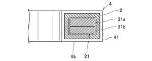
磁気コア2は、一例として図1,2に示すように、磁気コア2の周方向に沿って磁気コア2の内部に形成された空隙21を備え、空隙21内には、磁気センサ3を構成する後述のフラックスゲートセンサ素子31が収納されている。
As shown in FIGS. 1 and 2 as an example, the
磁気センサ3は、一例として図1,2に示すように、2つのフラックスゲートセンサ素子31a,31b(以下、特に区別しないときには「センサ素子31」ともいう)、差動増幅部32、および同期検波部33を備えている。各センサ素子31は、図示はしないが、一例として、同一形状に形成された円環状の絶縁基材の表面に検出巻線が同じ巻回数だけ巻回されてそれぞれ構成されている。また、各センサ素子31は、互いの検出巻線の巻線方向が互いに逆向きとなるように直列に接続され、かつ、図2に示すように、互いに重ね合わされた状態で磁気コア2の空隙21内に配設されている(磁気コア2に組み込まれている)。また、直列に接続された2つの検出巻線の各非接続端部(互いに接続されない側の端部)には引き出し線31c,31dがそれぞれ接続されると共に、各検出巻線の接続端部(互いに接続さる側の端部)には引き出し線31eが接続されて、2つの検出巻線は、各引き出し線31c,31d,31eを介して差動増幅部32に接続されている。
As shown in FIGS. 1 and 2 as an example, the
この構成により、各センサ素子31a,31bは、信号生成部5から出力される後述の励磁電流I2(一定の周波数fの交流電流)が供給されているときに、互いの位相が反転する検出電圧Va,Vbをそれぞれの検出巻線間に発生させると共に、各検出電圧Va,Vbを各引き出し線31c,31d,31eを介して差動増幅部32に出力する。
With this configuration, each of the
差動増幅部32は、図1に示すように、各センサ素子31に各引き出し線31c,31d,31eを介して接続されて、各センサ素子31から出力される検出電圧Va,Vbを入力すると共に、その差分電圧(Va−Vb)を検出する。また、差動増幅部32は、検出した差分電圧(Va−Vb)を増幅して、差分信号S1として出力する。磁気コア2に挿通されている測定対象電線64に電流Iが流れているときには、測定対象電線64の周囲に発生している磁界によって磁気コア2内の磁束が変化し、これに伴って各検出電圧Va,Vbの振幅が変化する。このため、差分電圧(Va−Vb)および差分信号S1は、励磁電流I2の2倍の周波数(2f)の信号成分が電流Iの振幅によって変調された振幅変調信号となる。
As shown in FIG. 1, the
同期検波部33は、差動増幅部32から出力される差分信号S1を、信号生成部5から出力される後述の同期信号S2(励磁電流I2に同期した周波数(2f)の矩形波信号)で同期検波することにより、測定対象電線64に流れる電流Iの電流値I1に比例して振幅が変化する検出信号S3を出力する。
The
帰還巻線4は、図1に示すように、センサ素子31を覆うようにして磁気コア2の外表面に磁気コア2の周方向に沿って配設された複数の巻線(本例では一例として、2個の巻線4a,4b)が直列に接続されて構成されている。各巻線4a,4bは、図2に示すように、磁気コア2の外表面に導線41を、同じ巻回方向で、かつ同じ巻回数だけ巻回して構成されている。なお、図2は、巻線4b、および磁気コア2の内部構造を示すための磁気コア2における巻線4bが配設された部位の周方向と直交する平面での断面図であるが、図示はしないが、磁気コア2における巻線4aが配設された部位の断面も同様の断面図となる。
As shown in FIG. 1, the feedback winding 4 includes a plurality of windings (one example in this example) disposed on the outer surface of the
また、図1に示すように、巻線4aは、その一端部42が駆動部6に接続されると共に、その他端部43が検出抵抗7の一端に接続されている。巻線4bは、その一端部44が検出抵抗7の他端に接続されると共に、その他端部45が基準電位(回路グランドG)に接続されている。この構成により、各巻線4a,4bは検出抵抗7を介して直列に接続されている。
As shown in FIG. 1, the winding 4 a has one
信号生成部5は、一定周波数fの交流電流である励磁信号としての励磁電流I2を生成して、センサ素子31に出力する。また、信号生成部5は、励磁電流I2に同期した周波数(2f)の信号を生成して同期信号S2として同期検波部33に出力する。
The
駆動部6は、磁気センサ3の同期検波部33から出力される検出信号S3を入力すると共に駆動信号S4に増幅して、帰還巻線4を構成する巻線4aの一端部42に出力する。本例では、一例として、駆動部6は、図3に示すように、ボルテージフォロワ回路で構成されて、増幅した検出信号S3を非反転の状態で駆動信号S4に増幅して出力する。この場合、帰還巻線4および検出抵抗7には、駆動部6から駆動信号S4が出力(印加)されることにより、駆動電流Idが流れる。このため、磁気コア2内には、駆動電流Idが帰還巻線4を流れることによって、磁束が発生する。駆動部6は、この駆動電流Idが帰還巻線4を流れることによって磁気コア2に発生する磁束で、測定対象電線64に電流Iが流れることによって磁気コア2に発生する磁束を打ち消すように(ゼロフラックス状態となるように)、つまり、磁気センサ3から出力される検出信号S3の振幅を低下させる(ゼロに近づける)ように、駆動信号S4の振幅(電圧)を制御する。
The
検出抵抗7は、図1,3に示すように、帰還巻線4を含む駆動電流Idの電流路内に配設されて、帰還巻線4に流れる駆動電流Idを電圧Vdに変換する。上記したように、本例では一例として、検出抵抗7は、帰還巻線4を構成する巻線4aと巻線4bとの間に配設されている。なお、検出抵抗7の配設位置は、これに限定されるものではなく、例えば、図示はしないが、巻線4aの他端部43と巻線4bの一端部44とを直接接続して、巻線4bの他端部45と基準電位(回路グランドG)との間に検出抵抗7を配設する構成を採用することもできる。
As shown in FIGS. 1 and 3, the
差動検出部8は、検出抵抗7に接続されて、この検出抵抗7に両端間電圧として発生する電圧Vdを検出すると共に、増幅して電圧信号Soとして出力する。共振防止回路9は、図1,3に示すように、帰還巻線4を構成するすべての巻線(本例では、2つの巻線4a,4b)のそれぞれに並列に接続されている。また、本例では一例として共振防止回路9は、図3に示すように、第1抵抗9a(例えば、10kΩ程度の抵抗)およびコンデンサ9b(例えば、500pF程度のコンデンサ)の直列回路を含んで構成されている。
The
以上のようにして構成された電流検出装置61は、測定対象電線64に流れる電流Iを、この電流Iが低周波領域fL(図5参照)に含まれる周波数の信号のときには、磁気センサ3を使用したゼロフラックス方式の電流検出装置として機能して検出し、この電流Iが高周波領域fH(図5参照)に含まれる周波数の信号のときには、帰還巻線4をCTとして使用する電流検出装置として機能して検出する。
The
また、この電流検出装置61では、共振防止回路9のインピーダンス(本例では、共振防止回路9を構成する第1抵抗9aおよびコンデンサ9bの直列回路のインピーダンス)の周波数特性が図5において実線で示す特性となるように、第1抵抗9aの抵抗値R1およびコンデンサ9bの静電容量値が予め規定されている。具体的には、電流検出装置61がゼロフラックス方式の電流検出装置として機能する低周波領域fL、および励磁電流I2の周波数fを含む周波数領域では、コンデンサ9bのインピーダンス成分が十分に大きい値(抵抗値R1よりも十分に大きい値)となるように、つまり、直列回路のインピーダンスが十分に大きい値となるように、この抵抗値R1およびこの静電容量値が規定されている。また、電流検出装置61において帰還巻線がCTとして機能する高周波領域fHでの特に共振の発生し易い周波数領域(図5において斜線を付した周波数領域)では、コンデンサ9bのインピーダンス成分が十分に小さい値(抵抗値R1よりも十分に小さい値)となって、直列回路のインピーダンスが抵抗値R1となるように、この抵抗値R1およびこの静電容量値が規定されている。この第1抵抗9aの抵抗値R1は、高周波領域fHでの上記の共振の発生を確実に防止(回避)し得る低抵抗値に規定されている。
Further, in this
処理部62は、例えば、A/D変換器、メモリおよびCPU(いずれも図示せず)を備えて構成されて、電流検出装置61から出力される電圧信号Soの電圧値V1を測定すると共に、この測定した電圧値V1に基づいて測定対象電線64に流れる電流Iの電流値I1を算出(測定)する。また、処理部62は、測定した電流値I1を出力部63に出力する。
The
出力部63は、一例として、LCDなどのディスプレイ装置で構成されて、処理部62から出力された電流値I1を画面に表示する。なお、出力部63は、ディスプレイ装置に代えて、種々のインターフェース回路で構成してもよく、例えば、メディアインターフェース回路としてリムーバブルメディアに電流値I1を記憶させたり、ネットワークインターフェース回路としてネットワーク経由で外部装置に電流値I1を伝送させたりする構成を採用することもできる。
For example, the
次に、電流検出装置61および測定装置MSの各動作について、図面を参照して説明する。
Next, each operation of the
上記したように、電流検出装置61では、低周波領域fLにおいては、信号生成部5が、帰還巻線4に対して周波数fの励磁電流I2を出力すると共に、フラックスゲート型の磁気センサ3における同期検波部33に同期信号S2を出力する。
As described above, in the
この状態において、磁気センサ3では、この励磁電流I2の供給を受けて作動する2つのセンサ素子31a,31bが、互いの位相が反転すると共に、測定対象電線64に流れる電流Iの電流値I1に応じて振幅が変化する検出電圧Va,Vbをそれぞれ出力する。差動増幅部32は、この検出電圧Va,Vbの差分電圧(Va−Vb)を検出して、差分信号S1を出力する。同期検波部33は、この差分信号S1を同期信号S2で同期検波することにより、測定対象電線64に流れる電流Iの電流値I1に比例して振幅が変化する検出信号S3を出力する。
In this state, in the
次いで、駆動部6は、磁気センサ3から出力される検出信号S3を入力すると共に、駆動信号S4に増幅して、帰還巻線4に出力することで、帰還巻線4に駆動電流Idを供給する。また、駆動部6は、検出信号S3の振幅(電圧)が低下する(ゼロに近づく)ように、駆動信号S4の振幅(電圧)を制御する(つまり、駆動電流Idの電流値を制御する)。この場合、検出信号S3の振幅(電圧)がゼロになっている状態では、磁気コア2に発生している全磁束がゼロになっている状態、つまり、測定対象電線64に電流Iが流れることによって磁気コア2に発生する磁束が、帰還巻線4に駆動電流Idが流れることによって磁気コア2に発生する磁束を打ち消している状態(ゼロフラックス状態)となっている。つまり、駆動部6は、電流値が電流Iの電流値I1と比例する駆動電流Idを出力している状態となっている。
Next, the
続いて、帰還巻線4を構成する2つの巻線4a,4b間に配設された検出抵抗7が、この駆動電流Idを電圧Vdに変換し、差動検出部8が、この電圧Vdを検出して電圧信号Soとして出力する。上記したように、駆動電流Idの電流値は電流Iの電流値I1と比例した状態に維持されているため、電流検出装置61から出力される電圧信号Soもまた、その電圧値V1(振幅)が電流Iの電流値I1に比例した信号となっている。
Subsequently, the
このようにして、電流検出装置61がゼロフラックス方式の電流検出装置として機能する低周波領域fLでは、上記したように、共振防止回路9のインピーダンス(主として、コンデンサ9bのインピーダンス)は十分に大きい値であるため、各巻線4a,4bに並列に接続されている共振防止回路9を経由して励磁電流I2の信号成分(周波数f)が検出抵抗7に流れ込む事態の発生が大幅に低減されている。これにより、電流検出装置61は、電圧Vdの検出に際してノイズ成分となる励磁電流I2の信号成分(周波数f)が検出抵抗7に流れ込むことに起因するS/N比の低下を確実に回避することが可能となっている。
Thus, in the low frequency region fL in which the
処理部62は、電流検出装置61から出力される電圧信号Soの電圧値V1を測定すると共に、この測定した電圧値V1に基づいて測定対象電線64に流れる電流Iの電流値I1を算出(測定)して出力部63に出力する。出力部63は、この電流値I1を画面に表示する。これにより、測定装置MSによる電流Iの電流値I1の測定が完了する。
The
また、電流検出装置61では、高周波領域fHにおいては、帰還巻線4がCTとして動作する。この状態においては、帰還巻線4には、測定対象電線64に電流Iが流れることによって磁気コア2に発生する磁束に比例した電圧が誘起され、帰還巻線4および検出抵抗7には、この誘起された電圧に比例した電流が流れる。検出抵抗7は、この電流を電圧Vdに変換し、差動検出部8が、この電圧Vdを検出して電圧信号Soとして出力する。上記したように、検出抵抗7に流れる電流の電流値は電流Iの電流値I1と比例しているため、電流検出装置61から出力される電圧信号Soもまた、その電圧値V1(振幅)が電流Iの電流値I1に比例した信号となっている。
In the
処理部62は、電流検出装置61から出力される電圧信号Soの電圧値V1を測定すると共に、この測定した電圧値V1に基づいて測定対象電線64に流れる電流Iの電流値I1を算出(測定)して出力部63に出力する。出力部63は、この電流値I1を画面に表示する。これにより、測定装置MSによる電流Iの電流値I1の測定が完了する。
The
帰還巻線4がCTとして動作し始める高周波領域fH内の低周波側においては、磁気センサ3および駆動部6の利得は大幅に低下し、また信号生成部5の利得も大幅に低下した状態となっている。この場合において、信号生成部5から出力されている励磁電流I2の振幅が十分に低くなっていないこともあり得るが、このときの共振防止回路9のインピーダンスは、図5に示すように、この励磁電流I2の影響を受けて帰還巻線4に漏れ込む周波数fの信号成分を十分に減衰させ得る大きさに維持されていることから、S/N比の低下は回避されている。
On the low frequency side in the high frequency region fH where the feedback winding 4 starts to operate as CT, the gains of the
一方、帰還巻線4がCTとして動作する高周波領域fH内の主たる領域(図5において斜線を付した周波数領域)では、共振防止回路9を構成するコンデンサ9bのインピーダンス成分が十分に小さい値(抵抗値R1よりも十分に小さい値)となって、直列回路のインピーダンスが抵抗値R1となる。これにより、寄生容量に起因して帰還巻線4(巻線4a,4b)に生じる虞のある共振については、共振防止回路9によって確実に防止される。
On the other hand, in the main region (frequency region hatched in FIG. 5) in the high frequency region fH in which the feedback winding 4 operates as CT, the impedance component of the
このようにして、この電流検出装置61および測定装置MSによれば、帰還巻線4を構成する複数の巻線(上記の例では、2個の巻線4a,4b)のそれぞれに、第1抵抗9aおよびコンデンサ9bの直列回路を含む共振防止回路9を並列に接続したことにより、電流検出装置61がゼロフラックス方式の電流検出装置として機能する低周波領域fLでは、この直列回路を構成するコンデンサ9bのインピーダンスが十分に大きい値(電流Iが直流または直流に近い周波数の信号のときには無限大に近い極めて大きな値)となることから(つまり、共振防止回路9のインピーダンスが十分に大きい値となることから)、この共振防止回路9を経由して励磁電流I2の信号成分(周波数f)が検出抵抗7に流れ込む事態の発生を大幅に低減でき、S/N比の低下を確実に回避することができる。また、帰還巻線4がCTとして機能する高周波領域fHでは、この直列回路を構成するコンデンサ9bのインピーダンスが十分に小さい値となることから(つまり、共振防止回路9のインピーダンスが第1抵抗9aの抵抗値R1(十分に小さい抵抗値)となることから)、寄生容量に起因して生じる虞のある帰還巻線4(巻線4a,4b)での共振の発生を確実に防止することができる。
Thus, according to the
なお、上記した駆動部6については上記した構成に限定されるものではない。例えば、図4に示すように、ボルテージフォロワ回路および反転増幅回路を使用した駆動部6Aを採用することもできる。この駆動部6Aでは、ボルテージフォロワ回路と反転増幅回路の双方に検出信号S3を入力し、ボルテージフォロワ回路の出力を帰還巻線4の一方の端部(巻線4aの一端部42)に接続し、反転増幅回路の出力を帰還巻線4の他方の端部(巻線4bの他端部45)に接続する。この駆動部6Aを有する電流検出装置61および測定装置MSにおいても、上記した駆動部6を有する電流検出装置61および測定装置MSと同等の効果を奏することができる。なお、上記した電流検出装置61の各構成要素と同等の機能を有する構成要素には同一の符号を付して、重複する説明を省略する。
Note that the
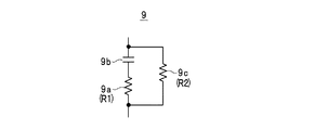
また、上記例では、第1抵抗9aおよびコンデンサ9bの直列回路だけで共振防止回路9を構成しているが、これに限定されるものではなく、例えば、図6に示す共振防止回路9のように、この直列回路に別の第2抵抗9cを直列に接続してもよい。この場合、この第2抵抗9cの抵抗値R2は、抵抗値R1よりも大きな値(十分に大きな値。例えば、100kΩ程度)に規定する。この共振防止回路9のインピーダンスの周波数特性では、電流検出装置61がゼロフラックス方式の電流検出装置として機能する低周波領域fLの低周波側におけるインピーダンスが、図5で破線で示すように抵抗値R2で頭打ちとなるが、上記したように、抵抗値R2を十分に大きな値に規定しておくことにより、この共振防止回路9を経由して励磁電流I2の信号成分(周波数f)が検出抵抗7に流れ込む事態の発生を十分に低減でき、S/N比の低下についても十分に回避することができる。
In the above example, the
また、磁気センサ3の一例としてフラックスゲート型磁気センサを挙げて説明したが、フラックスゲート型磁気センサに限定されず、ホール素子などの他の磁気センサを使用することもできる。ホール素子においても、ホール素子に供給する励磁信号としての励磁電流をスイッチで切り替える駆動方式が存在しており、この駆動方式においてはスイッチの切り換え時にサージ状のノイズが発生することが知られている(例えば、特許第3022957号公報参照)。このため、電流検出装置61の磁気センサとしてホール素子を使用する場合においても、フラックスゲート型磁気センサを使用した上記構成と同様にして、このサージ状のノイズの影響を低減することができる等の効果を奏することができる。
Moreover, although the flux gate type magnetic sensor was mentioned and demonstrated as an example of the
また、上記の電流検出装置61では、検出抵抗7が帰還巻線4に予め接続されて、検出抵抗7を別途用意する手間を省き得る構成を採用しているが、この構成に限定されるものではない。例えば、測定対象電線64に流れる電流Iの電流値I1をおおよそ予測し得る場合であって、かつこの電流値I1が広い範囲に亘る場合には、検出抵抗7に発生する電圧Vdの電圧値が差動検出部8の入力定格に合致するような抵抗値の検出抵抗7を適宜選択し得る構成とするのが望ましい。このため、図1に示すように、電流検出装置61において、駆動電流Idの電流路内に一対の抵抗接続端子46,46を配設して、所望の抵抗値の検出抵抗7をこの一対の抵抗接続端子46,46間に接続し得る構成とすることもできる。
Further, the
また、2個の巻線4a,4bを直列接続して帰還巻線4を構成する例を挙げて説明したが、図示はしないが、3つ以上の巻線を直列接続して帰還巻線を構成する構成においても、各巻線のそれぞれに上記の共振防止回路9を並列に接続することにより、上記した効果と同等の効果を奏することできる。また、電流検出装置61を備えた測定装置MSとして、電流測定装置を例に挙げて説明したが、電流検出装置61を備えた測定装置MSとしては、電流測定装置以外に電力測定装置など種々の測定装置とすることができる。
In addition, although an example in which the feedback winding 4 is configured by connecting two
2 磁気コア
3 磁気センサ
4 帰還巻線
4a,4b 巻線
5 信号生成部
6,6A 駆動部
7 検出抵抗
9 共振防止回路
11 測定対象電線
31 センサ素子
61 電流検出装置
I 電流
I1 電流値
I2 励磁電流
Id 駆動電流
S3 検出信号
MS 測定装置
Vd 電圧
DESCRIPTION OF
Claims (5)
前記帰還巻線は、前記磁気コアの周方向に沿って配置された複数の巻線が直列に接続されて構成され、
前記複数の巻線のそれぞれには、第1抵抗およびコンデンサの直列回路を含んで構成される共振防止回路が並列に接続されている電流検出装置。 An annular magnetic core into which the measurement target electric wire is inserted; a magnetic sensor that outputs a detection signal that is incorporated in the magnetic core and that changes in amplitude in proportion to the current value of the current that flows through the measurement target electric wire; A feedback winding configured by winding a conducting wire around the outer surface of the magnetic core; a drive unit that inputs the detection signal and supplies a drive current to the feedback winding that reduces the amplitude of the detection signal; and the drive A current detection device comprising a pair of resistance connection terminals disposed in a current path of a current and connected to a detection resistance for converting the drive current into a voltage;
The feedback winding is configured by connecting a plurality of windings arranged in the circumferential direction of the magnetic core in series,
A current detection device in which a resonance prevention circuit including a series circuit of a first resistor and a capacitor is connected in parallel to each of the plurality of windings.
前記帰還巻線は、前記磁気コアの周方向に沿って配置された複数の巻線が直列に接続されて構成され、
前記複数の巻線のそれぞれには、第1抵抗およびコンデンサの直列回路を含んで構成される共振防止回路が並列に接続されている電流検出装置。 An annular magnetic core into which the measurement target electric wire is inserted; a magnetic sensor that outputs a detection signal that is incorporated in the magnetic core and that changes in amplitude in proportion to the current value of the current that flows through the measurement target electric wire; A feedback winding formed by winding a conducting wire on the outer surface of the magnetic core, a signal generator for outputting an excitation signal to the magnetic sensor, and a drive current for inputting the detection signal and reducing the amplitude of the detection signal And a detection resistor that is disposed in the current path of the drive current and converts the drive current into a voltage and outputs the voltage, and converted by the detection resistor. A current detection device for detecting a voltage as a current value of a current flowing through the measurement target wire,
The feedback winding is configured by connecting a plurality of windings arranged in the circumferential direction of the magnetic core in series,
A current detection device in which a resonance prevention circuit including a series circuit of a first resistor and a capacitor is connected in parallel to each of the plurality of windings.
前記検出抵抗によって変換された前記電圧に基づいて前記電流値を測定する処理部と、
前記測定された電流値を出力する出力部とを備えている測定装置。 The current detection device according to any one of claims 1 to 4,
A processing unit for measuring the current value based on the voltage converted by the detection resistor;
A measuring device comprising: an output unit that outputs the measured current value.
Priority Applications (3)
| Application Number | Priority Date | Filing Date | Title |
|---|---|---|---|
| JP2017128221A JP2019012002A (en) | 2017-06-30 | 2017-06-30 | Current detecting device and measuring device |
| DE102018210466.2A DE102018210466A1 (en) | 2017-06-30 | 2018-06-27 | Current measuring device and measuring device |
| JP2022136410A JP2022162171A (en) | 2017-06-30 | 2022-08-30 | Current sensing and measuring device |
Applications Claiming Priority (1)
| Application Number | Priority Date | Filing Date | Title |
|---|---|---|---|
| JP2017128221A JP2019012002A (en) | 2017-06-30 | 2017-06-30 | Current detecting device and measuring device |
Related Child Applications (1)
| Application Number | Title | Priority Date | Filing Date |
|---|---|---|---|
| JP2022136410A Division JP2022162171A (en) | 2017-06-30 | 2022-08-30 | Current sensing and measuring device |
Publications (1)
| Publication Number | Publication Date |
|---|---|
| JP2019012002A true JP2019012002A (en) | 2019-01-24 |
Family
ID=64662083
Family Applications (2)
| Application Number | Title | Priority Date | Filing Date |
|---|---|---|---|
| JP2017128221A Pending JP2019012002A (en) | 2017-06-30 | 2017-06-30 | Current detecting device and measuring device |
| JP2022136410A Pending JP2022162171A (en) | 2017-06-30 | 2022-08-30 | Current sensing and measuring device |
Family Applications After (1)
| Application Number | Title | Priority Date | Filing Date |
|---|---|---|---|
| JP2022136410A Pending JP2022162171A (en) | 2017-06-30 | 2022-08-30 | Current sensing and measuring device |
Country Status (2)
| Country | Link |
|---|---|
| JP (2) | JP2019012002A (en) |
| DE (1) | DE102018210466A1 (en) |
Cited By (2)
| Publication number | Priority date | Publication date | Assignee | Title |
|---|---|---|---|---|
| CN112415249A (en) * | 2020-11-09 | 2021-02-26 | 武汉大学 | A zero-flux current transformer and error modulation method |
| CN113030550A (en) * | 2021-05-25 | 2021-06-25 | 珠海多创科技有限公司 | Non-contact voltage sensor |
Families Citing this family (3)
| Publication number | Priority date | Publication date | Assignee | Title |
|---|---|---|---|---|
| JP7674306B2 (en) * | 2022-07-07 | 2025-05-09 | 横河電機株式会社 | Current Sensors |
| CN120380350A (en) * | 2022-12-19 | 2025-07-25 | 日置电机株式会社 | Current sensor and measuring device |
| JP2026069805A (en) * | 2024-10-15 | 2026-04-27 | 日置電機株式会社 | Current detection device and measuring device |
Citations (6)
| Publication number | Priority date | Publication date | Assignee | Title |
|---|---|---|---|---|
| JPS54127151U (en) * | 1978-02-27 | 1979-09-05 | ||
| JPH07318623A (en) * | 1994-05-25 | 1995-12-08 | Chodendo Sensor Kenkyusho:Kk | Squid fluximeter |
| JPH11332844A (en) * | 1998-05-29 | 1999-12-07 | Toshiba Corp | SQUID magnetic flux sensor |
| JP2012247191A (en) * | 2011-05-25 | 2012-12-13 | Hioki Ee Corp | Current detection device |
| JP2015206596A (en) * | 2014-04-17 | 2015-11-19 | 日置電機株式会社 | Current sensor and measuring device |
| JP2017083220A (en) * | 2015-10-26 | 2017-05-18 | 日置電機株式会社 | Current sensor and measuring device |
-
2017
- 2017-06-30 JP JP2017128221A patent/JP2019012002A/en active Pending
-
2018
- 2018-06-27 DE DE102018210466.2A patent/DE102018210466A1/en not_active Withdrawn
-
2022
- 2022-08-30 JP JP2022136410A patent/JP2022162171A/en active Pending
Patent Citations (6)
| Publication number | Priority date | Publication date | Assignee | Title |
|---|---|---|---|---|
| JPS54127151U (en) * | 1978-02-27 | 1979-09-05 | ||
| JPH07318623A (en) * | 1994-05-25 | 1995-12-08 | Chodendo Sensor Kenkyusho:Kk | Squid fluximeter |
| JPH11332844A (en) * | 1998-05-29 | 1999-12-07 | Toshiba Corp | SQUID magnetic flux sensor |
| JP2012247191A (en) * | 2011-05-25 | 2012-12-13 | Hioki Ee Corp | Current detection device |
| JP2015206596A (en) * | 2014-04-17 | 2015-11-19 | 日置電機株式会社 | Current sensor and measuring device |
| JP2017083220A (en) * | 2015-10-26 | 2017-05-18 | 日置電機株式会社 | Current sensor and measuring device |
Cited By (2)
| Publication number | Priority date | Publication date | Assignee | Title |
|---|---|---|---|---|
| CN112415249A (en) * | 2020-11-09 | 2021-02-26 | 武汉大学 | A zero-flux current transformer and error modulation method |
| CN113030550A (en) * | 2021-05-25 | 2021-06-25 | 珠海多创科技有限公司 | Non-contact voltage sensor |
Also Published As
| Publication number | Publication date |
|---|---|
| JP2022162171A (en) | 2022-10-21 |
| DE102018210466A1 (en) | 2019-01-03 |
Similar Documents
| Publication | Publication Date | Title |
|---|---|---|
| JP6625395B2 (en) | Current sensors and measuring devices | |
| JP2022162171A (en) | Current sensing and measuring device | |
| JP6672259B2 (en) | Current converter with fluxgate detector | |
| US9383392B2 (en) | Current sensor | |
| JP6305419B2 (en) | Insulated current measuring device and insulated current judging method | |
| JP4607753B2 (en) | Voltage measuring device and power measuring device | |
| US9606147B2 (en) | Apparatus for high bandwidth current sensing | |
| CN105308840B (en) | Method and apparatus for distinguishing electric arc | |
| JP6305184B2 (en) | Current sensor and measuring device | |
| KR20170090468A (en) | Current detection device | |
| JP2007163414A (en) | Variable capacitance circuit, voltage measuring device and power measuring device | |
| JP5710380B2 (en) | Current detector | |
| US20200249258A1 (en) | Sensor apparatus for measuring direct and alternating currents | |
| WO2023157902A1 (en) | Excitation circuit, current sensor, and measuring device | |
| JP6829139B2 (en) | Current sensor and measuring device | |
| JP4882934B2 (en) | Current measuring device | |
| JP2016194483A (en) | Current detection device | |
| KR102039268B1 (en) | An Alternating and Direct Current Detection Circuit | |
| JP2019012004A (en) | Current detection device and measuring device | |
| JP5758229B2 (en) | Magnetic field detector | |
| KR102039270B1 (en) | A Ground-Fault Current Detection Circuit | |
| JP4607744B2 (en) | Voltage measuring device and power measuring device | |
| JP2022128771A (en) | Cable run monitoring device, cable run monitoring system and cable run monitoring method | |
| KR102039271B1 (en) | A Earth Leakage Current Detection Circuit | |
| JP2022083398A (en) | Input circuit and measuring device |
Legal Events
| Date | Code | Title | Description |
|---|---|---|---|
| A621 | Written request for application examination |
Free format text: JAPANESE INTERMEDIATE CODE: A621 Effective date: 20200420 |
|
| A977 | Report on retrieval |
Free format text: JAPANESE INTERMEDIATE CODE: A971007 Effective date: 20210212 |
|
| A131 | Notification of reasons for refusal |
Free format text: JAPANESE INTERMEDIATE CODE: A131 Effective date: 20210302 |
|
| A601 | Written request for extension of time |
Free format text: JAPANESE INTERMEDIATE CODE: A601 Effective date: 20210423 |
|
| A521 | Request for written amendment filed |
Free format text: JAPANESE INTERMEDIATE CODE: A523 Effective date: 20210628 |
|
| A131 | Notification of reasons for refusal |
Free format text: JAPANESE INTERMEDIATE CODE: A131 Effective date: 20211012 |
|
| A601 | Written request for extension of time |
Free format text: JAPANESE INTERMEDIATE CODE: A601 Effective date: 20211209 |
|
| A521 | Request for written amendment filed |
Free format text: JAPANESE INTERMEDIATE CODE: A523 Effective date: 20220126 |
|
| A02 | Decision of refusal |
Free format text: JAPANESE INTERMEDIATE CODE: A02 Effective date: 20220531 |
|
| A521 | Request for written amendment filed |
Free format text: JAPANESE INTERMEDIATE CODE: A523 Effective date: 20220830 |
|
| C60 | Trial request (containing other claim documents, opposition documents) |
Free format text: JAPANESE INTERMEDIATE CODE: C60 Effective date: 20220830 |
|
| A911 | Transfer to examiner for re-examination before appeal (zenchi) |
Free format text: JAPANESE INTERMEDIATE CODE: A911 Effective date: 20220906 |
|
| C21 | Notice of transfer of a case for reconsideration by examiners before appeal proceedings |
Free format text: JAPANESE INTERMEDIATE CODE: C21 Effective date: 20220913 |
|
| A912 | Re-examination (zenchi) completed and case transferred to appeal board |
Free format text: JAPANESE INTERMEDIATE CODE: A912 Effective date: 20221104 |
|
| C211 | Notice of termination of reconsideration by examiners before appeal proceedings |
Free format text: JAPANESE INTERMEDIATE CODE: C211 Effective date: 20221108 |
|
| C22 | Notice of designation (change) of administrative judge |
Free format text: JAPANESE INTERMEDIATE CODE: C22 Effective date: 20230221 |
|
| C22 | Notice of designation (change) of administrative judge |
Free format text: JAPANESE INTERMEDIATE CODE: C22 Effective date: 20230404 |