JP2019013116A - Electrically-driven travel control device and electrically-driven fork lift - Google Patents
Electrically-driven travel control device and electrically-driven fork lift Download PDFInfo
- Publication number
- JP2019013116A JP2019013116A JP2017129754A JP2017129754A JP2019013116A JP 2019013116 A JP2019013116 A JP 2019013116A JP 2017129754 A JP2017129754 A JP 2017129754A JP 2017129754 A JP2017129754 A JP 2017129754A JP 2019013116 A JP2019013116 A JP 2019013116A
- Authority
- JP
- Japan
- Prior art keywords
- brake
- electric
- brake pedal
- depression
- amount
- Prior art date
- Legal status (The legal status is an assumption and is not a legal conclusion. Google has not performed a legal analysis and makes no representation as to the accuracy of the status listed.)
- Granted
Links
Images



Landscapes
- Electric Propulsion And Braking For Vehicles (AREA)
- Braking Systems And Boosters (AREA)
- Regulating Braking Force (AREA)
- Forklifts And Lifting Vehicles (AREA)
Abstract
Description
本発明は、電動走行制御装置および電動フォークリフトに関する。 The present invention relates to an electric travel control device and an electric forklift.
電動車両、たとえば電動フォークリフトでは、アクセルペダルとブレーキペダルの踏込量に基づいて走行用電動モータを駆動制御する。アクセルペダルを解放すると回生制御により回生ブレーキ力が得られる。アクセルペダルを解放してブレーキペダルを踏み込むと、ブレーキペダルの踏み込み量に応じた回生ブレーキ力が得られる(たとえば、特許文献1)。 In an electric vehicle, for example, an electric forklift, the driving electric motor is driven and controlled based on the amount of depression of an accelerator pedal and a brake pedal. When the accelerator pedal is released, regenerative braking force is obtained by regenerative control. When the accelerator pedal is released and the brake pedal is depressed, a regenerative braking force corresponding to the amount of depression of the brake pedal is obtained (for example, Patent Document 1).
しかしながら、所定の走行条件下では、回生ブレーキだけでは必要なブレーキ力が発揮できないことがある。 However, under a predetermined traveling condition, the necessary braking force may not be exhibited only with the regenerative brake.
第1の態様によれば、アクセルペダルと、ブレーキペダルと、駐車ブレーキ指令に基づき車輪に電磁制動力を与える電磁駐車ブレーキ装置とを備える電動車両に用いられる電動走行制御装置は、前記アクセルペダルの踏込量および/または前記ブレーキペダルの踏込量に基づいて走行用電動モータを駆動制御する制御部を備え、前記制御部は、前記ブレーキペダルの踏込量が所定値以上であり、かつ、車速が所定値以上である条件が成立すると前記電磁駐車ブレーキ装置を動作させる。
第2の態様による電動フォークリフトは、アクセルペダルと、ブレーキペダルと、前記アクセルペダルの踏込量を検出するアクセルセンサと、前記ブレーキペダルの踏込量を検出するブレーキセンサと、車速を検出する車速センサと、電磁駐車ブレーキ装置と、走行用電動モータと、第1の態様の電動走行制御装置とを備える。
According to the first aspect, an electric travel control device used in an electric vehicle including an accelerator pedal, a brake pedal, and an electromagnetic parking brake device that applies an electromagnetic braking force to a wheel based on a parking brake command is provided on the accelerator pedal. A control unit that controls driving of the electric motor for travel based on the depression amount and / or the depression amount of the brake pedal, wherein the control unit has a depression amount of the brake pedal equal to or greater than a predetermined value and a vehicle speed is predetermined; When the condition equal to or greater than the value is satisfied, the electromagnetic parking brake device is operated.
The electric forklift according to the second aspect includes an accelerator pedal, a brake pedal, an accelerator sensor that detects a depression amount of the accelerator pedal, a brake sensor that detects a depression amount of the brake pedal, and a vehicle speed sensor that detects a vehicle speed. The electromagnetic parking brake device, the electric motor for traveling, and the electric traveling control device of the first aspect are provided.
本発明によれば、ブレーキペダル踏込量と車速が所定条件下において、必要なブレーキ力を得ることができる。 According to the present invention, it is possible to obtain a necessary braking force under a predetermined condition of the brake pedal depression amount and the vehicle speed.
以下の説明は、本発明の一実施の形態の走行車両として電動フォークリフトを例に挙げて行う。
図1は、実施の形態における電動フォークリフトの側面図である。電動フォークリフト1は、走行用車輪2および運転席3が設けられた車両本体4と、車両本体4の前部に設けられた荷役装置5とを備えている。荷役装置5は、車両本体4の前部に固定される左右一対の外マスト6と、外マスト6に支持案内されて昇降自在な左右一対の内マスト7と、内マスト7に昇降可能に配置された昇降体であるキャリッジ8と、キャリッジ8の前面側に設けられて荷物を保持する左右一対のフォーク9とを備えている。
In the following description, an electric forklift is taken as an example of a traveling vehicle according to an embodiment of the present invention.
FIG. 1 is a side view of an electric forklift according to an embodiment. The
キャリッジ8と外マスト6とに亘ってチェーン10が設けられており、チェーン10の中間部は、内マスト7の上部に設けられたガイド輪であるシーブ11に巻装されてキャリッジ8を吊持している。内マスト7は、外マスト6に固定支持されたリフトシリンダ12により昇降される。したがって、リフトシリンダ12により内マスト7が昇降されると、シーブ11の昇降により、チェーン10を介して、キャリッジ8とキャリッジ8に設けられたフォーク9とが昇降されることになる。なお、リフトシリンダ12は、外マスト6の左右に配置されるとともに、チェーン10についても左右に配置されている。また、外マスト6と車両本体4との間には、外マスト6を前後方向に傾動させるチルトシリンダ13が設けられている。
A
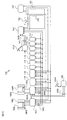
図2は、本発明を電動フォークリフト1に適用した実施の形態における電動システム100の構成図である。図3はとくに制動装置を構成する要素間で授受される信号の流れを概念的に示す図である。
電動フォークリフト1は、図2に示すように、走行用電動モータ(以下、走行モータ)104L,104Rにより左右の前輪に駆動力を与えて走行する。電動システム100は、アクセルペダル101Aの踏込量を検出するアクセルセンサ101と、ブレーキペダル102Aの踏込量を検出するブレーキセンサ102と、アクセルセンサ101からアクセル踏込量信号SADが入力されて電動フォークリフト1を制御する制御部であるビークルコントロールモジュール(以下、VCM)103と、左右の前輪に独立して設けられ左右の車輪に駆動力を与える走行モータ104R,104Lと、VCM103から出力されるモータ駆動信号SML,SMRにより駆動制御されて走行モータ104R,104Lを独立制御するインバータ105R,105Lと、走行モータ104L,104R、すなわち車輪に制動力を与えて電動フォークリフト1を制動する電磁ブレーキ106R,106Lとを備えている。ブレーキセンサ102から出力されるブレーキ踏込量信号SBDはインバータ105Rを経由してVCM103に送られる。
電磁ブレーキ106R,106Lは駐車ブレーキ指令に基づいた駐車ブレーキとしての役割と、後述するような緊急ブレーキとしての役割がある。
なお、実施の形態の電動フォークリフト1は、液圧ブレーキ等のサービスブレーキを搭載していないので、以下で詳細に説明する緊急ブレーキで駐車用電磁ブレーキを使用する条件下以外では、メカニカルに車輪に制動力を与える機能はない。実施の形態の制動装置は、いわゆるブレーキバイワイヤ方式の制動装置である。
FIG. 2 is a configuration diagram of an
As shown in FIG. 2, the
The
Since the
以下の説明では、左右の走行モータ104R.104Lに符号104を付し、一対のインバータ105R,105Lに符号105を付し、電磁ブレーキ106R,106Lに符号106を付して説明する場合もある。
In the following description, the left and right traveling
走行モータ104には回転センサ104Sが設けられ、回転センサ104Sで得た回転数信号SR(図3参照)はインバータ105Rを経由してVCM103に入力される。VCM103は回転数信号SRに基づき車速VVを演算する。換言すると、回転センサ104Sは、電動フォークリフト1の車速を検出する車速センサとして機能する。
電磁ブレーキ106は、通電時に電磁力が発生してブレーキパッドがディスクから開放され、非通電時に付勢力でブレーキパッドがディスクを挟圧して車輪を制動、すなわち車輪に電磁制動力を与えるネガブレーキである。
The travel motor 104 is provided with a
The
走行モータ104としてたとえば3相交流電動機が用いられる。この場合、インバータ105R,105Lは、UVW各相ごとに一対の半導体スイッチングトランジスタを備えている。VCM103からインバータ105に入力されるモータ駆動信号SML,SMRにより各相の半導体スイッチングトランジスタがスイッチング制御される。インバータ105の各相半導体スイッチングトランジスタにはバッテリ107から強電系の電力が印加されている。モータ駆動信号SML,SMRによるスイッチング制御により必要な電力が各相のコイルに通電され、走行モータ104は必要な駆動トルクで前輪を駆動する。
For example, a three-phase AC motor is used as the traveling motor 104. In this case, the
VCM103は、入力されるアクセル踏込量信号SADおよびブレーキ踏込量信号SBDと、入力される回転数信号SRに基づき演算される車速VVとに基づいて、走行モータ104に与える駆動トルクを演算する。VCM103は、ブレーキセンサ102から送出されるブレーキペダル102Aの踏込量に基づいてオペレータが要求する制動力を演算する。VCM103は、演算された制動力が回生ブレーキで発揮できるように各相の半導体スイッチングトランジスタにモータ駆動信号SML,SMRを与える。これによりブレーキ踏込量に基づく回生ブレーキが得られる。後述する所定の条件が成立するとVCM103は回生ブレーキで得られる制動力が不足すると判断する。このとき、VCM103は、最大の回生ブレーキが得られるように半導体スイッチングトランジスタをスイッチングするとともに、電磁ブレーキ106を所定時間だけ2回、所定周期でオンオフ(開閉)する。
The VCM 103 calculates a driving torque to be applied to the travel motor 104 based on the input accelerator depression amount signal SAD and brake depression amount signal SBD, and the vehicle speed VV calculated based on the input rotation speed signal SR. The VCM 103 calculates the braking force requested by the operator based on the depression amount of the
なお、図2において、電動システム100は、以上説明した電動駆動装置以外にも、前後進スイッチ(FRSW)111、シートベルトスイッチ112(Seat Belt SW)、シートスイッチ(SeatSW)113、パーキングブレーキスイッチ(PKB SW)114、キースイッチ(KEY SW)115、(FTC SW)116、メータ(Meter)117、パワーステアリングコントローラ(PSCONT)118、ポンプ用インバータ(Pump Inverter)119を備えている。
In FIG. 2, the
バッテリ107の正極端子と走行用インバータ105L,105Rとの間にはメインコンタクタ121が配置され、そのリレー制御端子はバッテリスイッチ(BATSW)122を介してVCM103と接続されている。バッテリスイッチ122が操作されてリレー制御端子への通電が遮断されるとメインコンタクタ121が開き、バッテリ107と走行用インバータ105L,105Rとの間の電源ライン、すなわち、モータ駆動用電源ラインが遮断される。キースイッチ113がオフされたとき、VCM103はメインコンタクタ121のリレー制御端子への通電を停止するので、バッテリ107と走行用インバータ105L,105Rとが遮断される。
A
また、バッテリ107の正極端子と走行用インバータ105L,105Rとの間にはインバータリレー123が配置され、そのリレー制御端子はVCM103と接続されている。メインコンタクタ121の焼き付きをVCM103が検出すると、VCM103はインバータリレー123のリレー制御端子への通電を遮断する。これにより、インバータリレー123が開き、バッテリ107と走行用インバータ105L,105Rとの間の電源ライン、すなわち、インバータに実装される半導体スイッチングトランジスタの駆動用電源ラインが遮断される。
An inverter relay 123 is disposed between the positive terminal of the
以上説明した電動フォークリフト1の走行駆動制御をより具体的に説明する。本実施の形態の電動フォークリフト1のVCM103は、アクセルセンサ101および/またはブレーキセンサ102からの出力に基づいて、走行モータ104の駆動制御を行う。以下、力行運転時と回生運転時とに分けて駆動制御の説明を行う。
The travel drive control of the
(力行運転)
オペレータが前後進するためアクセルペダル101Aを踏み込むと、VCM103は、アクセル踏込量信号SADに基づき要求トルクを演算し、車速VVも参照して走行モータ104を駆動制御する。すなわち、VCM103は、インバータ105の半導体スイッチングトランジスタをスイッチング制御するモータ駆動信号SML,SMRを生成してインバータ105の制御端子に出力する。VCM103からのモータ駆動信号SML,SMRによりインバータ105の半導体スイッチングトランジスタがスイッチング制御され、バッテリ107からインバータ105に印加されている直流電流が交流電流に変換され、走行モータ104のUVW各相に通電される。これにより、走行モータ104はオペレータが要求する走行トルクで駆動されて前輪が回転してフォークリフトが走行する。
(Power running)
When the operator depresses the
(回生運転)
アクセルペダル101Aが解放されるとオペレータの要求トルクがゼロとなり、走行モータ104は走行抵抗により駆動されて発電する。このとき、VCM103はいわゆる発電モードで走行モータ104を制御することにより回生制御が行われる。回生制御では、VCM103は、車速を勘案した回生制動力を走行モータ104に与えるため、インバータ105の半導体スイッチングトランジスタを駆動制御して回生電流を制御する。交流の回生電流はインバータ105で直流電流に変換されてバッテリ107を充電する。
アクセルペダル101Aが解放されているときにブレーキペダル102Aが踏込まれると、アクセルペダル101Aの解放で得られる回生ブレーキより大きな回生ブレーキが得られるような回生制御を行う。すなわち、VCM103はインバータ105の半導体スイッチングトランジスタをブレーキ踏込量に応じてスイッチングしてより大きな回生ブレーキ力を得る。
(Regenerative operation)
When the
When the
以上は一般的な電動車両における力行制御と回生制御の動作である。要約すると、力行運転時、インバータ105は、バッテリ107からの直流電流を交流電流に変換して走行モータ104に交流電流を印加し、これにより走行モータ104はアクセル踏込量である要求トルクに見合った走行駆動トルクで駆動される。回生運転時、車輪から回転トルクが走行モータ104に伝達され、走行モータ104は、交流電力(回生電力)を発生する。すなわち発電する。発生した交流電力は、インバータ105により直流電力に変換され、バッテリ107が充電される。すなわち、ブレーキペダルの踏込量に基づく要求制動トルクが得られるように走行モータの発電電力をバッテリに回収する。充電された電力は再び走行エネルギとして使用される。
The above is the operation of power running control and regenerative control in a general electric vehicle. In summary, during power running, the inverter 105 converts the direct current from the
VCM103は、さらに、車速がたとえば12km/h以上でブレーキペダル102Aの踏込量が所定値以上であることを検出すると、上述した回生制御に加えて、電磁ブレーキ106による制動制御(特定制動力制御)を行う。電磁ブレーキ106による制動制御では、走行時はブレーキ解放のために印加されているブレーキ電圧を所定時間遮断し、所定時間経過後に所定時間通電する制御を少なくとも2回ずつ行う。この結果、電磁ブレーキ106のブレーキパッドがディスクを所定時間挟圧して機械的な制動力を得、所定時間経過後に電圧が遮断されてブレーキパッドがディスクを所定時間開放する、いわゆるポンピングブレーキ制御が行われる。なお、ポンピングブレーキ制御を少なくとも2回行う場合に限定されず、1回でも良いし3回以上でも良く、電動フォークリフト1の車体の特性等に基づいて回数を決めることができる。
Further, when the
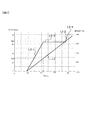
図4に、ブレーキペダル102Aが踏み込まれた場合における踏込量(ストローク)と、踏力と、減速度との関係を示す。図4において、特性L1はブレーキペダル102Aの踏込量と踏力との関係を示し、特性L2−1,L2−2,L2−3,L2−4はブレーキペダル102Aに加わる踏力と電動フォークリフト1の減速度との関係を示す。アクセルペダル101Aが解放されているときにブレーキペダル102Aが踏込まれると、特性L2−1,L2−2に示す減速度となるような回生ブレーキが得られるような回生制御が行われる。ブレーキペダル102Aの踏込量が第1所定値SB1までの場合には、減速度は特性L2−1のように、ブレーキペダル102Aの踏込量が大きい程減速度が大きくなる。ブレーキペダル102Aの踏込量が第1所定値SB1から第2所定値SB2までの場合には、減速度は特性L2−2に示すように、ブレーキペダル102Aの踏込量に関わらず特定の値となる。車速がたとえば12km/h以上でブレーキペダル102Aの踏込量が第2所定値SB2以上であることが検出されると、特性L2−3,L2−4に示す減速度が得られるように上述した回生制御に加えて、電磁ブレーキ106による制動制御が行われる。図示の通り、減速度の増加は、踏力との関係が特性L2−1に示す場合よりも特性L2−3の場合の方が大きい。なお、図4に示す踏込量、踏力、減速度の値は一例であり、実際の値は図示の値と異なる場合もある。
FIG. 4 shows the relationship between the depression amount (stroke), the depression force, and the deceleration when the
図5を参照して、VCM103の制動制御の処理手順を説明する。なお、図5の処理はVCM103のCPUなどの演算処理装置で実行される。
ステップS1において、アクセル踏込量信号SADに基づきアクセルペダル101Aが踏み込まれているかを判定し、肯定されるとステップS2において力行制御が実行される。ステップS1が否定されるとステップS3において、ブレーキ踏込量信号SBDに基づきブレーキペダル102Aが踏込まれているかを判定する。ステップS3が否定されるとステップS4において、アクセルペダル101Aの解放による回生制御が実行される。ステップS3が肯定されるとステップS5に進み、VCM103で演算された車速信号VVに基づき車速が12km/h以上か否かを判定する。ステップS5が否定されるとステップS6において、アクセルペダル101Aの解放による回生ブレーキよりも大きな回生ブレーキが発揮される回生制御が実行される(図4の特性L2−1,L2−2)。すなわち、アクセル踏込量信号SADに基づきアクセル踏込量がゼロ、かつ、ブレーキ踏込量信号SBDに基づく回生制御が実行される。
With reference to FIG. 5, the processing procedure of the braking control of the
In step S1, it is determined whether the
ステップS5が肯定されると、すなわち、車速が12km/h以上と判定されるとステップS7において、ブレーキ踏込量が第2所定値SB2以上か否かを判定する。ステップS7が肯定されるとステップS8において、アクセルペダル101A解放で、かつ、ブレーキペダル102Aの踏み込み量に基づく回生制御による制動力に加えて、電磁ブレーキ106をポンピング制御して得られる制動力が合算された大きな制動力が得られる(図4の特性L2−3,L2−4)。
ステップS5が肯定されたときの制動処理は緊急制動処理である。緊急制動処理では、ブレーキペダル102Aの踏込量が所定値SB2未満のときに得られる踏力と回生制動力の特性L2−1の傾きよりも急峻な傾きを有する特性L2−3に示すような大きな制動力が与えられる。
If step S5 is affirmed, that is, if the vehicle speed is determined to be 12 km / h or more, it is determined in step S7 whether or not the brake depression amount is equal to or greater than a second predetermined value SB2. If step S7 is affirmed, in step S8, the braking force obtained by pumping control of the
The braking process when step S5 is affirmed is an emergency braking process. In the emergency braking process, a large braking force as shown by a characteristic L2-3 having a steeper slope than the slope of the characteristic L2-1 of the depression force and the regenerative braking force obtained when the depression amount of the
上述した実施の形態によれば、次の作用効果が得られる。
(1)アクセルペダル101Aと、ブレーキペダル102Aと、駐車ブレーキ指令に基づいて車輪に電磁制動力を与える電磁ブレーキ106とを有する電動フォークリフト1に用いられる電動システム100は、アクセルペダル101Aの踏込量および/またはブレーキペダル102Aの踏込量に基づいて走行モータ104を駆動制御するVCM103を備える。VCM103は、ブレーキペダル102Aの踏込量が所定値以上であり、かつ、車速が所定値以上である条件が成立すると電磁ブレーキ106を動作させる。したがって、緊急時に電磁ブレーキ106を用いて必要な制動力を得ることができる。また、駐車ブレーキとしての電磁ブレーキ106を、緊急ブレーキとしても利用するので、部品点数の増加を抑制して、緊急時における制動力を得ることができる。
(2)VCM103は、上記の条件が成立すると、電磁ブレーキ106の作動、非作動を少なくとも2回行う特定制動制御を実行する。したがって、緊急時に十分な制動力を得ることができる。
According to the embodiment described above, the following operational effects can be obtained.
(1) The
(2) When the above condition is satisfied, the
(3)VCM103は、ブレーキペダル102Aの踏込量が第1所定値SB1未満の場合には、ブレーキペダル101Aの踏込量が大きい程大きな減速度が得られるように走行モータ104の発電電力を回収制御する。VCM103は、ブレーキペダル101Aの踏込量が第1所定値SB1から第2所定値SB2の場合には、ブレーキペダル101Aの踏込量に関わらず特定の減速度が得られるように走行モータ104の発電電力を回収制御する。VCM103は、車速が所定値以上のときにブレーキペダル101Aの踏込量が第2所定値SB2以上になる場合、特定制動力制御を実行する。したがって、緊急時には、走行モータ104による回生ブレーキと、電磁ブレーキ106とにより、高い制動力を得ることが可能になる。
(3) When the depression amount of the
(4)VCM103は、特定動力制御が実行される場合の発電電力の回収制御は、特定動力制御が実行されない場合に比べて大きな回生制動力が得られるように制御を実行する。したがって、緊急時に得られる制動力を高くすることができる。
(4) The
なお、上述した実施の形態では、電動フォークリフトを例に挙げて電動走行制御装置を説明した、このような電動走行制御装置は電動フォークリフト以外の各種電動作業車両に搭載することができる。
アクセルペダルおよび/またはブレーキペダルの踏込量に基づく制御も実施の形態に限定されない。
In the embodiment described above, the electric travel control device has been described by taking the electric forklift as an example. Such an electric travel control device can be mounted on various electric work vehicles other than the electric forklift.
Control based on the depression amount of the accelerator pedal and / or the brake pedal is not limited to the embodiment.
本発明の特徴を損なわない限り、本発明は上記実施の形態に限定されるものではなく、本発明の技術的思想の範囲内で考えられるその他の形態についても、本発明の範囲内に含まれる。 As long as the characteristics of the present invention are not impaired, the present invention is not limited to the above-described embodiments, and other forms conceivable within the scope of the technical idea of the present invention are also included in the scope of the present invention. .
1…電動フォークリフト
100…電動システム
101…アクセルセンサ
101A…アクセル
102…ブレーキセンサ
102A…ブレーキペダル
103…VCM(ビークルコントロールモジュール)
104,104L,104R…走行モータ
104S…回転センサ
105,105L,105R…インバータ
106,106L,106R…電磁ブレーキ
107…バッテリ
DESCRIPTION OF
104, 104L, 104R ...
Claims (6)
前記アクセルペダルの踏込量および/または前記ブレーキペダルの踏込量に基づいて走行用電動モータを駆動制御する制御部を備え、
前記制御部は、前記ブレーキペダルの踏込量が所定値以上であり、かつ、車速が所定値以上である条件が成立すると前記電磁駐車ブレーキ装置を動作させる電動走行制御装置。 In an electric travel control device used for an electric vehicle including an accelerator pedal, a brake pedal, and an electromagnetic parking brake device that applies an electromagnetic braking force to a wheel based on a parking brake command,
A control unit that controls driving of the electric motor for traveling based on the depression amount of the accelerator pedal and / or the depression amount of the brake pedal;
The control unit is an electric travel control device that operates the electromagnetic parking brake device when a condition that a depression amount of the brake pedal is a predetermined value or more and a vehicle speed is a predetermined value or more is satisfied.
前記条件が成立したとき制御部は、前記電磁駐車ブレーキ装置の作動、非作動を少なくとも2回行う特定制動力制御を実行する電動走行制御装置。 In the electric travel control device according to claim 1,
When the condition is satisfied, the control unit executes a specific braking force control for performing the operation and the non-operation of the electromagnetic parking brake device at least twice.
前記制御部は、前記アクセルペダルの踏込量に基づく要求トルクを演算し、その要求トルクとなるように前記走行用電動モータへの通電電流を制御するとともに、前記ブレーキペダルの踏込量に基づく要求制動トルクを演算し、その要求制動トルクが得られるように前記走行用電動モータの発電電力を蓄電装置に回収する電動走行制御装置。 In the electric travel control device according to claim 1 or 2,
The control unit calculates a required torque based on the depression amount of the accelerator pedal, controls an energization current to the electric motor for traveling so as to be the required torque, and requests braking based on the depression amount of the brake pedal. An electric travel control device that calculates torque and collects electric power generated by the electric motor for traveling in a power storage device so as to obtain the required braking torque.
前記制御部は、前記ブレーキペダルの踏込量が第1所定値未満の領域では前記ブレーキペダルの踏込量が大きいほど大きな減速度が得られるように前記走行用電動モータの発電電力を回収制御し、前記ブレーキペダルの踏込量が第1所定値以上、第2所定値未満の領域では前記ブレーキペダルの踏込量に関わらず特定の減速度が得られるように前記発電電力を回収制御し、前記車速が所定値以上のときに、前記ブレーキペダルの踏込量が前記第2所定値以上になると前記特定制動力制御を実行する電動走行制御装置。 In the electric travel control device according to claim 3, which refers to claim 2,
The control unit recovers and controls the generated electric power of the electric motor for traveling so that a larger deceleration is obtained as the amount of depression of the brake pedal is larger in a region where the amount of depression of the brake pedal is less than a first predetermined value; In a region where the amount of depression of the brake pedal is greater than or equal to a first predetermined value and less than a second predetermined value, the generated power is collected and controlled so that a specific deceleration is obtained regardless of the amount of depression of the brake pedal, and the vehicle speed is An electric travel control device that executes the specific braking force control when an amount of depression of the brake pedal becomes equal to or greater than the second predetermined value when the value is greater than or equal to a predetermined value.
前記制御部は、前記特定制動力制御が実行されるときの前記発電電力の回収制御は、前記特定制動力制御が実行されない場合に比べて大きな回生制動力が得られるように制御を実行する電動走行制御装置。 In the electric travel control device according to claim 4,
The control unit executes the control so that the regeneration control of the generated power when the specific braking force control is executed is such that a larger regenerative braking force is obtained than when the specific braking force control is not executed. Travel control device.
ブレーキペダルと、
前記アクセルペダルの踏込量を検出するアクセルセンサと、
前記ブレーキペダルの踏込量を検出するブレーキセンサと、
車速を検出する車速センサと、
電磁駐車ブレーキ装置と、
走行用電動モータと、
請求項1から5までのいずれか一項に記載の電動走行制御装置とを備える電動フォークリフト。
An accelerator pedal,
Brake pedal,
An accelerator sensor for detecting the amount of depression of the accelerator pedal;
A brake sensor for detecting the depression amount of the brake pedal;
A vehicle speed sensor for detecting the vehicle speed;
An electromagnetic parking brake device;
An electric motor for traveling;
An electric forklift provided with the electric travel control device according to any one of claims 1 to 5.
Priority Applications (1)
| Application Number | Priority Date | Filing Date | Title |
|---|---|---|---|
| JP2017129754A JP6934139B2 (en) | 2017-06-30 | 2017-06-30 | Electric travel control device and electric forklift |
Applications Claiming Priority (1)
| Application Number | Priority Date | Filing Date | Title |
|---|---|---|---|
| JP2017129754A JP6934139B2 (en) | 2017-06-30 | 2017-06-30 | Electric travel control device and electric forklift |
Publications (2)
| Publication Number | Publication Date |
|---|---|
| JP2019013116A true JP2019013116A (en) | 2019-01-24 |
| JP6934139B2 JP6934139B2 (en) | 2021-09-15 |
Family
ID=65227049
Family Applications (1)
| Application Number | Title | Priority Date | Filing Date |
|---|---|---|---|
| JP2017129754A Active JP6934139B2 (en) | 2017-06-30 | 2017-06-30 | Electric travel control device and electric forklift |
Country Status (1)
| Country | Link |
|---|---|
| JP (1) | JP6934139B2 (en) |
Cited By (1)
| Publication number | Priority date | Publication date | Assignee | Title |
|---|---|---|---|---|
| CN119928585A (en) * | 2025-04-09 | 2025-05-06 | 华侨大学 | Travel brake energy recovery system of electric forklift and control method and medium thereof |
Citations (5)
| Publication number | Priority date | Publication date | Assignee | Title |
|---|---|---|---|---|
| JPH0370402A (en) * | 1989-08-03 | 1991-03-26 | Toyota Motor Corp | Braking apparatus of electric automobile |
| US20010003401A1 (en) * | 1997-10-07 | 2001-06-14 | Hayes Soloway Hennessey Grossman & Hage | Method of braking an electrically driven vehicle |
| JP2002101501A (en) * | 2000-09-19 | 2002-04-05 | Nippon Yusoki Co Ltd | Brake-control device for electric vehicle |
| JP2004338546A (en) * | 2003-05-15 | 2004-12-02 | Nippon Yusoki Co Ltd | Brake system of industrial vehicle |
| WO2013021424A1 (en) * | 2011-08-10 | 2013-02-14 | トヨタ自動車株式会社 | Control device of electric parking brake |
-
2017
- 2017-06-30 JP JP2017129754A patent/JP6934139B2/en active Active
Patent Citations (5)
| Publication number | Priority date | Publication date | Assignee | Title |
|---|---|---|---|---|
| JPH0370402A (en) * | 1989-08-03 | 1991-03-26 | Toyota Motor Corp | Braking apparatus of electric automobile |
| US20010003401A1 (en) * | 1997-10-07 | 2001-06-14 | Hayes Soloway Hennessey Grossman & Hage | Method of braking an electrically driven vehicle |
| JP2002101501A (en) * | 2000-09-19 | 2002-04-05 | Nippon Yusoki Co Ltd | Brake-control device for electric vehicle |
| JP2004338546A (en) * | 2003-05-15 | 2004-12-02 | Nippon Yusoki Co Ltd | Brake system of industrial vehicle |
| WO2013021424A1 (en) * | 2011-08-10 | 2013-02-14 | トヨタ自動車株式会社 | Control device of electric parking brake |
Cited By (1)
| Publication number | Priority date | Publication date | Assignee | Title |
|---|---|---|---|---|
| CN119928585A (en) * | 2025-04-09 | 2025-05-06 | 华侨大学 | Travel brake energy recovery system of electric forklift and control method and medium thereof |
Also Published As
| Publication number | Publication date |
|---|---|
| JP6934139B2 (en) | 2021-09-15 |
Similar Documents
| Publication | Publication Date | Title |
|---|---|---|
| JP5325370B2 (en) | Method for braking and stopping a vehicle having an electric drive | |
| CN102015390B (en) | Sliding control for material handling vehicles | |
| JP6572385B2 (en) | Regenerative braking device and dump truck | |
| JP2019115226A (en) | Control device, control method and control system for electric vehicle | |
| JP6864781B2 (en) | Electric drive vehicle | |
| JPWO2013137098A1 (en) | Braking control device and control method | |
| WO2012002049A1 (en) | Creeping-cut control apparatus for electrically driven vehicle | |
| WO2008029593A1 (en) | Brake system of electrically driven dump truck | |
| JP2013215063A (en) | Creep control device of electric vehicle | |
| JP2017118663A (en) | Control device for electric vehicle | |
| CN105966380A (en) | Electric-forklift braking system and braking method | |
| JP6120010B2 (en) | vehicle | |
| JP2013043495A (en) | Control method and control device of vehicle | |
| JP6934139B2 (en) | Electric travel control device and electric forklift | |
| JP5483393B2 (en) | Control device for regenerative braking device | |
| JP5598103B2 (en) | Electric vehicle motor lock countermeasure control device | |
| JP2009027875A (en) | Electric vehicle braking system | |
| JP6124123B2 (en) | Regenerative brake control system | |
| JP2020096448A (en) | Electric car | |
| JP6690421B2 (en) | Brake equipment for cargo handling vehicles | |
| KR100579925B1 (en) | Slip Control Device and Method for Four-Wheel Hybrid Electric Vehicle | |
| JP6272166B2 (en) | Brake control device and brake control method | |
| JP6476570B2 (en) | Vehicle control device | |
| JP5891866B2 (en) | Braking control device | |
| JP6528113B2 (en) | Brake control device |
Legal Events
| Date | Code | Title | Description |
|---|---|---|---|
| A711 | Notification of change in applicant |
Free format text: JAPANESE INTERMEDIATE CODE: A712 Effective date: 20180126 |
|
| RD03 | Notification of appointment of power of attorney |
Free format text: JAPANESE INTERMEDIATE CODE: A7423 Effective date: 20180126 |
|
| A521 | Request for written amendment filed |
Free format text: JAPANESE INTERMEDIATE CODE: A523 Effective date: 20180508 |
|
| A621 | Written request for application examination |
Free format text: JAPANESE INTERMEDIATE CODE: A621 Effective date: 20200617 |
|
| RD02 | Notification of acceptance of power of attorney |
Free format text: JAPANESE INTERMEDIATE CODE: A7422 Effective date: 20210408 |
|
| A977 | Report on retrieval |
Free format text: JAPANESE INTERMEDIATE CODE: A971007 Effective date: 20210423 |
|
| A131 | Notification of reasons for refusal |
Free format text: JAPANESE INTERMEDIATE CODE: A131 Effective date: 20210506 |
|
| A521 | Request for written amendment filed |
Free format text: JAPANESE INTERMEDIATE CODE: A523 Effective date: 20210520 |
|
| TRDD | Decision of grant or rejection written | ||
| RD04 | Notification of resignation of power of attorney |
Free format text: JAPANESE INTERMEDIATE CODE: A7424 Effective date: 20210706 |
|
| A01 | Written decision to grant a patent or to grant a registration (utility model) |
Free format text: JAPANESE INTERMEDIATE CODE: A01 Effective date: 20210707 |
|
| RD04 | Notification of resignation of power of attorney |
Free format text: JAPANESE INTERMEDIATE CODE: A7424 Effective date: 20210715 |
|
| A61 | First payment of annual fees (during grant procedure) |
Free format text: JAPANESE INTERMEDIATE CODE: A61 Effective date: 20210721 |
|
| RD04 | Notification of resignation of power of attorney |
Free format text: JAPANESE INTERMEDIATE CODE: A7424 Effective date: 20210817 |
|
| R150 | Certificate of patent or registration of utility model |
Ref document number: 6934139 Country of ref document: JP Free format text: JAPANESE INTERMEDIATE CODE: R150 |