JP2019038024A - Tubular component and method for forming tubular component - Google Patents
Tubular component and method for forming tubular component Download PDFInfo
- Publication number
- JP2019038024A JP2019038024A JP2017163353A JP2017163353A JP2019038024A JP 2019038024 A JP2019038024 A JP 2019038024A JP 2017163353 A JP2017163353 A JP 2017163353A JP 2017163353 A JP2017163353 A JP 2017163353A JP 2019038024 A JP2019038024 A JP 2019038024A
- Authority
- JP
- Japan
- Prior art keywords
- plate
- positioning engagement
- tubular
- positioning
- length direction
- Prior art date
- Legal status (The legal status is an assumption and is not a legal conclusion. Google has not performed a legal analysis and makes no representation as to the accuracy of the status listed.)
- Granted
Links
Images








Landscapes
- Mounting, Exchange, And Manufacturing Of Dies (AREA)
- Bending Of Plates, Rods, And Pipes (AREA)
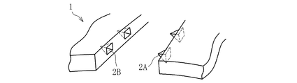
Abstract
【課題】互いに突き合わされる両端面同士の位置ずれを防止して、位置決め精度を向上させることができる管状部品を提供する。
【解決手段】本発明は、板状部材の互いに反対側に位置する両端面が突き合わされて管状に成形された管状部品であって、前記突き合わされた両端面を厚さ方向又は長さ方向あるいはそれら両方向に位置決めするために互いに係合する位置決め係合部2A,2Bが、前記両端面に設けられている。
【選択図】図2Provided is a tubular part that can prevent the positional deviation between both end faces that face each other and improve the positioning accuracy.
The present invention relates to a tubular part which is formed into a tubular shape by abutting both end faces located on opposite sides of a plate-like member, and the abutted both end faces are arranged in a thickness direction or a length direction or Positioning engagement portions 2A and 2B that engage with each other to position in both directions are provided on the both end faces.
[Selection] Figure 2
Description
本発明は、板状部材を管状に成形した管状部品、及びその管状部品の成形方法に関する。 The present invention relates to a tubular part obtained by forming a plate-like member into a tubular shape, and a method for forming the tubular part.
板状部材を管状に成形する方法として、例えば、プレス金型によって板状部材をU字形に曲げ加工した後、その成形品をO字形等の管状に曲げ加工する、いわゆるUO曲げ成形方法が知られている(下記特許文献1参照)。
As a method for forming a plate-like member into a tubular shape, for example, a so-called UO bending method is known in which a plate-like member is bent into a U shape using a press die, and then the formed product is bent into a tubular shape such as an O-shape. (See
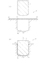
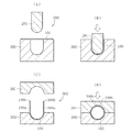
一般的に、斯かる成形方法では、まず、図22(A)(B)に示すように、平板状の金属板100をプレス金型200にセットし、上型201と下型202で金属板100をプレスすることによりU字形に曲げ加工する。次いで、図22(C)(D)に示すように、U字形に成形された成形品(金属板100)を別のプレス金型300にセットし、上型301と下型302でプレスすることにより、U字成形品の一対の縦壁部100aを曲げ、その各端部100bを互いに突き合わせるようにしてO字形等の管状部品を成形する。
Generally, in such a forming method, first, as shown in FIGS. 22A and 22B, a
ところで、上記のような管状部品は、断面形状が長さ方向に渡って変化するものや、長さ方向に対して直交する一方向に曲げられた二次元曲げ成形品、さらに、長さ方向に対して直交する二方向に曲げられた三次元曲げ成形品など、用途に応じて多種多様な形状のものが提案されている。 By the way, the tubular parts as described above include cross-sectional shapes that change in the length direction, two-dimensional bending molded products that are bent in one direction orthogonal to the length direction, and further in the length direction. A variety of shapes have been proposed depending on the application, such as a three-dimensional bent product bent in two directions perpendicular to each other.
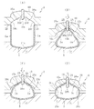
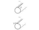
しかしながら、形状が複雑化すると、管状部品の左右の曲げ度合いに偏差が生じるなどにより、管状部品の互いに突き合わされる両端面の位置が、厚さ方向にずれる場合や{図23(A):厚さ方向のずれα参照}、長さ方向にずれる場合がある{図23(B):長さ方向のずれβ参照}。このようなずれの発生は、その後に行う溶接などの品質低下につながるため、両端面間の段差を無くすなどの追加工程が必要であった。 However, when the shape is complicated, the positions of both end surfaces of the tubular component that are brought into contact with each other may be shifted in the thickness direction due to deviations in the bending degree of the left and right of the tubular component, or {FIG. 23A: Thickness May be shifted in the length direction {FIG. 23B: refer to the shift β in the length direction}. The occurrence of such a shift leads to a deterioration in quality such as welding performed thereafter, and therefore an additional process such as eliminating a step between both end faces is necessary.
そこで、本発明は、管状部品の互いに突き合わされる両端面同士の位置ずれを防止することを目的とする。 Then, an object of this invention is to prevent the position shift of the both end surfaces where a tubular component is faced | matched mutually.
上記課題を解決するため、本発明は、板状部材の互いに反対側に位置する両端面が突き合わされて管状に成形された管状部品であって、前記突き合わされた両端面を厚さ方向又は長さ方向あるいはそれら両方向に位置決めするために互いに係合する位置決め係合部が、前記両端面に設けられている管状部品を提供する。 In order to solve the above-described problems, the present invention provides a tubular component formed into a tubular shape by abutting both end surfaces located on opposite sides of a plate-like member, wherein the abutted both end surfaces are formed in a thickness direction or a length. Provided is a tubular component in which positioning engaging portions that engage with each other for positioning in the lateral direction or both directions are provided on the both end faces.
なお、前記「突き合わされた両端面」には、両端面が互いに接触した状態となっている場合のほか、両端面同士の間に隙間があって互いに接近しない状態(非接触状態)となっている場合も含む。 In addition to the case where the both end surfaces are in contact with each other, the “abutted both end surfaces” are in a state where there is a gap between the both end surfaces and do not approach each other (non-contact state). This includes cases where
上記のように、位置決め係合部同士が係合することにより、互いに突き合わされた両端面を厚さ方向又は長さ方向あるいはそれら両方向に位置決めすることができるので、両端面間の位置ずれを防止することができ、位置合わせ精度を向上させることができる。 As described above, the positioning engagement portions engage with each other, so that both end faces that are abutted with each other can be positioned in the thickness direction or the length direction, or in both directions, thus preventing misalignment between both end faces. It is possible to improve the alignment accuracy.
また、上記課題を解決するため、本発明は、プレス金型によって板状部材を曲げ加工すると共に、前記板状部材の互いに反対側に位置する両端面を突き合わせて管状部品を成形する成形方法であって、前記板状部材を曲げ加工して前記両端面を互いに突き合わせる際に、前記両端面に設けられた位置決め係合部同士を係合させて、前記両端面を厚さ方向又は長さ方向あるいはそれら両方向に位置決めする管状部品の成形方法を提供する。 Further, in order to solve the above-mentioned problems, the present invention is a molding method in which a plate-shaped member is bent by a press mold and a tubular part is molded by abutting both end surfaces located on opposite sides of the plate-shaped member. When the plate-like member is bent and the both end faces are brought into contact with each other, the positioning engagement portions provided on the both end faces are engaged with each other so that the both end faces are in the thickness direction or length. A method of forming a tubular part that is positioned in one or both directions is provided.
このように、板状部材の両端面を互いに突き合わせる際に、両端面に設けられた位置決め係合部同士を係合させることで、両端面を厚さ方向又は長さ方向あるいはそれら両方向に位置決めすることができる。 As described above, when the both end surfaces of the plate-shaped member are brought into contact with each other, the positioning engagement portions provided on the both end surfaces are engaged with each other, thereby positioning the both end surfaces in the thickness direction or the length direction or in both these directions. can do.
さらに、前記板状部材を曲げ加工する際に、前記位置決め係合部をそれぞれ前記プレス金型に突き当てて、前記両端面の長さ方向の位置ずれを補正してもよい。 Furthermore, when bending the plate-shaped member, the positioning engagement portions may be brought into contact with the press molds to correct the positional deviation in the length direction of the both end faces.
このように、板状部材の曲げ加工時にプレス金型に対する突き当てにより位置ずれを補正することで、その後の位置決め係合部同士の係合をより確実に行えるようになり、位置合わせ精度が一層向上する。 In this way, by correcting the displacement by abutting against the press die during bending of the plate-like member, the subsequent positioning engagement portions can be more reliably engaged with each other, and the alignment accuracy is further increased. improves.
本発明によれば、管状部品の互いに突き合わされる両端面同士の位置ずれを防止して、両端面間の位置合わせ精度を向上させることができる。 ADVANTAGE OF THE INVENTION According to this invention, the position shift of the both end surfaces where a tubular component is mutually faced can be prevented, and the alignment precision between both end surfaces can be improved.
以下、添付の図面に基づき本発明の実施の形態について説明する。 Hereinafter, embodiments of the present invention will be described with reference to the accompanying drawings.
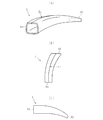
図1に、本発明の一実施形態に係る管状部品を示す。図1において、(A)は管状部品の斜視図、(B)は管状部品を上方から見た平面図、(C)は管状部品を横方向から見た側面図である。 FIG. 1 shows a tubular part according to an embodiment of the present invention. 1A is a perspective view of a tubular component, FIG. 1B is a plan view of the tubular component viewed from above, and FIG. 1C is a side view of the tubular component viewed from the lateral direction.
図1に示す管状部品1は、1枚の金属製の板状部材を曲げ加工して、板状部材の互いに反対側に位置する両端面を対向するように突き合わせて成形されている。従って、管状部品1には、その長さ方向に渡って板状部材の両端面同士が突き合わされた線状の突き合わせ部1cが形成されている。図1では、突き合わされた両端面同士が互いに接触した状態となっているが、両端面同士の間に隙間があって互いに接近しない状態(非接触状態)となっている場合であってもよい。また、管状部品1は、その長さ方向の一端部1aから他端部1bに向かって略正方形の断面形状から扁平な略長方形の断面形状へと変化するように形成されている。さらに、管状部品1は、長さ方向に渡ってこれと直交する二方向(縦方向と横方向)に曲げられた三次元曲げ形状に成形されている。
The
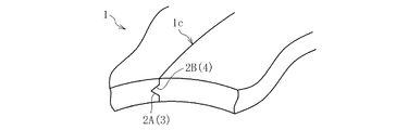
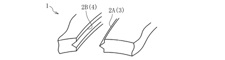
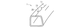
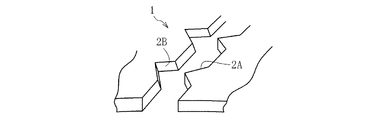
図2は、本実施形態に係る管状部品の突き合わせ部の拡大図、図3は、突き合わせ部を分離した状態を示す拡大図である。 FIG. 2 is an enlarged view of the butted portion of the tubular part according to the present embodiment, and FIG. 3 is an enlarged view showing a state where the butted portion is separated.
図2及び図3に示すように、本実施形態に係る管状部品1においては、互いに突き合わされた両端面(以下、「合わせ面」という。)に、互いに係合する位置決め係合部2A,2Bが設けられている。図3に示すように、一方の合わせ面に設けられた位置決め係合部2Aは、長さ方向に渡って連続する三角形状の凸部3で構成され、他方の合わせ面に設けられた位置決め係合部2Bは、長さ方向に渡って連続する三角形状の凹部4で構成されている。
As shown in FIGS. 2 and 3, in the
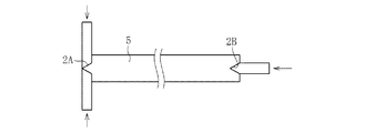
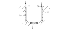
各位置決め係合部2A,2Bの形成は、例えば、板状部材が管状に成形される前の平板材(ブランク材)の段階で行うことができる。具体的には、図4に示すように、板状部材5の一端部(一方の合わせ面)を工具又はプレス機等で上下方向から挟んで潰すことで凸状の位置決め係合部2Aを形成し、板状部材5の反対側の端面(他方の合わせ面)に先の尖ったパンチ等を押し当てることで凹状の位置決め係合部2Bを形成することができる。
Each
続いて、本実施形態に係る管状部品の成形方法及びその成形に用いる金型装置(プレス金型)について説明する。
ここで、本実施形態に係る管状部品は長さ方向に渡って断面形状が異なっているが、各断面における曲げ変形の挙動については基本的に同様であるので、一部の断面における曲げ変形を例に説明する。
Subsequently, a method for molding a tubular part according to the present embodiment and a mold apparatus (press mold) used for the molding will be described.
Here, the tubular parts according to the present embodiment have different cross-sectional shapes in the length direction, but the behavior of bending deformation in each cross section is basically the same, so that bending deformation in some cross sections is performed. Explained as an example.
まず、図5に示すU曲げ金型装置6を用いて、板状部材5(ブランク材)をU字形に成形するU曲げ工程を行う。なお、この時点で、板状部材5の両合わせ面には、予め位置決め係合部2A,2Bが形成されている。U曲げ金型装置6は、昇降可能な上型7と、固定された下型8とを備えている。下型8には、U字形の凹部8aが形成されている。
First, the U-bending process which shape | molds the plate-shaped member 5 (blank material) in a U shape using the U-bending die apparatus 6 shown in FIG. 5 is performed. At this time,
U曲げ工程では、下型8の上に板状部材5がセットされた状態で{図5(A)参照}、上型7を降下させる{図5(B)参照}。これにより、板状部材5が上型7と下型8とでプレスされて、断面略U字形のU字成形品が得られる。
In the U-bending step, the plate-shaped
次に、図6に示す中間曲げ金型装置9を用いて、U字成形品を所定の中間曲げ成形品に成形する中間曲げ工程を行う。中間曲げ金型装置9は、昇降可能な上型10と、固定された下型11とを備える。上型10は、上方に向かって互いに接近する方向に傾斜した一対の傾斜面10aと、一対の傾斜面10aの上端の間から下方に突出した係止部10bと、一対の傾斜面10aの下端から下方に滑らかに連続する成形面10cとを有する。係止部10bは、各傾斜面10aの上端から下方に延びる係止面10dを有する。本実施形態では、係止部10bが上型10の本体部と別体で構成されているが、一体に構成されていてもよい。下型11には、U字形に成形された板状部材5の曲げ部(底部)と同形状の凹部11aが形成されている。
Next, using the intermediate bending die apparatus 9 shown in FIG. 6, an intermediate bending process for forming a U-shaped product into a predetermined intermediate bending product is performed. The intermediate bending mold apparatus 9 includes an
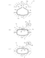
中間曲げ工程では、まず、図6(A)に示すように、下型11の凹部11aに上記断面略U字形に成形された板状部材5(U字成形品)をセットする。そして、図6(B)に示すように、上型10を降下させる。このとき、板状部材5の一対の縦壁部5aの各端部(両合わせ面)が上型10の傾斜面10aに沿ってガイドされることで、一対の縦壁部5aが内側に傾斜して、両合わせ面が上型10の係止部10b(一対の係止面10d)に突き当たる。そして、図6(C)に示すように、さらに上型10を降下させると、一対の縦壁部5aに対して長さ方向に圧縮荷重が作用することで座屈が生じ、各縦壁部5aの中間部が外側へ膨出する。そして、図5(D)に示すように、さらに上型10を降下させると、各縦壁部5aの膨出する部分が上型10の成形面10cに押し付けられ、各縦壁部5aの中間部に中間曲げ部5bが成形される。このようにして、中間成形品が成形される。
In the intermediate bending step, first, as shown in FIG. 6 (A), the plate-like member 5 (U-shaped product) formed in the substantially U-shaped cross section is set in the concave portion 11a of the
最後に、図7に示す最終曲げ金型装置12を用いて、上記中間成形品を管状に成形する最終曲げ工程を行う。最終曲げ金型装置12は、昇降可能な上型13と、固定された下型14とを備える。上型13と下型14には、それぞれ凹部13a,14aが形成されている。
Finally, a final bending step of forming the intermediate molded product into a tubular shape is performed using the final bending die
最終曲げ工程では、まず、図7(A)に示すように、下型14の凹部14aに上記中間曲げ形状に成形された板状部材5(中間成形品)をセットする。そして、図7(B)に示すように、上型10を降下させることで、各縦壁部5aの中間曲げ部5bがさらに曲げられる。その後、図7(C)に示すように、さらに上型10を降下させて型締めすることで、板状部材5の合わせ面同士が突き合わされ、板状部材5が外側に張り出して上型13及び下型14に押し付けられる。その結果、所望の断面形状を有する管状部品が成形される。
In the final bending step, first, as shown in FIG. 7A, the plate-like member 5 (intermediate molded product) molded in the intermediate bending shape is set in the
ここで、図7(B)(C)の拡大図に示すように、板状部材5の合わせ面同士が互いに突き合わされる際、各合わせ面に設けられた位置決め係合部2A,2B同士が互いに係合する。このように、位置決め係合部2A,AB同士が互いに係合することで、合わせ面の厚さ方向の位置ずれが防止される。特に、本実施形態のように、三次元曲げ形状に成形された管状部品においては、突き合わせ部1c(図1参照)を境界として左側の部分と右側の部分とでは曲がり方が異なるため、曲り度合いに左右偏差が生じる。その結果、管状部品を金型から取り出した際に、スプリングバックによって合わせ面が厚さ方向にずれる場合がある{図23(A)参照}。しかしながら、本実施形態に係る管状部品においては、位置決め係合部同士が係合することで、厚さ方向の位置ずれを防止することができ、合わせ面同士の位置合わせ精度が向上する。これにより、合わせ面間の段差を無くす追加処理を行わなくても、合わせ面同士の溶接を良好に行うことができ、製造工数やコストを削減できるようになる。
Here, as shown in the enlarged views of FIGS. 7B and 7C, when the mating surfaces of the plate-
また、本実施形態おいては、各位置決め係合部が三角形状に形成されていることで、これらが合わせ面同士の位置ずれを補正するガイド部として機能することができる。すなわち、図8に示すように、長さ方向に対して直交する断面方向から見て、各位置決め係合部2A,2Bが突き合わせ方向X1,X2に対して傾斜する傾斜面2a1,2b1を有することで、合わせ面同士が突き合わされる際に、各位置決め係合部2A,2Bの傾斜面2a1,2b1同士が接触することにより、合わせ面が所望の位置に誘導され、厚さ方向の位置ずれを補正することができる。これにより、板状部材を曲げ加工する際に合わせ面同士の間で厚さ方向のずれが生じたとしても、そのずれを補正し、位置決め係合部同士を確実に係合させることができる。
Moreover, in this embodiment, since each positioning engaging part is formed in the triangle shape, these can function as a guide part which correct | amends the position shift of a mating surface. That is, as shown in FIG. 8, each
しかも、本実施形態においては、各位置決め係合部が、それぞれ互いに異なる方向を向く2つの傾斜面を有しているので、合わせ面同士の位置ずれが厚さ方向の一方又は反対方向のいずれの方向に生じたとしても、その位置ずれを補正することができる。また、位置ずれ方向が一方向に決まっている場合は、図9に示す例のように、各位置決め係合部2A,2Bが、それぞれ1つの傾斜面2a1,2b1を有するようにしてもよい。
Moreover, in the present embodiment, each positioning engagement portion has two inclined surfaces that face in different directions, so that the misalignment between the mating surfaces is either in the thickness direction or in the opposite direction. Even if it occurs in the direction, the positional deviation can be corrected. Further, when the positional deviation direction is determined in one direction, each
また、位置決め係合部の形状は、三角形状に限らず、図10に示すような半円形等の曲線状の凸部及び凹部から成る位置決め係合部2A,2Bであってもよい。また、上記傾斜面によるガイド機能が不要な場合は、図11に示すような、四角形状の凸部及び凹部から成る位置決め係合部2A,2Bであってもよい。
In addition, the shape of the positioning engagement portion is not limited to a triangular shape, and may be positioning
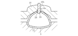
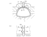
上述の成形方法では、位置決め係合部の形成タイミングをブランク材の段階で行っているが、管状部品の成形工程の途中で行ってもよい。例えば、図12に示すように、U字成形品を成形した段階で、そのU字成形品一対の縦壁部5aの先端面(合わせ面)に工具等を押し当てることで位置決め係合部2A,2Bを形成してもよい。また、図13に示すように、中間曲げ成形用の金型(図の例では、上型10の係止部10b)に突起10eを設けておき、中間曲げ工程時に、各突起10eに板状部材5の両合わせ面が押し当てられることで、位置決め係合部2A,2Bが形成されるようにしてもよい。
In the molding method described above, the positioning engagement portion is formed at the blank material stage, but may be performed during the tubular component molding process. For example, as shown in FIG. 12, at the stage where a U-shaped molded product is formed, the
図14及び図15に、本発明の他の実施形態に係る管状部品を示す。 14 and 15 show a tubular part according to another embodiment of the present invention.
図14及び図15に示す管状部品1は、上記図1及び図2等に示す管状部品と比べて、位置決め係合部2A,2Bの構成が異なっている。それ以外は、同様の構成である。具体的に、図14及び図15に示す本実施形態においては、各位置決め係合部2A,2Bが管状部品1の上方から見て三角形状に形成されている。すなわち、本実施形態では、各位置決め係合部2A,2Bが、合わせ面の稜線を長さ方向に渡って三角形状に変化させて形成されているのに対して、上記図1及び図2等に示す実施形態では、各位置決め係合部2A,2Bが、合わせ面の稜線を厚さ方向に渡って三角形状に変化させて形成されている点において異なっている。図14及び図15に示す本実施形態では、各位置決め係合部2A,2Bが、長さ方向に渡って断続的に設けられているが、長さ方向に連続して並ぶように設けられていてもよい。
The
このような位置決め係合部が設けられていることで、位置決め係合部同士を係合させることにより、合わせ面同士の長さ方向の位置ずれを防止することができる。特に、本実施形態のように、三次元曲げ形状に形成された管状部品においては、曲り度合いに左右偏差が生じることで、合わせ面間で長さ方向のずれ{図23(B)参照}が生じやすい傾向にある。そこで、図14及び図15に示すような位置決め係合部2A,2Bを形成し、合わせ面同士を突き合わせる際に、位置決め係合部2A,2Bを互いに係合させることで、合わせ面間の長さ方向の位置ずれを防止できるようになる。なお、本実施形態における管状部品の成形方法や成形用金型は、上記実施形態に係る方法及び金型と基本的に同様であるので説明を省略する。また、板状部材に位置決め係合部を形成するタイミングは、ブランク材の段階で行ってもよいし、管状部品の成形工程の途中で行ってもよい。
By providing such a positioning engagement portion, it is possible to prevent the displacement of the mating surfaces in the length direction by engaging the positioning engagement portions. In particular, in a tubular part formed in a three-dimensional bent shape as in this embodiment, a deviation in the length direction between the mating surfaces {see FIG. 23B} occurs due to a lateral deviation in the degree of bending. It tends to occur. Accordingly, the
また、本実施形態においても、各位置決め係合部が三角形状に形成されていることで、位置決め係合部が合わせ面同士の位置ずれを補正するガイド部として機能することができる。すなわち、図16に示すように、上方から見て、各位置決め係合部2A,2Bが突き合わせ方向X1,X2に対して傾斜する傾斜面2a1,2b1を有しているため、合わせ面同士が突き合わされる際に、各位置決め係合部2A,2Bの傾斜面2a1,2b1同士が接触することにより、合わせ面が所望の位置に誘導され、長さ方向の位置ずれを補正することができる。これにより、板状部材を曲げ加工する際に合わせ面同士の間で長さ方向のずれが生じたとしても、そのずれを補正し、位置決め係合部同士を確実に係合させることができる。
Also in the present embodiment, each positioning engagement portion is formed in a triangular shape, so that the positioning engagement portion can function as a guide portion that corrects the positional deviation between the mating surfaces. That is, as shown in FIG. 16, since the
さらに、本実施形態では、各位置決め係合部が、それぞれ互いに異なる方向を向く2つの傾斜面を有することで、合わせ面同士の位置ずれが長さ方向の一方又は反対方向のいずれの方向に生じたとしても、その位置ずれを補正することができる。また、位置ずれ方向が一方向に決まっている場合は、図17に示す例のように、各位置決め係合部2A,2Bが、それぞれ1つの傾斜面2a1,2b1を有するようにしてもよい。
Furthermore, in the present embodiment, each positioning engagement portion has two inclined surfaces that are directed in different directions, so that the misalignment between the mating surfaces occurs in one of the length directions or in the opposite direction. Even so, the positional deviation can be corrected. Further, when the positional deviation direction is determined in one direction, each
また、長さ方向の位置ずれ補正は、上記のような傾斜面2a1,2b1同士の接触による場合に限らず、傾斜面2a1,2b1を金型に接触させることによって行ってもよい。例えば、図18に示すように、中間曲げ成形用の上型10の係止部10b等に、突き当て方向X1,X2に対して傾斜するガイド面10f、10gを設けておき、中間曲げ工程時に、各位置決め係合部2A,2Bの傾斜面2a1,2b1をガイド面10f,10gに突き当てることで、合わせ面同士の長さ方向の位置ずれを補正することができる。特に、長さ方向の位置ずれは、板状部材が大きく曲げ加工される段階で顕著に生じる傾向にあるので、図18に示す例のように、中間曲げ工程時に長さ方向の位置ずれを補正することで、その後の位置決め係合部2A,2B同士の係合をより確実に行えるようになり、位置合わせ精度が一層向上する。
Further, the positional deviation correction in the length direction is not limited to the case where the inclined surfaces 2a1, 2b1 are in contact with each other as described above, but may be performed by bringing the inclined surfaces 2a1, 2b1 into contact with the mold. For example, as shown in FIG. 18, guide surfaces 10 f and 10 g that are inclined with respect to the abutting directions X <b> 1 and X <b> 2 are provided on the locking
また、本実施形態においても、位置決め係合部の形状は、三角形状に限らない。例えば、図19に示すような半円形等の曲線状、あるいは、図20に示すような、四角形状であってもよい。 Also in this embodiment, the shape of the positioning engagement portion is not limited to a triangular shape. For example, a curved shape such as a semicircular shape as shown in FIG. 19 or a rectangular shape as shown in FIG.
上述の各実施形態では、位置決め係合部によって厚さ方向と長さ方向のいずれか一方の位置決めを行う構成について説明したが、図21に示す実施形態のように、位置決め係合部2A,2Bを四角錐状の凸部及び凹部で構成することで、厚さ方向と長さ方向の両方向の位置決めを行うことが可能である。また、位置決め係合部を三角錐状や円錐状等に形成してもよい。要するに、合わせ面の稜線を厚さ方向と長さ方向の両方向に渡って変化させて位置決め係合部2A,2Bを形成すればよい。また、この場合、各位置決め係合部2A,2Bに設けられた4つの傾斜面が位置ずれを補正するガイド面として機能することで、厚さ方向と長さ方向の両方向の位置ずれを補正することができる。なお、傾斜面によるガイド機能が不要な場合は、位置決め係合部を四角柱状又は三角柱状あるいは円柱状等の形状に形成してもよい。
In each of the above-described embodiments, the configuration in which one of the thickness direction and the length direction is positioned by the positioning engagement portion has been described. However, as in the embodiment shown in FIG. 21, the
以上、本発明の各実施形態について説明したように、管状部品の両合わせ面に互いに係合する位置決め係合部を設けることで、合わせ面同士の位置ずれを防止でき、その位置合わせ精度を向上させることができる。特に、長さ方向に渡って断面形状が変化するのに加えて、三次元曲げ形状に形成された管状部品においては、合わせ面同士の位置ずれが厚さ方向又は長さ方向に生じやすい傾向にあるので、本発明に係る構成や成形方法を適用することで大きな効果を期待できる。例えば、自動車のリアサスペンションの左右のトレーリングアームやこれらを連結する中間ビーム等の管状部品に本発明を適用することが可能である。なお、位置決め係合部は、実験あるいはシミュレーションによって特定された位置ずれ箇所のみに少なくとも設けられていればよい。 As described above with respect to the embodiments of the present invention, by providing the positioning engagement portions that engage with each other on the mating surfaces of the tubular parts, the misalignment between the mating surfaces can be prevented, and the alignment accuracy is improved. Can be made. In particular, in addition to the change in cross-sectional shape over the length direction, in tubular parts formed in a three-dimensional bending shape, the misalignment between the mating surfaces tends to occur easily in the thickness direction or the length direction. Therefore, a great effect can be expected by applying the configuration and the molding method according to the present invention. For example, the present invention can be applied to tubular parts such as left and right trailing arms of a rear suspension of an automobile and an intermediate beam connecting them. In addition, the positioning engagement part should just be provided only in the position shift location specified by experiment or simulation.
また、本発明は、このような管状部品に限らず、長さ方向に渡って断面形状が変化しない管状部品や、長さ方向に渡って曲げられないストレート状の管状部品に対しても適用可能である。斯かる構成の管状部品においても、材料強度のばらつきなどにより合わせ面の位置ずれが生じる可能性があるので、本発明を適用することにより一定の効果が期待される。 Further, the present invention is not limited to such a tubular part, but can be applied to a tubular part whose cross-sectional shape does not change in the length direction and a straight tubular part that is not bent in the length direction. It is. Even in a tubular part having such a configuration, the misalignment of the mating surfaces may occur due to variations in material strength, etc., so that a certain effect is expected by applying the present invention.
1 管状部品
2A 位置決め係合部
2B 位置決め係合部
2a1 傾斜面
2b1 傾斜面
5 板状部材
6 U曲げ金型装置
9 中間曲げ金型装置
12 最終曲げ金型装置
DESCRIPTION OF
Claims (2)
前記突き合わされた両端面を厚さ方向又は長さ方向あるいはそれら両方向に位置決めするために互いに係合する位置決め係合部が、前記両端面に設けられていることを特徴とする管状部品。 Tubular parts formed into a tubular shape by butting both end faces located on opposite sides of the plate-shaped member,
A tubular part characterized in that positioning end portions that engage with each other in order to position the abutted both end surfaces in the thickness direction or the length direction or in both directions are provided on the both end surfaces.
前記板状部材を曲げ加工して前記両端面を互いに突き合わせる際に、前記両端面に設けられた位置決め係合部同士を係合させて、前記両端面を厚さ方向又は長さ方向あるいはそれら両方向に位置決めすることを特徴とする管状部品の成形方法。 A molding method for bending a plate-like member by a press die and molding a tubular part by abutting both end faces located on opposite sides of the plate-like member,
When bending the plate-shaped member and abutting the both end surfaces with each other, the positioning engagement portions provided on the both end surfaces are engaged with each other so that the both end surfaces are in the thickness direction or the length direction or those A method for forming a tubular part, characterized by positioning in both directions.
Priority Applications (1)
| Application Number | Priority Date | Filing Date | Title |
|---|---|---|---|
| JP2017163353A JP6995430B2 (en) | 2017-08-28 | 2017-08-28 | Molding method for mold equipment and tubular parts |
Applications Claiming Priority (1)
| Application Number | Priority Date | Filing Date | Title |
|---|---|---|---|
| JP2017163353A JP6995430B2 (en) | 2017-08-28 | 2017-08-28 | Molding method for mold equipment and tubular parts |
Publications (2)
| Publication Number | Publication Date |
|---|---|
| JP2019038024A true JP2019038024A (en) | 2019-03-14 |
| JP6995430B2 JP6995430B2 (en) | 2022-01-14 |
Family
ID=65726026
Family Applications (1)
| Application Number | Title | Priority Date | Filing Date |
|---|---|---|---|
| JP2017163353A Active JP6995430B2 (en) | 2017-08-28 | 2017-08-28 | Molding method for mold equipment and tubular parts |
Country Status (1)
| Country | Link |
|---|---|
| JP (1) | JP6995430B2 (en) |
Cited By (3)
| Publication number | Priority date | Publication date | Assignee | Title |
|---|---|---|---|---|
| JP2022019419A (en) * | 2020-07-17 | 2022-01-27 | 三井金属計測機工株式会社 | Strip-shaped member connector and strip-shaped member connection jig |
| CN114643301A (en) * | 2020-12-17 | 2022-06-21 | 佳能株式会社 | Methods, punches, manufacturing systems, apparatus and products for making products |
| EP4137242A1 (en) * | 2021-08-18 | 2023-02-22 | Wasserthal, Yevheniya | Method for manufacturing a tubular body, in particular a holding rod, and a holding rod obtained using such a method |
Citations (4)
| Publication number | Priority date | Publication date | Assignee | Title |
|---|---|---|---|---|
| JPH05164491A (en) * | 1991-12-13 | 1993-06-29 | Nippondenso Co Ltd | Heat exchange tube and method of manufacturing the same |
| JPH09234511A (en) * | 1996-02-29 | 1997-09-09 | Nikki Kogyo Kk | Method and device for manufacturing metal wound pipe |
| JP2001259733A (en) * | 2000-03-16 | 2001-09-25 | Mitsubishi Shindoh Co Ltd | Apparatus and method for manufacturing ERW pipe |
| JP2011136833A (en) * | 2010-01-04 | 2011-07-14 | Seiko Epson Corp | Method of manufacturing carrier roller, carrier roller, carrying unit, and printer |
-
2017
- 2017-08-28 JP JP2017163353A patent/JP6995430B2/en active Active
Patent Citations (4)
| Publication number | Priority date | Publication date | Assignee | Title |
|---|---|---|---|---|
| JPH05164491A (en) * | 1991-12-13 | 1993-06-29 | Nippondenso Co Ltd | Heat exchange tube and method of manufacturing the same |
| JPH09234511A (en) * | 1996-02-29 | 1997-09-09 | Nikki Kogyo Kk | Method and device for manufacturing metal wound pipe |
| JP2001259733A (en) * | 2000-03-16 | 2001-09-25 | Mitsubishi Shindoh Co Ltd | Apparatus and method for manufacturing ERW pipe |
| JP2011136833A (en) * | 2010-01-04 | 2011-07-14 | Seiko Epson Corp | Method of manufacturing carrier roller, carrier roller, carrying unit, and printer |
Cited By (5)
| Publication number | Priority date | Publication date | Assignee | Title |
|---|---|---|---|---|
| JP2022019419A (en) * | 2020-07-17 | 2022-01-27 | 三井金属計測機工株式会社 | Strip-shaped member connector and strip-shaped member connection jig |
| JP7448435B2 (en) | 2020-07-17 | 2024-03-12 | 三井金属計測機工株式会社 | Strip-like member connection body and jig for connecting strip-like members |
| CN114643301A (en) * | 2020-12-17 | 2022-06-21 | 佳能株式会社 | Methods, punches, manufacturing systems, apparatus and products for making products |
| US12162060B2 (en) | 2020-12-17 | 2024-12-10 | Canon Kabushiki Kaisha | Method for manufacturing product, punch, manufacturing system, device, and product |
| EP4137242A1 (en) * | 2021-08-18 | 2023-02-22 | Wasserthal, Yevheniya | Method for manufacturing a tubular body, in particular a holding rod, and a holding rod obtained using such a method |
Also Published As
| Publication number | Publication date |
|---|---|
| JP6995430B2 (en) | 2022-01-14 |
Similar Documents
| Publication | Publication Date | Title |
|---|---|---|
| US7318455B2 (en) | Pipe body and forming method of the same | |
| EP2906373B1 (en) | Hollow rack bar and method of manufacturing hollow rack bar | |
| EP3406364B1 (en) | Method for manufacturing press-molded article, and press apparatus | |
| JP7110186B2 (en) | CYLINDRICAL BODY AND METHOD FOR MANUFACTURING CYLINDRICAL BODY | |
| KR101642630B1 (en) | Method and apparatus for forming closed cross-sectional structure | |
| US6591576B1 (en) | Structural member having closed sections, and apparatus and method for producing the structural member | |
| KR20150006065A (en) | Method for manufacturing tube shaped part with different diameters and forming mold | |
| JP2006289496A (en) | Cylindrical shaft and its manufacturing method | |
| JP6995430B2 (en) | Molding method for mold equipment and tubular parts | |
| CN105324194B (en) | Manufacturing press-molded products and its manufacture method | |
| JP2021010948A (en) | Burring method, method of manufacturing burred component, and burring device | |
| KR100224930B1 (en) | Method for producing pipe having polygon-shaped cross-section and device therefor | |
| KR101824341B1 (en) | Method for producing polygonal closed cross-section structural component with a curved form and polygonal closed cross-section structural component produced by this method | |
| US20240217289A1 (en) | Method for manufacturing vehicle suspension arm and vehicle suspension arm | |
| JP2734818B2 (en) | Mold for flange forming | |
| JP2015167962A (en) | Bending method of plate workpiece and die as well as bending product | |
| KR102098022B1 (en) | Torsion beam and manuacturing method for torsion beam | |
| CN113245395B (en) | Method for manufacturing tube | |
| US12337898B2 (en) | Body frame member and method for manufacturing body frame member | |
| JP7244192B2 (en) | Cylindrical part and manufacturing method thereof | |
| JP2016155167A (en) | Processing method of square columnar-body pipe | |
| JP7054295B2 (en) | Press molding method for tubular parts and O-bending die used for this | |
| CN101175583B (en) | Cylindrical shaft and manufacturing method thereof | |
| JP2007501714A (en) | Metal pipe press forming method | |
| CN110314975B (en) | Punch structure of stamping die, stamping die, manufacturing method of stamping forming part and stamping forming part |
Legal Events
| Date | Code | Title | Description |
|---|---|---|---|
| A621 | Written request for application examination |
Free format text: JAPANESE INTERMEDIATE CODE: A621 Effective date: 20200513 |
|
| A131 | Notification of reasons for refusal |
Free format text: JAPANESE INTERMEDIATE CODE: A131 Effective date: 20210419 |
|
| A521 | Request for written amendment filed |
Free format text: JAPANESE INTERMEDIATE CODE: A523 Effective date: 20210513 |
|
| A131 | Notification of reasons for refusal |
Free format text: JAPANESE INTERMEDIATE CODE: A131 Effective date: 20211025 |
|
| A521 | Request for written amendment filed |
Free format text: JAPANESE INTERMEDIATE CODE: A523 Effective date: 20211117 |
|
| TRDD | Decision of grant or rejection written | ||
| A01 | Written decision to grant a patent or to grant a registration (utility model) |
Free format text: JAPANESE INTERMEDIATE CODE: A01 Effective date: 20211214 |
|
| A61 | First payment of annual fees (during grant procedure) |
Free format text: JAPANESE INTERMEDIATE CODE: A61 Effective date: 20211214 |
|
| R150 | Certificate of patent or registration of utility model |
Ref document number: 6995430 Country of ref document: JP Free format text: JAPANESE INTERMEDIATE CODE: R150 |
|
| R250 | Receipt of annual fees |
Free format text: JAPANESE INTERMEDIATE CODE: R250 |
|
| R250 | Receipt of annual fees |
Free format text: JAPANESE INTERMEDIATE CODE: R250 |