JP2019043295A - Sunroof device - Google Patents
Sunroof device Download PDFInfo
- Publication number
- JP2019043295A JP2019043295A JP2017166967A JP2017166967A JP2019043295A JP 2019043295 A JP2019043295 A JP 2019043295A JP 2017166967 A JP2017166967 A JP 2017166967A JP 2017166967 A JP2017166967 A JP 2017166967A JP 2019043295 A JP2019043295 A JP 2019043295A
- Authority
- JP
- Japan
- Prior art keywords
- notch
- guide rail
- vehicle
- frame
- longitudinal direction
- Prior art date
- Legal status (The legal status is an assumption and is not a legal conclusion. Google has not performed a legal analysis and makes no representation as to the accuracy of the status listed.)
- Pending
Links
Images




Landscapes
- Window Of Vehicle (AREA)
Abstract
Description
この発明は、サンルーフ装置に関する。 The present invention relates to a sunroof device.
従来、車両のルーフ開口部に設けられるサンルーフ装置が知られている。例えば、特許文献1には、ルーフ開口部の両縁に配置されて車両前後方向に延在するサイドレールと、ルーフ開口部の前縁に配置されたフロントフレームと、サイドレールにスライド自在に支持されたスライドパネル(可動パネル)とを備えたサンルーフ装置が開示されている。このサンルーフ装置では、サイドレールの端部とフロントフレームの端部とがリベットにより連結されている。 BACKGROUND Conventionally, a sunroof device provided at a roof opening of a vehicle is known. For example, in Patent Document 1, side rails disposed at both edges of the roof opening and extending in the vehicle longitudinal direction, a front frame disposed at the front edge of the roof opening, and a side rail slidably supported Discloses a sunroof apparatus provided with a slide panel (movable panel). In this sunroof device, the end of the side rail and the end of the front frame are connected by rivets.
しかしながら、特許文献1のサンルーフ装置では、サイドレール(ガイドレール)の端部とフロントフレームの端部とを連結するためにリベットが必要となるので、部品点数を削減することが困難である。 However, in the sunroof device of Patent Document 1, it is difficult to reduce the number of parts because a rivet is required to connect the end of the side rail (guide rail) and the end of the front frame.
そこで、この発明は、部品点数を削減することが可能なサンルーフ装置を提供することを目的とする。 Then, this invention aims at providing the sunroof apparatus which can reduce a number of parts.
第1の発明は、車両のルーフ開口部(2)に設けられるサンルーフ装置を対象とし、上記ルーフ開口部(2)の車幅方向の縁部に沿うように延びる一対のガイドレール(21)と、該ルーフ開口部(2)の車両前後方向の縁部に配置される第1フレーム(22)とを有するフレームアセンブリ(20)と、上記一対のガイドレール(21)により車両前後方向にスライド可能に支持される可動パネル(40)とを備え、上記第1フレーム(22)は、上記ルーフ開口部(2)の車両前後方向の縁部に沿うように延びるフレーム本体(23)と、該フレーム本体(23)の長手方向の端部から車両前後方向に延出して上記ガイドレール(21)の長手方向の一端部に重なるフレーム延出部(24)とを有し、上記ガイドレール(21)の長手方向の一端部には、該ガイドレール(21)の短手方向に開口する切り欠き部(81)が設けられ、上記フレーム延出部(24)には、上記ガイドレール(21)の切り欠き部(81)と係合するように構成された突起部(91)が設けられていることを特徴とする。 The first invention is directed to a sunroof device provided in a roof opening (2) of a vehicle, and a pair of guide rails (21) extending along the edge of the roof opening (2) in the vehicle width direction A frame assembly (20) having a first frame (22) disposed at an edge of the roof opening (2) in the vehicle longitudinal direction, and the pair of guide rails (21) being slidable in the vehicle longitudinal direction And a frame body (23) extending along the edge of the roof opening (2) in the longitudinal direction of the vehicle, and the frame A frame extension (24) extending from the longitudinal end of the main body (23) in the longitudinal direction of the vehicle and overlapping one end of the guide rail (21) in the longitudinal direction; At one longitudinal end of the guide rail (21) And the frame extension (24) is configured to be engaged with the notch (81) of the guide rail (21). A projection (91) is provided.
上記第1の発明では、フレーム延出部(24)の突起部(91)とガイドレール(21)の切り欠き部(81)とを係合させることにより、リベットを用いることなくガイドレール(21)の長手方向の一端部と第1フレーム(22)のフレーム延出部(24)とを接続することができる。これにより、リベットを用いることなくガイドレール(21)と第1フレーム(22)とを連結することができる。 In the first aspect of the invention, the guide rail (21) is used without using a rivet by engaging the projection (91) of the frame extension (24) with the notch (81) of the guide rail (21). And the frame extension (24) of the first frame (22) can be connected. Thereby, the guide rail (21) and the first frame (22) can be connected without using a rivet.
第2の発明は、上記第1の発明において、上記フレーム延出部(24)には、上記突起部(91)よりも該フレーム延出部(24)の基端側に配置されて上記ガイドレール(21)の長手方向の一端部と接触するように構成された壁部(90)が設けられていることを特徴とする。 According to a second aspect of the present invention, in the first aspect, the frame extension portion (24) is disposed on the proximal end side of the frame extension portion (24) than the projection portion (91), and the guide is It is characterized in that a wall (90) configured to be in contact with one longitudinal end of the rail (21) is provided.
上記第2の発明では、フレーム延出部(24)の壁部(90)とガイドレール(21)の長手方向の一端部とを接触させてフレーム延出部(24)の突起部(91)とガイドレール(21)の切り欠き部(81)とを係合させることにより、リベットを用いることなくガイドレール(21)の長手方向の一端部と第1フレーム(22)のフレーム延出部(24)とを堅固に接続することができる。これにより、リベットを用いることなくガイドレール(21)と第1フレーム(22)とを連結することができる。 In the second aspect of the invention, the projection (91) of the frame extension (24) is brought into contact with the wall (90) of the frame extension (24) and one end of the guide rail (21) in the longitudinal direction. And the notch portion (81) of the guide rail (21), the longitudinal end portion of the guide rail (21) and the frame extension portion of the first frame (22) without using a rivet 24) can be connected firmly. Thereby, the guide rail (21) and the first frame (22) can be connected without using a rivet.
第3の発明は、上記第1または第2の発明において、上記切り欠き部(81)および上記突起部(91)は、該切り欠き部(81)の奥側から開口側へ向かう該突起部(91)の移動が規制されるように構成されていることを特徴とする。 According to a third invention, in the first or second invention, the notch (81) and the protrusion (91) are a protrusion extending from the back side to the opening of the notch (81). It is characterized in that the movement of (91) is regulated.
上記第3の発明では、切り欠き部(81)の奥側から開口側へ向けて突起部(91)が移動して突起部(91)が切り欠き部(81)から抜け出すことを防止することができる。 In the third aspect of the invention, the projection (91) is moved from the back side of the notch (81) to the opening side to prevent the projection (91) from coming off the notch (81). Can.
第4の発明は、上記第3の発明において、上記切り欠き部(81)は、上記ガイドレール(21)の長手方向の他端側を向く第1縁部(81a)を有し、上記突起部(91)は、上記切り欠き部(81)の第1縁部(81a)と接触する第1側部(91a)を有し、上記切り欠き部(81)の第1縁部(81a)と上記突起部(91)の第1側部(91a)は、該切り欠き部(81)の開口側から奥側へ向けて上記ガイドレール(21)の長手方向の他端側から一端側に傾斜するように構成されていることを特徴とする。 In a fourth aspect based on the third aspect, the notch (81) has a first edge (81a) facing the other end side in the longitudinal direction of the guide rail (21), and the protrusion The portion (91) has a first side (91a) in contact with the first edge (81a) of the notch (81), and the first edge (81a) of the notch (81) And the first side portion (91a) of the projection (91) from the opening side of the notch (81) to the far side from the other end side of the guide rail (21) in the longitudinal direction to one end side It is characterized in that it is configured to be inclined.
上記第4の発明では、切り欠き部(81)の奥側から開口側へ向かう突起部(91)の移動を規制することができる。これにより、切り欠き部(81)の奥側から開口側へ向けて突起部(91)が移動して突起部(91)が切り欠き部(81)から抜け出すことを防止することができる。 In the fourth aspect of the invention, the movement of the projection (91) can be restricted from the back side of the notch (81) to the opening side. Thus, the protrusion (91) can be prevented from moving from the back side of the notch (81) to the opening side and the protrusion (91) being pulled out of the notch (81).
第5の発明は、上記第3の発明において、上記切り欠き部(81)は、上記ガイドレール(21)の長手方向の他端側を向く第1縁部(81a)を有し、上記突起部(91)は、上記切り欠き部(81)の第1縁部(81a)と接触する第1側部(91a)を有し、上記切り欠き部(81)の第1縁部(81a)と上記突起部(91)の第1側部(91a)は、平面視において階段状に形成されていることを特徴とする。 In a fifth aspect based on the third aspect, the notch (81) has a first edge (81a) facing the other end side in the longitudinal direction of the guide rail (21), and the protrusion The portion (91) has a first side (91a) in contact with the first edge (81a) of the notch (81), and the first edge (81a) of the notch (81) The first side portion (91a) of the projection (91) is characterized in that it is formed in a step shape in plan view.
上記第5の発明では、切り欠き部(81)の奥側から開口側へ向かう突起部(91)の移動を規制することができる。これにより、切り欠き部(81)の奥側から開口側へ向けて突起部(91)が移動して突起部(91)が切り欠き部(81)から抜け出すことを防止することができる。 In the fifth aspect of the invention, the movement of the projection (91) can be restricted from the back side of the notch (81) to the opening side. Thus, the protrusion (91) can be prevented from moving from the back side of the notch (81) to the opening side and the protrusion (91) being pulled out of the notch (81).
第6の発明は、上記第1〜第5の発明のいずれか1つにおいて、上記切り欠き部(81)および上記突起部(91)は、上記ガイドレール(21)の長手方向の一端部と上記フレーム延出部(24)とが重なる方向において該突起部(91)の移動が規制されるように構成されていることを特徴とする。 In a sixth invention according to any one of the first to fifth inventions, the notch (81) and the protrusion (91) are one end of the guide rail (21) in the longitudinal direction It is characterized in that movement of the projection (91) is restricted in the direction in which the frame extension (24) overlaps.
上記第6の発明では、ガイドレール(21)の長手方向の一端部とフレーム延出部(24)とが重なる方向に突起部(91)が移動して突起部(91)が切り欠き部(81)から抜け出すことを防止することができる。 In the sixth aspect of the invention, the projection (91) moves in the direction in which the one end in the longitudinal direction of the guide rail (21) and the frame extension (24) overlap, and the projection (91) 81) It can prevent getting out of it.
第7の発明は、上記第6の発明において、上記切り欠き部(81)は、上記ガイドレール(21)の長手方向の他端側を向く第1縁部(81a)を有し、上記突起部(91)は、上記切り欠き部(81)の第1縁部(81a)と接触する第1側部(91a)を有し、上記突起部(91)の第1側部(91a)には、該突起部(91)の第1側部(91a)から突出して上記フレーム延出部(24)との間に上記切り欠き部(81)の第1縁部(81a)を挟持する爪部(900)が設けられていることを特徴とする。 A seventh invention is according to the sixth invention, wherein the notch (81) has a first edge (81a) facing the other end side in the longitudinal direction of the guide rail (21), and the protrusion The portion (91) has a first side (91a) in contact with the first edge (81a) of the notch (81), and the first side (91a) of the protrusion (91) A claw which protrudes from the first side (91a) of the projection (91) and holds the first edge (81a) of the notch (81) between the frame extension (24) It is characterized in that a part (900) is provided.
上記第7の発明では、ガイドレール(21)の長手方向の一端部とフレーム延出部(24)が重なる方向において突起部(91)の移動を規制することができる。これにより、ガイドレール(21)の長手方向の一端部とフレーム延出部(24)が重なる方向に突起部(91)が移動して突起部(91)が切り欠き部(81)から抜け出すことを防止することができる。 In the seventh aspect of the invention, the movement of the protrusion (91) can be restricted in the direction in which the one end of the guide rail (21) in the longitudinal direction and the frame extension (24) overlap. As a result, the projection (91) moves in the direction in which the one end in the longitudinal direction of the guide rail (21) and the frame extension (24) overlap and the projection (91) comes out of the notch (81). Can be prevented.
第1および第2の発明によれば、リベットを用いることなくガイドレール(21)と第1フレーム(22)とを連結することができるので、部品点数を削減することができる。 According to the first and second inventions, since the guide rail (21) and the first frame (22) can be connected without using a rivet, the number of parts can be reduced.
第3,第4,第5の発明によれば、切り欠き部(81)の奥側から開口側へ向けて突起部(91)が移動して突起部(91)が切り欠き部(81)から抜け出すことを防止することができるので、ガイドレール(21)と第1フレーム(22)との連結を強化することができる。 According to the third, fourth, and fifth inventions, the projection (91) moves from the back side of the notch (81) toward the opening side, and the projection (91) is the notch (81). As a result, the connection between the guide rail (21) and the first frame (22) can be strengthened.
第6および第7の発明によれば、ガイドレール(21)の長手方向の一端部とフレーム延出部(24)とが重なる方向に突起部(91)が移動して突起部(91)が切り欠き部(81)から抜け出すことを防止することができるので、ガイドレール(21)と第1フレーム(22)との連結を強化することができる。 According to the sixth and seventh inventions, the projection (91) moves in the direction in which the one end in the longitudinal direction of the guide rail (21) and the frame extension (24) overlap with each other. Since it can be prevented from coming out of the notch (81), the connection between the guide rail (21) and the first frame (22) can be strengthened.
以下、実施の形態を図面を参照して詳しく説明する。なお、図中同一または相当部分には同一の符号を付しその説明は繰り返さない。また、以下の説明では、車両前後方向における前側を「車両前側」または「フロント側」、車両前後方向における後側を「車両後側」または「リア側」、車幅方向における右側を「車両右側」、車幅方向における左側を「車両左側」と称する。また、車幅方向において車両の中央に近い側を「車両内側」、車幅方向において車両の中央から遠い側を「車両外側」と称する。 Hereinafter, embodiments will be described in detail with reference to the drawings. In the drawings, the same or corresponding parts are designated by the same reference numerals and their description will not be repeated. Furthermore, in the following description, the front side in the vehicle longitudinal direction is "vehicle front side" or "front side", the rear side in the vehicle longitudinal direction is "vehicle rear side" or "rear side", and the right side in the vehicle width direction is "vehicle right side" The left side in the vehicle width direction is referred to as "vehicle left side". Further, the side closer to the center of the vehicle in the vehicle width direction is referred to as "the inside of the vehicle", and the side farther from the center of the vehicle in the vehicle width direction is referred to as the "vehicle outside".
(サンルーフ装置)
図1と図2は、実施形態によるサンルーフ装置(10)の外観と構成をそれぞれ例示している。サンルーフ装置(10)は、車両のルーフ(1)に形成されたルーフ開口部(2)に設けられている。この例では、サンルーフ装置(10)は、フレームアセンブリ(20)と、ハウジング(30)と、可動パネル(40)と、フロント側固定パネル(41)と、リア側固定パネル(42)と、一対のサイドフィン(43)と、駆動機構(50)とを備えている。
(Sunroof device)
1 and 2 respectively illustrate the appearance and configuration of a sunroof device (10) according to an embodiment. The sunroof device (10) is provided at a roof opening (2) formed in a roof (1) of a vehicle. In this example, the sunroof device (10) comprises a frame assembly (20), a housing (30), a movable panel (40), a front fixed panel (41), a rear fixed panel (42), and a pair Side fins (43) and a drive mechanism (50).
〔フレームアセンブリ〕
フレームアセンブリ(20)は、矩形の枠状に形成され、一対のガイドレール(21)と第1フレーム(22)と第2フレーム(25)とを有している。また、フレームアセンブリ(20)には、後述するプッシュプルケーブル(この例ではプッシュプルケーブル(52)と第1プッシュプルケーブル(71)と第2プッシュプルケーブル(75))を案内するためのケーブル溝(20a)が設けられている。
[Frame assembly]
The frame assembly (20) is formed in a rectangular frame shape and has a pair of guide rails (21), a first frame (22) and a second frame (25). Also, the frame assembly (20) is a cable for guiding a push-pull cable (a push-pull cable (52), a first push-pull cable (71) and a second push-pull cable (75) in this example) described later. A groove (20a) is provided.
〈ガイドレール〉
一対のガイドレール(21)は、ルーフ開口部(2)の車幅方向の両縁部にそれぞれ配置され、それぞれがルーフ開口部(2)の車幅方向の縁部に沿うように延びている。また、ガイドレール(21)には、後述するスライド部材(51)を車両前後方向に案内するためのスライドガイド溝が設けられている。この例では、ガイドレール(21)は、アルミニウムなどの金属材料によって構成されている。なお、ガイドレール(21)の細部構造については、後で詳しく説明する。
<Guide rail>
A pair of guide rails (21) are respectively disposed at both edges of the roof opening (2) in the vehicle width direction, and each extends along the edge of the roof opening (2) in the vehicle width direction . The guide rail (21) is provided with a slide guide groove for guiding a slide member (51) described later in the vehicle longitudinal direction. In this example, the guide rail (21) is made of a metal material such as aluminum. The detailed structure of the guide rail (21) will be described in detail later.
〈第1フレーム〉
第1フレーム(22)は、ルーフ開口部(2)の車両前後方向の縁部に配置されている。この例では、第1フレーム(22)は、ルーフ開口部(2)の車両前側の縁部に配置されてフロントフレームを構成している。図3に示すように、第1フレーム(22)は、フレーム本体(23)と一対のフレーム延出部(24)とを有している。
<First frame>
The first frame (22) is disposed at an edge of the roof opening (2) in the vehicle longitudinal direction. In this example, the first frame (22) is disposed at the front edge of the roof opening (2) to constitute a front frame. As shown in FIG. 3, the first frame (22) has a frame body (23) and a pair of frame extension parts (24).
フレーム本体(23)は、ルーフ開口部(2)の車両前後方向の縁部(この例では車両前側の縁部)に沿うように延びている。一対のフレーム延出部(24)は、フレーム本体(23)の長手方向の両端部にそれぞれ設けられ、それぞれがフレーム本体(23)の長手方向の端部から車両前後方向(この例では車両後側)に延出してガイドレール(21)の長手方向の一端部(この例では車両前側の端部)に重なるように構成されている。
The frame body (23) extends along the vehicle front-rear direction edge (in this example, the front edge of the vehicle) of the roof opening (2). The pair of frame extension parts (24) are respectively provided at both ends in the longitudinal direction of the frame main body (23), and each from the longitudinal end of the frame main body (23) Side of the
この例では、第1フレーム(22)は、樹脂によって構成されている。なお、フレーム延出部(24)の細部構造については、後で詳しく説明する。
In this example, the first frame (22) is made of resin. The detailed structure of the
〈第2フレーム〉
第2フレーム(25)は、ルーフ開口部(2)の車両前後方向の縁部(第1フレーム(22)が配置されていない側の縁部)に配置されて車両前後方向において第1フレーム(22)と対向している。この例では、第2フレーム(25)は、ルーフ開口部(2)の車両後側の縁部に配置されてリアフレームを構成している。第2フレーム(25)は、ルーフ開口部(2)の車両前後方向の縁部(この例では車両後側の縁部)に沿うように延びている。第2フレーム(25)の長手方向の両縁部には、一対のガイドレール(21)の長手方向の他端部(この例では車両後側の端部)が連結されている。この例では、第2フレーム(25)は、第1フレーム(22)と同様に、樹脂によって構成されている。
<2nd frame>
The second frame (25) is disposed on the edge of the roof opening (2) in the longitudinal direction of the vehicle (the edge on the side where the first frame (22) is not disposed), and in the longitudinal direction of the vehicle 22) is facing. In this example, the second frame (25) is disposed at the vehicle rear edge of the roof opening (2) to constitute a rear frame. The second frame (25) extends along the edge of the roof opening (2) in the vehicle longitudinal direction (in this example, the edge on the vehicle rear side). The other longitudinal end (in this example, the end on the vehicle rear side) of the pair of guide rails (21) is connected to both longitudinal ends of the second frame (25). In this example, the second frame (25) is made of resin as in the case of the first frame (22).
〔ハウジング〕
ハウジング(30)は、フレームアセンブリ(20)に上から装着されている。また、ハウジング(30)には、フロント側開口部(31)とリア側開口部(32)とが設けられている。この例では、ハウジング(30)は、強化プラスチックによって構成されている。また、この例では、ハウジング(30)の下方にフレームアセンブリ(20)が取り付けられ、フレームアセンブリ(20)の下方に車幅方向に延在する補強部材(33)が取り付けられている。
〔housing〕
The housing (30) is mounted on the frame assembly (20) from above. The housing (30) is provided with a front side opening (31) and a rear side opening (32). In this example, the housing (30) is made of reinforced plastic. Also, in this example, the frame assembly (20) is attached below the housing (30), and a reinforcing member (33) extending in the vehicle width direction is attached below the frame assembly (20).
〔固定パネル〕
フロント側固定パネル(41)は、シール材(41a)を介してハウジング(30)の前縁部に固定されている。リア側固定パネル(42)は、シール材(42a)を介してハウジング(30)のリア側開口部(32)に固定されてリア側開口部(32)を閉塞している。このような構成により、フロント側固定パネル(41)とリア側固定パネル(42)との間には、可動パネル(40)を配置可能な開口部が形成されている。なお、フロント側固定パネル(41)とリア側固定パネル(42)との間の開口部は、ハウジング(30)のフロント側開口部(31)と連通している。
[Fixed panel]
The front fixing panel (41) is fixed to the front edge of the housing (30) via a sealing material (41a). The rear fixed panel (42) is fixed to the rear opening (32) of the housing (30) via the seal member (42a) to close the rear opening (32). With such a configuration, an opening in which the movable panel (40) can be disposed is formed between the front fixed panel (41) and the rear fixed panel (42). The opening between the front fixed panel (41) and the rear fixed panel (42) communicates with the front opening (31) of the housing (30).
この例では、フロント側固定パネル(41)は、いわゆるスモークガラスで形成されたガラスパネルによって構成されている。また、リア側固定パネル(42)は、透光性を有するパネルであり、車両のルーフ(1)の車両後側の窓部(3)を構成している。具体的には、リア側固定パネル(42)は、フロント側固定パネル(41)と同様に、スモークガラスで形成されたガラスパネルによって構成されている。 In this example, the front fixed panel (41) is formed of a glass panel formed of so-called smoked glass. The rear fixed panel (42) is a translucent panel and constitutes a window (3) on the vehicle rear side of the roof (1) of the vehicle. Specifically, the rear side fixed panel (42) is formed of a glass panel formed of smoked glass, similarly to the front side fixed panel (41).
〔サイドフィン〕
一対のサイドフィン(43)は、それぞれの間にフロント側固定パネル(41)およびリア側固定パネル(42)が配置されるようにフロント側固定パネル(41)およびリア側固定パネル(42)の車両外側に配置されている。また、この例では、ハウジング(30)と一対のサイドフィン(43)との間には、可動パネル(40)を車両前後方向にスライドさせるためのガイドとして機能するアウターレール(44)が設けられている。
[Side fin]
The pair of side fins (43) is provided on the front fixed panel (41) and the rear fixed panel (42) such that the front fixed panel (41) and the rear fixed panel (42) are disposed therebetween. It is arranged outside the vehicle. Further, in this example, an outer rail (44) functioning as a guide for sliding the movable panel (40) in the longitudinal direction of the vehicle is provided between the housing (30) and the pair of side fins (43). ing.
〔可動パネル〕
可動パネル(40)は、一対のガイドレール(21)により車両前後方向にスライド可能に支持されている。この例では、可動パネル(40)の車幅方向の両縁部は、後述する一対のスライド部材(51)を介して一対のガイドレール(21)にそれぞれ支持されている。このような構成により、可動パネル(40)は、フロント側固定パネル(41)とリア側固定パネル(42)との間の開口部に配置されてフロント側固定パネル(41)とリア側固定パネル(42)との間の開口部を閉塞する閉状態(図1に示す状態)と、リア側固定パネル(42)の上方に配置されてフロント側固定パネル(41)とリア側固定パネル(42)との間の開口部を開放する開状態とに切り換え可能となっている。
[Movable panel]
The movable panel (40) is slidably supported in the longitudinal direction of the vehicle by a pair of guide rails (21). In this example, both edges in the vehicle width direction of the movable panel (40) are supported by the pair of guide rails (21) via a pair of slide members (51) described later. With such a configuration, the movable panel (40) is disposed at the opening between the front fixed panel (41) and the rear fixed panel (42), and the front fixed panel (41) and the rear fixed panel are provided. (42) in the closed state (state shown in FIG. 1), and the front fixed panel (41) and the rear fixed panel (42) disposed above the rear fixed panel (42). Can be switched to an open state in which the opening between
この例では、可動パネル(40)は、透光性を有するパネルであり、車両のルーフ(1)の車両前側の窓部(3)を構成している。具体的には、可動パネル(40)は、リア側固定パネル(42)と同様に、スモークガラスで形成されたガラスパネルによって構成されている。 In this example, the movable panel (40) is a translucent panel and constitutes a window (3) on the vehicle front side of the roof (1) of the vehicle. Specifically, the movable panel (40) is formed of a glass panel formed of smoked glass, as in the case of the rear fixed panel (42).
また、ハウジング(30)のフロント側開口部(31)の縁部には、ウェザーストリップ(40a)が装着されている。可動パネル(40)が閉状態になると、可動パネル(40)とウェザーストリップ(40a)とが密着してフロント側開口部(31)が閉塞される。 A weather strip (40a) is attached to the edge of the front opening (31) of the housing (30). When the movable panel (40) is closed, the movable panel (40) and the weather strip (40a) are in close contact with each other, and the front opening (31) is closed.
〔駆動機構〕
駆動機構(50)は、可動パネル(40)を車両前後方向にスライドさせるように構成されている。この例では、駆動機構(50)は、一対のスライド部材(51)と、一対のプッシュプルケーブル(52)と、モータ(53)とを有している。
[Drive mechanism]
The drive mechanism (50) is configured to slide the movable panel (40) in the vehicle longitudinal direction. In this example, the drive mechanism (50) has a pair of slide members (51), a pair of push-pull cables (52), and a motor (53).
一対のスライド部材(51)は、一対のガイドレール(21)にそれぞれ配置され、それぞれがガイドレール(21)(具体的にはガイドレール(21)スライドガイド溝)に案内されて車両前後方向にスライドするように構成されている。また、一対のスライド部材(51)は、可動パネル(40)の車幅方向の両縁部をそれぞれ支持するように構成されている。 The pair of slide members (51) are respectively disposed on the pair of guide rails (21), each being guided by the guide rails (21) (specifically, the guide rails (21) slide guide grooves) in the vehicle longitudinal direction It is configured to slide. Further, the pair of slide members (51) are configured to respectively support both edge portions in the vehicle width direction of the movable panel (40).
一対のプッシュプルケーブル(52)は、フレームアセンブリ(20)のケーブル溝(20a)に配設され、一対のスライド部材(51)にそれぞれ連結されている。この例では、プッシュプルケーブル(52)は、外周面にギヤ部が形成されたギヤードケーブルによって構成されている。 The pair of push-pull cables (52) are disposed in the cable groove (20a) of the frame assembly (20) and are respectively connected to the pair of slide members (51). In this example, the push-pull cable (52) is constituted by a geared cable having a gear portion formed on the outer peripheral surface.
モータ(53)は、一対のプッシュプルケーブル(52)を駆動する。この例では、モータ(53)は、フレームアセンブリ(20)の第2フレーム(25)に設けられている。そして、モータ(53)は、一対のプッシュプルケーブル(52)と噛合しており、モータ(53)を正回転と逆回転により一対のプッシュプルケーブル(52)が駆動する。 The motor (53) drives a pair of push-pull cables (52). In this example, the motor (53) is provided on the second frame (25) of the frame assembly (20). The motor (53) is engaged with the pair of push-pull cables (52), and the pair of push-pull cables (52) are driven by the motor (53) rotating in the forward and reverse directions.
具体的には、モータ(53)を正回転させると、一対のガイドレール(21)において一対のプッシュプルケーブル(52)が車両前側から車両後側へ向けて移動して一対のスライド部材(51)が車両前側から車両後側へ向けてスライドする。これにより、可動パネル(40)が車両前側から車両後側へ向けてスライドして可動パネル(40)が閉状態から開状態となる。 Specifically, when the motor (53) is rotated forward, the pair of push-pull cables (52) in the pair of guide rails (21) move from the vehicle front side toward the vehicle rear side, and the pair of slide members (51) ) Slides from the front side of the vehicle to the rear side of the vehicle. Thereby, the movable panel (40) slides from the front side of the vehicle toward the rear side of the vehicle, and the movable panel (40) changes from the closed state to the open state.
一方、モータ(53)を逆回転させると、一対のガイドレール(21)において一対のプッシュプルケーブル(52)が車両後側から車両前側へ向けて移動して一対のスライド部材(51)が車両後側から車両前側へ向けて移動する。これにより、可動パネル(40)が車両後側から車両前側へ向けてスライドして可動パネル(40)が開状態から閉状態となる。 On the other hand, when the motor (53) is reversely rotated, the pair of push-pull cables (52) in the pair of guide rails (21) move from the vehicle rear side toward the vehicle front side, and the pair of slide members (51) Move from the rear to the front of the vehicle. Thus, the movable panel (40) slides from the rear side of the vehicle toward the front side of the vehicle, and the movable panel (40) changes from the open state to the closed state.
〔デフレクタ〕
また、この例では、サンルーフ装置(10)に、デフレクタ(60)が設けられている。デフレクタ(60)は、ハウジング(30)のフロント側開口部(31)よりも車両前側の部分に設けられ、可動パネル(40)が閉状態になるとハウジング(30)と可動パネル(40)との間に格納され、可動パネル(40)が開状態になると立ち上がって風防となるように構成されている。
[Deflector]
Also, in this example, a deflector (60) is provided to the sunroof device (10). The deflector (60) is provided at a portion on the vehicle front side of the front opening (31) of the housing (30), and when the movable panel (40) is closed, the housing (30) and the movable panel (40) When the movable panel (40) is opened, it stands up to be a windshield.
〔ロールシェード装置〕
また、この例では、サンルーフ装置(10)の下方に、第1ロールシェード装置(61)と第2ロールシェード装置(62)とが設けられている。第1ロールシェード装置(61)は、車両前側の窓部(3)を遮光可能な第1遮光シート(61a)を有し、第2ロールシェード装置(62)は、車両後側の窓部(3)を遮光可能な第2遮光シート(62a)を有している。フレームアセンブリ(20)には、第1ロールシェード装置(61)の第1遮光シート(61a)を開閉するための一対の第1プッシュプルケーブル(71)と、一対の第1プッシュプルケーブル(71)を駆動するための第1モータ(72)と、第2ロールシェード装置(62)の第2遮光シート(62a)を開閉するための一対の第2プッシュプルケーブル(75)と、一対の第2プッシュプルケーブル(75)を駆動するための第2モータ(76)とが設けられている。
[Roll shade device]
Moreover, in this example, the 1st roll shade apparatus (61) and the 2nd roll shade apparatus (62) are provided under the sunroof apparatus (10). The first roll shade device (61) has a first light shielding sheet (61 a) capable of shielding the window portion (3) on the front side of the vehicle, and the second roll shade device (62) It has a second light shielding sheet (62a) capable of shielding 3). The frame assembly (20) includes a pair of first push-pull cables (71) for opening and closing the first light-shielding sheet (61a) of the first roll shade device (61) and a pair of first push-pull cables (71). And a pair of second push-pull cables (75) for opening and closing the second light shielding sheet (62a) of the second roll shade device (62); A second motor (76) is provided to drive the two push pull cable (75).
〔ガイドレールの細部構造〕
次に、図3〜図7を参照して、ガイドレール(21)の細部構造を説明する。なお、図4〜図7には、車両左側のガイドレール(21)と車両左側のフレーム延出部(24)との連結部が拡大して示されている。また、図6は、図5のVI−VI線における断面図に該当し、図7は、図5のVII−VII線における断面図に該当する。この例では、車両左側のガイドレール(21)の長手方向の一端部(この例では車両前側の端部)には、切り欠き部(81)と、係合穴(82)と、係合片(83)とが設けられている。なお、車両右側のガイドレール(21)の細部構造は、車両左側のガイドレール(21)の細部構造と同様となっている。
[Detailed structure of guide rail]
Next, the detailed structure of the guide rail (21) will be described with reference to FIGS. 4-7, the connection part of the guide rail (21) on the left side of the vehicle and the frame extension (24) on the left side of the vehicle is enlarged and shown. 6 corresponds to a cross-sectional view taken along the line VI-VI in FIG. 5, and FIG. 7 corresponds to a cross-sectional view taken along the line VII-VII in FIG. In this example, a notch (81), an engagement hole (82), and an engagement piece are provided at one end (in this example, the end on the vehicle front side) in the longitudinal direction of the guide rail (21) on the left side of the vehicle. And (83) are provided. The detailed structure of the guide rail (21) on the right side of the vehicle is the same as the detailed structure of the guide rail (21) on the left side of the vehicle.
〈切り欠き部〉
切り欠き部(81)は、ガイドレール(21)の短手方向(すなわち車幅方向)に開口している。この例では、切り欠き部(81)は、ガイドレール(21)の長手方向の一端部の車両内側に設けられて車両内側へ向けて開口している。また、この例では、切り欠き部(81)は、平面視において矩形状に形成され、ガイドレール(21)の長手方向の他端側(この例では車両後側)を向く第1縁部(81a)と、ガイドレール(21)の長手方向の一端側(この例では車両前側)を向く第2縁部(81b)とを有している。
<Notch part>
The notch (81) opens in the lateral direction of the guide rail (21) (that is, in the vehicle width direction). In this example, the notch (81) is provided inside the vehicle at one end in the longitudinal direction of the guide rail (21) and is opened toward the inside of the vehicle. Moreover, in this example, the notch (81) is formed in a rectangular shape in a plan view, and a first edge (facing the other side in the longitudinal direction of the guide rail (21 in this example)) 81a) and a second edge (81b) facing one end side in the longitudinal direction of the guide rail (21) (in this example, the front side of the vehicle).
〈係合穴〉
係合穴(82)は、ガイドレール(21)の長手方向の一端部を上下方向に貫通している。この例では、係合穴(82)は、ガイドレール(21)の長手方向の一端部の車両外側(車幅方向における切り欠き部(81)の反対側)に設けられている。また、この例では、係合穴(82)は、平面視において矩形状に形成され、ガイドレール(21)の長手方向の他端側(この例では車両後側)を向く第1縁部(82a)と、ガイドレール(21)の長手方向の一端側(この例では車両前側)を向く第2縁部(82b)とを有している。
<Engagement hole>
The engagement hole (82) vertically penetrates one end of the guide rail (21) in the longitudinal direction. In this example, the engagement hole (82) is provided on the vehicle outer side of the one end portion in the longitudinal direction of the guide rail (21) (opposite to the cutout portion (81) in the vehicle width direction). Further, in this example, the engagement hole (82) is formed in a rectangular shape in a plan view, and has a first edge (the rear side in this example) facing the other end side in the longitudinal direction of the guide rail (21). 82a) and a second edge (82b) facing one end side in the longitudinal direction of the guide rail (21) (in this example, the front side of the vehicle).
〈係合片〉
係合片(83)は、係合穴(82)の第2縁部(82b)からガイドレール(21)の長手方向の一端側(この例では車両前側)へ向けて延出している。この例では、係合片(83)は、平面視においてガイドレール(21)の長手方向の他端側から一端側(この例では車両後側から車両前側)へ向かうに連れて幅(車幅方向における長さ)が次第に短くなるように形成されている。具体的には、係合片(83)は、平面視においてガイドレール(21)の長手方向の他端側(この例では車両後側)を下辺としガイドレール(21)の長手方向の一端側(この例では車両前側)を上辺とする台形状に形成されている。
<Engagement piece>
The engagement piece (83) extends from the second edge (82b) of the engagement hole (82) toward one longitudinal end (in this example, the vehicle front side) of the guide rail (21). In this example, the engaging piece (83) has a width (vehicle width) from the other end side in the longitudinal direction of the guide rail (21) to one end side (in this example, from the vehicle rear side to the vehicle front side) in plan view The length in the direction is formed to be gradually shorter. Specifically, the engagement piece (83) has the lower end in the longitudinal direction of the guide rail (21) in the plan view (in this example, the vehicle rear side) as the lower side and the one end side of the guide rail (21) in the longitudinal direction It has a trapezoidal shape whose upper side is (in this example, the front side of the vehicle).
〔フレーム延出部の細部構造〕
次に、図3〜図7を参照して、フレーム延出部(24)の細部構造を説明する。この例では、車両左側のフレーム延出部(24)には、壁部(90)と、突起部(91)と、差込部(92)と、補助突起部(93)と、係合部(94)とが設けられている。壁部(90)と突起部(91)と差込部(92)と補助突起部(93)と係合部(94)は、ガイドレール(21)の長手方向の一端部(この例では車両前側の端部)に対向するフレーム延出部(24)の対向面(この例では上面)に設けられている。なお、車両右側のフレーム延出部(24)には、差込部(92)が設けられていない。車両右側のフレーム延出部(24)のその他の細部構造は、車両左側のフレーム延出部(24)の細部構造と同様となっている。
[Detailed structure of frame extension portion]
Next, the detailed structure of the frame extension (24) will be described with reference to FIGS. In this example, the frame extension (24) on the left side of the vehicle includes a wall (90), a projection (91), an insertion part (92), an auxiliary projection (93), and an engagement part. And (94) are provided. The wall (90), the projection (91), the insertion part (92), the auxiliary projection (93) and the engaging part (94) are one end (in this example, the vehicle) of the guide rail (21) in the longitudinal direction. It is provided on the opposite surface (upper surface in this example) of the frame extension (24) opposite to the front end). In addition, the insertion part (92) is not provided in the flame | frame extension part (24) of the vehicle right side. The other detailed structure of the frame extension (24) on the right side of the vehicle is similar to that of the frame extension (24) on the left side of the vehicle.
〈壁部〉
壁部(90)は、ガイドレール(21)の長手方向の一端部と接触するように構成されている。また、壁部(90)は、突起部(91)よりもフレーム延出部(24)の基端側(この例では車両前側)に配置されている。この例では、壁部(90)は、板状に形成され、その厚み方向が車両前後方向となるようにフレーム延出部(24)の基端部(この例では車両前側の部分)に配置されている。
<Wall part>
The wall (90) is configured to be in contact with one longitudinal end of the guide rail (21). Further, the wall portion (90) is disposed closer to the base end side (in this example, the vehicle front side) of the frame extension portion (24) than the protrusion portion (91). In this example, the wall portion (90) is formed in a plate shape, and disposed at the base end portion (a portion on the vehicle front side in this example) of the frame extension portion (24) so that the thickness direction is the vehicle longitudinal direction. It is done.
〈突起部〉
突起部(91)は、壁部(90)よりもフレーム延出部(24)の先端側(この例では車両後側)に配置され、ガイドレール(21)の切り欠き部(81)と係合するように構成されている。この例では、突起部(91)は、フレーム延出部(24)の車両内側に設けられている。また、この例では、突起部(91)は、直方体状に形成され、切り欠き部(81)の第1縁部(81a)と接触する第1側部(91a)を有している。
<protrusion>
The projection (91) is disposed on the tip end side of the frame extension (24) (the vehicle rear side in this example) than the wall (90), and engages with the notch (81) of the guide rail (21) It is configured to match. In this example, the projection (91) is provided inside the vehicle of the frame extension (24). Further, in this example, the protrusion (91) is formed in a rectangular parallelepiped shape, and has a first side (91a) in contact with the first edge (81a) of the notch (81).
〈差込部〉
差込部(92)は、突起部(91)よりもフレーム延出部(24)の先端側(この例では車両後側)に配置され、切り欠き部(81)の第2縁部(81b)が差し込まれるように構成されている。この例では、差込部(92)は、突起部(91)と同様に、フレーム延出部(24)の車両内側に設けられている。また、この例では、差込部(92)は、直方体状に形成されている。差込部(92)には、切り欠き部(81)の第2縁部(81b)が差し込まれる差込溝(92a)が設けられている。
<Insert part>
The insertion portion (92) is disposed on the tip end side (in this example, the vehicle rear side) of the frame extension portion (24) than the protrusion (91), and the second edge (81b) of the notch portion (81) ) Is configured to be inserted. In this example, the insertion part (92) is provided inside the vehicle of the frame extension part (24), similarly to the protrusion (91). Further, in this example, the insertion portion (92) is formed in a rectangular parallelepiped shape. The insertion portion (92) is provided with an insertion groove (92a) into which the second edge (81b) of the notch (81) is inserted.
〈補助突起部〉
補助突起部(93)は、壁部(90)よりもフレーム延出部(24)の先端側(この例では車両後側)に配置され、係合穴(82)と係合するように構成されている。この例では、補助突起部(93)は、フレーム延出部(24)の車両外側(車幅方向における突起部(91)の反対側)に設けられている。また、この例では、補助突起部(93)は、直方体状に形成されて係合穴(82)の第1縁部(82a)と接触している。
<Auxiliary projection>
The auxiliary projection (93) is disposed on the tip end side (the vehicle rear side in this example) of the frame extension (24) than the wall (90), and is configured to engage with the engagement hole (82) It is done. In this example, the auxiliary projection (93) is provided on the vehicle outer side of the frame extension (24) (the opposite side of the projection (91) in the vehicle width direction). Further, in this example, the auxiliary projection (93) is formed in a rectangular parallelepiped shape and is in contact with the first edge (82a) of the engagement hole (82).
〈係合部〉
係合部(94)は、補助突起部(93)よりもフレーム延出部(24)の先端側(この例では車両後側)に配置され、係合片(83)と係合するように構成されている。この例では、係合部(94)は、フレーム延出部(24)の車両外側(車幅方向における突起部(91)の反対側)に設けられている。また、この例では、係合部(94)は、ガイドレール(21)の長手方向の一端部(この例では車両前側の端部)とフレーム延出部(24)とが重なる方向(この例では上下方向)においてフレーム延出部(24)側からガイドレール(21)側へ向けて湾曲するように構成されている。そして、係合部(94)には、係合片(83)が差し込まれる。
<Engagement part>
The engaging portion (94) is disposed on the tip end side (in this example, the vehicle rear side) of the frame extension portion (24) than the auxiliary projection (93) so as to engage with the engaging piece (83) It is configured. In this example, the engaging portion (94) is provided on the vehicle outer side of the frame extending portion (24) (the opposite side of the protrusion (91) in the vehicle width direction). Further, in this example, the engaging portion (94) is a direction in which one end (in this example, the end on the vehicle front side) in the longitudinal direction of the guide rail (21) and the frame extension (24) overlap (this example Then, in the vertical direction, it is configured to curve from the side of the frame extension part (24) toward the side of the guide rail (21). And an engaging piece (83) is inserted in an engaging part (94).
〔切り欠き部および突起部の詳細〕
また、この例では、切り欠き部(81)と突起部(91)は、切り欠き部(81)の奥側から開口側(この例では車両外側から車両内側)へ向かう突起部(91)の移動が規制されるように構成されている。具体的には、図3に示すように、切り欠き部(81)の第1縁部(81a)と突起部(91)の第1側部(91a)は、切り欠き部(81)の開口側から奥側(この例では車両内側から車両外側)へ向けてガイドレール(21)の長手方向の他端側から一端側(この例では車両後側から車両前側)に傾斜するように構成されている。すなわち、突起部(91)は、平面視において楔状に形成されている。
[Details of Notches and Protrusions]
Moreover, in this example, the notch (81) and the projection (91) are the projections (91) directed from the back side of the notch (81) to the opening side (in this example, from the vehicle outer side to the vehicle inner side). Movement is configured to be restricted. Specifically, as shown in FIG. 3, the first edge (81a) of the notch (81) and the first side (91a) of the projection (91) are openings of the notch (81). It is configured to incline from the other end side in the longitudinal direction of the guide rail (21) to one end side (in this example from the vehicle rear side to the vehicle front side) from the side to the far side (in this example, from the vehicle inner side to the vehicle outer side) ing. That is, the projection (91) is formed in a bowl shape in plan view.
このような構成により、切り欠き部(81)の奥側から開口側へ向けて突起部(91)が移動しようとした場合に、切り欠き部(81)の第1縁部(81a)が突起部(91)の第1側部(91a)に引っ掛かることになるので、切り欠き部(81)の奥側から開口側へ向かう突起部(91)の移動を規制することができる。 With such a configuration, when the protrusion (91) tries to move from the back side of the notch (81) to the opening side, the first edge (81a) of the notch (81) is a protrusion Since the first side portion (91a) of the portion (91) is caught, movement of the projection (91) from the back side of the notch (81) to the opening side can be restricted.
〔実施形態による効果〕
以上のように、フレーム延出部(24)の突起部(91)とガイドレール(21)の切り欠き部(81)とを係合させることにより、リベットを用いることなくガイドレール(21)の長手方向の一端部(この例では車両前側の端部)と第1フレーム(22)のフレーム延出部(24)とを接続することができる。これにより、リベットを用いることなくガイドレール(21)と第1フレーム(22)とを連結することができるので、部品点数を削減することができる。
[Effects of the Embodiment]
As described above, by engaging the projection (91) of the frame extension (24) with the notch (81) of the guide rail (21), the guide rail (21) can be obtained without using a rivet. One end in the longitudinal direction (in this example, the end on the front side of the vehicle) can be connected to the frame extension (24) of the first frame (22). As a result, the guide rail (21) and the first frame (22) can be connected without using a rivet, so the number of parts can be reduced.
また、フレーム延出部(24)の壁部(90)とガイドレール(21)の長手方向の一端部とを接触させてフレーム延出部(24)の突起部(91)とガイドレール(21)の切り欠き部(81)とを係合させることにより、リベットを用いることなくガイドレール(21)の長手方向の一端部と第1フレーム(22)のフレーム延出部(24)とを堅固に接続することができる。 Further, the wall (90) of the frame extension (24) and one end of the guide rail (21) in the longitudinal direction are brought into contact with each other, and the projection (91) of the frame extension (24) and the guide rail (21) By engaging the notches (81) of (1), the end of the guide rail (21) in the longitudinal direction and the frame extension (24) of the first frame (22) Can be connected to
また、切り欠き部(81)の奥側から開口側へ向かう突起部(91)の移動が規制されるように切り欠き部(81)と突起部(91)とを構成することにより、切り欠き部(81)の奥側から開口側へ向けて突起部(91)が移動して突起部(91)が切り欠き部(81)から抜け出すことを防止することができる。これにより、ガイドレール(21)と第1フレーム(22)との連結を強化することができる。 Further, the notch (81) and the protrusion (91) are configured so that the movement of the protrusion (91) from the back side of the notch (81) toward the opening side is restricted. The protrusion (91) can be prevented from moving from the back side of the portion (81) to the opening side and the protrusion (91) coming out of the notch (81). Thereby, the connection between the guide rail (21) and the first frame (22) can be strengthened.
また、フレーム延出部(24)の差込部(92)にガイドレール(21)の切り欠き部(81)の第2縁部(81b)を差し込むことにより、ガイドレール(21)の長手方向の一端部とフレーム延出部(24)とが重なる方向(この例では上下方向)において突起部(91)の移動を規制することができる。これにより、ガイドレール(21)と第1フレーム(22)との連結を強化することができる。 Also, by inserting the second edge (81b) of the notch (81) of the guide rail (21) into the insertion portion (92) of the frame extension (24), the longitudinal direction of the guide rail (21) The movement of the projection (91) can be restricted in the direction in which the one end of the frame and the frame extension (24) overlap (in the vertical direction in this example). Thereby, the connection between the guide rail (21) and the first frame (22) can be strengthened.
また、ガイドレール(21)の長手方向の一端部とフレーム延出部(24)とが重なる方向において突起部(91)の移動を規制することができるので、ガイドレール(21)と第1フレーム(22)との密着性を確保することができる。これにより、ガイドレール(21)と第1フレーム(22)との間の隙間を小さくすることができ、異音を発生させにくくすることができる。 In addition, the movement of the projection (91) can be restricted in the direction in which one end of the guide rail (21) in the longitudinal direction overlaps the frame extension (24), so the guide rail (21) and the first frame The adhesion to (22) can be secured. As a result, the gap between the guide rail (21) and the first frame (22) can be reduced, and abnormal noise can be made less likely to occur.
また、フレーム延出部(24)の補助突起部(93)とガイドレール(21)の係合穴(82)とを係合させることにより、ガイドレール(21)と第1フレーム(22)との連結を補強することができる。これにより、ガイドレール(21)と第1フレーム(22)との連結を強化することができる。 Further, by engaging the auxiliary projection (93) of the frame extension (24) with the engagement hole (82) of the guide rail (21), the guide rail (21) and the first frame (22) Connection can be reinforced. Thereby, the connection between the guide rail (21) and the first frame (22) can be strengthened.
また、フレーム延出部(24)の係合部(94)とガイドレール(21)の係合片(83)とを係合させることにより、ガイドレール(21)の長手方向の一端部とフレーム延出部(24)とが重なる方向において突起部(91)の移動を規制することができる。これにより、ガイドレール(21)と第1フレーム(22)との連結を強化することができる。 Further, by engaging the engaging portion (94) of the frame extension portion (24) with the engaging piece (83) of the guide rail (21), one end portion of the guide rail (21) and the frame in the longitudinal direction The movement of the protrusion (91) can be restricted in the direction in which the extension (24) overlaps. Thereby, the connection between the guide rail (21) and the first frame (22) can be strengthened.
また、切り欠き部(81)の開口側から奥側へ向けてガイドレール(21)の長手方向の他端側から一端側(この例では車両後側から車両前側)に傾斜するように切り欠き部(81)の第1縁部(81a)と突起部(91)の第1側部(91a)を構成することにより、ガイドレール(21)と第1フレーム(22)とを車両前後方向に引き離そうとする力がガイドレール(21)と第1フレーム(22)との連結部に作用する場合(例えば、この例では車両前側から車両後側へ移動する可動パネル(40)の摺動抵抗により車両前側から車両後側へ向かう力がガイドレール(21)に作用する場合)に、ガイドレール(21)と第1フレーム(22)とを車両前後方向に引き離そうとする力の一部を切り欠き部(81)と突起部(91)とを車幅方向に密着させようとする力(すなわち突起部(91)が切り欠き部(81)に食い込む方向に作用する力)に変換することができる。これにより、ガイドレール(21)と第1フレーム(22)との連結部に作用する負荷を軽減することができる。 Moreover, it cuts so that it may incline from the other end side in the longitudinal direction of the guide rail (21) to one end side (in this example, from the vehicle rear side to the vehicle front side) from the opening side to the back side of the notch portion (81) By forming the first edge (81a) of the portion (81) and the first side (91a) of the projection (91), the guide rail (21) and the first frame (22) in the vehicle longitudinal direction When the pulling force acts on the connecting portion between the guide rail (21) and the first frame (22) (for example, in this example, due to the sliding resistance of the movable panel (40) moving from the vehicle front side to the vehicle rear side) When a force from the front side to the rear side of the vehicle acts on the guide rail (21), a part of the force to separate the guide rail (21) and the first frame (22) in the longitudinal direction of the vehicle is notched Force (i.e., the protrusion) for bringing the portion (81) and the protrusion (91) into close contact in the vehicle width direction It can be converted into a force acting in the direction in which the portion (91) bites into the notch (81). Thereby, the load acting on the connecting portion between the guide rail (21) and the first frame (22) can be reduced.
(切り欠き部と突起部の変形例1)
図8に示すように、切り欠き部(81)の第1縁部(81a)と突起部(91)の第1側部(91a)は、平面視において階段状に形成されていてもよい。図8の例では、切り欠き部(81)の第1縁部(81a)は、切り欠き部(81)の奥寄りの部分が切り欠き部(81)の開口寄りの部分よりもガイドレール(21)の長手方向の一端側(この例では車両前側)に位置している。この切り欠き部(81)の第1縁部(81a)と同様に、突起部(91)の第1側部(91a)も、切り欠き部(81)の奥寄りの部分が切り欠き部(81)の開口寄りの部分よりもガイドレール(21)の長手方向の一端側(この例では車両前側)に位置している。
(Modification 1 of notch and protrusion)
As shown in FIG. 8, the first edge (81a) of the notch (81) and the first side (91a) of the protrusion (91) may be formed in a step-like manner in plan view. In the example of FIG. 8, the first edge (81a) of the notch (81) is a guide rail (the portion closer to the notch (81) is closer to the opening of the notch (81)). 21) is located on one end side in the longitudinal direction (the front side of the vehicle in this example). Similar to the first edge (81a) of the notch (81), the first side (91a) of the projection (91) is also cut away at the back of the notch (81). 81) is located on one end side (in this example, the front side of the vehicle) of the guide rail (21) in the longitudinal direction than the portion closer to the opening of 81).
以上のように構成した場合も、切り欠き部(81)の奥側から開口側へ向けて突起部(91)が移動しようとした場合に、切り欠き部(81)の第1縁部(81a)が突起部(91)の第1側部(91a)に引っ掛かることになるので、切り欠き部(81)の奥側から開口側へ向かう突起部(91)の移動を規制することができる。これにより、ガイドレール(21)と第1フレーム(22)との連結を強化することができる。 Also in the case of the above configuration, when the projection (91) tries to move from the back side of the notch (81) to the opening side, the first edge (81a) of the notch (81) Can be caught on the first side portion (91a) of the projection (91), so that movement of the projection (91) from the back side of the notch (81) to the opening side can be restricted. Thereby, the connection between the guide rail (21) and the first frame (22) can be strengthened.
(切り欠き部と突起部の変形例2)
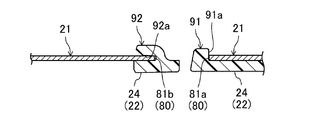
図9に示すように、切り欠き部(81)および突起部(91)は、ガイドレール(21)の長手方向の一端部(この例では車両前側の端部)とフレーム延出部(24)とが重なる方向(この例では上下方向)において突起部(91)の移動が規制されるように構成されていてもよい。なお、図9は、図5のVI−VI線における断面図に対応している。
(
As shown in FIG. 9, the notch (81) and the projection (91) are one end of the guide rail (21) in the longitudinal direction (in this example, the end on the vehicle front side) and the frame extension (24). The movement of the projection (91) may be restricted in a direction (in this example, the up-down direction in this example) where the. 9 corresponds to the cross-sectional view taken along the line VI-VI of FIG.
図9の例では、突起部(91)の第1側部(91a)に爪部(900)が設けられている。爪部(900)は、突起部(91)の第1側部(91a)から突出してフレーム延出部(24)との間に切り欠き部(81)の第1縁部(81a)を挟持している。このような構成により、ガイドレール(21)の長手方向の一端部とフレーム延出部(24)とが重なる方向において突起部(91)の移動を規制することができる。 In the example of FIG. 9, the claw portion (900) is provided on the first side (91a) of the projection (91). The claw portion (900) protrudes from the first side portion (91a) of the projection portion (91) and holds the first edge portion (81a) of the notch portion (81) between it and the frame extension portion (24). doing. With such a configuration, the movement of the projection (91) can be restricted in the direction in which one end of the guide rail (21) in the longitudinal direction and the frame extension (24) overlap.
以上のように、ガイドレール(21)の長手方向の一端部とフレーム延出部(24)とが重なる方向において突起部(91)の移動が規制されるように切り欠き部(81)と突起部(91)とを構成することにより、ガイドレール(21)の長手方向の一端部とフレーム延出部(24)とが重なる方向に突起部(91)が移動して突起部(91)が切り欠き部(81)から抜け出すことを防止することができる。これにより、ガイドレール(21)と第1フレーム(22)との連結を強化することができる。 As described above, the notch (81) and the projection are controlled such that the movement of the projection (91) is restricted in the direction in which the one end of the guide rail (21) in the longitudinal direction and the frame extension (24) overlap. By forming the portion (91), the protrusion (91) moves in a direction in which one end of the guide rail (21) in the longitudinal direction and the frame extension (24) overlap with each other, and the protrusion (91) It can prevent coming out of a notch (81). Thereby, the connection between the guide rail (21) and the first frame (22) can be strengthened.
なお、図9に示すように、突起部(91)の第1側部(91a)に爪部(900)が設けられている場合、差込部(92)が省略されていてもよい。 In addition, as shown in FIG. 9, when the nail | claw part (900) is provided in the 1st side part (91a) of a projection part (91), the insertion part (92) may be abbreviate | omitted.
(その他の実施形態)
以上の説明において、切り欠き部(81)がガイドレール(21)の長手方向の一端部の車両内側に設けられて車両内側へ向けて開口している場合を例に挙げたが、切り欠き部(81)は、ガイドレール(21)の長手方向の一端部の車両外側に設けられて車両外側へ向けて開口していてもよい。この場合、切り欠き部(81)の開口側が車両外側となり、切り欠き部(81)の奥側が車両内側となる。なお、この場合、突起部(91)と差込部(92)は、切り欠き部(81)と同様に、フレーム延出部(24)の車両外側に設けられることになる。
(Other embodiments)
In the above description, although the case where the notch (81) is provided inside the vehicle at one end of the guide rail (21) in the longitudinal direction and opens toward the vehicle inside is taken as an example, the notch is (81) may be provided on the vehicle outer side at one end in the longitudinal direction of the guide rail (21) and open toward the vehicle outer side. In this case, the opening side of the notch (81) is the outside of the vehicle, and the back side of the notch (81) is the inside of the vehicle. In this case, the projection (91) and the insertion part (92) are provided on the vehicle outer side of the frame extension part (24), similarly to the notch part (81).
また、以上の説明では、第1フレーム(22)がルーフ開口部(2)の車両前側の縁部に配置されてフロントフレームを構成している場合を例に挙げたが、第1フレーム(22)は、ルーフ開口部(2)の車両後側の縁部に配置されてフロントフレームを構成するものであってもよい。この場合、フレーム延出部(24)は、フレーム本体(23)の長手方向の端部から車両前側に延出してガイドレール(21)の長手方向の一端部(車両後側の端部)に重なることになる。すなわち、この場合、ガイドレール(21)の長手方向の一端側が車両後側となり、ガイドレール(21)の長手方向の他端側が車両前側となる。 In the above description, the first frame (22) is disposed at the edge of the roof opening (2) on the front side of the vehicle to form the front frame. ) May be disposed at the rear edge of the roof opening (2) to constitute a front frame. In this case, the frame extension part (24) extends from the longitudinal end of the frame body (23) to the front side of the vehicle and at one end (end on the vehicle rear side) of the guide rail (21) in the longitudinal direction. It will overlap. That is, in this case, one end side in the longitudinal direction of the guide rail (21) is the rear side of the vehicle, and the other end side in the longitudinal direction of the guide rail (21) is the front side of the vehicle.
また、以上の実施形態および変形例を適宜組み合わせて実施してもよい。以上の実施形態および変形例は、本質的に好ましい例示であって、この発明、その適用物、あるいはその用途の範囲を制限することを意図するものではない。 In addition, the above embodiment and modifications may be combined as appropriate. The above embodiments and modifications are essentially preferred exemplifications, and are not intended to limit the scope of the present invention, the applications thereof, or the applications thereof.
以上説明したように、この発明は、サンルーフ装置について有用である。 As described above, the present invention is useful for a sunroof device.
1 ルーフ
2 ルーフ開口部
3 窓部
10 サンルーフ装置
20 フレームアセンブリ
21 ガイドレール
22 第1フレーム
23 フレーム本体
24 フレーム延出部
25 第2フレーム
30 ハウジング
40 可動パネル
41 フロント側固定パネル
42 リア側固定パネル
50 駆動機構
51 スライド部材
52 プッシュプルケーブル
53 モータ
61 第1ロールシェード装置
62 第2ロールシェード装置
71 第1プッシュプルケーブル
72 第1モータ
75 第2プッシュプルケーブル
76 第2モータ
81 切り欠き部
81a 第1縁部
81b 第2縁部
82 係合穴
83 係合片
90 壁部
91 突起部
91a 第1側部
92 差込部
93 補助突起部
94 係合部
900 爪部
Reference Signs List 1
Claims (7)
上記ルーフ開口部(2)の車幅方向の縁部に沿うように延びる一対のガイドレール(21)と、該ルーフ開口部(2)の車両前後方向の縁部に配置される第1フレーム(22)とを有するフレームアセンブリ(20)と、
上記一対のガイドレール(21)により車両前後方向にスライド可能に支持される可動パネル(40)とを備え、
上記第1フレーム(22)は、上記ルーフ開口部(2)の車両前後方向の縁部に沿うように延びるフレーム本体(23)と、該フレーム本体(23)の長手方向の端部から車両前後方向に延出して上記ガイドレール(21)の長手方向の一端部に重なるフレーム延出部(24)とを有し、
上記ガイドレール(21)の長手方向の一端部には、該ガイドレール(21)の短手方向に開口する切り欠き部(81)が設けられ、
上記フレーム延出部(24)には、上記ガイドレール(21)の切り欠き部(81)と係合するように構成された突起部(91)が設けられている
ことを特徴とするサンルーフ装置。 A sunroof device provided in a roof opening (2) of a vehicle, comprising:
A pair of guide rails (21) extending along the edge of the roof opening (2) in the vehicle width direction, and a first frame (1) arranged at the edge of the roof opening (2) in the vehicle longitudinal direction 22) a frame assembly (20),
A movable panel (40) slidably supported in the longitudinal direction of the vehicle by the pair of guide rails (21);
The first frame (22) extends from the frame main body (23) extending along the edge of the roof opening (2) in the longitudinal direction of the vehicle, and the longitudinal end of the frame main body (23) And a frame extension (24) extending in the direction and overlapping one end of the guide rail (21) in the longitudinal direction,
At one end of the guide rail (21) in the longitudinal direction, a notch (81) opened in the short direction of the guide rail (21) is provided.
A sunroof device characterized in that the frame extension (24) is provided with a projection (91) configured to engage with the notch (81) of the guide rail (21). .
上記フレーム延出部(24)には、上記突起部(91)よりも該フレーム延出部(24)の基端側に配置されて上記ガイドレール(21)の長手方向の一端部と接触するように構成された壁部(90)が設けられている
ことを特徴とするサンルーフ装置。 In claim 1,
The frame extension (24) is disposed closer to the base end of the frame extension (24) than the projection (91) and contacts one end of the guide rail (21) in the longitudinal direction. A sunroof device, characterized in that it is provided with a wall (90) configured as such.
上記切り欠き部(81)および上記突起部(91)は、該切り欠き部(81)の奥側から開口側へ向かう該突起部(91)の移動が規制されるように構成されている
ことを特徴とするサンルーフ装置。 In claim 1 or 2,
The notch (81) and the projection (91) are configured such that movement of the protrusion (91) from the back side of the notch (81) toward the opening is restricted. A sunroof device characterized by
上記切り欠き部(81)は、上記ガイドレール(21)の長手方向の他端側を向く第1縁部(81a)を有し、
上記突起部(91)は、上記切り欠き部(81)の第1縁部(81a)と接触する第1側部(91a)を有し、
上記切り欠き部(81)の第1縁部(81a)と上記突起部(91)の第1側部(91a)は、該切り欠き部(81)の開口側から奥側へ向けて上記ガイドレール(21)の長手方向の他端側から一端側に傾斜するように構成されている
ことを特徴とするサンルーフ装置。 In claim 3,
The notch (81) has a first edge (81a) facing the other end side of the guide rail (21) in the longitudinal direction,
The protrusion (91) has a first side (91a) in contact with the first edge (81a) of the notch (81);
The first edge (81a) of the notch (81) and the first side (91a) of the protrusion (91) are directed from the opening side of the notch (81) toward the back A sunroof device characterized in that it is configured to be inclined from the other end side in the longitudinal direction of the rail (21) to one end side.
上記切り欠き部(81)は、上記ガイドレール(21)の長手方向の他端側を向く第1縁部(81a)を有し、
上記突起部(91)は、上記切り欠き部(81)の第1縁部(81a)と接触する第1側部(91a)を有し、
上記切り欠き部(81)の第1縁部(81a)と上記突起部(91)の第1側部(91a)は、平面視において階段状に形成されている
ことを特徴とするサンルーフ装置。 In claim 3,
The notch (81) has a first edge (81a) facing the other end side of the guide rail (21) in the longitudinal direction,
The protrusion (91) has a first side (91a) in contact with the first edge (81a) of the notch (81);
A sunroof device, wherein the first edge (81a) of the notch (81) and the first side (91a) of the protrusion (91) are formed in a step shape in plan view.
上記切り欠き部(81)および上記突起部(91)は、上記ガイドレール(21)の長手方向の一端部と上記フレーム延出部(24)とが重なる方向において該突起部(91)の移動が規制されるように構成されている
ことを特徴とするサンルーフ装置。 In any one of claims 1 to 5,
The notch (81) and the protrusion (91) move the protrusion (91) in a direction in which one end of the guide rail (21) in the longitudinal direction and the frame extension (24) overlap. A sunroof device, characterized in that it is configured to be regulated.
上記切り欠き部(81)は、上記ガイドレール(21)の長手方向の他端側を向く第1縁部(81a)を有し、
上記突起部(91)は、上記切り欠き部(81)の第1縁部(81a)と接触する第1側部(91a)を有し、
上記突起部(91)の第1側部(91a)には、該突起部(91)の第1側部(91a)から突出して上記フレーム延出部(24)との間に上記切り欠き部(81)の第1縁部(81a)を挟持する爪部(900)が設けられている
ことを特徴とするサンルーフ装置。 In claim 6,
The notch (81) has a first edge (81a) facing the other end side of the guide rail (21) in the longitudinal direction,
The protrusion (91) has a first side (91a) in contact with the first edge (81a) of the notch (81);
The first side portion (91a) of the protrusion (91) protrudes from the first side portion (91a) of the protrusion (91) and the notch portion between the frame extension portion (24) A sunroof device comprising a claw portion (900) for holding the first edge (81a) of (81).
Priority Applications (1)
| Application Number | Priority Date | Filing Date | Title |
|---|---|---|---|
| JP2017166967A JP2019043295A (en) | 2017-08-31 | 2017-08-31 | Sunroof device |
Applications Claiming Priority (1)
| Application Number | Priority Date | Filing Date | Title |
|---|---|---|---|
| JP2017166967A JP2019043295A (en) | 2017-08-31 | 2017-08-31 | Sunroof device |
Publications (1)
| Publication Number | Publication Date |
|---|---|
| JP2019043295A true JP2019043295A (en) | 2019-03-22 |
Family
ID=65815304
Family Applications (1)
| Application Number | Title | Priority Date | Filing Date |
|---|---|---|---|
| JP2017166967A Pending JP2019043295A (en) | 2017-08-31 | 2017-08-31 | Sunroof device |
Country Status (1)
| Country | Link |
|---|---|
| JP (1) | JP2019043295A (en) |
-
2017
- 2017-08-31 JP JP2017166967A patent/JP2019043295A/en active Pending
Similar Documents
| Publication | Publication Date | Title |
|---|---|---|
| JP4797091B2 (en) | Shade panel interlocking mechanism in sunroof equipment | |
| US7828376B2 (en) | Open roof construction for a vehicle | |
| EP3832060B1 (en) | Power slide window | |
| CN108790744B (en) | Electric sunshade curtain and skylight structure | |
| JP5091934B2 (en) | Blind cover positioning structure | |
| EP3832061B1 (en) | Power slide window | |
| US9592723B2 (en) | Vehicle sunroof device | |
| EP2226209A1 (en) | Roof assembly for a vehicle | |
| JP2004256090A (en) | Sun-visor for open roof structure and open roof structure having sun-visor | |
| CN110562017A (en) | roof system for a vehicle | |
| JP4902629B2 (en) | Impulse regulating device for slide panel in sunroof device | |
| EP2353905A1 (en) | Open roof construction for a vehicle | |
| JP5849450B2 (en) | Sunshade equipment | |
| CN205149477U (en) | A open skylight structure for vehicle | |
| JP4203515B2 (en) | Vehicle sunshade device | |
| CN214647505U (en) | Sunroof device | |
| JP3781356B2 (en) | Side window opening and closing mechanism for vehicles | |
| JP4578421B2 (en) | Opening / closing body slide structure | |
| JP2003326976A (en) | Sunroof equipment | |
| JP5879922B2 (en) | Shade stopper | |
| JP2011079449A (en) | Sunshade device | |
| JP3258915B2 (en) | Structure of automobile side door | |
| JP2003211966A (en) | Sunroof equipment | |
| JP4246759B2 (en) | Multi-plate sunshade device | |
| JP2008149924A (en) | Vehicle door |