JP2019059228A - Production method of prism, prism, and mold - Google Patents
Production method of prism, prism, and mold Download PDFInfo
- Publication number
- JP2019059228A JP2019059228A JP2018157415A JP2018157415A JP2019059228A JP 2019059228 A JP2019059228 A JP 2019059228A JP 2018157415 A JP2018157415 A JP 2018157415A JP 2018157415 A JP2018157415 A JP 2018157415A JP 2019059228 A JP2019059228 A JP 2019059228A
- Authority
- JP
- Japan
- Prior art keywords
- mold
- prism
- optical
- respect
- die
- Prior art date
- Legal status (The legal status is an assumption and is not a legal conclusion. Google has not performed a legal analysis and makes no representation as to the accuracy of the status listed.)
- Pending
Links
Images



Landscapes
- Moulds For Moulding Plastics Or The Like (AREA)
- Casting Or Compression Moulding Of Plastics Or The Like (AREA)
- Telescopes (AREA)
- Optical Elements Other Than Lenses (AREA)
Abstract
【課題】プリズムの光学面にヒケが発生するのを抑制する。【解決手段】素材9が積載された下型51を、胴型52及び上型53に対向する位置に配置する。胴型52を下降させることで、下型51と胴型52とで素材9を挟み込む。上型53を胴型52に対して下方向に摺動させることで、上型53を面C1mに対し素材9の側に突出させて、素材9を押圧し、素材9に光学面を転写する。上型53は、非光学面に対応する。その後、素材9を冷却する。【選択図】図6An object of the present invention is to suppress generation of sink marks on an optical surface of a prism. A lower die 51 on which a material 9 is loaded is disposed at a position facing a barrel die 52 and an upper die 53. By lowering the body mold 52, the material 9 is sandwiched between the lower mold 51 and the body mold 52. By sliding the upper mold 53 downward with respect to the body mold 52, the upper mold 53 is made to protrude to the side of the material 9 with respect to the surface C1m, and the material 9 is pressed to transfer the optical surface to the material 9 . The upper mold 53 corresponds to the non-optical surface. Thereafter, the material 9 is cooled. [Selected figure] Figure 6
Description
本発明は、プリズムの製造方法、プリズム及びプリズムの製造に用いる成形型に関する。 The present invention relates to a method of manufacturing a prism, a prism and a mold used for manufacturing the prism.
従来、プリズムの製造方法として、例えば成形素材のブロックを研磨する方法がある。しかし、この方法では、加工工程が多く、高精度の加工技術を必要とするので、製造コストが高い。そこで、製造コストを抑える加工技術が検討されてきている。 Conventionally, as a method of manufacturing a prism, for example, there is a method of polishing a block of a forming material. However, this method requires many processing steps and requires high-precision processing technology, so the manufacturing cost is high. Therefore, processing techniques for reducing the manufacturing cost have been studied.
特許文献1には、プレス成形によって成形品を製造する方法が開示されている。特許文献1の方法により、加熱された型で素材をプレスし、徐冷を行うことで、プレス時の樹脂流動による歪みや冷却固化中の温度分布による歪みを低減することができる。 Patent Document 1 discloses a method of producing a molded article by press molding. By pressing the material with a heated mold and performing slow cooling according to the method of Patent Document 1, distortion due to resin flow during pressing and distortion due to temperature distribution during cooling and solidification can be reduced.
しかし、プリズムを製造する場合、プリズムは厚肉の成形品であるため、冷却収縮によってヒケが発生する。プリズムの光学面にヒケが発生すると、光学面の精度が低下する問題があった。 However, in the case of manufacturing a prism, since the prism is a thick-walled molded product, sinking occurs due to cooling shrinkage. When a sink occurs on the optical surface of the prism, there is a problem that the accuracy of the optical surface is lowered.
そこで、本発明は、プリズムの光学面にヒケが発生するのを抑制することを目的とする。 Therefore, an object of the present invention is to suppress the occurrence of sink marks on the optical surface of a prism.
本発明のプリズムの製造方法は、光学面及び非光学面を有するプリズムの製造方法であって、第1の型と、前記非光学面の基面を形成する面を有する第2の型とで素材を挟み込む第1の工程と、前記基面に対して凹む凹部を形成する第3の型を、前記基面を形成する面に対し前記素材の側に突出させて、前記素材を押圧する第2の工程と、前記素材を冷却する第3の工程と、を備える、ことを特徴とする。 A method of manufacturing a prism according to the present invention is a method of manufacturing a prism having an optical surface and a non-optical surface, which is a first type and a second type having a surface forming the base surface of the non-optical surface. The first step of sandwiching the material, and the third mold for forming the concave portion recessed with respect to the base surface is protruded to the side of the material with respect to the surface forming the base surface, and the material is pressed And a third step of cooling the material.
本発明によれば、光学面の精度が高いプリズムを得ることができる。 According to the present invention, it is possible to obtain a prism with high optical surface precision.
以下、本発明を実施するための形態を、図面を参照しながら詳細に説明する。
[第1実施形態]
図1(a)は、第1実施形態におけるプリズム90の斜視図である。光学素子であるプリズム90は、双眼鏡やカメラ等の光学機器に装備される。プリズム90は、例えば三角プリズムであり、鏡面対称面P1に対して面対称な形状となっている。プリズム90の素材は、ガラスでもよいが、ガラスよりも軽量であり低コストである熱可塑性樹脂としている。
Hereinafter, embodiments of the present invention will be described in detail with reference to the drawings.
First Embodiment
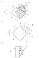
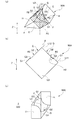
FIG. 1A is a perspective view of the
プリズム90は、3つの光学面A,A,Dと、2つの非光学面B,Cと、を有する略三角柱状に形成されている。光学面A,A,Dは、三角柱の側面であり、非光学面B,Cは、三角柱の下面と上面である。鏡面対称面P1は、図1(a)中、プリズム90の稜線I、光学面Dを二分割する仮想線、及び上下方向Zに延びる仮想軸線L0を含む仮想面である。図1(b)は、鏡面対称面P1におけるプリズム90の断面図である。図1(c)は、仮想軸線L0の延びる方向に見たプリズム90の平面図である。
The
光学面A,A,D及び非光学面Bは平面であり、非光学面Cは、平面である基面C1と、基面C1に対して凹む凹部Rと、を有する。凹部Rは、ほぼ平面状の底面C2と、底面C2を囲むように立設された側壁面C3と、を含んでいる。非光学面Bと、非光学面Cの基面C1及び底面C2とは平行である。また、光学面A,A,Dと、非光学面B並びに非光学面Cの基面C1及び底面C2とは、垂直(90度)である。光学面A,A同士のなす角は90度であり、光学面Aと光学面Dとのなす角は45度である。 The optical surfaces A, A, D and the non-optical surface B are flat, and the non-optical surface C has a base surface C1 which is a flat surface and a recess R recessed with respect to the base surface C1. The recess R includes a substantially planar bottom surface C2 and a side wall surface C3 erected so as to surround the bottom surface C2. The non-optical surface B and the base surface C1 and the bottom surface C2 of the non-optical surface C are parallel. The optical surfaces A, A and D, and the non-optical surface B and the base surface C1 and the bottom surface C2 of the non-optical surface C are perpendicular (90 degrees). The angle between the optical surfaces A and A is 90 degrees, and the angle between the optical surfaces A and D is 45 degrees.
なお、基面C1と底面C2とは平行である。よって、基面C1の法線L1と底面C2の法線L2とは平行である。即ち法線L1と法線L2とは同じ方向に延びている。仮想軸線L0と法線L1,L2とのなす角度をθとする。仮想軸線L0と法線L1,L2とのなす角度には、合計すると180度となる2つの角度、即ち鋭角の角度と鈍角の角度とが存在するが、角度θは鋭角の角度とする。また、仮想軸線L0は、プリズム90が成形型内にあるときに成形型のプレス軸線と一致する線である。
The base surface C1 and the bottom surface C2 are parallel to each other. Therefore, the normal line L1 of the base plane C1 and the normal line L2 of the bottom plane C2 are parallel. That is, the normal line L1 and the normal line L2 extend in the same direction. The angle between the imaginary axis L0 and the normals L1 and L2 is θ. The angle between the imaginary axis L0 and the normals L1 and L2 has two angles of 180 degrees in total, ie, an acute angle and an obtuse angle, but the angle θ is an acute angle. The imaginary axis L0 is a line which coincides with the press axis of the mold when the
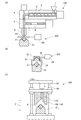
図2(a)は、第1実施形態に係るプリズム90の製造に用いる吐出装置100及び切断装置200を示す説明図である。図2(b)は、第1実施形態に係るプリズム90の製造に用いる加熱装置300を示す説明図である。図2(c)は、第1実施形態に係るプリズム90の製造に用いるプレス装置500を示す説明図である。図2(a)に示す吐出装置100及び切断装置200、図2(b)に示す加熱装置300、並びに図2(c)に示すプレス装置500により、プリズム90を製造する製造システムが構成されている。
FIG. 2A is an explanatory view showing the
図2(a)に示す吐出装置100は、ホッパー1と、可塑化部としてのスクリュー2とを備える。ホッパー1には、プリズム90の素材9となる熱可塑性樹脂が投入される。ホッパー1に投入される熱可塑性樹脂は、樹脂固化材料であり、例えば数mm程度の取り扱いやすい大きさのペレットとする。スクリュー2は、ホッパー1に投入された熱可塑性樹脂を加熱混練して可塑化する。
The
また、吐出装置100は、スクリュー2を収容するバレル3を備える。バレル3には、上部マニホールド4、下部マニホールド5及びノズル6が接続して設けられている。上部マニホールド4には、スクリュー2から供給される溶融樹脂の流路が形成されている。下部マニホールド5には、ノズル6から溶融樹脂が吐出するように加圧するための加圧室7が形成されている。
Further, the
また、吐出装置100は、加圧室7に摺動可能に配置されたプランジャ8を備える。プランジャ8は、精密な前後移動を可能とし、加圧室7に充填された溶融樹脂を押圧する。プランジャ8の動作により、加圧室7に充填された溶融樹脂は、ノズル6から下方に吐出される。吐出された素材9は、下型51で受け止められ、溶融樹脂塊を形成する。
The
なお、吐出装置100は、射出成形で用いられるスクリュープリプラ式の可塑化射出装置であるが、インラインスクリュー式の可塑化射出装置であってもよく、また、溶融樹脂の吐出量が一定であれば、いかなる吐出方式のものでもよい。また、ノズル形状や材質、あるいは吐出速度等は目的に応じて決定すればよい。
In addition, although the
図2(a)に示す切断装置200は、ノズル6近傍に配置された一対の刃を有するカッター等の切断治具21と、切断治具21を駆動する駆動部22とを備えており、ノズル6から下方に連なる素材9を切断するものである。切断装置200は、例えばエアーニッパーである。
The
図2(b)に示す加熱装置300は、熱源としてのハロゲンヒータ31と、ハロゲンヒータ31の外周を覆うように配置された反射鏡32と、反射鏡32と下型51との間の空間を囲うカバー33と、を有する。反射鏡32は、直下で焦点が合うように形成されている。反射鏡32の焦点位置及びその近傍に素材9の一部分が配置された場合、その一部分を局所的に加熱することができる。加熱装置300は、不活性ガス供給源34と、加熱装置300に配置された素材9の周囲に不活性ガス(例えば窒素ガス、アルゴンガス等)を噴出するノズル35と、を備え、カバー33の内部を不活性ガスの雰囲気に保つ。
The
図2(c)に示すプレス装置500は、プレス成形するためのものであり、成形型50を有する。成形型50は、第1の型である下型51、第2の型である胴型52、及び第3の型である上型53からなるプリズム成形用の金型である。プレス装置500は、胴型52及び上型53をプレス軸線L0mの延びる方向である上下方向Zに案内する移動ガイド54と、上型53を上下方向Zに駆動する駆動部55と、胴型52を上下方向Zに駆動する不図示の駆動部と、を有している。素材9が載置された下型51を、胴型52及び上型53に上下方向Zで対向する位置に搬送し、胴型52及び上型53を下降させることで、素材9をプレス成形することができる。プレス軸線L0mは、駆動部55の中心を通る仮想的な線である。つまり、上型53をプレス軸線L0mに沿って下降させることにより、プレス成形を行う。
The
下型51は、吐出装置100、加熱装置300、及びプレス装置500に順次搬送可能となっている。下型51は、吐出装置100及び加熱装置300においては、素材9が載置される共通の受け皿であり、プレス装置500においては、成形型50の一部となる。下型51は、不図示の搬送装置、例えばロボットにより搬送される。本実施形態では、吐出装置100とは別にプレス装置500を生産ラインに配置し、複数の下型51を各装置100,300,500に順次搬送するようにしている。このように、下型51を共通の受け皿として搬送することにより、連続的に生産を行うことができ、プリズム90の大量生産が可能となり、プリズム90の生産性が向上する。
The
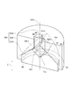
図3は、第1実施形態における成形型50を切断したときの一対の切断片のうち一方を示す斜視図である。図3には、プレス軸線L0mを含む面であってキャビティCVを2分割する鏡面対称面(図1(a)の鏡面対称面P1に相当)で成形型50を切断して図示している。キャビティCVは、素材9にプリズム90の形状を転写するために、素材9が配置される空間である。なお、成形型50のキャビティCVにプリズム90が配置されている状態では、図1(a)に示す仮想軸線L0とプレス軸線L0mとは重なる。
FIG. 3 is a perspective view showing one of a pair of cut pieces when the
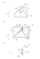
図4(a)は下型51を切断したときの一対の切断片のうち一方を示す斜視図である。図4(b)は胴型52を切断したときの一対の切断片のうち一方を示す斜視図である。図4(c)は上型53を切断したときの一対の切断片のうち一方を示す斜視図である。図4(a)〜図4(c)においても、図3と同様の鏡面対称面で各型を切断して図示している。
FIG. 4A is a perspective view showing one of a pair of cut pieces when the
下型51は、図4(a)に示すように、プリズム90の光学面Aを形成する面である光学面Amと、プリズム90の非光学面Bを形成する面である非光学面Bmと、を有する。また、下型51は、当接面61及び摺接面65を有する。
The
胴型52は、図4(b)に示すように、プリズム90の光学面Dを形成する面である光学面Dmと、プリズム90の非光学面Cの一部である基面C1を形成する面C1mと、を有する。また、胴型52は、当接面62、摺接面64及び摺接面66を有する。
The
上型53は、プリズム90の非光学面Cの他部である凹部Rを形成するものであり、胴型52に対して上下方向Zに摺動自在である。上型53は、図4(c)に示すように、凹部Rの底面C2を形成する押圧面C2mと、押圧面C2mに連続する摺接面63と、を有する。押圧面C2mは、外周が直線及び円弧で形成されており、摺接面63を精度良く加工できる形状になっている。
The upper die 53 forms a recess R which is the other part of the non-optical surface C of the
図3に示すように、摺接面63,64,65,66は、プレス軸線L0mと平行な方向、即ち上下方向Zに延びる面である。下型51に対して胴型52を上下方向Zに移動させることにより、下型51の摺接面65と胴型52の摺接面66とが摺接する。また、胴型52に対して上型53を上下方向Zに移動させることにより、胴型52の摺接面64と上型53の摺接面63とが摺接する。当接面62は、当接面61と重なり合う形状に形成されている。
As shown in FIG. 3, the sliding contact surfaces 63, 64, 65, 66 are surfaces extending in a direction parallel to the press axis L0m, that is, in the up-down direction Z. By moving the
胴型52は、下型51の摺接面65に摺接して下型51に対して上下方向Zに摺動することにより、プレス軸線L0mに軸合わせがなされる。また、胴型52は、当接面62が下型51の当接面61に当接することで、上下方向Zの位置決めがなされる。上型53は、胴型52の摺接面64に摺接して胴型52に対して上下方向Zに摺動することにより、プレス軸線L0mに軸合わせがなされる。また、上型53を胴型52に対して摺動させることで、押圧面C2mを通じて素材9にプレス圧を伝達し、各面Am,Am,Bm,Cm,Dmの転写が行われる。
The cylinder die 52 is in sliding contact with the sliding
光学面Am,非光学面Bm,非光学面Cmの面C1m及び押圧面C2m,光学面Dmは、全てプレス軸線L0mに対して傾斜する傾斜面である。即ち、面C1m及び押圧面C2mは、摺接面63に対して傾斜する傾斜面である。また、胴型52及び上型53は、面C1mと押圧面C2mとが平行となるように配置されている。即ち、面C1mの法線L1mと面C2mの法線L2mとは平行である。つまり、法線L1mと法線L2mとは同じ方向に延びている。プレス軸線L0mと法線L1m,L2mとの成す角度は、図1(b)に示す角度θと一致する。
The optical surface Am, the non-optical surface Bm, the surface C1m of the non-optical surface Cm, the pressing surface C2m, and the optical surface Dm are all inclined surfaces inclined with respect to the press axis L0m. That is, the surface C1m and the pressing surface C2m are inclined surfaces that are inclined with respect to the sliding
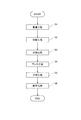
次に、上述の製造システムを用いたプリズム90の製造方法について詳細に説明する。図5は、プリズム90の製造方法の各工程を示すフローチャートである。図5に示すように、載置工程S1、切断工程S2、加熱工程S3、プレス工程S4、冷却工程S5、離型工程S6を経て、プリズム90が製造される。以下、各工程について具体的に説明する。なお、以下の説明では、熱可塑性樹脂として、シクロオレフィンポリマー(COP)樹脂(例えば、日本ゼオン社製のZEONEX(登録商標)E48R、ガラス転移温度Tg:140℃)を使用する場合を例に説明するが、この材料に限るものではない。
Next, a method of manufacturing the
まず、載置工程S1において、図2(a)に示すように、不図示の搬送装置により下型51をノズル6の下方に移動させ、下型51に溶融した素材9をノズル6より吐出させる。具体的には、吐出装置100によりCOP樹脂をTg+50℃以上Tg+150℃以下で可塑化させて、下型51に大気中で吐出する。下型51の材質は、例えばステンレス、銅合金、超硬合金である。
First, in the placement step S1, as shown in FIG. 2A, the
下型51は、溶融樹脂が下型51に接した時に吐出による樹脂流動痕が残らないようにするため、高温にする必要がある。第1実施形態では、下型51をTg+10℃以上Tg+150℃以下(例えば180℃)に加熱保温している。搬送装置のうち、下型51を把持する部分は、接触により下型51を急激に冷却しないようにするため、断熱する必要がある。例えば把持する部分の素材として、耐熱性が高く熱伝導率の低いポリエーテルエーテルケトン(PEEK)樹脂が用いられる。
The
成形されるプリズム90は厚肉であり、その形状を成形するために必要な量の素材9をプリズム90に概ね近い形状に吐出する必要がある。仮に素材9が下型51から溢れた場合、プレス工程S4において下型51の当接面61と胴型52の当接面62との間に樹脂が挟まり、成形されるプリズムに成形不良であるバリが発生する。第1実施形態では、下型51を下方及び水平方向に移動させながら、素材9の吐出を行う。下型51の動作と素材9の吐出速度を調整することで、素材9を所望の形状に吐出することができる。
The
周囲環境が大気の場合、環境温度が溶融樹脂のTgよりも低いため、吐出された素材9は大気により冷却されていく。特に素材9の表面は徐々に固化していく。周囲環境の温度を素材9のTgに近づける、若しくはTg以上にすることにより、素材9の表面固化を遅らせることができる。また、大気中の酸素により素材9の酸化劣化が発生する場合は、素材9の周囲を密閉容器等で囲い、不活性ガス(例えば窒素)雰囲気下にすることで、これを防止することができる。
When the ambient environment is the air, the discharged
載置工程S1の終了後、ノズル6からの素材9の供給は停止しているが、素材9の粘度により素材9がノズル6に連なっている状態である。粘度と比重の関係から、熱可塑性樹脂はガラスと異なり、自発的な切断、即ちシャーレスカットができないため、ノズル6の先端から素材9がぶら下がる形態になる。
Although the supply of the
このため、第1実施形態では、切断工程S2において、図2(a)に示す駆動部22により切断治具21を動作させて、素材9をノズル6から切断する。このように、下型51に吐出した素材9を切断装置200で切断分離することで、上部に先細りの突起形状を持つ素材9が得られる。切断治具21は、鋭利な刃先を有するものや、樹脂を保持してから下方に引き切断するもののうち、適したものを選択すればよい。切断装置200の切断治具21は、不図示のヒータにより昇温させたものを用いても良いが、温度を上げ過ぎると切断治具21に溶融樹脂が貼り付いてしまうため、貼り付きが生じない程度に昇温するのがよい。
For this reason, in the first embodiment, the cutting
以上の切断工程S2が終了すると、下型51上には素材9が載置されている。素材9の上部は、切断工程S2で生じた先細りの突起部となる。突起部の先端における切断部分には、切断治具21によって形成された切断痕が残る。素材9は、外気との接触により、その温度が下がり始め、粘性が上がり、形状自由度が次第に低下する。素材9には、突起部、及び突起部の先端に切断痕があるため、良好なプリズム90を得るためには、突起形状を補正する必要がある。
When the above-described cutting step S2 is completed, the
そこで、加熱工程S3において、下型51上に載置された素材9の突起部を局所的に加熱する。以下、加熱工程S3について具体的に説明する。図2(b)に示すように、素材9が載置された下型51を、不図示の搬送装置で加熱装置300に移動させる。素材9の突起部の上方にハロゲンヒータ31が位置するように、具体的には素材9の突起部の先端がハロゲンヒータ31から放射される赤外線の焦点付近に位置するように、下型51を搬送装置により移動させる。この状態でハロゲンヒータ31に加熱動作をさせることにより、赤外線が突起部の先端に集光され、突起部の先端が局所的に加熱装置300に対して非接触状態で加熱されることになる。
Therefore, in the heating step S3, the protrusions of the
素材9の突起部は、加熱されると樹脂流動により次第に消失していく。消失に合わせてハロゲンヒータ31を下方に移動させ、常に赤外線が素材9の突起部先端に位置するように調整することで、スムーズに短時間で切断痕及び突起形状を除去した素材9が得られる。なお、型を押し当てるなどの接触方式で加熱すると、加熱装置への樹脂の貼り付きの原因となるため、本実施形態のように非接触で加熱を行うのがよい。
When heated, the protrusions of the
また、加熱動作時、ハロゲンヒータ31を移動させず、例えば素材9の突起部の根元に赤外線を集光させるように構成すると、突起部根元付近の粘度が局所的に低下して突起部が倒れることがあり、成形面の転写不良の原因となる。また、突起部除去に必要な赤外線の照射時間が増し、黄変等の外観不良の原因にもつながる。本実施形態では、ハロゲンヒータ31を移動させながら突起部先端に局所加熱を行うことにより、外観不良を抑制するとともに、素材9全体の樹脂流動を抑え、下型51から素材9が溢れるのを防ぐことができる。なお、ハロゲンヒータ31による素材9の加熱時間は約20秒程度である。
In addition, during heating operation, if the
以上の説明では熱源としてハロゲンヒータ31の場合について説明したが、これに限定するものではなく、素材9を輻射加熱できるものであればよい。例えば、カーボンヒータや、中赤外線ヒータ、遠赤外線ヒータを用いてもよい。これらヒータは、ハロゲンヒータと同様に、COP樹脂を加熱することができる。また素材9の上方にハロゲンヒータ31を設置する以外にも、側方に設置して横から素材9の突起部を加熱したり、リング状の光源を用いて突起部を周囲から加熱したりしてもよい。
Although the case of the
ところで、樹脂は加熱されることで化学反応が促進され変質の可能性が増すが、特に、加熱した際に素材9の周囲に酸素が十分にある環境では、樹脂成分が酸化により変質する可能性が高い。そのため、本実施形態では、加熱工程S3において、加熱による温度上昇によって素材9が酸化劣化することを防止するため、不活性ガス供給源34によりカバー33内を不活性ガス(例えば窒素ガスやアルゴンガス)で満たすようにしている。これにより、素材9のまわりは不活性ガスの雰囲気に保つことができ、素材9の酸化を防止することができる。
By the way, although the resin is heated, the chemical reaction is promoted and the possibility of deterioration increases, but in the environment where oxygen is sufficiently around the
なお、第1実施形態では、載置工程S1において、下型51に溶融樹脂である素材9を吐出する場合について説明したが、これに限定するものではなく、プリズム90のニアシェープゴブや樹脂ブロック体を素材9としてもよい。この場合、切断工程S2及び加熱工程S3の代わりに、樹脂全体を溶融状態まで加熱する加熱工程を行えばよい。
In the first embodiment, the case where the
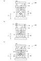
次に、プレス工程S4について説明する。図6(a)〜図6(c)は、プレス工程の説明図である。まず、図6(a)に示すように、下型51と素材9を、温度制御された胴型52及び上型53の下方に配置する。次いで図6(b)に示すように、胴型52及び上型53を、移動ガイド54によって下型51に向けて下方向Z1に移動させる(第1の工程)。これにより、下型51と胴型52とで素材9を挟み込む。上型53は、胴型52から素材9の側に突出しないように退避させておく。下型51と胴型52とを係合させることにより、図3に示すように、下型51の摺接面65と胴型52の摺接面66とが摺接して軸合わせが行われる。更に、下型51の当接面61と胴型52の当接面62とが当接して、下型51に対し胴型52の上下方向Zの位置決めが行われる。この状態では、素材9への光学面Am,Dmの転写は完了していない。
Next, the pressing step S4 will be described. 6 (a) to 6 (c) are explanatory views of the pressing process. First, as shown in FIG. 6A, the
次に、図6(c)に示すように上型53を胴型52に対して下方向Z1に摺動させて、胴型52の面C1mに対し素材9の側に突出させ、上型53で素材9を所定の圧力で押圧(プレス)することで、形状転写を行う(第2の工程)。このときのプレス圧は、例えば5MPaである。このとき、面C1mの法線L1m(図4(b))の方向に対して傾斜するプレス軸線L0mの方向に、上型53を胴型52に対して摺動させて、素材9を押圧する。具体的に説明すると、押圧面C2mを面C1mに対して平行な姿勢で、摺接面63の一部及び押圧面C2mの全部を、面C1mに対し素材9の側に突出させて、素材9を押圧する。このとき、押圧面C2mを、光学面A,Dを形成する面Am,Dm(図3)に対して垂直な姿勢として、素材9を押圧する。
Next, as shown in FIG. 6C, the
素材9をプレスする際に、上型53や胴型52の温度が低すぎると、素材9の表面が急速に冷却され、転写不良が生じる。逆に上型53や胴型52の温度が高すぎると型と型のクリアランスに樹脂が侵入し、成形不良であるバリが発生する。第1実施形態では、プレス成形開始時における胴型52及び上型53の温度をTg+10℃以上Tg+50℃以下、例えばTg+30℃である170℃に設定する。これにより、高精度な光学面を有するプリズム90が得られる。
When the
上型53の摺接面63の一部が、図1(a)に示すように、プリズム90の側壁面C3として転写されるので、図1(b)に示すように、対向する側壁面C3同士が平行になる。また、図1(b)に示すように鏡面対称面P1で切断した場合以外にも、非光学面Cの基面C1に対し垂直で凹部Rを通過する任意の断面において、側壁面C3は基面C1に対して傾斜しており、対向する側壁面C3同士は平行になる。
Since a part of the sliding
下型51、胴型52及び上型53で素材9をプレスした状態のまま、温度を徐々に下げて冷却していき、樹脂を冷却固化させていく(冷却工程S5:第3の工程)。成形型50の温度が素材9のガラス転移温度Tgよりも低くなるまで、例えば成形型50をTg−20℃である120℃まで7分かけて冷却する。このとき、成形型50の温度が素材9のガラス転移温度Tgよりも低くなるまでの冷却過程で、下型51及び胴型52に対する上型53の温度差を+5℃以上+25℃以下、例えば+15℃となるように温度制御を行う。即ち、下型51及び胴型52に対して上型53の温度を高く保つよう下型51及び胴型52と上型53とに温度差を付与しながら冷却を行う。これにより、上型53で形成する底面C2の固化を遅らせ、冷却収縮によるヒケを非光学面Cの凹部Rに効果的に誘導することができる。これにより、高精度な光学面を有するプリズム90を形成することができる。
While the
下型51、胴型52及び上型53の温度制御は、不図示の温調機構を用いて行う。温調機構はヒータ、冷却水管、エアー吹付け等の組み合わせで構成されており、下型51、胴型52、上型53毎にそれぞれ独立制御されている。下型51、胴型52、上型53の温度を制御し、素材9を徐冷することにより、GI(不均一な屈折率分布)や複屈折といった内部歪みが小さいプリズム90が得られる。
Temperature control of the
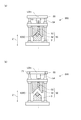
次に、第4の工程である離型工程S6について説明する。図7(a)及び図7(b)は、離型工程S6の説明図である。素材9及び成形型50がTgよりも低い温度、例えばTg−20℃になった時点でプレス及び冷却を停止する。図7(a)に示すように、まず上型53を上方向Z2に移動させて素材9(プリズム90)から離間させる。その後、図7(b)に示すように、胴型52を上方向Z2に移動させて素材9(プリズム90)から離間させる。これにより、離型工程S6において成形型50の型開きを行う際に、素材9(プリズム90)が上型53に貼り付くのを抑制することができる。
Next, the fourth step, the mold release step S6, will be described. FIG. 7A and FIG. 7B are explanatory views of the mold release step S6. The pressing and cooling are stopped when the
最後に、素材9(プリズム90)が載置された下型51を不図示の搬送装置で搬出した後、素材9(プリズム90)を下型51から取出し、図1(a)〜図1(c)に示すプリズム90を得る。
Finally, the
以上の工程を経て製造されたプリズム90は、図1(a)に示すように、プリズム90の非光学面Cに、基面C1に対して凹む凹部Rが形成される。即ち、図6(c)に示すプレス成形中の成形型50において、上型53は胴型52に対して突出した状態となっている。素材9は成形品毎にわずかながら重量(体積)にバラツキが生じるが、非光学面Cとなる一部分を押圧して凹部Rを形成することで、重量のバラツキを凹部Rの深さのバラツキとして吸収する。更に、非光学面Cにおける凹部Rの底面C2にヒケを集中させることができる。そのため、素材9の重量のバラツキがプリズム90の光学面A,A,Dの精度に影響を及ぼすことはない。即ち、プリズム90の光学面A,A,Dを高精度に形成することができる。このように、形成されるプリズム90の底面C2は、ヒケ誘導面であり、僅かに凹状に凹んでいる。ヒケによる底面C2の凹み量は、数μm程度である。
In the
凹部Rを構成する側壁面C3の仮想軸線L0の延びる方向である上下方向Zの高さH1について説明する。側壁面C3の高さH1は、素材9の重量のバラツキや、上型53の欠けを防止するエッジのR面取り、非光学面Cにバリが形成されるのを防止することなどを考慮して、0.05mm以上とすることが好ましい。逆に側壁面C3の高さH1が大きすぎると、三角プリズムの光学有効域や離型抵抗に影響を与えるため、側壁面C3の高さH1は5mm以下とすることが好ましい。即ち、側壁面C3の高さH1を0.05mm以上5mm以下とするのが好ましく、0.5mmとするのがより好ましい。
The height H1 in the vertical direction Z, which is the direction in which the imaginary axis L0 of the side wall surface C3 constituting the recess R extends, will be described. The height H1 of the side wall surface C3 takes into consideration the weight variation of the
成形型50においては、図6(c)に示す工程において、胴型52の面C1mに対して、プレス軸線L0mの延びる方向、即ち下方向Z1の上型53の押圧面C2mの突出量を、0.05mm以上5mm以下、例えば0.5mmとすればよい。
In the forming
仮想軸線L0と底面C2の法線L2とのなす角度θ、即ちプレス軸線L0mと押圧面C2mの法線L2mとの成す角度θの下限値について説明する。角度θは、押圧面C2mに対して垂直な光学面Am、Dmの離型性が確保できるよう、10度以上であることが好ましい。また、角度θが20度以上であればより好ましい。また、角度θが30度以上であれば更に好ましい。また、角度θが40度以上であれば更に好ましい。 The lower limit of the angle θ between the imaginary axis L0 and the normal L2 of the bottom surface C2, ie, the angle θ between the press axis L0m and the normal L2m of the pressing surface C2m, will be described. The angle θ is preferably 10 degrees or more so as to ensure releasability of the optical surfaces Am and Dm perpendicular to the pressing surface C2m. Is more preferably 20 degrees or more. Is more preferably 30 degrees or more. Is more preferably 40 degrees or more.
角度θの上限値について説明する。押圧面C2mのプレス軸線L0mの延びる方向への投影面積を確保できるよう、角度θは70度以下であることが好ましい。押圧面C2mのプレス軸線L0mの延びる上下方向Zへの投影面をプリズム90に対して十分大きくとることで、素材9に安定してプレス圧を伝達するともに、ヒケを確実に底面C2に誘導することを容易にしている。また、角度θが60度以下であればより好ましい。また、角度θが50度以下であれば更に好ましい。
The upper limit value of the angle θ will be described. The angle θ is preferably 70 degrees or less so as to ensure a projected area of the pressing surface C2m in the extending direction of the press axis L0m. By making the projection plane in the vertical direction Z where the pressing axis L0m of the pressing surface C2m extends sufficiently large with respect to the
以上、角度θは、10度以上70度以下であるのが好ましいが、下限値については、10度、20度、30度、40度と角度が大きくなるほど好ましい。また、上限値については、70度、60度、50度と角度が小さくなるほど好ましい。離型性及びプレス圧の観点から、角度θが45度であるのが最も好ましい。 As described above, the angle θ is preferably 10 degrees or more and 70 degrees or less, but the lower limit value is preferably 10 degrees, 20 degrees, 30 degrees, or 40 degrees as the angle is larger. Further, with respect to the upper limit value, it is preferable that the angle be as small as 70 degrees, 60 degrees, and 50 degrees. It is most preferable that the angle θ be 45 degrees in terms of releasability and press pressure.
また、プリズム90は、使用特性上、複数の光学面を有する。光学面及び非光学面が平面で構成されている場合、非光学面が少なくとも1つの光学面に対し直交することがある。上型を非光学面に対して垂直にプレスするよう成形型を構成した場合、非光学面に垂直な光学面を形成するためには、水平方向にスライドするスライド駒が必要である。
Further, the
これに対し、第1実施形態では、図6(c)に示すように、上型53を胴型52の面C1mの法線L1mに対して傾斜する方向に摺動させて、素材9をプレスするようにしている。このように、各成形面がプレス軸線L0mに対して傾斜しているため、水平方向にスライドするスライド駒は不要である。また、押圧面C2mで形成される底面C2をヒケ誘導面としても活用するため、新たにヒケを誘導するための機構を成形型50に設ける必要がない。この結果、成形型50は単純でコンパクトな構成となる。
On the other hand, in the first embodiment, as shown in FIG. 6C, the
本実施形態ではプリズム90として三角プリズムの場合について説明したが、これに限定するものではない。複数の光学面と、少なくとも1つの非光学面とを有するプリズムにおいて、本発明は適用可能である。そして、プリズムにおいて、非光学面が少なくとも1つの光学面に垂直であれば好適である。
In the present embodiment, the case of a triangular prism as the
[第2実施形態]
第2実施形態に係るプリズムを製造する具体的な方法について説明する。図8(a)は、第2実施形態におけるプリズム90Aの斜視図である。光学素子であるプリズム90Aは、双眼鏡やカメラ等の光学機器に装備される。プリズム90Aは、例えば三角プリズム2つを90度捻って接合した形状の4面プリズム(ポロプリズム)である。プリズム90Aの素材は、ガラスでもよいが、ガラスよりも軽量であり低コストである熱可塑性樹脂としている。
Second Embodiment
A specific method of manufacturing the prism according to the second embodiment will be described. FIG. 8A is a perspective view of a
プリズム90Aは、仮想軸線L0まわりに180度回転対称な形状である。図8(b)は、プリズム90Aを二分割する仮想軸線L0を含む仮想面P2に沿うプリズム90Aの断面図である。図8(c)は、仮想軸線L0の延びる方向に見たプリズム90Aの平面図である。
The
プリズム90Aは、光学面E、非光学面F、非光学面G及び光学面Hをそれぞれ2面ずつ有する。非光学面Gは、平面である基面G1と、基面G1に対して凹む凹部R2と、を有する。凹部R2は、ほぼ平面状の底面G2と、側壁面G3と、を含んでいる。光学面H,H同士のなす角は90度であり、隣接する光学面Eと光学面Hとのなす角は45度である。また、非光学面F及び底面G2と、光学面E,Hとのなす角は90度である。第2実施形態では、隣り合う複数の非光学面G,Gの各々に含まれる底面G2,G2同士が稜線を介して連続している。
The
なお、基面G1と底面G2とは平行である。よって、基面G1の法線L11と底面G2の法線L12とは平行である。即ち法線L11と法線L12とは同じ方向に延びている。仮想軸線L0と法線L11,L12とのなす角度をθとする。なお、仮想軸線L0と法線L11,L12とのなす角度には、合計すると180度となる2つの角度、即ち鋭角の角度と鈍角の角度とが存在するが、角度θは鋭角の角度とする。また、仮想軸線L0は、プリズム90Aが成形型内にあるときに成形型のプレス軸線と一致する線である。
The base surface G1 and the bottom surface G2 are parallel to each other. Therefore, the normal line L11 of the base surface G1 and the normal line L12 of the bottom surface G2 are parallel. That is, the normal line L11 and the normal line L12 extend in the same direction. The angle between the imaginary axis L0 and the normals L11 and L12 is θ. Note that there are two angles totaling 180 degrees between the imaginary axis L0 and the normal lines L11 and L12, that is, an acute angle and an obtuse angle, but the angle θ is an acute angle. . The virtual axis L0 is a line that coincides with the press axis of the mold when the
プリズム90Aを製造する製造システムは、成形型を除き、第1実施形態において説明した製造システムとほぼ同様である。即ち、第2実施形態における成形型が第1実施形態と異なる。図9は、第2実施形態における成形型50Aを切断したときの一対の切断片のうち一方を示す斜視図である。図9には、プレス軸線L0mを含む面であってキャビティCVを2分割する仮想面(図8(a)の仮想面P2に相当)で成形型50Aを切断して図示している。なお、成形型50AのキャビティCVにプリズム90Aが配置されている状態では、図8(a)に示す仮想軸線L0とプレス軸線L0mとは重なる。プレス装置の成形型50Aは、第1の型である下型51A、第2の型である胴型52A、及び第3の型である上型53Aからなるプリズム成形用の金型である。
The manufacturing system for manufacturing the
図10(a)は下型51Aを切断したときの一対の切断片のうち一方を示す斜視図である。図10(b)は胴型52Aを切断したときの一対の切断片のうち一方を示す斜視図である。図10(c)は上型53Aを切断したときの一対の切断片のうち一方を示す斜視図である。図10(a)〜図10(c)においても、図9と同様の仮想面で各型を切断して図示している。
FIG. 10A is a perspective view showing one of a pair of cut pieces when the
下型51Aは、図10(a)に示すように、プリズム90Aの光学面Eを形成する面である光学面Emと、プリズム90Aの非光学面Fを形成する面である非光学面Fmと、を有する。また、下型51Aは、第1実施形態と同様、当接面61及び摺接面65を有する。
The
胴型52Aは、図10(b)に示すように、プリズム90Aの光学面Hを形成する面である光学面Hmと、プリズム90Aの非光学面Gの一部である基面G1を形成する面G1mと、を有する。また、胴型52Aは、第1実施形態と同様、当接面62、摺接面64及び摺接面66を有する。
As shown in FIG. 10B, the
上型53Aは、プリズム90Aの非光学面Gの他部である凹部R2を形成するものであり、胴型52Aに対して上下方向Zに摺動自在である。上型53Aは、図10(c)に示すように、凹部R2の底面G2を形成する押圧面G2mと、押圧面G2mに連続する摺接面63と、を有する。押圧面G2mは、外周が直線及び円弧で形成されており、摺接面63を精度良く加工できる形状になっている。
The upper die 53A forms a recess R2 which is the other part of the non-optical surface G of the
図9に示すように、摺接面63,64,65,66は、第1実施形態と同様、プレス軸線L0mと平行な方向、即ち上下方向Zに延びる面である。下型51Aに対して胴型52Aを上下方向Zに移動させることにより、下型51Aの摺接面65と胴型52Aの摺接面66とが摺接する。また、胴型52Aに対して上型53Aを上下方向Zに移動させることにより、胴型52Aの摺接面64と上型53Aの摺接面63とが摺接する。当接面62は、当接面61と重なり合う形状に形成されている。
As shown in FIG. 9, the sliding contact surfaces 63, 64, 65 and 66 are surfaces extending in the direction parallel to the press axis L0m, that is, in the vertical direction Z, as in the first embodiment. By moving the
胴型52Aは、下型51Aの摺接面65に摺接して下型51Aに対して上下方向Zに摺動することにより、プレス軸線L0mに軸合わせがなされる。また、胴型52Aは、当接面62が下型51Aの当接面61に当接することで、上下方向Zの位置決めがなされる。上型53Aは、胴型52Aの摺接面64に摺接して胴型52Aに対して上下方向Zに摺動することにより、プレス軸線L0mに軸合わせがなされる。また、上型53Aを胴型52Aに対して摺動させることで、押圧面G2mを通じて素材にプレス圧を伝達し、各面Em,Fm,Gm,Hmの転写が行われる。
The
光学面Em,非光学面Fm,非光学面Gmの面G1m及び押圧面G2m,光学面Hmは、全てプレス軸線L0mに対して傾斜する傾斜面である。即ち、面G1m及び押圧面G2mは、摺接面63に対して傾斜する傾斜面である。また、胴型52A及び上型53Aは、面G1mと押圧面G2mとが平行となるように配置されている。即ち、面G1mの法線L11mと面G2mの法線L12mとは平行である。つまり、法線L11mと法線L12mとは同じ方向に延びている。プレス軸線L0mと法線L11m,L12mとの成す角度は、図8(b)に示す角度θと一致する。
The optical surface Em, the non-optical surface Fm, the surface G1m of the non-optical surface Gm, the pressing surface G2m, and the optical surface Hm are all inclined surfaces inclined with respect to the press axis L0m. That is, the surface G1m and the pressing surface G2m are inclined surfaces that are inclined with respect to the sliding
2つの押圧面G2m,G2mは、連続している。また押圧面G2mのプレス軸線L0mの延びる上下方向Zへの投影面は、プリズム90Aに対して十分大きくとられており、プレス工程において素材に安定してプレス圧を伝達するとともに、ヒケを確実に底面G2に誘導することを容易にしている。上型53Aで形成される押圧面G2mの法線L12mは、2面ともプレス軸線L0mに対して傾斜している。他の光学面Em、非光学面Fm、光学面Hmもプレス軸線L0mに対して傾斜してキャビティCVが形成される。
The two pressing surfaces G2m and G2m are continuous. The projection surface in the vertical direction Z in which the pressing axis L0m of the pressing surface G2m extends is sufficiently large with respect to the
なお、プリズム90Aを製造する製造方法の各工程は、第1実施形態と同様であるため、説明を省略する。第2実施形態においても、第1実施形態と同様、プレス成形により、内部歪みの小さいプリズム90Aが得られる。また、第1実施形態と同様の工程を経て製造されたプリズム90Aは、図8(a)に示すように、プリズム90Aの非光学面Gに、基面G1に対して凹む凹部R2が形成される。即ち、プレス成形中の成形型50Aにおいて、上型53Aは胴型52Aに対して突出した状態となっている。素材は成形品毎にわずかながら重量(体積)にバラツキが生じるが、非光学面Gとなる一部分を押圧して凹部R2を形成することで、重量のバラツキを凹部R2の深さのバラツキとして吸収する。更に、非光学面Gにおける凹部R2の底面G2にヒケを集中させることができる。そのため、素材の重量のバラツキがプリズム90Aの光学面E,Hの精度に影響を及ぼすことはない。即ち、プリズム90Aの光学面E,Hを高精度に形成することができる。このように、形成されるプリズム90Aの底面G2は、ヒケ誘導面であり、僅かに凹状に凹んでいる。ヒケによる底面G2の凹み量は、数μm程度である。
In addition, since each process of the manufacturing method which manufactures
凹部R2を構成する側壁面G3の仮想軸線L0の延びる方向である上下方向Zの高さH2について説明する。側壁面G3の高さH2は、素材の重量のバラツキや、上型53Aの欠けを防止するエッジのR面取り、非光学面Gにバリが形成されるのを防止することなどを考慮して、0.05mm以上とすることが好ましい。逆に側壁面G3の高さH2が大きすぎると、三角プリズムの光学有効域や離型抵抗に影響を与えるため、側壁面G3の高さH2は5mm以下とすることが好ましい。即ち、側壁面G3の高さH2を0.05mm以上5mm以下とするのが好ましく、0.5mmとするのがより好ましい。
The height H2 in the vertical direction Z, which is the direction in which the imaginary axis L0 of the side wall surface G3 constituting the recess R2 extends, will be described. The height H2 of the side wall surface G3 takes into consideration the weight variation of the material, R-chamfering of the edge to prevent the chipping of the
成形型50Aにおいては、胴型52Aの面G1mに対して、プレス軸線L0mの延びる方向、即ち下方向の上型53Aの押圧面G2mの突出量を、0.05mm以上5mm以下、例えば0.5mmとすればよい。
In the forming die 50A, the amount of protrusion of the pressing surface G2m of the
仮想軸線L0と底面G2の法線L12とのなす角度θ、即ちプレス軸線L0mと押圧面G2mの法線L12mとの成す角度θの下限値について説明する。角度θは、押圧面G2m及び押圧面G2mに対して垂直な光学面Em、Hmの離型性が確保できるよう、10度以上であることが好ましい。また、角度θが20度以上であればより好ましい。また、角度θが30度以上であれば更に好ましい。また、角度θが40度以上であれば更に好ましい。 The lower limit of the angle θ between the imaginary axis L0 and the normal L12 of the bottom surface G2, ie, the angle θ between the press axis L0m and the normal L12m of the pressing surface G2m, will be described. The angle θ is preferably 10 degrees or more so that the releasability of the optical surfaces Em and Hm perpendicular to the pressing surface G2m and the pressing surface G2m can be ensured. Is more preferably 20 degrees or more. Is more preferably 30 degrees or more. Is more preferably 40 degrees or more.
角度θの上限値について説明する。押圧面G2mのプレス軸線L0mの延びる方向への投影面積を確保できるよう、角度θは70度以下であることが好ましい。押圧面G2mのプレス軸線L0mの延びる上下方向Zへの投影面をプリズム90Aに対して十分大きくとることで、素材に安定してプレス圧を伝達するともに、ヒケを確実に底面G2に誘導することを容易にしている。また、角度θが60度以下であればより好ましい。また、角度θが50度以下であれば更に好ましい。
The upper limit value of the angle θ will be described. The angle θ is preferably 70 degrees or less so that the projected area of the pressing surface G2m in the extending direction of the press axis L0m can be secured. The projection surface in the vertical direction Z in which the pressing axis L0m of the pressing surface G2m extends is made sufficiently large with respect to the
以上、角度θは、10度以上70度以下であるのが好ましいが、下限値については、10度、20度、30度、40度と角度が大きくなるほど好ましい。また、上限値については、70度、60度、50度と角度が小さくなるほど好ましい。離型性及びプレス圧の観点から、角度θが45度であるのが最も好ましい。 As described above, the angle θ is preferably 10 degrees or more and 70 degrees or less, but the lower limit value is preferably 10 degrees, 20 degrees, 30 degrees, or 40 degrees as the angle is larger. Further, with respect to the upper limit value, it is preferable that the angle be as small as 70 degrees, 60 degrees, and 50 degrees. It is most preferable that the angle θ be 45 degrees in terms of releasability and press pressure.
また、第2実施形態では、上型53Aを胴型52Aの面G1mの法線L11mに対して傾斜する方向に摺動させて、素材をプレスするようにしている。各成形面がプレス軸線L0mに対して傾斜しているため、水平方向にスライドするスライド駒は不要である。また、押圧面G2mで形成される底面G2をヒケ誘導面としても活用するため、新たにヒケを誘導するための機構を成形型50Aに設ける必要がない。この結果、成形型50Aは単純でコンパクトな構成となる。
In the second embodiment, the
第2実施形態では、隣り合う複数の非光学面G,Gの各々に含まれる底面同士G2,G2が、仮想軸線L0が通過する稜線で連続している。成形型50Aにおいては、押圧面同士G2m,G2mが、プレス軸線L0mが通過する稜線で連続している。押圧面G2m,G2mのプレス軸線L0mの延びる上下方向Zへの投影面は、プリズム90Aに対して十分大きくとられており、プレス工程において素材に安定してプレス圧を伝達するとともに、ヒケを確実に底面G2,G2に誘導することを容易にしている。
In the second embodiment, the bottom surfaces G2 and G2 included in each of the plurality of non-optical surfaces G and G adjacent to each other are continuous at a ridge line through which the imaginary axis L0 passes. In the forming die 50A, the pressing surfaces G2m and G2m are continuous at a ridge line through which the press axis L0m passes. The projection surface in the vertical direction Z in which the pressing axis L0m of the pressing surfaces G2m and G2m extends is sufficiently large relative to the
なお、押圧面G2m、G2mの法線L12m,L12mはプレス軸線L0mに対して2面とも45度傾斜しているため、凹部R2を形成する側壁面G3は非光学面Gの基面G1に対して45度傾斜する。また上型53Aの摺接面63の一部が側壁面G3として転写されるので、対向する側壁面同士G3,G3は平行になる。
Since the normals L12m and L12m of the pressing surfaces G2m and G2m are both 45 degrees inclined with respect to the press axis L0m, the side wall surface G3 forming the recess R2 with respect to the base surface G1 of the non-optical surface G Tilt 45 degrees. Further, since a part of the sliding
[第3実施形態]
次に、第1実施形態あるいは第2実施形態のプリズムを備えた光学機器の実施形態を説明する。ここでは、光学機器として双眼鏡の例を示す。
図11は、本発明の実施形態である双眼鏡の外観を示す斜視図である。一点鎖線で示すOLは左の対物光学系の光軸、ORは右の対物光学系の光軸である。ELは左の接眼光学系の光軸であり、ERは右の接眼光学系の光軸である。ここでいう左と右は、双眼鏡を使用する使用者の左眼と右眼に対応している。
また、図11は、左右の対物光学系の光軸OL、ORの間隔と、左右の接眼光学系の光軸EL、ERの間隔とが同一になっている状態を表している。
Third Embodiment
Next, an embodiment of an optical apparatus provided with the prism of the first embodiment or the second embodiment will be described. Here, an example of binoculars is shown as an optical instrument.
FIG. 11 is a perspective view showing an appearance of binoculars according to an embodiment of the present invention. OL shown by a dashed dotted line is an optical axis of the left objective optical system, and OR is an optical axis of the right objective optical system. EL is the optical axis of the left eyepiece optical system, and ER is the optical axis of the right eyepiece optical system. The left and right here correspond to the left and right eyes of the user who uses binoculars.
Further, FIG. 11 shows a state in which the distance between the optical axes OL and OR of the left and right objective optical systems is equal to the distance between the optical axes EL and ER of the left and right eyepiece optical systems.
図12は図11の状態の双眼鏡について、対物光学系の左の光軸OLと接眼光学系の左の光軸ELを共に含む平面で切った断面を示している。
まず、双眼鏡に設けられた左右の光学系の構成について説明する。L1L、L1Rは左右の保護ガラスである。L2L、L2Rは左右の前玉レンズ、L3L、L3Rは左右の固定レンズ、L4L、L4Rは左右の対物光学系の一部又は全部よりなる左右の防振レンズとしての左右の可動レンズである。L2L、L3L、L4Lは左の対物光学系を構成し、L2R、L3R、L4Rは右の対物光学系を構成している。これらにより左右の対物光学系が構成される。
FIG. 12 shows a cross section taken along a plane including both the left optical axis OL of the objective optical system and the left optical axis EL of the eyepiece optical system for the binoculars in the state of FIG.
First, the configuration of the left and right optical systems provided in the binoculars will be described. L1L and L1R are left and right protective glass. L2L and L2R are left and right front lens lenses, L3L and L3R are left and right fixed lenses, and L4L and L4R are left and right movable lenses as left and right anti-vibration lenses consisting of part or all of the left and right objective optical systems. L2L, L3L and L4L constitute a left objective optical system, and L2R, L3R and L4R constitute a right objective optical system. These constitute the left and right objective optical systems.
L5L、L5Rは左右の正立光学系を構成する左右のポロII型プリズムである。L6L、L6Rは左右の接眼光学系を構成する左右の接眼レンズである。左の接眼レンズL6Lの光軸は左の接眼光学系の光軸ELに一致し、右の接眼レンズL6Rの光軸は右の接眼光学系の光軸ERに一致する。以上により、左右の観察光学系が構成されている。尚、右側の光学系に関するL2R、L3R、L4R、L5R、L6Rは、図11および図12では見えない位置にあるため、図示されていない。 L5L and L5R are left and right polo-II type prisms that constitute left and right erecting optical systems. L6L and L6R are left and right eyepiece lenses constituting the left and right eyepiece optical systems. The optical axis of the left eyepiece L6L coincides with the optical axis EL of the left eyepiece optical system, and the optical axis of the right eyepiece L6R coincides with the optical axis ER of the right eyepiece optical system. Thus, the left and right observation optical systems are configured. Note that L2R, L3R, L4R, L5R, and L6R related to the optical system on the right side are not shown because they are at positions not visible in FIG. 11 and FIG.
本実施形態の双眼鏡では、凹部にヒケを誘導したため極めて高い形状精度の光学面を備えたプリズムを、左右の正立光学系のポロII型プリズムであるL5LとL5Rに用いた。そのため、本実施形態の双眼鏡は、左右の正立光学系の精度が高く、しかも均一であり、極めて高性能である。 In the binoculars of the present embodiment, since the dips are guided to the concave portions, a prism provided with an optical surface with extremely high shape accuracy is used for L5L and L5R which are Polo II type prisms of right and left erecting optical systems. Therefore, in the binoculars of the present embodiment, the precision of the right and left erecting optical systems is high, uniform, and extremely high-performance.
なお、本発明は、以上説明した実施形態に限定されるものではなく、本発明の技術的思想内で多くの変形が可能である。また、実施形態に記載された効果は、本発明から生じる最も好適な効果を列挙したに過ぎず、本発明による効果は、実施形態に記載されたものに限定されない。 The present invention is not limited to the embodiments described above, and many modifications can be made within the technical concept of the present invention. In addition, the effects described in the embodiment only list the most preferable effects arising from the present invention, and the effects according to the present invention are not limited to those described in the embodiment.
上述の実施形態では、熱可塑性樹脂がCOP樹脂である場合について説明したが、これに限定するものではない。熱可塑性樹脂が、例えばPC(ポリカーボネート)樹脂やPMMA(ポリメチルメタクリレート)樹脂、COC(シクロオレフィンコポリマー)樹脂、MS(ポリメタクリルスチレン)樹脂などの材料でもよい。また、その他の樹脂でも熱可塑性樹脂であり、プリズムとして使用可能なものであれば、いかなる熱可塑性樹脂であってもよい。 Although the above-mentioned embodiment explained the case where thermoplastics were COP resin, it does not limit to this. The thermoplastic resin may be, for example, a material such as PC (polycarbonate) resin, PMMA (polymethyl methacrylate) resin, COC (cycloolefin copolymer) resin, MS (polymethacrylic styrene) resin and the like. In addition, any other resin may be a thermoplastic resin and any thermoplastic resin may be used as long as it can be used as a prism.
また、上述の第1実施形態では、下型51及び胴型52と上型53との間に温度差を設けて冷却することで、非光学面である押圧面C2mにヒケを誘導する場合について説明したが、これに限定するものではない。例えば、成形型50の冷却中に上型53を離間させて押圧面C2mを断熱かつ非拘束状態とし、ヒケを誘導させてもよい。第2実施形態についても同様である。
Further, in the above-described first embodiment, a case where a sink is induced to the pressing surface C2m which is a non-optical surface by providing a temperature difference between the
9…素材、50…成形型、51…下型(第1の型)、52…胴型(第2の型)、53…上型(第3の型)、90…プリズム、A…光学面、C…非光学面、C1…基面、C2…底面、L0…仮想軸線、L0m…プレス軸線、R…凹部 9 material, 50 mold, 51 lower mold (first mold) 52 barrel type (second mold) 53 upper mold (third mold) 90 prism A optical surface , C: non-optical surface, C1: base surface, C2: bottom surface, L0: imaginary axis, L0 m: press axis, R: recess
Claims (17)
第1の型と、前記非光学面の基面を形成する面を有する第2の型とで素材を挟み込む第1の工程と、
前記基面に対して凹む凹部を形成する第3の型を、前記基面を形成する面に対し前記素材の側に突出させて、前記素材を押圧する第2の工程と、
前記素材を冷却する第3の工程と、を備える、
ことを特徴とするプリズムの製造方法。 A method of manufacturing a prism having an optical surface and a non-optical surface, comprising:
A first step of sandwiching a material with a first mold and a second mold having a surface forming a base surface of the non-optical surface;
A second step of pressing a material by causing a third die for forming a recess recessed with respect to the base surface to protrude to the side of the material with respect to a surface forming the base surface;
And a third step of cooling the material.
A method of manufacturing a prism characterized in that.
ことを特徴とする請求項1に記載のプリズムの製造方法。 In the third step, in the process of cooling the material, a temperature difference is provided such that the temperature of the third mold is higher than the temperatures of the first mold and the second mold.
The method of manufacturing a prism according to claim 1,
ことを特徴とする請求項1又は2に記載のプリズムの製造方法。 In the second step, the third mold is slid relative to the second mold in a direction inclined with respect to the direction of the normal to the surface forming the base surface to press the material. Do,
A method of manufacturing a prism according to claim 1 or 2, characterized in that:
前記第2の工程において、前記傾斜面を、前記基面を形成する面に対して平行な姿勢で、前記摺接面の一部及び前記傾斜面の全部を、前記基面を形成する面に対し前記素材の側に突出させて、前記素材を押圧する、
ことを特徴とする請求項3に記載のプリズムの製造方法。 The third mold has a sliding contact surface in sliding contact with the second mold, and an inclined surface which is inclined with respect to the sliding contact surface,
In the second step, the inclined surface is in a posture parallel to the surface forming the base surface, and a part of the sliding surface and the entire inclined surface are formed on the surface forming the base surface. The material is projected to the side of the material, and the material is pressed,
The method of manufacturing a prism according to claim 3,
前記第2の工程において、前記傾斜面を、前記光学面を形成する面に対して垂直な姿勢として、前記素材を押圧する、
ことを特徴とする請求項4に記載のプリズムの製造方法。 The first mold or the second mold has a surface forming the optical surface,
In the second step, the material is pressed with the inclined surface in a posture perpendicular to the surface forming the optical surface.
5. The method of manufacturing a prism according to claim 4, wherein
前記第4の工程において、前記第3の型を前記素材から離間させた後に、前記第2の型を前記素材から離間させる、
ことを特徴とする請求項1乃至5のいずれか1項に記載のプリズムの製造方法。 The method further comprises a fourth step of performing mold opening of the first mold, the second mold and the third mold,
In the fourth step, after the third mold is separated from the material, the second mold is separated from the material.
A method of manufacturing a prism according to any one of claims 1 to 5, characterized in that.
ことを特徴とする請求項1乃至6のいずれか1項に記載のプリズムの製造方法。 The material is a thermoplastic resin,
A method of manufacturing a prism according to any one of claims 1 to 6, characterized in that:
前記非光学面は、基面と、前記基面に対して凹む、底面及び側壁面を含む凹部と、を有する、
ことを特徴とするプリズム。 It has an optical surface and a non-optical surface,
The non-optical surface has a base surface and a recess that is recessed with respect to the base surface, including a bottom surface and a sidewall surface.
A prism characterized by that.
ことを特徴とする請求項8に記載のプリズム。 The bottom surface is a concave sinking guide surface,
The prism according to claim 8, characterized in that:
ことを特徴とする請求項8又は9に記載のプリズム。 The side wall surface extends in a direction inclined with respect to the normal to the bottom surface
The prism according to claim 8 or 9, characterized in that:
ことを特徴とする請求項10に記載のプリズム。 The length of the side wall surface is 0.05 mm or more and 5 mm or less.
The prism according to claim 10, characterized in that:
ことを特徴とする請求項10又は11に記載のプリズム。 The angle between the normal line and the side wall surface is 10 degrees or more and 70 degrees or less.
The prism according to claim 10 or 11, characterized in that:
前記複数の非光学面の各々に含まれる前記底面同士が連続している、
ことを特徴とする請求項8乃至12のいずれか1項に記載のプリズム。 Comprising a plurality of adjacent non-optical surfaces,
The bottom surfaces included in each of the plurality of non-optical surfaces are continuous,
A prism according to any one of claims 8 to 12, characterized in that.
ことを特徴とする請求項8乃至13のいずれか1項に記載のプリズム。 The bottom surface is perpendicular to the optical surface,
The prism according to any one of claims 8 to 13, characterized in that:
ことを特徴とする請求項8乃至14のいずれか1項に記載のプリズム。 The material of the prism is a thermoplastic resin,
The prism according to any one of claims 8 to 14, characterized in that:
複数のレンズを含む左右の光学系と、
を有することを特徴とする双眼鏡。 The prism according to any one of claims 8 to 15,
Left and right optical systems including multiple lenses,
Binoculars characterized by having.
第1の型と、
非光学面の基面を成形する面を有し、前記第1の型と共に素材が配置される空間を形成する第2の型と、
前記第2の型に対して前記空間の側に突出するよう前記第2の型に対して摺動自在であり、前記基面に対して凹む凹部を形成する第3の型と、を備える、
ことを特徴とする成形型。 A forming die for forming a prism by press forming,
The first type,
A second mold having a surface for molding a base surface of the non-optical surface and forming a space in which the material is disposed together with the first mold;
And a third mold which is slidable with respect to the second mold so as to protrude toward the space with respect to the second mold and which forms a recess recessed with respect to the base surface.
A mold characterized by
Priority Applications (1)
| Application Number | Priority Date | Filing Date | Title |
|---|---|---|---|
| US16/127,467 US10974475B2 (en) | 2017-09-22 | 2018-09-11 | Prism, forming mold, and method of producing prism |
Applications Claiming Priority (2)
| Application Number | Priority Date | Filing Date | Title |
|---|---|---|---|
| JP2017183030 | 2017-09-22 | ||
| JP2017183030 | 2017-09-22 |
Publications (1)
| Publication Number | Publication Date |
|---|---|
| JP2019059228A true JP2019059228A (en) | 2019-04-18 |
Family
ID=66176969
Family Applications (1)
| Application Number | Title | Priority Date | Filing Date |
|---|---|---|---|
| JP2018157415A Pending JP2019059228A (en) | 2017-09-22 | 2018-08-24 | Production method of prism, prism, and mold |
Country Status (1)
| Country | Link |
|---|---|
| JP (1) | JP2019059228A (en) |
Cited By (1)
| Publication number | Priority date | Publication date | Assignee | Title |
|---|---|---|---|---|
| CN115592508A (en) * | 2022-10-20 | 2023-01-13 | 福建福胜达智能科技有限公司(Cn) | An optical prism processing and positioning device |
-
2018
- 2018-08-24 JP JP2018157415A patent/JP2019059228A/en active Pending
Cited By (1)
| Publication number | Priority date | Publication date | Assignee | Title |
|---|---|---|---|---|
| CN115592508A (en) * | 2022-10-20 | 2023-01-13 | 福建福胜达智能科技有限公司(Cn) | An optical prism processing and positioning device |
Similar Documents
| Publication | Publication Date | Title |
|---|---|---|
| US7106528B2 (en) | Method and apparatus for manufacturing large double-sided curved Fresnel lens | |
| JPH10101347A (en) | Device for injection-molding optical parts and injection-molding method | |
| KR20060131632A (en) | Method for manufacturing optical unit, optical unit and molding apparatus | |
| JP6739131B2 (en) | Mold for molding optical component made of glass and method for manufacturing optical component made of glass using the mold | |
| US5822134A (en) | Optical lens and mold for molding the same | |
| US10974475B2 (en) | Prism, forming mold, and method of producing prism | |
| US20100242544A1 (en) | Optical lens forming mold | |
| JP2019059228A (en) | Production method of prism, prism, and mold | |
| JP5864873B2 (en) | Plastic molding product molding method, plastic molding system, optical element by plastic molding system | |
| JPH0471853B2 (en) | ||
| JP2006281765A (en) | Method and apparatus for improving surface accuracy of optical element | |
| JP2007022905A (en) | Optical element device manufacturing method, optical element device, and molding apparatus | |
| EP3941728A1 (en) | Mould pair having alignment surfaces | |
| JP2005193653A (en) | Optical component manufacturing method, manufacturing apparatus, and optical component | |
| JPH01164738A (en) | Optical element molding equipment | |
| JP2008230005A (en) | Plastic lens molding method and lens preform | |
| JP4289716B2 (en) | Glass element molding method | |
| JP2002283352A (en) | Manufacturing method of plastic optical element | |
| JP2012076452A (en) | Method for manufacturing optical component and optical component manufacturing device | |
| JP4563942B2 (en) | Molding method of thermoplastic material | |
| JP2010143129A (en) | Method for molding resin lens | |
| JP6503761B2 (en) | Method of manufacturing optical element and mold | |
| JP2017080927A (en) | Molding and manufacturing method for penta roof prism, molding die, and molded article | |
| JP2020104301A (en) | Resin part and its manufacturing method | |
| JP2013035151A (en) | Method for manufacturing optical element and optical element |
Legal Events
| Date | Code | Title | Description |
|---|---|---|---|
| RD02 | Notification of acceptance of power of attorney |
Free format text: JAPANESE INTERMEDIATE CODE: A7422 Effective date: 20200206 |
|
| RD04 | Notification of resignation of power of attorney |
Free format text: JAPANESE INTERMEDIATE CODE: A7424 Effective date: 20200207 |