JP2019060184A - Excavation site monitoring device - Google Patents
Excavation site monitoring device Download PDFInfo
- Publication number
- JP2019060184A JP2019060184A JP2017187271A JP2017187271A JP2019060184A JP 2019060184 A JP2019060184 A JP 2019060184A JP 2017187271 A JP2017187271 A JP 2017187271A JP 2017187271 A JP2017187271 A JP 2017187271A JP 2019060184 A JP2019060184 A JP 2019060184A
- Authority
- JP
- Japan
- Prior art keywords
- excavator
- video camera
- moving image
- site monitoring
- frames
- Prior art date
- Legal status (The legal status is an assumption and is not a legal conclusion. Google has not performed a legal analysis and makes no representation as to the accuracy of the status listed.)
- Pending
Links
- 238000009412 basement excavation Methods 0.000 title claims abstract description 33
- 238000012806 monitoring device Methods 0.000 title claims abstract description 10
- 238000012545 processing Methods 0.000 claims abstract description 40
- 238000005070 sampling Methods 0.000 claims abstract description 17
- 238000012544 monitoring process Methods 0.000 claims description 30
- 238000005553 drilling Methods 0.000 claims description 22
- 210000003128 head Anatomy 0.000 description 7
- 230000001133 acceleration Effects 0.000 description 6
- 238000003384 imaging method Methods 0.000 description 6
- 238000000034 method Methods 0.000 description 5
- 238000005516 engineering process Methods 0.000 description 3
- 239000000284 extract Substances 0.000 description 3
- 238000009434 installation Methods 0.000 description 3
- 238000004891 communication Methods 0.000 description 2
- 230000006835 compression Effects 0.000 description 2
- 238000007906 compression Methods 0.000 description 2
- 230000007423 decrease Effects 0.000 description 2
- 230000010355 oscillation Effects 0.000 description 2
- 238000012986 modification Methods 0.000 description 1
- 230000004048 modification Effects 0.000 description 1
- 238000003825 pressing Methods 0.000 description 1
- 239000011435 rock Substances 0.000 description 1
Images



Landscapes
- Excavating Of Shafts Or Tunnels (AREA)
Abstract
Description
この発明は、掘削現場監視装置に関する。 The present invention relates to a drilling site monitoring device.
トンネル等の掘削現場においては、掘削直後の切羽を記録するために、デジタルカメラによる撮影が行われているが、デジタルカメラでは画角が狭く切羽全体の撮影には時間が掛かる。この問題を解消するために、掘削機にデジタルカメラを設置して撮影をコンピュータで制御する技術が開発されている(たとえば、特許文献1参照)。 At a drilling site such as a tunnel, shooting with a digital camera is performed to record a face immediately after drilling, but with a digital camera, the angle of view is narrow and it takes time to shoot the entire face. In order to solve this problem, a technology has been developed in which a digital camera is installed in an excavator and a computer is used to control imaging (see, for example, Patent Document 1).
しかしながら、従来装置では、掘削後の切羽の撮影は可能であるが、静止画像のみしか撮影できず、掘削機で切羽を掘削している最中におけるトンネル内の現場状況の監視には不向きである。そこで、従来装置のデジタルカメラをビデオカメラに交換することも考えられるが、掘削機が切羽を掘削中している最中では、掘削機の振動によってビデオカメラも振動するので、撮影した動画もぶれてしまう。 However, with the conventional device, although it is possible to capture the face after excavating, only still images can be taken, and it is not suitable for monitoring the site condition in the tunnel while excavating the face with the excavator . Therefore, it is conceivable to replace the digital camera of the conventional device with a video camera, but while the excavator is digging the face, the video camera also vibrates due to the vibration of the excavator, so the captured moving image is also blurred. It will
撮影した動画は、モニタで監視者が確認するのであるが、ぶれた動画を見続けると監視者の目が非常に疲れるため、監視者の負担が大きくなる。動画を処理してぶれを補正する処理を行うことも考えられるが、高度な技術が要求されコストが嵩んでしまう。また、ビデオカメラを掘削機ではなく、他所に固定的に設ければ、動画のぶれを解消できるが、そうすると、掘削が進んで掘削機が進むたびにビデオカメラの位置も掘削機が進んだ分だけ移動させる盛り替えが必要となり、今度は現場作業者の負担が大きくなる。 The watcher confirms the captured moving image on the monitor, but if the watched moving image continues to be watched, the watcher's eyes become very tired and the burden on the watcher increases. It is conceivable to process moving pictures to correct blurring, but this requires high-level technology and increases costs. In addition, if the video camera is not fixed at the drilling machine but fixedly installed at another place, it is possible to eliminate the blurring of the moving image, but then the position of the video camera is also the minute the drilling machine is advanced each time the drilling is advanced. It will be necessary to make changes to move only this time, and this will increase the burden on site workers.
そこで、本発明は、簡単かつ安価であって、現場作業者に負担をかけずに監視者の疲労も軽減できる掘削現場監視装置の提供を目的とする。 Therefore, an object of the present invention is to provide a digging site monitoring apparatus that is simple and inexpensive, and can reduce the fatigue of a supervisor without burdening the site worker.
本発明の掘削現場監視装置は、掘削機に設けられて掘削機が掘削する切羽を撮影するビデオカメラと、ビデオカメラが撮影した動画のコマ数を間引く処理を行って表示装置に処理済動画を出力する処理部とを備えて構成される。このように構成された掘削現場監視装置では、ビデオカメラが掘削機の振動によって振動して、撮影された動画にぶれがあっても処理済動画ではぶれの速度が低下する。また、掘削機にビデオカメラが設置されるので、現場作業者がわざわざ掘削機の位置に合わせてビデオカメラの位置を盛り替える作業をせずに済む。さらに、ビデオカメラが撮影した動画のコマを間引く処理を行うだけでよいので、動画のぶれを補正する画像処理等の高度な技術が要求されず機器も安価で済む。また、掘削中、掘削前後を問わず切羽の撮影が可能であるから、切羽を解析するための動画が得られて、切羽の解析が可能となる。 The drilling site monitoring apparatus according to the present invention performs processing to thin out the processed moving image by performing processing for thinning out the number of frames of the moving image captured by the video camera and a video camera provided in an excavator and capturing a face that is excavated by the excavator. And an output processing unit. In the excavation site monitoring apparatus configured as described above, the video camera vibrates due to the vibration of the excavator, and the blurring speed of the processed moving image decreases even if the captured moving image has blurring. In addition, since the video camera is installed in the excavator, the site worker does not have to work to reposition the video camera according to the position of the excavator. Furthermore, since it is only necessary to thin out the frames of the moving image captured by the video camera, advanced techniques such as image processing for correcting the blurring of the moving image are not required, and the cost of the apparatus is also low. In addition, since it is possible to photograph the face during or after the excavation during the excavation, a moving image for analyzing the face is obtained, and the analysis of the face becomes possible.
また、掘削現場監視装置における処理部は、ビデオカメラが撮影した動画から掘削機の振動周期の整数倍の時間毎に撮影されたコマを抽出して、その他のコマを間引くようにしてもよい。このように処理すれば、ぶれが軽減された処理済動画が得られる。 In addition, the processing unit in the excavation site monitoring apparatus may extract frames captured every integral multiple of the vibration cycle of the excavator from the moving image captured by the video camera and thin the other frames. By processing in this way, a processed moving image with reduced blurring can be obtained.
さらに、本発明の他の掘削現場監視装置は、掘削機に設けられて所定のサンプリング周期で掘削機が掘削する切羽を撮影するビデオカメラを備え、サンプリング周期が掘削機の振動周期の整数倍の時間に設定されている。このように構成された掘削現場監視装置によれば、ぶれが軽減された動画を撮影できるので、動画を閲覧する監視者の疲労が軽減される。また、掘削機にビデオカメラが設置されるので、現場作業者がわざわざ掘削機の位置に合わせてビデオカメラの位置を盛り替える作業をせずに済む。さらに、ビデオカメラのサンプリング周期を掘削機の振動周期の整数倍の時間に設定するだけでよいので、動画のぶれを補正する画像処理等の高度な技術が要求されず機器も安価で済む。 Furthermore, another excavation site monitoring apparatus according to the present invention includes a video camera provided in the excavator for photographing a face to be excavated by the excavator at a predetermined sampling cycle, and the sampling cycle is an integral multiple of the oscillation cycle of the excavator. The time is set. According to the excavation site monitoring device configured as described above, since a moving image with reduced shake can be taken, fatigue of a monitoring person viewing the moving image is reduced. In addition, since the video camera is installed in the excavator, the site worker does not have to work to reposition the video camera according to the position of the excavator. Furthermore, since it is only necessary to set the sampling cycle of the video camera to a time that is an integral multiple of the vibration cycle of the excavator, advanced techniques such as image processing for correcting motion blur are not required, and the equipment is inexpensive.
そして、掘削現場監視装置が複数の他のビデオカメラを備えて掘削機の全周囲を撮影できるようにしてもよい。このようにすると、掘削機を移動操作する操作者が表示装置で掘削機の周囲を確認でき、安全に掘削機を移動させ得る。 The drilling site surveillance device may then be equipped with a plurality of other video cameras so that the entire perimeter of the excavator can be photographed. In this way, the operator moving the excavator can check the periphery of the excavator on the display device, and the excavator can be moved safely.
よって、本発明の掘削現場監視装置によれば、簡単かつ安価であって、現場作業者に負担をかけずに監視者の疲労も軽減できる。 Therefore, according to the excavation site monitoring apparatus of the present invention, it is simple and inexpensive, and it is possible to reduce the fatigue of the observer without burdening the site workers.
以下、図に示した実施の形態に基づき、本発明を説明する。なお、以下に説明する各実施の形態の掘削現場監視装置において共通する構成については同じ符号を付し、説明の重複を避けるために、一の実施の形態の掘削現場監視装置の説明において説明した構成については他の実施の形態の掘削現場監視装置における説明では詳細な説明を省略する。 Hereinafter, the present invention will be described based on the embodiments shown in the drawings. The same reference numerals are given to the common configuration in the excavation site monitoring apparatus according to each embodiment described below, and the same has been described in the explanation of the excavation site monitoring apparatus according to one embodiment to avoid duplication of the description. About a structure, detailed description is abbreviate | omitted by description in the excavation site monitoring apparatus of other embodiment.
<第一の実施の形態>
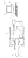
第一の実施の形態における掘削現場監視装置1は、図1に示すように、掘削機Eに設けられて掘削機Eが掘削する切羽Fを撮影するビデオカメラ2と、ビデオカメラ2が撮影した動画を処理する処理部3とを備えており、処理部3で処理した処理済動画を表示装置4へ出力する。
First Embodiment
The excavation site monitoring apparatus 1 according to the first embodiment is, as shown in FIG. 1, a
以下、掘削現場監視装置1の各部について詳細に説明する。まず、掘削現場監視装置1が適用される掘削機Eは、本例では、クローラを備えた走行体Wと、走行体Wに対して左右方向への旋回と上下方向への俯仰とを可能に取付けたブームBと、ブームBの先端に装着されて図外のモータによって回転駆動されるカッタヘッドCとを備えた自由断面掘削機とされている。 Hereinafter, each part of the excavation site monitoring apparatus 1 will be described in detail. First, the excavator E to which the excavation site monitoring apparatus 1 is applied, in this example, enables the traveling body W provided with crawlers, turning in the lateral direction and raising and lowering in the vertical direction with respect to the traveling body W It is a free cross-section excavator equipped with a boom B attached and a cutter head C attached to the tip of the boom B and rotationally driven by a motor (not shown).
このように構成された掘削機Eは、カッタヘッドCを図外のモータで回転駆動しつつ、ブームBを駆動してカッタヘッドCを切羽Fの掘削したい位置へ配置するととともにカッタヘッドCを略一定の押圧力で切羽Fに押し付けて切羽Fにおける岩盤を掘削する。 The excavator E configured in this way drives the boom B to rotate the cutter head C with a motor (not shown) and places the cutter head C at a position where digging of the cutting face F is desired. The rock face of the face F is excavated by pressing the face F with a constant pressure.
ビデオカメラ2は、図示はしないが、CCD(電荷結合素子)等の画像素子、レンズ(図示せず)、焦点調節部(図示せず)を備えており、本例では、切羽Fの撮影を可能とするため、走行体Wに起立させたポールPに取付けられて掘削機Eの前方を撮影範囲としている。なお、ビデオカメラ2の構成は、動画の撮影が可能であれば任意に変更でき、また、ビデオカメラ2の掘削機Eへの設置に関する構造も前記したところに限定されず、任意に変更でき、ビデオカメラ2をブームBに設置してもよい。
Although not shown, the
処理部3は、ビデオカメラ2と信号線5で接続されており、ビデオカメラ2が撮影した動画のコマ数を間引く処理を行う。なお、ビデオカメラ2と処理部3とは、無線通信で通信を行ってもよい。具体的には、処理部3は、ビデオカメラ2が所定のフレームレートで撮影した動画のコマから予め決められたコマ数毎のコマだけを抽出して、表示装置4へ出力する。図2に示したところでは、処理部3は、撮影された動画のコマa1,a2,a3・・・・anのうち、先頭のコマa1から3つおきにコマa4,a7,a10・・・を抽出して、表示装置4へ出力している。処理部3は、1+3m番目(mは、0と正の整数)のコマを抽出して、これを処理済動画として表示装置4へ出力する。
The
処理部3は、ビデオカメラ2が撮影した動画データを取り込み、抽出したコマを一纏めにした所定時間分の処理済動画のファイルを生成して、表示装置4へ出力してもよいし、ビデオカメラ2が撮影した動画データから決められたコマを順次抽出して、当該コマのデータを表示装置4へ順次送信するようにしてもよい。監視者が処理済動画を掘削現場の切羽Fの状況を監視する用途で使用する場合、ビデオカメラ2が掘削現場を撮影した時間からさほどの遅滞なく閲覧できるように前記所定時間を設定するとよい。処理済動画の用途によって、一纏めにされる処理済動画の長さである前記所定時間は、任意に設定できる。なお、処理済動画のファイルを生成する場合、動画の圧縮形式は、任意であり、表示装置4で復元可能な圧縮形式であればよい。
The
表示装置4は、具体的には、端末4aとモニタ4bとを備えており、処理部3と端末4aとが信号線6で接続されている。なお、処理部3と表示装置4は、無線通信で通信を行ってもよい。表示装置4は、処理部3で処理した処理済動画のデータを端末4aで受け取ると、モニタ4bに処理済動画を表示させる。処理済動画は、ビデオカメラ2で撮影した動画のコマ数が間引かれた動画となっている。
Specifically, the
そのため、表示装置4のモニタ4bには、まず、先頭のコマa1がコマを間引いた数に相当する時間のあいだ表示され、次に、4番目のコマa4がコマを間引いた数に相当する時間のあいだ表示され、つづいて、7番目のコマa7がコマを間引いた数に相当する時間のあいだ表示される。
Therefore, on the
掘削機Eが切羽Fを掘削している最中は、カッタヘッドCを駆動するモータの振動と、カッタヘッドCが切羽Fから受ける抵抗によって発生する振動がブームBを介して走行体Wにも伝達される。よって、掘削機Eが切羽Fを掘削中である場合、ビデオカメラ2も振動して、ビデオカメラ2によって撮影された動画はこの振動の影響でぶれる。このようにビデオカメラ2が激しく振動して撮影された動画にぶれがあっても、モニタ4bには、処理済動画のコマが順次静止画像のように表示され、動画のぶれの速度が見掛け上低下したかのように映し出される。よって、表示装置4のモニタ4bを見る監視者の目の疲労が軽減される。
While the drilling machine E is digging the face F, the vibration of the motor for driving the cutter head C and the vibration generated by the resistance received from the face F by the cutter head C are also transmitted to the traveling body W via the boom B. It is transmitted. Therefore, when the excavator E is digging the face F, the
このように、第一の実施の形態の掘削現場監視装置1は、掘削機Eに設けられて掘削機Eが掘削する切羽Fを撮影するビデオカメラ2と、ビデオカメラ2が撮影した動画のコマ数を間引く処理を行って表示装置4へ処理済動画を出力する処理部3とを備えて構成される。このように構成された掘削現場監視装置1では、ビデオカメラ2が掘削機Eの振動によって振動して、撮影された動画にぶれがあっても処理済動画ではぶれの速度が低下するため、処理済動画を閲覧する監視者の疲労が軽減される。また、掘削機Eにビデオカメラ2が設置されるので、現場作業者がわざわざ掘削機Eの位置に合わせてビデオカメラ2の位置を盛り替える作業をせずに済むので、現場作業者の負担も軽減される。さらに、ビデオカメラ2が撮影した動画のコマを間引く処理を行うだけでよいので、動画のぶれを補正する画像処理等の高度な技術が要求されず機器も安価で済む。以上より、本発明の掘削現場監視装置1によれば、装置が簡単かつ安価となり、現場作業者に負担をかけずに監視者の疲労も軽減できる。また、ビデオカメラ2は、切羽Fが撮影範囲内となるように設置されているので掘削中、掘削前後を問わず、切羽Fの撮影が可能であるから、切羽Fを解析するための動画が得られて、切羽Fの解析が可能となる。
As described above, the excavation site monitoring apparatus 1 according to the first embodiment includes the
なお、動画のコマを間引く処理は、表示装置4における端末4aで行うようにしてもよい。具体的には、端末4aが処理部3の処理を行うためのアプリケーションプログラムを実行して処理部3を実現してもよい。
The process of thinning out the frames of the moving image may be performed by the terminal 4 a in the
前述のように、掘削機Eが切羽Fを掘削している最中は、カッタヘッドCを駆動するモータの振動と、カッタヘッドCが切羽Fから受ける抵抗によって発生する振動がブームBを介して走行体Wにも伝達される。よって、掘削機Eに設置されるビデオカメラ2も振動するが、処理部3で抽出するコマを掘削機Eの振動周期の整数倍の時間毎に撮影されたコマを抽出して、その他のコマを間引くようにしてもよい。掘削機Eの振動周期は、掘削機Eの固有周期を計測しておき、これを振動周期として取り扱ってもよいが、ビデオカメラ2の設置個所の周辺に加速度センサを設けておき、加速度センサで検知された加速度から処理部3で振動周期を求めて、求めた振動周期に応じて抽出するコマを選択してもよい。このように、掘削機Eの振動周期の整数倍の時間毎に動画からコマを抽出すると、掘削機Eの振動の振幅が一定である場合には、抽出されたコマは同じ撮影範囲を撮影したコマとなるから、理論的には処理済動画から一切のぶれが排除される。実際には、掘削機Eの振動の振幅が一定ではないので、処理済動画にもぶれが残るが、このように処理すれば、ぶれが軽減された処理済動画が得られる。
As described above, while the excavator E excavates the face F, the vibration generated by the vibration of the motor for driving the cutter head C and the resistance which the cutter head C receives from the face F via the boom B It is also transmitted to the traveling body W. Therefore, the
したがって、このように、掘削現場監視装置1における処理部3が動画のコマのうち掘削機Eの振動周期の整数倍の時間毎のコマ以外のコマを間引く処理を行う場合には、ビデオカメラ2が撮影した動画のぶれに比して処理済動画におけるぶれを軽減できるので、より効果的に監視者の疲労を軽減できる。
Therefore, as described above, when the
本例では、ビデオカメラ2の撮影範囲は、掘削機Eの前方の切羽Fが含まれるように設置されているが、図3に示すように、ビデオカメラ2以外に他のビデオカメラ10を複数設けて掘削機Eの前方の切羽Fだけでなく、掘削機Eの左右の側方向および後方も撮影範囲に収めて掘削機Eの全周囲を撮影できるようにしてもよい。このようにすると、掘削機Eを移動操作する操作者が表示装置4で掘削機Eの周囲を確認できるようにすれば、安全に掘削機Eを移動させ得る。ビデオカメラ10で撮影した動画についても処理部3でコマ数を間引く処理を行って表示装置4へ出力することができる。
In this example, the shooting range of the
<第二の実施の形態>
第二の実施の形態における掘削現場監視装置1は、図4に示すように、掘削機Eに設けられて所定のサンプリング周期で掘削機Eが掘削する切羽Fを撮影するビデオカメラ2とを備えている。
Second Embodiment
The excavation site monitoring apparatus 1 according to the second embodiment includes, as shown in FIG. 4, a
本例におけるビデオカメラ2は、表示装置4に信号線7を介して接続されており、所定のサンプリング周期で動画を撮影する。また、サンプリング周期は、掘削機Eの振動周期の整数倍の時間に設定されている。なお、掘削機Eの振動周期については、第一の実施の形態の掘削現場監視装置1と同様に、掘削機Eの固有周期を予め計測しておき、これをサンプリング周期に設定してもよいが、ビデオカメラ2の設置個所の周辺に加速度センサを設けておき、加速度センサで検知された加速度から振動周期を求めて、振動周期に応じてサンプリング周期を変化させるようにしてもよい。また、端末4aにてビデオカメラ2のサンプリング周期を設定できるようにしてもよい。
The
このようにすると、掘削機Eが掘削中にビデオカメラ2が撮影した動画の各コマは、掘削機Eの振動の振幅が一定である場合には、同じ撮影範囲を撮影したコマとなるから、理論的には撮影された動画は一切ぶれがない。実際には、掘削機Eの振動の振幅が一定ではないので、このように撮影された動画にもぶれが含まれるが、このようなサンプリング周期で撮影すれば、ぶれが軽減された動画を撮影できる。表示装置4は、ビデオカメラ2から順次送信される動画のデータをモニタ4bに表示させる。よって、監視者は、表示装置4に表示されるぶれが軽減された動画を閲覧できる。
In this way, each piece of the moving image taken by the
このように、第二の実施の形態の掘削現場監視装置1は、掘削機Eに設けられて所定のサンプリング周期で掘削機Eが掘削する切羽Fを撮影するビデオカメラ2と、動画を表示する表示装置4とを備え、サンプリング周期が掘削機の振動周期の整数倍の時間に設定されている。このように構成された掘削現場監視装置1によれば、ぶれが軽減された動画を撮影できるから、動画を閲覧する監視者の疲労が軽減される。また、掘削機Eにビデオカメラ2が設置されるので、現場作業者がわざわざ掘削機Eの位置に合わせてビデオカメラ2の位置を盛り替える作業をせずに済むので、現場作業者の負担も軽減される。さらに、ビデオカメラ2のサンプリング周期を掘削機Eの振動周期の整数倍の時間に設定するだけでよいので、動画のぶれを補正する画像処理等の高度な技術が要求されず機器も安価で済む。以上より、本発明の掘削現場監視装置1によれば、装置が簡単かつ安価となり、現場作業者に負担をかけずに監視者の疲労も軽減できる。
As described above, the excavation site monitoring apparatus 1 according to the second embodiment displays the moving image and the
以上で、本発明の実施の形態についての説明を終えるが、本発明の範囲は図示されまたは説明された詳細そのものには限定されないことは勿論である。 This completes the description of the embodiments of the present invention, but it is to be understood that the scope of the present invention is not limited to the exact details shown or described.
1・・・掘削現場監視装置、2・・・ビデオカメラ、3・・・処理部、4・・・表示装置、10・・・他のビデオカメラ、E・・・掘削機、F・・・切羽 1 ... excavation site monitoring device, 2 ... video camera, 3 ... processing unit, 4 ... display device, 10 ... other video camera, E ... excavator, F ... Face
Claims (4)
前記ビデオカメラが撮影した動画のコマ数を間引く処理を行い、表示装置に処理済動画を出力する処理部とを備えた
ことを特徴とする掘削現場監視装置。 A video camera provided on an excavator for capturing a face to be excavated by the excavator;
A digging site monitoring apparatus comprising: a processing unit configured to thin out the number of frames of a moving image captured by the video camera and output a processed moving image to a display device.
ことを特徴とする請求項1に記載の掘削現場監視装置。 The excavation site monitoring apparatus according to claim 1, wherein the processing unit thins out the frames other than the frames every hour of the integral multiple of the vibration cycle of the excavator among the frames of the moving image.
前記サンプリング周期は、前記掘削機の振動周期の整数倍の時間に設定される
ことを特徴とする掘削現場監視装置。 It has a video camera which is provided in an excavator and which photographs a face to be excavated by the excavator at a predetermined sampling cycle,
The excavation site monitoring device, wherein the sampling period is set to a time that is an integral multiple of a vibration period of the excavator.
ことを特徴とする請求項1から3のいずれか一項に記載の掘削現場監視装置。 The drilling site monitoring apparatus according to any one of claims 1 to 3, further comprising: a plurality of video cameras installed in the drilling machine to capture an entire circumference of the drilling machine.
Priority Applications (1)
| Application Number | Priority Date | Filing Date | Title |
|---|---|---|---|
| JP2017187271A JP2019060184A (en) | 2017-09-28 | 2017-09-28 | Excavation site monitoring device |
Applications Claiming Priority (1)
| Application Number | Priority Date | Filing Date | Title |
|---|---|---|---|
| JP2017187271A JP2019060184A (en) | 2017-09-28 | 2017-09-28 | Excavation site monitoring device |
Publications (1)
| Publication Number | Publication Date |
|---|---|
| JP2019060184A true JP2019060184A (en) | 2019-04-18 |
Family
ID=66177164
Family Applications (1)
| Application Number | Title | Priority Date | Filing Date |
|---|---|---|---|
| JP2017187271A Pending JP2019060184A (en) | 2017-09-28 | 2017-09-28 | Excavation site monitoring device |
Country Status (1)
| Country | Link |
|---|---|
| JP (1) | JP2019060184A (en) |
Cited By (2)
| Publication number | Priority date | Publication date | Assignee | Title |
|---|---|---|---|---|
| WO2020194837A1 (en) | 2019-03-27 | 2020-10-01 | 株式会社Jvcケンウッド | Recording control device, recording control method, and program |
| CN112882437A (en) * | 2021-03-04 | 2021-06-01 | 中铁隧道局集团有限公司 | Intelligent tunneling system and control method based on 5G + big data tunnel boring machine |
Citations (6)
| Publication number | Priority date | Publication date | Assignee | Title |
|---|---|---|---|---|
| JPH0318727A (en) * | 1989-06-16 | 1991-01-28 | Hitachi Ltd | Vibration mode measuring and analyzing device and its analyzing method |
| JP2004138422A (en) * | 2002-10-16 | 2004-05-13 | Nishimatsu Constr Co Ltd | Survey method in tunnel hole and survey system in tunnel hole |
| JP2006037662A (en) * | 2004-07-30 | 2006-02-09 | Hitachi Constr Mach Co Ltd | Surveillance camera system of construction machine |
| JP2012112108A (en) * | 2010-11-22 | 2012-06-14 | Hitachi Constr Mach Co Ltd | Periphery monitoring device for work machine |
| WO2015155845A1 (en) * | 2014-04-09 | 2015-10-15 | 株式会社日立製作所 | Remote control system for work machines |
| US20160215622A1 (en) * | 2015-01-22 | 2016-07-28 | 1311854 Ontario Limited | Drill positioning system for jumbo carrier unit |
-
2017
- 2017-09-28 JP JP2017187271A patent/JP2019060184A/en active Pending
Patent Citations (6)
| Publication number | Priority date | Publication date | Assignee | Title |
|---|---|---|---|---|
| JPH0318727A (en) * | 1989-06-16 | 1991-01-28 | Hitachi Ltd | Vibration mode measuring and analyzing device and its analyzing method |
| JP2004138422A (en) * | 2002-10-16 | 2004-05-13 | Nishimatsu Constr Co Ltd | Survey method in tunnel hole and survey system in tunnel hole |
| JP2006037662A (en) * | 2004-07-30 | 2006-02-09 | Hitachi Constr Mach Co Ltd | Surveillance camera system of construction machine |
| JP2012112108A (en) * | 2010-11-22 | 2012-06-14 | Hitachi Constr Mach Co Ltd | Periphery monitoring device for work machine |
| WO2015155845A1 (en) * | 2014-04-09 | 2015-10-15 | 株式会社日立製作所 | Remote control system for work machines |
| US20160215622A1 (en) * | 2015-01-22 | 2016-07-28 | 1311854 Ontario Limited | Drill positioning system for jumbo carrier unit |
Cited By (3)
| Publication number | Priority date | Publication date | Assignee | Title |
|---|---|---|---|---|
| WO2020194837A1 (en) | 2019-03-27 | 2020-10-01 | 株式会社Jvcケンウッド | Recording control device, recording control method, and program |
| CN112882437A (en) * | 2021-03-04 | 2021-06-01 | 中铁隧道局集团有限公司 | Intelligent tunneling system and control method based on 5G + big data tunnel boring machine |
| CN112882437B (en) * | 2021-03-04 | 2022-04-22 | 中铁隧道局集团有限公司 | Intelligent tunneling system and control method based on 5G + big data tunnel boring machine |
Similar Documents
| Publication | Publication Date | Title |
|---|---|---|
| JP5769813B2 (en) | Image generating apparatus and image generating method | |
| JP5659304B2 (en) | Image generating apparatus and image generating method | |
| TWI460682B (en) | Panorama processing | |
| JP5865388B2 (en) | Image generating apparatus and image generating method | |
| JP5999336B2 (en) | Imaging apparatus, imaging processing method, and program | |
| KR101776702B1 (en) | Monitoring camera for generating 3 dimensional scene and method thereof | |
| JPWO2013069050A1 (en) | Image generating apparatus and image generating method | |
| WO2004084542A1 (en) | Panoramic picture creating method and device, and monitor system using the method and device | |
| KR20120012201A (en) | How to take a panoramic photo | |
| JP7030427B2 (en) | Imaging device with line-of-sight detection function | |
| JP6057570B2 (en) | Apparatus and method for generating stereoscopic panoramic video | |
| JP2010263656A (en) | Imaging apparatus and imaging method | |
| JP2020053774A (en) | Imaging device and image recording method | |
| JP7835217B2 (en) | Information processing system, information processing method, and information processing device. | |
| JP2019060184A (en) | Excavation site monitoring device | |
| JP6528773B2 (en) | Zoom control device, zoom control method and program | |
| KR101470442B1 (en) | Wide angle image of a mobile terminal call mathod and apparatus | |
| JP2016111561A (en) | Information processing device, system, information processing method, and program | |
| WO2019205083A1 (en) | 3d image capturing method, 3d photographing device, and storage medium | |
| JP6700706B2 (en) | Information processing apparatus, information processing method, and program | |
| KR20110090093A (en) | Digital image processing device and control method thereof | |
| EP3648447A1 (en) | Optimum situation determination imaging method and device for performing method | |
| JP6852878B2 (en) | Image processing equipment, image processing program and image processing method | |
| JP2011114500A5 (en) | Imaging system, imaging equipment, camera system | |
| CN114007056A (en) | A method and device for generating a stereoscopic panoramic image |
Legal Events
| Date | Code | Title | Description |
|---|---|---|---|
| A621 | Written request for application examination |
Free format text: JAPANESE INTERMEDIATE CODE: A621 Effective date: 20200519 |
|
| A131 | Notification of reasons for refusal |
Free format text: JAPANESE INTERMEDIATE CODE: A131 Effective date: 20210317 |
|
| A977 | Report on retrieval |
Free format text: JAPANESE INTERMEDIATE CODE: A971007 Effective date: 20210317 |
|
| A02 | Decision of refusal |
Free format text: JAPANESE INTERMEDIATE CODE: A02 Effective date: 20211005 |