JP2019075845A - Secondary battery system - Google Patents
Secondary battery system Download PDFInfo
- Publication number
- JP2019075845A JP2019075845A JP2017198323A JP2017198323A JP2019075845A JP 2019075845 A JP2019075845 A JP 2019075845A JP 2017198323 A JP2017198323 A JP 2017198323A JP 2017198323 A JP2017198323 A JP 2017198323A JP 2019075845 A JP2019075845 A JP 2019075845A
- Authority
- JP
- Japan
- Prior art keywords
- ocv
- cell
- soc
- cells
- equalization
- Prior art date
- Legal status (The legal status is an assumption and is not a legal conclusion. Google has not performed a legal analysis and makes no representation as to the accuracy of the status listed.)
- Granted
Links
Images

Classifications
-
- Y—GENERAL TAGGING OF NEW TECHNOLOGICAL DEVELOPMENTS; GENERAL TAGGING OF CROSS-SECTIONAL TECHNOLOGIES SPANNING OVER SEVERAL SECTIONS OF THE IPC; TECHNICAL SUBJECTS COVERED BY FORMER USPC CROSS-REFERENCE ART COLLECTIONS [XRACs] AND DIGESTS
- Y02—TECHNOLOGIES OR APPLICATIONS FOR MITIGATION OR ADAPTATION AGAINST CLIMATE CHANGE
- Y02E—REDUCTION OF GREENHOUSE GAS [GHG] EMISSIONS, RELATED TO ENERGY GENERATION, TRANSMISSION OR DISTRIBUTION
- Y02E60/00—Enabling technologies; Technologies with a potential or indirect contribution to GHG emissions mitigation
- Y02E60/10—Energy storage using batteries
Landscapes
- Tests Of Electric Status Of Batteries (AREA)
- Charge And Discharge Circuits For Batteries Or The Like (AREA)
- Secondary Cells (AREA)
Abstract
【課題】均等化処理の頻度の過度の上昇を抑制する。【解決手段】ECU100は、基準セル以外の対象セルの各々について第1〜第4の処理を実行する。第1の処理は、基準セルのSOC、基準セルの満充電容量および対象セルの満充電容量の間に成立する関係(式(2))を用いて、対象セルのSOCを算出する処理である(S104)。第2の処理は、SOC−OCVカーブを参照することによって、第1の処理により算出されたSOCに対応するOCVを算出する処理である(S105)。第3の処理は、対象セルのOCVを測定する処理である(S106)。第4の処理は、基準セルの満充電容量に対する対象セルの満充電容量のずれの影響を第3の処理によるOCVの測定値に反映させる補正処理である(S107)。ECU100は、補正後のOCVの測定値がしきい値THを上回るセルが存在しない場合には均等化処理を実行しない。【選択図】図5To suppress an excessive increase in the frequency of equalization processing. An ECU 100 executes first to fourth processing for each of target cells other than a reference cell. The first process is a process of calculating the SOC of the target cell using the relationship (equation (2)) that holds between the SOC of the reference cell, the full charge capacity of the reference cell, and the full charge capacity of the target cell. (S104). The second process is a process of calculating the OCV corresponding to the SOC calculated in the first process by referring to the SOC-OCV curve (S105). The third process is a process of measuring the OCV of the target cell (S106). The fourth process is a correction process for reflecting the influence of the deviation of the full charge capacity of the target cell with respect to the full charge capacity of the reference cell on the measured value of OCV by the third process (S107). The ECU 100 does not execute the equalization process when there is no cell whose corrected OCV measurement value exceeds the threshold value TH. [Selection diagram] Fig. 5
Description
本開示は、二次電池システムに関し、より特定的には、複数のセルが直列接続された組電池を備えた二次電池システムにおける均等化処理に関する。 The present disclosure relates to a secondary battery system, and more particularly, to equalization processing in a secondary battery system including an assembled battery in which a plurality of cells are connected in series.
近年、普及が進んでいるハイブリッド車両または車等の電動車両には、直列接続された複数のセルを含む組電池が搭載されている。このような組電池の充放電が繰り返されると、各セルのSOC(:State Of Charge)および電圧にバラつきが生じ得る。組電池を充電する際は、最高SOCおよび最高電圧を有するセルが制約となり、そのセルの過充電を回避するために全セルの充電が停止される。逆に、組電池を放電する際は、最低SOCおよび最低電圧を有するセルが制約となり、そのセルの過放電を回避するために全セルの放電が停止される。よって、セル間でのSOCおよび電圧のバラつきが大きいと、組電池を充放電可能な範囲が狭くなり、組電池を十分に活用できなくなる可能性がある。そこで、各セルのSOCおよび電圧を均等化するための「均等化処理」が実行される。 BACKGROUND ART In recent years, a battery pack including a plurality of cells connected in series is mounted on an electric vehicle such as a hybrid vehicle or a car that is in widespread use. When charging and discharging of such a battery pack are repeated, variations may occur in SOC (: State Of Charge) and voltage of each cell. When charging the battery pack, the cell having the highest SOC and the highest voltage is a constraint, and charging of all cells is stopped to avoid overcharging of the cell. On the contrary, when discharging the battery pack, the cell having the lowest SOC and the lowest voltage is a constraint, and the discharge of all the cells is stopped to avoid the overdischarge of the cell. Therefore, if SOC and voltage variation between cells is large, the range in which the battery pack can be charged and discharged becomes narrow, and there is a possibility that the battery pack can not be used sufficiently. Therefore, "equalization processing" is performed to equalize the SOC and voltage of each cell.
たとえば特開2015−136268号公報(特許文献1)は、複数のセルが直列に接続された組電池の構成における均等化処理を開示する。この均等化処理では、セルのSOCに対するOCV(Open Circuit Voltage)の変化量が、SOCとOCVとの対応関係(SOC−OCV特性)においてSOCに対するOCVの変化量が所定量よりも小さい領域から所定量よりも大きい領域へと移行したことが検出された場合に、均等化処理が実行される。 For example, Japanese Patent Laid-Open No. 2015-136268 (Patent Document 1) discloses equalization processing in the configuration of a battery pack in which a plurality of cells are connected in series. In this equalization process, the change amount of the open circuit voltage (OCV) with respect to the SOC of the cell is from a region where the change amount of the OCV with respect to the SOC is smaller than a predetermined amount in the correspondence relationship (SOC-OCV characteristic) between the SOC and the OCV. The equalization process is performed when it is detected that the region has moved to a larger area than the quantitative.
たとえば特許文献1に開示されているように、均等化処理を実行するか否かの判断に、セル間のOCV差を用いることが考えられる。そのような場合に、本発明者は、セル間の満充電容量に生じた差(満充電容量のバラつき)に起因して、たとえセルに蓄えられた電力が等しくともセル間にOCV差(あるいはSOC差)が生じ得る点に着目した。
For example, as disclosed in
そうすると、たとえば、組電池のSOCが低い領域で均等化処理が実行され、OCV差が解消されたとしても、その後に組電池が充電され、SOCが高くなると、満充電容量のバラつきに起因するOCV差が発生してしまう可能性がある(詳細は後述)。その結果、均等化処理が再び実行されることとなり、均等化処理の頻度が過度に高くなってしまう可能性がある。 Then, for example, the equalization process is executed in a region where the SOC of the battery pack is low, and even if the OCV difference is eliminated, if the battery pack is charged thereafter and the SOC becomes high, the OCV resulting from the variation of the full charge capacity A difference may occur (details will be described later). As a result, the equalization process is performed again, and the frequency of the equalization process may be excessively high.
本開示は上記課題を解決するためになされたものであって、その目的は、複数のセルが直列に接続された組電池を備えた二次電池システムにおいて、均等化処理の頻度の過度の上昇を抑制することである。 The present disclosure has been made to solve the above problems, and an object thereof is to excessively increase the frequency of equalization processing in a secondary battery system including a battery pack in which a plurality of cells are connected in series. To suppress
本開示のある局面に従う二次電池システムは、直列接続された複数のセルを含む組電池と、複数のセルにそれぞれ並列接続された複数のスイッチング素子のうちの少なくとも1つのスイッチング素子を導通させることにより、複数のセルのSOCが目標SOCに近付くように複数のセルのSOCを均等化する均等化処理を実行可能に構成された均等化装置と、均等化装置を制御する制御装置とを備える。制御装置は、複数のセルのうちのいずれかの基準セルのSOCを推定するとともに、基準セル以外の対象セルの各々について第1〜第4の処理を実行する。第1の処理は、目標SOC、基準セルのSOC、基準セルの満充電容量および対象セルの満充電容量の間に成立する関係を用いて、対象セルのSOCを算出する処理である。第2の処理は、所定のSOCとOCVとの対応関係を参照することによって、第1の処理により算出されたSOCに対応するOCVを算出する処理である。第3の処理は、対象セルのOCVを測定する処理である。第4の処理は、第2の処理によるOCVの算出値と第3の処理によるOCVの測定値との差分を算出することで、基準セルの満充電容量に対する対象セルの満充電容量のずれの影響を第3の処理によるOCVの測定値に反映させる補正を行なう処理である。制御装置は、第4の処理による補正後のOCVの測定値が所定のしきい値を上回るセルが存在しない場合には均等化処理を実行しない。 According to one aspect of the present disclosure, a secondary battery system includes conduction of at least one of a battery assembly including a plurality of cells connected in series and a plurality of switching devices connected in parallel to the plurality of cells. Thus, an equalization apparatus configured to be able to execute equalization processing to equalize the SOCs of a plurality of cells such that the SOCs of the plurality of cells approach a target SOC, and a control apparatus that controls the equalization apparatus. The control device estimates the SOC of any one of the plurality of cells and executes the first to fourth processes for each of the target cells other than the reference cell. The first process is a process of calculating the SOC of the target cell using the relationship established between the target SOC, the SOC of the reference cell, the full charge capacity of the reference cell, and the full charge capacity of the target cell. The second process is a process of calculating the OCV corresponding to the SOC calculated by the first process by referring to the correspondence between the predetermined SOC and the OCV. The third process is a process of measuring the OCV of the target cell. In the fourth process, the difference between the calculated value of OCV in the second process and the measured value of OCV in the third process is calculated to calculate the difference between the fully charged capacity of the target cell and the fully charged capacity of the reference cell. This process is a process of performing correction to reflect the influence on the measured value of OCV by the third process. The control device does not execute the equalization process when there is no cell in which the measured value of OCV after the correction by the fourth process exceeds a predetermined threshold value.
上記構成によれば、第4の処理により、第3の処理によるOCVの測定値について、基準セルの満充電容量に対する他の対象セルの満充電容量のずれの影響を反映させる補正が行なわれる。このような補正を行なうことで均等化処理の頻度の過度の上昇を抑制することができる(詳細は後述)。 According to the above configuration, in the fourth process, the measured value of the OCV in the third process is corrected to reflect the influence of the shift of the full charge capacity of the other target cells with respect to the full charge capacity of the reference cell. By performing such correction, it is possible to suppress an excessive increase in the frequency of equalization processing (details will be described later).
本開示によれば、複数のセルが直列に接続された組電池を備えた二次電池システムにおいて、均等化処理の頻度の過度の上昇を抑制することができる。 According to the present disclosure, it is possible to suppress an excessive increase in the frequency of equalization processing in a secondary battery system provided with a battery pack in which a plurality of cells are connected in series.
以下、本開示の実施の形態について、図面を参照しながら詳細に説明する。なお、図中同一または相当部分には同一符号を付してその説明は繰り返さない。 Hereinafter, embodiments of the present disclosure will be described in detail with reference to the drawings. In the drawings, the same or corresponding portions are denoted by the same reference characters and description thereof will not be repeated.
以下では、本実施の形態に係る二次電池システムが電気自動車(EV:Electric Vehicle)に搭載された構成を例に説明する。ただし、本実施の形態に係る二次電池システムは、EVに限らず、走行用組電池が搭載される電動車両全般(ハイブリッド車両、燃料電池車など)に適用可能である。さらに、本実施の形態に係る二次電池システムの用途は車両用に限定されるものではなく、たとえば定置用であってもよい。 Hereinafter, a configuration in which the secondary battery system according to the present embodiment is mounted on an electric vehicle (EV: Electric Vehicle) will be described as an example. However, the secondary battery system according to the present embodiment is applicable not only to EVs, but also to general electric vehicles (hybrid vehicles, fuel cell vehicles, etc.) on which a traveling assembled battery is mounted. Furthermore, the application of the secondary battery system according to the present embodiment is not limited to vehicles, and may be stationary, for example.
[実施の形態]
<車両の全体構成>
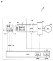
図1は、本実施の形態に係る二次電池システムが搭載された車両の全体構成を概略的に示す図である。図1を参照して、車両9は、電気自動車であって、二次電池システム1を備える。二次電池システム1は、組電池10と、監視ユニット20と、均等化ユニット30と、電子制御装置(ECU:Electronic Control Unit)100とを備える。二次電池システム1は、システムメインリレー(SMR:System Main Relay)40と、パワーコントロールユニット(PCU:Power Control Unit)50と、モータジェネレータ60とをさらに備える。
Embodiment
<Overall Configuration of Vehicle>
FIG. 1 is a view schematically showing an overall configuration of a vehicle equipped with the secondary battery system according to the present embodiment. Referring to FIG. 1, a
組電池10は、互いに並列接続された複数のブロック11〜1N(図2参照)を含む。各ブロックは、直列接続された複数(M個)のセルを含む。本実施の形態において、各セルは、リチウムイオン二次電池である。しかし、二次電池の種類は特に限定されず、各セルは、ニッケル水素電池などの他の二次電池であってもよい。
The
組電池10は、モータジェネレータ60を駆動するための電力を蓄え、PCU50を通じてモータジェネレータ60へ電力を供給する。また、組電池10は、モータジェネレータ60の発電時にPCU50を通じて発電電力を受けて充電される。
The
監視ユニット20は、電圧センサ21(後述する電圧センサ2111〜211M)と、電流センサ22と、温度センサ23とを含む。電圧センサ21は、組電池10に含まれる各セルの電圧を検出する。電流センサ22は、組電池10に入出力される電流IBを検出する。温度センサ23は、組電池10の温度を検出する。各センサは、その検出結果をECU100に出力する。
The
均等化ユニット(均等化装置)30は、組電池10に含まれる各セル間のSOCの不均等(アンバランス)を解消するために設けられる。より詳細には、組電池10では、時間の経過に伴い、セル間の自己放電電流のバラつき、または、電圧センサ21の消費電流のバラつき等に起因してセル間のSOCがバラつき得る。均等化ユニット30は、ECU100の制御信号に従って、SOC不均等を解消するために、ブロック内にて直列接続された複数のセルのうちの該当のセル(1以上のセル)を放電させる。組電池10、監視ユニット20および均等化ユニット30の詳細な構成については図2にて説明する。なお、SOCとOCV(Open Circuit Voltage)との間には、SOCの増加とともにOCVも単調増加するという相関関係が存在するので、均等化の対象はOCVであってもよい。
An equalization unit (equalization device) 30 is provided to eliminate the imbalance (unbalance) of the SOC among the cells included in the
SMR40は、PCU40と組電池10とを結ぶ電力線に電気的に接続されている。SMR40は、ECU100からの制御信号に応じて、PCU40と組電池10との間での電力の供給と遮断とを切り替える。
The SMR 40 is electrically connected to a power line connecting the PCU 40 and the assembled
PCU50は、ECU100によって制御され、組電池10とモータジェネレータ60との間で電力変換を行なう。PCU50は、組電池10から電力を受けてモータジェネレータ60を駆動するインバータと、インバータに供給される直流電圧のレベルを調整するコンバータ(いずれも図示せず)等とを含んで構成される。
PCU 50 is controlled by ECU 100 to perform power conversion between
モータジェネレータ60は、交流電動機であり、たとえば、永久磁石が埋設されたロータを備える永久磁石型同期電動機である。モータジェネレータ60は、PCU50に含まれるインバータによって駆動され、駆動軸(図示せず)を駆動する。また、モータジェネレータ60は、車両の制動時には駆動輪の回転力を受けて発電する。モータジェネレータ60によって発電された電力は、PCU50を通じて組電池10に蓄えられる。
ECU100は、CPU(Central Processing Unit)100Aと、メモリ(より具体的にはROM(Read Only Memory)およびRAM(Random Access Memory))100Bと、各種信号を入出力するための入出力ポート(図示せず)とを含んで構成されている。ECU100は、監視ユニット20の各センサから受ける信号ならびにメモリ100Bに記憶されたプログラムおよびマップ(後述する各マップ)に基づいて、組電池10を制御する。ECU100により実行される主要な制御としては、組電池10の「均等化処理」とが挙げられる。これらの処理の詳細については後述する。
The
<二次電池システムの構成>
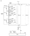
図2は、二次電池システム1の構成をより詳細に説明するための図である。図2を参照して、組電池10においては、複数(N個)のブロック(あるいはモジュールとも称される)が並列に接続されている。各ブロックにおいては、複数(M個)のセルが直列に接続されている。M,Nは、2以上の自然数である。ただし、本開示において組電池が並列接続されたブロックを含むことは必須ではなく、N=1であってもよい。N個のブロックの構成は共通であるため、以下ではブロック11の構成について代表的に説明する。
<Configuration of Secondary Battery System>
FIG. 2 is a diagram for explaining the configuration of the
ブロック11は、セル111〜11Mを含む。ブロック11には、M個の電圧センサ2111〜211Mと、M個の均等化回路311〜31Mとが設けられている。電圧センサ2111は、セル111の電圧を検出し、その検出結果をECU100に出力する。他の電圧センサ2112〜211Mも同様に、対応するセルの電圧を検出し、その検出結果をECU100に出力する。
The
なお、電流センサ22は、組電池10全体に対して1つ設けられており、組電池10全体を流れる電流IB(各ブロック11〜1Nを流れる電流の和)を検出する。ただし、ブロック11〜1N毎に電流センサが設けられてもよい。
One
均等化回路311は、セル111に並列に接続され、一般的な均等化回路と同様に、バイパス抵抗R11と、スイッチング素子(トランジスタ等)Q11とを含む。他の均等化回路312〜31Mについても同様である。
The
ECU100は、電圧センサ2111〜211Mからセル111〜11Mの電圧VB11〜VB1Mをそれぞれ取得する。さらに、ECU100は、セルの電圧からOCVを算出する。そして、ECU100は、セル111〜11M間でOCVを比較し、すべてのセル111〜11MのSOCが目的SOCに近付くように該当のセルが放電されるように、均等化回路311〜31Mを制御する。この制御を「均等化処理」と称する。図2では、均等化処理の制御信号をS11〜S1Mで示す。均等化処理を実行することで、セル111〜11M間のSOC不均等を解消することができる。
The
<満充電容量のバラつきの影響>
以上のように構成された二次電池システム1では、上述のように、均等化処理を実行するか否かの判定にセル間のOCV差が用いられる。より詳細には、セル111〜11M間のOCV差が所定のしきい値TH以上のセルが存在する場合、均等化処理が実行される。その一方で、セル111〜11M間のOCV差がしきい値TH以上のセルが存在しない場合、言い換えると、すべてのセル111〜11M間のOCV差がしきい値TH未満の場合には均等化処理は実行されない。
<Influence of variation with full charge capacity>
In the
均等化処理の実行/非実行の判定にこのような判定基準が用いられる場合に、本発明者は、セル間の満充電容量に生じた差(いわゆる満充電容量のバラつき)に起因して、均等化処理後の充放電後にセル間にOCV差が生じ得る点に着目した。 When such a criterion is used to determine whether the equalization process is performed or not, the inventor has found that the difference between the full charge capacity among the cells (so-called variation in full charge capacity) is It paid attention to the point that OCV difference may occur between cells after charge and discharge after equalization processing.
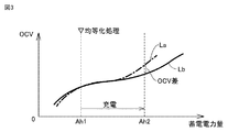
図3は、セル間の満充電容量のバラつきが均等化処理の判定に与える影響を説明するための図である。図3では、横軸に、あるセル(セル111〜11Mのいずれかのセル)に蓄えられた電力量(単位:Ah)を示し、縦軸に、そのセルのOCVを示している。あるセルAのOCVと電力量との対応関係を曲線Laで示す。また、別のセルBのOCVと電力量との対応関係を曲線Lbで示す。
FIG. 3 is a diagram for explaining the influence of variations in full charge capacity among cells on the determination of equalization processing. In FIG. 3, the horizontal axis indicates the amount of power (unit: Ah) stored in a certain cell (one of the
図3を参照して、低SOC領域において均等化処理が実行された結果、セルAに蓄えられた電力量とセルBに蓄えられた電力量とが、いずれもAh1でほぼ等しくなった状況を例に説明する。 Referring to FIG. 3, as a result of the equalization processing being performed in the low SOC region, a state in which the amount of power stored in cell A and the amount of power stored in cell B are both substantially equal at Ah1 An example will be described.
均等化処理の実行後に、組電池10を充電すると、ブロック11内のすべてのセル111〜11Mが直列に接続されているので、すべてのセル111〜11Mにほぼ等しい電力が充電される。ここでは、セルAとセルBとでは劣化の進行度合いが異なり、セルAの方がセルBよりも劣化しているとする。そのため、セルAの満充電容量がセルBの満充電容量よりも小さくなっている。そうすると、セルAに蓄えられた電力量とセルBに蓄えられた電力量とが、いずれもAh2に達した場合に、セルAのSOCとセルBのSOCとが異なることになる。一例として、セルAのSOCが85%となるのに対し、セルBのSOCが80%となる。セルのOCVとSOCとの間には対応関係(単調増加の関係)が存在するので、セルAのOCVの方がセルBのOCVよりも高くなり、OCV差が生じることとなる。このOCV差がしきい値THよりも大きい場合には、充電後の組電池10に対して均等化処理が再び実行される。このようにして、実際には不要な均等化処理が実行され、均等化処理の頻度が過度に高くなってしまう可能性がある。
When the
そこで、本実施の形態においては、OCVに基づく均等化処理の実行/非実行の判定に先立ち、OCV補正処理を実行する構成を採用する。以下に詳細に説明するように、OCV補正処理により、セル間の満充電容量のバラつきの影響を補正することができる。 Therefore, in the present embodiment, a configuration is adopted in which OCV correction processing is performed prior to the determination of execution / non-execution of equalization processing based on OCV. As described in detail below, the OCV correction process can correct the influence of variations in full charge capacity among cells.
<均等化処理フロー>
図4は、本実施の形態における均等化処理を説明するためのフローチャートである。このフローチャートは、所定条件が成立した場合または所定の演算周期が経過する毎にメインルーチンから呼び出されて実行される。また、このフローチャートの各ステップ(以下、Sと略す)は、基本的にはECU100によるソフトウェア処理によって実現されるが、ECU100内に作製された電子回路によるハードウェア処理によって実現されてもよい。
<Equilibrium processing flow>
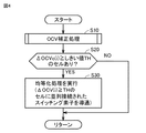
FIG. 4 is a flowchart for explaining the equalization process in the present embodiment. This flowchart is called from the main routine and executed when a predetermined condition is satisfied or whenever a predetermined operation cycle elapses. Although each step (hereinafter abbreviated as S) of this flowchart is basically realized by software processing by
図2および図4を参照して、S10において、ECU100は、ブロック11内の各セル111〜11Mに対して「OCV補正処理」を実行する。この処理については図5および図6にて詳細に説明する。
Referring to FIGS. 2 and 4, in S <b> 10,
S20において、補正後のOCV(後述するΔOCVc(i))がしきい値TH以上であるセルが存在する場合(S20においてYES)、ECU100は、処理をS30に進め、均等化処理を実行する。より詳細には、ΔOCVc(i)がしきい値TH以上であるセルに並列に接続された均等化回路について、その均等化回路内のスイッチング素子を導通させる。
In S20, when there is a cell in which the corrected OCV (ΔOCVc (i) described later) is equal to or larger than the threshold TH (YES in S20), the
一方、ΔOCVc(i)がしきい値TH以上であるセルが存在しない場合、すなわち、すべてのセルについて、ΔOCVc(i)がしきい値TH未満となる場合(S20においてNO)、ECU100は、均等化処理を実行せず、処理をメインルーチンへと戻す。
On the other hand, when there is no cell in which ΔOCVc (i) is equal to or greater than threshold TH, that is, when ΔOCVc (i) is smaller than threshold TH for all cells (NO in S20),
図5は、図4に示したOCV補正処理(S10の処理)をより詳細に説明するためのフローチャートである。図2および図5を参照して、S101において、ECU100は、すべてのセル111〜11Mの満充電容量を算出する。満充電容量の算出手法は公知であるため、詳細な説明は繰り返さない。以下、i番目のセル(iは1からMの自然数)の満充電容量をC(i)と記載する。
FIG. 5 is a flowchart for explaining the OCV correction process (the process of S10) shown in FIG. 4 in more detail. With reference to FIGS. 2 and 5, in S101,
本実施の形態におけるOCV補正処理では、ブロック11内のセル111〜11Mのうちのいずかのセルが基準として選択される。どのセルを選択することも可能であるため、以下では説明の簡略化のため、セル111を基準として選択した場合を例に説明する。S102において、ECU100は、セル111の満充電容量C(1)を「基準容量」であるCREFとして設定する。また、ECU100は、セル111のSOCを推定し、その推定されたSOCを「基準SOC」であるSREFとして設定する。
In the OCV correction process in the present embodiment, any one of the
S103において、ECU100は、仮に均等化処理を実行した場合に、すべてのセルの目標とするSOC(均等化処理によりSOCを近付ける目標値)である「目標SOC」STAGを設定する。なお、目標SOC(STAG)としては、できるだけ長いEV走行可能距離(組電池10に蓄えられた電力で車両9が走行可能な距離)を確保するため、すべてのセル111〜11MのSOCのうち最も低いSOC以下であるものの、ある程度、高いSOCを設定することが好ましい。
In S103, the
以降のS104〜S107の処理は、基準セル(セル111)以外の対象セル(セル112〜11M)の各々について実行される。ここではセル112について、S104〜S107の一連の処理が実行される場合を例に説明する。最初の対象となるセル112に対する処理の実行後には、残りのセル113〜11Mに対しても同様に一連の処理が実行される。
The subsequent processes of S104 to S107 are executed for each of the target cells (
S104において、ECU100は、セル112について、基準セル(セル111)との間でOCVを比較するために用いられる「比較SOC」として、SCMP(2)を算出する。より詳細には、SCMP(2)は、以下のように算出される。
In S104, the
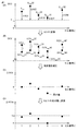
図6は、OCV補正処理におけるS104〜S109の処理を説明するための図である。図6において、横軸は、ブロック11内のセル番号i(i=1〜M)を示す。縦軸は、上から順に、セルのSOC、セルのOCV、S109の処理の実行前のΔOCV(S107にて算出されたΔOCV)、および、S109の処理の実行後のΔOCVcを示す。
FIG. 6 is a diagram for explaining the processing of S104 to S109 in the OCV correction processing. In FIG. 6, the horizontal axis indicates cell numbers i (i = 1 to M) in the
図6(A)を参照して、ここでは、基準セルを用いた比較を行なうため、各々のSOCが目標SOC(STAG)に達するまで、基準セルであるセル111と、対象セルであるセル112とが放電される状況を想定する。
Referring to FIG. 6A, here, in order to perform comparison using a reference cell,
セル112からの放電電力量と、セル111からの放電電力量とが等しいと仮定する。このように放電電力量が等しい場合、放電に伴うSOC変化量が相対的に大きいことは、満充電容量が相対的に小さいことを意味する。そのため、SOCが目標SOCに達するまで放電される際のセル112のSOC変化量ΔS(2)と、SOCが目標SOCに達するまで放電される際のセル111のSOC変化量ΔS(1)との比(ΔS(2):ΔS(1))は、セル112の満充電容量C(2)の逆数と、セル111の満充電容量の逆数との比に等しくなる。一例として、ΔS(2)=4%であり、ΔS(1)=5%である場合、セル112の方がセル111と比べて満充電容量が大きく、セル112の満充電容量C(2)とセル111の満充電容量との比は5:4になる。
It is assumed that the amount of discharge power from the
このことは、より一般的に、下記式(1)のように表される。つまり、比較SOCであるSCMP(2)と目標SOCであるSTAGとの差(SCMP(2)−STAG)と、基準SOCであるSREFと目標SOCであるSTAGとの差(SREF−STAG)との比は、1/C(2)と1/CREFとの比に等しい。
(SCMP(2)−STAG):(SREF−STAG)=1/C(2):1/CREF
・・・(1)
This is more generally expressed as the following formula (1). That is, the difference (S CMP (2)-S TAG ) between the comparison SOC S CMP (2) and the target SOC STAG, and the difference between the reference SOC S REF and the target SOC S TAG (S The ratio to REF -S TAG ) is equal to the ratio of 1 / C (2) to 1 / C REF .
(S CMP (2)-S TAG ): (S REF- S TAG ) = 1 / C (2): 1 / C REF
... (1)
式(1)を変形すると、下記式(2)が得られる。式(2)にS101〜S103にて算出された各パラメータを代入することで、比較SOC(SCMP(2))が算出される。
SCMP(2)=STAG−(STAG−SREF)×C(2)/CREF
・・・(2)
The following equation (2) is obtained by modifying the equation (1). The comparison SOC (S CMP (2)) is calculated by substituting the parameters calculated in S101 to S103 into the equation (2).
S CMP (2) = S TAG − (S TAG −S REF ) × C (2) / C REF
... (2)
セル112の比較SOC(SCMP(2))とは、基準SOC(SREF)を基準とした上で、基準容量CREFに対するセル112の満充電容量のバラつきの影響を考慮して、セル112のSOCを算出した値である。式(2)より、セル112の満充電容量C(2)以外では、目標SOC(STAG)と、基準となるセル111に関するパラメータ(SREFおよびCREF)とのみを用いてSCMP(2)が表されていることが分かる。そのため、セル112〜11M間で比較SOC同士を比較することで、基準容量CREFに対するセル112〜11Mの満充電容量のバラつきの影響によるSOCずれを比較することができる。
The comparison SOC (S CMP (2)) of the
図5および図6(B)を参照して、S105において、ECU100は、メモリ100Bに予め格納されたSOC−OCVカーブを示すマップ(図示せず)を参照することにより、S104にて算出された比較SOC(SCMP(2))に対応するOCVである「比較OCV」として、OCVCMP(2)を算出する。なお、基準となるセル111についても同様に、SOCREFからOCVREFが算出される。
5 and 6B, in S105,
さらに、ECU100は、電圧センサ2112および電流センサ22を用いて、セル112のOCVを測定する(S106)。このように測定されたセル112のOCVを「測定OCV」と称し、OCVMSR(2)と記載する。なお、測定OCVは、たとえば、組電池10の充放電されていない状態が継続し、分極が解消された後の電圧測定値から求めることができる。
Furthermore, the
図5および図6(C)を参照して、S107において、ECU100は、S105にて算出された比較OCV(OCVCMP(2))と、S106にて測定された測定OCV(OCVMSR(2))との差分を下記式(3)に従って算出する。
ΔOCV(2)=OCVCMP(2)−OCVMSR(2) ・・・(3)
Referring to FIGS. 5 and 6C, in S107,
ΔOCV (2) = OCV CMP (2)-OCV MSR (2) (3)
この差分は、満充電容量のバラつきの影響を考慮したOCV(比較OCV)と、実測されたOCV(測定OCV)との差分であり、OCVの実測値を、満充電容量のバラつきの影響を考慮した理想値により補正したものと理解される。このズレを「OCVずれ」と称し、i番目のセルのOCVずれを「ΔOCV(i)」と記載する。 This difference is the difference between the OCV (comparison OCV) in consideration of the effect of the variation in the full charge capacity and the measured OCV (measured OCV), and the actual value of the OCV is considered in the effect of the variation in the full charge capacity It is understood that it is corrected by the ideal value. This shift is referred to as "OCV shift", and the OCV shift of the i-th cell is described as "ΔOCV (i)".
なお、S104〜S107の処理は、本開示に係る「第1の処理」〜「第4の処理」にそれぞれ相当する。 In addition, the process of S104-S107 is respectively corresponded to the "1st process"-"4th process" concerning this indication.
S108において、ECU100は、基準として選択したセル以外のすべてのセル(この例では、セル111以外の全セル112〜11M)について、OCVずれΔOCV(i)(i=2〜M)の算出が完了したか否かを判定する。すべてのセルに対してOCVずれΔOCV(i)の算出が完了していない場合(S108においてNO)には処理がS104に戻され、次のセルに対してS104〜S107の処理が再び実行される。
In S108, the
すべてのセルに対してOCVずれΔOCV(i)の算出が完了すると(S108においてYES)、ECU100は、処理をS109に進め、S107にて算出されたOCVずれΔOCVの換算処理を実行する。より具体的には、下記式(4)に示すように、各セル111〜11Mについて、そのセルのOCVずれΔOCV(i)と、全セルのOCVずれの最小値との差が算出される。この差を「ΔOCVc(i)」と記載する。
ΔOCVc(i)=ΔOCV(i)−min(ΔOCV(i)) ・・・(4)
When the calculation of the OCV deviation ΔOCV (i) is completed for all cells (YES in S108), the
ΔOCVc (i) = ΔOCV (i) −min (ΔOCV (i)) (4)
図6(C)に示すように、S109の処理の実行前のΔOCVΔ(i)は、基準としたセル111では0であるが、他のセル112〜11Mでは正負様々な値を取り得る。
As shown in FIG. 6C, .DELTA.OCV.DELTA. (I) before execution of the process of S109 is 0 in the
そこで、各セルのΔOCV(i)から、ΔOCV(i)の最小値(図6(C)に示す例では、5番目のセルのΔOCV(5))を差し引くことで、図6(D)に示すように、すべてのセルのΔOCVc(i)が0以上(0または正値)となる。これにより、図4のS20の処理にてΔOCVc(i)としきい値THとが比較されるところ、しきい値THとして正値を設定することができるとともに、負値のΔOCVc(i)については考慮しなくてよくなり、比較演算が単純化される。ただし、S109の処理は必須ではなく、各セルのΔOCV(i)の別のしきい値(正値に限らない)と比較してもよい。 Therefore, the ΔOCV (i) of each cell is subtracted the ΔOCV (5) of the fifth cell in the example shown in FIG. 6 (C) from the minimum value of ΔOCV (i), as shown in FIG. 6 (D). As shown, ΔOCVc (i) of all cells is 0 or more (0 or a positive value). Thus, while ΔOCVc (i) and the threshold value TH are compared in the process of S20 of FIG. 4, a positive value can be set as the threshold value TH, and the negative value ΔOCVc (i) can be set. There is no need to consider, and the comparison operation is simplified. However, the process of S109 is not essential, and may be compared with another threshold value (not limited to a positive value) of ΔOCV (i) of each cell.
以上のように、本実施の形態によれば、OCV補正処理のS104〜S107の処理により、基準セルであるセル111の満充電容量(基準容量CREF)を基準とした場合の、セル間の満充電容量のバラつきの影響を補正することができる。これにより、均等化処理の実行後に再度均等化処理が実行されることが防止されるので、均等化処理の頻度の過度の上昇を抑制することができる。
As described above, according to the present embodiment, the processing between S104 and S107 of the OCV correction processing makes it possible to obtain an inter-cell relationship based on the full charge capacity (reference capacitance C REF ) of the
今回開示された実施の形態は、すべての点で例示であって制限的なものではないと考えられるべきである。本開示の範囲は、上記した実施の形態の説明ではなくて特許請求の範囲によって示され、特許請求の範囲と均等の意味および範囲内でのすべての変更が含まれることが意図される。 It should be understood that the embodiments disclosed herein are illustrative and non-restrictive in every respect. The scope of the present disclosure is indicated not by the description of the embodiments described above but by the claims, and is intended to include all modifications within the meaning and scope equivalent to the claims.
1 二次電池システム、10 組電池、11〜11N ブロック、111〜11M セル、20 監視ユニット、21,2111〜211M 電圧センサ、22 電流センサ、23 温度センサ、30 均等化ユニット、40 SMR、50 PCU、60 モータジェネレータ、311〜31M 均等化回路、R11〜R1M バイパス抵抗、Q11〜Q1M スイッチング素子、100 ECU、100A CPU、100B メモリ、9 車両。
Claims (1)
前記複数のセルにそれぞれ並列接続された複数のスイッチング素子のうちの少なくとも1つのスイッチング素子を導通させることにより、前記複数のセルのSOCが目標SOCに近付くように前記複数のセルのSOCを均等化する均等化処理を実行可能に構成された均等化装置と、
前記均等化装置を制御する制御装置とを備え、
前記制御装置は、前記複数のセルのうちのいずれかの基準セルのSOCを推定するとともに、前記基準セル以外の対象セルの各々について第1〜第4の処理を実行し、
前記第1の処理は、前記目標SOC、前記基準セルのSOC、前記基準セルの満充電容量および前記対象セルの満充電容量の間に成立する関係を用いて、前記対象セルのSOCを算出する処理であり、
前記第2の処理は、所定のSOCとOCVとの対応関係を参照することによって、前記第1の処理により算出されたSOCに対応するOCVを算出する処理であり、
前記第3の処理は、前記対象セルのOCVを測定する処理であり、
前記第4の処理は、前記第2の処理によるOCVの算出値と前記第3の処理によるOCVの測定値との差分を算出することで、前記基準セルの満充電容量に対する前記対象セルの満充電容量のずれの影響を前記第3の処理によるOCVの測定値に反映させる補正を行なう処理であり、
前記制御装置は、前記第4の処理による補正後のOCVの測定値が所定のしきい値を上回るセルが存在しない場合には前記均等化処理を実行しない、二次電池システム。 An assembled battery including a plurality of cells connected in series;
By conducting at least one of the plurality of switching elements connected in parallel to the plurality of cells, the SOCs of the plurality of cells are equalized so that the SOCs of the plurality of cells approach the target SOC. An equalization device configured to be able to execute an equalization process
A control device for controlling the equalization device;
The control device estimates the SOC of any one of the plurality of cells, and executes the first to fourth processes for each of the target cells other than the reference cell.
The first process calculates the SOC of the target cell using a relationship established between the target SOC, the SOC of the reference cell, the full charge capacity of the reference cell, and the full charge capacity of the target cell. Processing,
The second process is a process of calculating an OCV corresponding to the SOC calculated by the first process by referring to a correspondence between a predetermined SOC and an OCV.
The third process is a process of measuring the OCV of the target cell,
In the fourth process, the difference between the calculated value of OCV by the second process and the measured value of OCV by the third process is calculated to obtain the fullness of the target cell with respect to the full charge capacity of the reference cell. A process of performing correction to reflect the influence of the deviation of the charge capacity on the measured value of OCV by the third process,
The said control apparatus is a secondary battery system which does not perform the said equalization process, when the measured value of OCV after correction | amendment by the said 4th process does not exceed a predetermined | prescribed threshold value.
Priority Applications (1)
| Application Number | Priority Date | Filing Date | Title |
|---|---|---|---|
| JP2017198323A JP6897479B2 (en) | 2017-10-12 | 2017-10-12 | Rechargeable battery system |
Applications Claiming Priority (1)
| Application Number | Priority Date | Filing Date | Title |
|---|---|---|---|
| JP2017198323A JP6897479B2 (en) | 2017-10-12 | 2017-10-12 | Rechargeable battery system |
Publications (2)
| Publication Number | Publication Date |
|---|---|
| JP2019075845A true JP2019075845A (en) | 2019-05-16 |
| JP6897479B2 JP6897479B2 (en) | 2021-06-30 |
Family
ID=66544388
Family Applications (1)
| Application Number | Title | Priority Date | Filing Date |
|---|---|---|---|
| JP2017198323A Expired - Fee Related JP6897479B2 (en) | 2017-10-12 | 2017-10-12 | Rechargeable battery system |
Country Status (1)
| Country | Link |
|---|---|
| JP (1) | JP6897479B2 (en) |
Cited By (1)
| Publication number | Priority date | Publication date | Assignee | Title |
|---|---|---|---|---|
| CN111048857A (en) * | 2019-12-20 | 2020-04-21 | 宁德时代新能源科技股份有限公司 | OCV-SOC curve updating method of battery pack, battery management system and vehicle |
Families Citing this family (1)
| Publication number | Priority date | Publication date | Assignee | Title |
|---|---|---|---|---|
| KR102758018B1 (en) | 2021-02-16 | 2025-01-21 | 주식회사 엘지에너지솔루션 | Battery management system, battery pack, energy storage system, and battery management method |
Citations (4)
| Publication number | Priority date | Publication date | Assignee | Title |
|---|---|---|---|---|
| JPH10322925A (en) * | 1997-05-12 | 1998-12-04 | Nissan Motor Co Ltd | Battery charging rate adjustment device for assembled batteries |
| JP2004031012A (en) * | 2002-06-24 | 2004-01-29 | Nissan Motor Co Ltd | Battery capacity adjustment apparatus and method |
| JP2013027110A (en) * | 2011-07-19 | 2013-02-04 | Hitachi Ltd | Cell system |
| JP2014102076A (en) * | 2012-11-16 | 2014-06-05 | Denso Corp | Battery system |
-
2017
- 2017-10-12 JP JP2017198323A patent/JP6897479B2/en not_active Expired - Fee Related
Patent Citations (4)
| Publication number | Priority date | Publication date | Assignee | Title |
|---|---|---|---|---|
| JPH10322925A (en) * | 1997-05-12 | 1998-12-04 | Nissan Motor Co Ltd | Battery charging rate adjustment device for assembled batteries |
| JP2004031012A (en) * | 2002-06-24 | 2004-01-29 | Nissan Motor Co Ltd | Battery capacity adjustment apparatus and method |
| JP2013027110A (en) * | 2011-07-19 | 2013-02-04 | Hitachi Ltd | Cell system |
| JP2014102076A (en) * | 2012-11-16 | 2014-06-05 | Denso Corp | Battery system |
Cited By (2)
| Publication number | Priority date | Publication date | Assignee | Title |
|---|---|---|---|---|
| CN111048857A (en) * | 2019-12-20 | 2020-04-21 | 宁德时代新能源科技股份有限公司 | OCV-SOC curve updating method of battery pack, battery management system and vehicle |
| CN111048857B (en) * | 2019-12-20 | 2022-01-11 | 宁德时代新能源科技股份有限公司 | OCV-SOC curve updating method of battery pack, battery management system and vehicle |
Also Published As
| Publication number | Publication date |
|---|---|
| JP6897479B2 (en) | 2021-06-30 |
Similar Documents
| Publication | Publication Date | Title |
|---|---|---|
| US10048322B2 (en) | Method of measuring battery pack current and correcting offsets of a current sensor | |
| CN107533109B (en) | Battery control device and electric vehicle system | |
| JP5086076B2 (en) | Method for cell balancing for lithium battery systems | |
| CN102975630B (en) | For motor vehicle supply unit and the vehicle possessing this supply unit | |
| US9438059B2 (en) | Battery control apparatus and battery control method | |
| US8497661B2 (en) | Equalization device, equalization processing program, battery system, electric vehicle and equalization processing method | |
| CN102445665B (en) | Battery pack capacity learning algorithm | |
| JP4157317B2 (en) | Status detection device and various devices using the same | |
| CN106662620B (en) | Battery state detection device, secondary battery system, storage medium, and battery state detection method | |
| CN103545862B (en) | Battery management unit for vehicle | |
| JP6572448B2 (en) | Battery state estimation device and power supply device | |
| CN104364116B (en) | Accumulating system and equalization methods | |
| CN107852002B (en) | Method and system for balancing battery packs | |
| WO2018056263A1 (en) | Power supply system | |
| US20180118049A1 (en) | Apparatus and method for controlling charging of battery for hybrid vehicle | |
| JP6174963B2 (en) | Battery control system | |
| JP6011265B2 (en) | Battery system | |
| CN103460062A (en) | Device for measuring degradation, rechargeable battery pack, method for measuring degradation, and program | |
| JP6711221B2 (en) | Battery system | |
| US20120109617A1 (en) | Optimization of electrical component parameters in energy storage system models | |
| JP6897479B2 (en) | Rechargeable battery system | |
| JP6885840B2 (en) | Battery control system | |
| JP4930434B2 (en) | Secondary battery module controller | |
| JP6760133B2 (en) | Battery system | |
| JP7040408B2 (en) | Rechargeable battery system |
Legal Events
| Date | Code | Title | Description |
|---|---|---|---|
| A621 | Written request for application examination |
Free format text: JAPANESE INTERMEDIATE CODE: A621 Effective date: 20200213 |
|
| TRDD | Decision of grant or rejection written | ||
| A01 | Written decision to grant a patent or to grant a registration (utility model) |
Free format text: JAPANESE INTERMEDIATE CODE: A01 Effective date: 20210511 |
|
| A61 | First payment of annual fees (during grant procedure) |
Free format text: JAPANESE INTERMEDIATE CODE: A61 Effective date: 20210524 |
|
| R151 | Written notification of patent or utility model registration |
Ref document number: 6897479 Country of ref document: JP Free format text: JAPANESE INTERMEDIATE CODE: R151 |
|
| LAPS | Cancellation because of no payment of annual fees |