JP2019078331A - Eddy current-type damper - Google Patents
Eddy current-type damper Download PDFInfo
- Publication number
- JP2019078331A JP2019078331A JP2017205621A JP2017205621A JP2019078331A JP 2019078331 A JP2019078331 A JP 2019078331A JP 2017205621 A JP2017205621 A JP 2017205621A JP 2017205621 A JP2017205621 A JP 2017205621A JP 2019078331 A JP2019078331 A JP 2019078331A
- Authority
- JP
- Japan
- Prior art keywords
- ball nut
- holding member
- conductive member
- eddy current
- permanent magnet
- Prior art date
- Legal status (The legal status is an assumption and is not a legal conclusion. Google has not performed a legal analysis and makes no representation as to the accuracy of the status listed.)
- Pending
Links
Images





Landscapes
- Buildings Adapted To Withstand Abnormal External Influences (AREA)
- Vibration Prevention Devices (AREA)
Abstract
【課題】ボールナットの温度上昇に起因する振動減衰性能の低下及び耐久性の低下を抑制できる渦電流式ダンパを提供する。【解決手段】渦電流式ダンパ1は、ねじ軸7と、複数の第1永久磁石3と、複数の第2永久磁石4と、円筒形状の磁石保持部材2と、導電性を有する円筒形状の導電部材5と、ねじ軸7と噛み合うボールナット6と、断熱部材12と、を備える。第1永久磁石3は、ねじ軸7の周りに円周方向に沿って配列される。第2永久磁石4は、第1永久磁石3同士の間に配置され、第1永久磁石3と磁極の配置が反転する。磁石保持部材2は、第1永久磁石3及び第2永久磁石4を保持する。導電部材5は、第1永久磁石3及び第2永久磁石4と隙間を空けて対向する。ボールナット6は、磁石保持部材2に固定される。断熱部材12は、ボールナット6と磁石保持部材2との取付部分に設けられる。【選択図】図2PROBLEM TO BE SOLVED: To provide an eddy current type damper capable of suppressing a decrease in vibration damping performance and a decrease in durability due to a temperature rise of a ball nut. An eddy current type damper 1 has a screw shaft 7, a plurality of first permanent magnets 3, a plurality of second permanent magnets 4, a cylindrical magnet holding member 2, and a cylindrical shape having conductivity. A conductive member 5, a ball nut 6 that meshes with a screw shaft 7, and a heat insulating member 12 are provided. The first permanent magnets 3 are arranged around the screw shaft 7 along the circumferential direction. The second permanent magnet 4 is arranged between the first permanent magnets 3, and the arrangement of the first permanent magnet 3 and the magnetic pole is reversed. The magnet holding member 2 holds the first permanent magnet 3 and the second permanent magnet 4. The conductive member 5 faces the first permanent magnet 3 and the second permanent magnet 4 with a gap. The ball nut 6 is fixed to the magnet holding member 2. The heat insulating member 12 is provided at a mounting portion between the ball nut 6 and the magnet holding member 2. [Selection diagram] Fig. 2
Description
本発明は、渦電流式ダンパに関する。 The present invention relates to an eddy current damper.
地震等による振動から建築物を保護するために、建築物に制震装置が取り付けられる。制震装置は建築物に与えられた運動エネルギを他のエネルギ(例:熱エネルギ)に変換する。これにより、建築物の大きな揺れが抑制される。制震装置はたとえば、ダンパである。ダンパの種類はたとえば、オイル式、せん断抵抗式がある。一般に、建築物にはオイル式やせん断抵抗式ダンパが使用されることが多い。オイル式ダンパは、シリンダ内の非圧縮性流体を利用して振動を減衰させる。せん断抵抗式ダンパは、粘性流体のせん断抵抗を利用して振動を減衰させる。 In order to protect the building from vibrations due to earthquakes, etc., a damping system is attached to the building. The vibration control device converts kinetic energy given to the building into other energy (eg, thermal energy). This suppresses large shaking of the building. The vibration control device is, for example, a damper. The types of dampers are, for example, oil type and shear resistance type. In general, oil type and shear resistance type dampers are often used in buildings. The oil type damper uses the incompressible fluid in the cylinder to damp the vibration. The shear resistance damper damps the vibration by using the shear resistance of the viscous fluid.
しかしながら、特にせん断抵抗式ダンパで用いられる粘性流体の粘度は、粘性流体の温度に依存する。すなわち、せん断抵抗式ダンパの減衰力は、温度に依存する。したがって、せん断抵抗式ダンパを建築物に使用する際には、使用環境を考慮して適切な粘性流体を選択する必要がある。また、オイル式やせん断抵抗式などの流体を用いているダンパは、温度上昇等によって流体の圧力が上昇し、シリンダのシール材などの機械的な要素が破損する恐れがある。減衰力が温度に依存しないダンパとして、渦電流式ダンパがある。 However, the viscosity of the viscous fluid used in particular in shear resistant dampers depends on the temperature of the viscous fluid. That is, the damping force of the shear resistance damper depends on the temperature. Therefore, when using a shear resistant damper in a building, it is necessary to select an appropriate viscous fluid in consideration of the use environment. Further, in a damper using a fluid such as an oil type or a shear resistance type, the pressure of the fluid may rise due to temperature rise and the like, and mechanical elements such as the seal material of the cylinder may be damaged. As a damper whose damping force does not depend on temperature, there is an eddy current damper.
従来の渦電流式ダンパはたとえば、特公平5−86496号公報(特許文献1)に開示される。 A conventional eddy current type damper is disclosed, for example, in Japanese Patent Publication No. 5-86496 (Patent Document 1).
特許文献1の渦電流式ダンパは、主筒に取り付けられた複数の永久磁石と、ねじ軸に接続されたヒステリシス材と、ねじ軸と噛み合うボールナットと、ボールナットに接続された副筒と、を備える。複数の永久磁石は、磁極の配置が交互に異なる。ヒステリシス材は導電性を有する。以下では、ヒステリシス材を導電部材ともいう。主筒を磁石保持部材ともいう。ヒステリシス材は、複数の永久磁石と対向し、相対回転可能である。この渦電流式ダンパに運動エネルギが与えられると、副筒及びボールナットが主筒の案内によって軸方向に移動し、ボールねじの作用によってヒステリシス材が回転する。これにより、ヒステリシス損により運動エネルギが消費される。また、ヒステリシス材に渦電流が発生するため、渦電流損により運動エネルギが消費される、と特許文献1には記載されている。
The eddy current damper of
特許文献1の渦電流式ダンパでは、複数の永久磁石が円周方向に沿って配列される。このダンパに運動エネルギが与えられると、永久磁石のそれぞれによって生じる磁界の中で導電部材(ヒステリシス材)が回転する。その際、導電部材の表面のうち、永久磁石のそれぞれと対向する領域にそれぞれ渦電流が発生する。これにより、回転する導電部材に制動力が与えられ、減衰力が発生する。さらに、渦電流が発生した領域のそれぞれが発熱する。そのため、導電部材の温度が上昇する。また、導電部材からの輻射熱によって、導電部材の発熱面に近接する磁石保持部材(主筒)の温度も次第に上昇する。
In the eddy current damper of
ここで、制震装置として用いられる渦電流式ダンパでは、振動を減衰するために、ねじ軸又はボールナットが軸方向に往復運動する。その際、ボールねじによる直線運動と回転運動との相互変換を円滑に行えることが重要である。とりわけ、往復運動の切り替わり時に、バックラッシが発生したり、偏荷重が作用したりしないようにすることが重要である。そのため、ボールナットとねじ軸との噛み合い部には、極めて高い寸法精度が要求される。 Here, in an eddy current type damper used as a vibration control device, a screw shaft or a ball nut reciprocates in the axial direction in order to damp the vibration. At that time, it is important to be able to smoothly convert the linear motion and the rotational motion by the ball screw. In particular, it is important that backlash does not occur or unbalanced load does not occur when switching between reciprocating movements. Therefore, extremely high dimensional accuracy is required for the engagement portion between the ball nut and the screw shaft.
しかしながら、特許文献1の渦電流式ダンパの場合、磁石保持部材の熱がボールナットに伝わる。ボールナットが磁石保持部材と摺動可能に接触しているからである。そのため、ボールナットの温度が上昇する。この場合、ボールナットが熱膨張する。ボールナットが熱膨張すれば、噛み合い部の寸法精度が後発的に悪化する。これにより、ボールねじによる運動変換効率が低下し、振動に対する減衰性能が低下するおそれがある。
However, in the case of the eddy current damper of
通常、ボールナットとねじ軸との噛み合い部には潤滑剤が供給されている。潤滑剤によって噛み合い部の接触抵抗を下げるためである。しかしながら、ボールナットの温度が上昇すれば、潤滑剤の温度も上昇する。この場合、潤滑剤の特性が失われ、ねじ軸がボールナットに焼き付くおそれがある。 Usually, a lubricant is supplied to the engagement portion between the ball nut and the screw shaft. The purpose of this is to reduce the contact resistance of the meshing portion by the lubricant. However, if the temperature of the ball nut rises, the temperature of the lubricant also rises. In this case, the properties of the lubricant are lost, and the screw shaft may be seized on the ball nut.
通常、ボールナットには高硬度の鋼材が使用される。噛み合い部の耐摩耗性を高めるためである。しかしながら、ボールナットの温度が過度に上昇すれば、ボールナットが軟化する。この場合、噛み合い部の耐摩耗性が低下するおそれがある。 Usually, high hardness steel is used for the ball nut. This is to increase the wear resistance of the engagement portion. However, if the temperature of the ball nut rises excessively, the ball nut softens. In this case, there is a possibility that the wear resistance of the engagement portion may be reduced.
要するに、従来の渦電流式ダンパでは、導電部材の温度上昇によるボールナットの温度上昇に起因して、振動に対する減衰性能が低下したり、耐久性が損なわれたりするおそれがある。 In short, in the conventional eddy current type damper, there is a possibility that the damping performance against vibration may be deteriorated or the durability may be deteriorated due to the temperature rise of the ball nut due to the temperature rise of the conductive member.
本発明の目的は、ボールナットの温度上昇に起因する振動減衰性能の低下及び耐久性の低下を抑制できる渦電流式ダンパを提供することである。 An object of the present invention is to provide an eddy current damper that can suppress the deterioration of vibration damping performance and the deterioration of durability due to the temperature rise of a ball nut.
本実施形態の渦電流式ダンパは、ねじ軸と、ねじ軸の周りに円周方向に沿って配列された複数の第1永久磁石と、第1永久磁石同士の間に配置され、第1永久磁石と磁極の配置が反転した複数の第2永久磁石と、第1永久磁石及び第2永久磁石を保持する円筒形状の磁石保持部材と、導電性を有し、第1永久磁石及び第2永久磁石と隙間を空けて対向する円筒形状の導電部材と、磁石保持部材又は導電部材に固定され、ねじ軸と噛み合うボールナットと、ボールナットが磁石保持部材に固定される場合、ボールナットと磁石保持部材との取付部分に設けられ、ボールナットが導電部材に固定される場合、ボールナットと導電部材との取付部分に設けられる、熱伝導抑制機構と、を備える。 The eddy current damper of the present embodiment is disposed between a screw shaft, a plurality of first permanent magnets arranged along a circumferential direction around the screw shaft, and the first permanent magnets, A plurality of second permanent magnets in which the arrangement of the magnet and the magnetic pole is reversed, a cylindrical magnet holding member holding the first permanent magnet and the second permanent magnet, and conductivity, the first permanent magnet and the second permanent When a cylindrical conductive member opposed to a magnet with a gap is provided, a ball nut fixed to a magnet holding member or a conductive member and meshed with a screw shaft, and a ball nut fixed to a magnet holding member, the ball nut and the magnet holding A heat conduction suppressing mechanism is provided at an attachment portion with the member, and when the ball nut is fixed to the conductive member, provided at the attachment portion between the ball nut and the conductive member.
本実施形態の渦電流式ダンパによれば、導電部材に渦電流が生じて導電部材の温度が上昇しても、熱伝導抑制機構によってボールナットの温度上昇が抑制される。そのため、ボールナットの温度上昇に起因する振動減衰性能の低下及び耐久性の低下を抑制できる。 According to the eddy current damper of the present embodiment, even if an eddy current is generated in the conductive member and the temperature of the conductive member rises, the temperature rise of the ball nut is suppressed by the heat conduction suppressing mechanism. Therefore, it is possible to suppress a decrease in vibration damping performance and a decrease in durability due to the temperature rise of the ball nut.
本実施形態の渦電流式ダンパは、ねじ軸と、複数の第1永久磁石と、複数の第2永久磁石と、円筒形状の磁石保持部材と、導電性を有する円筒形状の導電部材と、ねじ軸と噛み合うボールナットと、熱伝導抑制機構と、を備える。第1永久磁石は、ねじ軸の周りに円周方向に沿って配列される。第2永久磁石は、第1永久磁石同士の間に配置され、第1永久磁石と磁極の配置が反転する。磁石保持部材は、第1永久磁石及び第2永久磁石を保持する。導電部材は、第1永久磁石及び第2永久磁石と隙間を空けて対向する。ボールナットは、磁石保持部材又は導電部材に固定される。ボールナットが磁石保持部材に固定される場合、熱伝導抑制機構はボールナットと磁石保持部材との取付部分に設けられる。ボールナットが導電部材に固定される場合、熱伝導抑制機構はボールナットと導電部材との取付部分に設けられる。 The eddy current damper according to the present embodiment includes a screw shaft, a plurality of first permanent magnets, a plurality of second permanent magnets, a cylindrical magnet holding member, a cylindrical conductive member having conductivity, and a screw. A ball nut engaged with the shaft, and a heat conduction suppressing mechanism. The first permanent magnets are arranged circumferentially around the screw axis. The second permanent magnet is disposed between the first permanent magnets, and the arrangement of the first permanent magnet and the magnetic pole is reversed. The magnet holding member holds the first permanent magnet and the second permanent magnet. The conductive member opposes the first permanent magnet and the second permanent magnet with a gap. The ball nut is fixed to the magnet holding member or the conductive member. When the ball nut is fixed to the magnet holding member, the heat conduction suppressing mechanism is provided at the mounting portion of the ball nut and the magnet holding member. When the ball nut is fixed to the conductive member, the heat conduction suppressing mechanism is provided at the attachment portion between the ball nut and the conductive member.
本実施形態の渦電流式ダンパによれば、ダンパに運動エネルギが与えられると、ねじ軸が軸方向に移動する。ねじ軸の軸方向の移動により、ボールナットが回転する。これにより、第1及び第2永久磁石のそれぞれによって生じる磁界の中で、導電部材が第1及び第2の永久磁石に対して相対回転する。その際、導電部材の表面のうち、第1及び第2永久磁石のそれぞれと対向する領域にそれぞれ渦電流が発生する。これにより、回転する導電部材に制動力が与えられ、減衰力が発生する。さらに、渦電流が発生した領域のそれぞれが発熱する。そのため、導電部材の温度が上昇する。また、導電部材からの輻射熱によって、導電部材の発熱面に近接する磁石保持部材の温度も次第に上昇する。 According to the eddy current damper of the present embodiment, when kinetic energy is given to the damper, the screw shaft moves in the axial direction. The axial movement of the screw shaft causes the ball nut to rotate. Thereby, the conductive member rotates relative to the first and second permanent magnets in the magnetic field generated by each of the first and second permanent magnets. At this time, eddy currents are generated in the regions of the surface of the conductive member facing the respective first and second permanent magnets. Thereby, a damping force is applied to the rotating conductive member, and a damping force is generated. Furthermore, each of the regions where the eddy current is generated generates heat. Therefore, the temperature of the conductive member rises. In addition, the temperature of the magnet holding member adjacent to the heat generating surface of the conductive member is also gradually raised by the radiant heat from the conductive member.
ここで、ボールナットが磁石保持部材に固定される場合、ボールナットと磁石保持部材との取付部分に設けられた熱伝導抑制機構によって、磁石保持部材からボールナットへの熱伝導が抑制される。ボールナットが導電部材に固定される場合、ボールナットと導電部材との取付部分に設けられた熱伝導抑制機構によって、導電部材からボールナットへの熱伝導が抑制される。いずれの場合も、ボールナットの温度上昇が抑制される。 Here, when the ball nut is fixed to the magnet holding member, heat conduction from the magnet holding member to the ball nut is suppressed by the heat conduction suppressing mechanism provided in the mounting portion between the ball nut and the magnet holding member. When the ball nut is fixed to the conductive member, heat conduction from the conductive member to the ball nut is suppressed by the heat conduction suppressing mechanism provided in the mounting portion between the ball nut and the conductive member. In any case, the temperature rise of the ball nut is suppressed.
その場合、ボールナットの熱膨張が抑制され、ボールナットとねじ軸との噛み合い部の寸法精度が確保される。そのため、ボールねじによる運動変換効率を確保できる。また、噛み合い部に存在する潤滑剤の温度上昇が抑制される。そのため、潤滑剤の特性を確保できる。さらに、ボールナットの軟化が抑制される。したがって、ボールナットの温度上昇に起因する振動減衰性能の低下及び耐久性の低下を抑制できる。 In that case, the thermal expansion of the ball nut is suppressed, and the dimensional accuracy of the engagement portion between the ball nut and the screw shaft is secured. Therefore, the motion conversion efficiency by the ball screw can be secured. Further, the temperature rise of the lubricant present in the meshing portion is suppressed. Therefore, the characteristics of the lubricant can be secured. Furthermore, the softening of the ball nut is suppressed. Therefore, it is possible to suppress a decrease in vibration damping performance and a decrease in durability due to the temperature rise of the ball nut.
上記した本実施形態の渦電流式ダンパは、下記の(1)〜(4)のいずれかの構成を採用することができる。 The above-described eddy current damper of the present embodiment can adopt any of the following configurations (1) to (4).
(1)磁石保持部材が導電部材の内側に配置される。第1永久磁石及び第2永久磁石が磁石保持部材の外周面に取り付けられる。ボールナットが磁石保持部材に固定される。 (1) The magnet holding member is disposed inside the conductive member. The first permanent magnet and the second permanent magnet are attached to the outer circumferential surface of the magnet holding member. A ball nut is fixed to the magnet holding member.
この場合、導電部材の内周面が、第1及び第2永久磁石と隙間を空けて対向する。ボールナットと磁石保持部材との取付部分に熱伝導抑制機構が設けられる。ねじ軸の軸方向の移動により、ボールナット及び磁石保持部材が回転する。一方、導電部材は回転しない。これにより、第1永久磁石及び第2永久磁石から導電部材を通過する磁束が変化し、導電部材の内周面に渦電流が発生する。この渦電流によって反磁界が発生し、回転する磁石保持部材に反力(制動力)が与えられる。その結果、ねじ軸が減衰力を受ける。 In this case, the inner circumferential surface of the conductive member faces the first and second permanent magnets with a gap. A heat conduction suppressing mechanism is provided at the mounting portion between the ball nut and the magnet holding member. The axial movement of the screw shaft rotates the ball nut and the magnet holding member. On the other hand, the conductive member does not rotate. As a result, the magnetic flux passing through the conductive member from the first permanent magnet and the second permanent magnet changes, and an eddy current is generated on the inner circumferential surface of the conductive member. A demagnetizing field is generated by the eddy current, and a reaction force (braking force) is applied to the rotating magnet holding member. As a result, the screw shaft receives a damping force.
また、この場合、導電部材が磁石保持部材の外側に配置されて外気と接する。これにより、導電部材は外気によって冷却される。その結果、導電部材の温度上昇を抑制できる。 Further, in this case, the conductive member is disposed outside the magnet holding member to be in contact with the outside air. Thereby, the conductive member is cooled by the outside air. As a result, the temperature rise of the conductive member can be suppressed.
(2)導電部材が磁石保持部材の内側に配置される。第1永久磁石及び第2永久磁石が磁石保持部材の内周面に取り付けられる。ボールナットが導電部材に固定される。 (2) The conductive member is disposed inside the magnet holding member. The first permanent magnet and the second permanent magnet are attached to the inner circumferential surface of the magnet holding member. The ball nut is fixed to the conductive member.
この場合、導電部材の外周面が、第1び第2永久磁石と隙間を空けて対向する。ボールナットと導電部材との取付部分に熱伝導抑制機構が設けられる。ねじ軸の軸方向の移動により、ボールナット及び導電部材が回転する。一方、磁石保持部材は回転しない。これにより、第1永久磁石及び第2永久磁石から導電部材を通過する磁束が変化し、導電部材の外周面に渦電流が発生する。この渦電流によって反磁界が発生し、回転する導電部材に反力が与えられる。その結果、ねじ軸が減衰力を受ける。 In this case, the outer circumferential surface of the conductive member faces the first and second permanent magnets with a gap. A heat conduction suppressing mechanism is provided at the mounting portion between the ball nut and the conductive member. The axial movement of the screw shaft rotates the ball nut and the conductive member. On the other hand, the magnet holding member does not rotate. As a result, the magnetic flux passing through the conductive member from the first permanent magnet and the second permanent magnet changes, and an eddy current is generated on the outer peripheral surface of the conductive member. A demagnetizing field is generated by this eddy current, and a reaction force is given to the rotating conductive member. As a result, the screw shaft receives a damping force.
また、この場合、磁石保持部材が導電部材の外側に配置されて外気と接する。これにより、磁石保持部材は外気によって冷却される。その結果、第1及び第2永久磁石の温度上昇を抑制できる。 Further, in this case, the magnet holding member is disposed outside the conductive member and is in contact with the outside air. Thereby, the magnet holding member is cooled by the outside air. As a result, the temperature rise of the first and second permanent magnets can be suppressed.
(3)磁石保持部材が導電部材の内側に配置される。第1永久磁石及び第2永久磁石が磁石保持部材の外周面に取り付けられる。ボールナットが導電部材に固定される。 (3) The magnet holding member is disposed inside the conductive member. The first permanent magnet and the second permanent magnet are attached to the outer circumferential surface of the magnet holding member. The ball nut is fixed to the conductive member.
この場合、導電部材の内周面が、第1及び第2永久磁石と隙間を空けて対向する。ボールナットと導電部材との取付部分に熱伝導抑制機構が設けられる。ねじ軸の軸方向の移動により、ボールナット及び導電部材が回転する。一方、磁石保持部材は回転しない。これにより、第1及び第2永久磁石から導電部材を通過する磁束が変化し、導電部材の内周面に渦電流が発生する。この渦電流によって反磁界が発生し、回転する導電部材に反力が与えられる。その結果、ねじ軸が減衰力を受ける。 In this case, the inner circumferential surface of the conductive member faces the first and second permanent magnets with a gap. A heat conduction suppressing mechanism is provided at the mounting portion between the ball nut and the conductive member. The axial movement of the screw shaft rotates the ball nut and the conductive member. On the other hand, the magnet holding member does not rotate. As a result, the magnetic flux passing through the conductive member from the first and second permanent magnets changes, and an eddy current is generated on the inner peripheral surface of the conductive member. A demagnetizing field is generated by this eddy current, and a reaction force is given to the rotating conductive member. As a result, the screw shaft receives a damping force.
また、この場合、導電部材が磁石保持部材の外側に配置されて外気と接する。これにより、回転する導電部材は外気によって効率良く冷却される。その結果、導電部材の温度上昇を抑制できる。 Further, in this case, the conductive member is disposed outside the magnet holding member to be in contact with the outside air. Thus, the rotating conductive member is efficiently cooled by the outside air. As a result, the temperature rise of the conductive member can be suppressed.
(4)導電部材が磁石保持部材の内側に配置される。第1永久磁石及び第2永久磁石が磁石保持部材の内周面に取り付けられる。ボールナットが磁石保持部材に固定される。 (4) The conductive member is disposed inside the magnet holding member. The first permanent magnet and the second permanent magnet are attached to the inner circumferential surface of the magnet holding member. A ball nut is fixed to the magnet holding member.
この場合、導電部材の外周面が、第1及び第2永久磁石と隙間を空けて対向する。ボールナットと磁石保持部材との取付部分に熱伝導抑制機構が設けられる。ねじ軸の軸方向の移動により、ボールナット及び磁石保持部材が回転する。一方、導電部材は回転しない。これにより、第1及び第2永久磁石から導電部材を通過する磁束が変化し、導電部材の外周面に渦電流が発生する。この渦電流によって反磁界が発生し、回転する磁石保持部材に反力が与えられる。その結果、ねじ軸が減衰力を受ける。 In this case, the outer circumferential surface of the conductive member faces the first and second permanent magnets with a gap. A heat conduction suppressing mechanism is provided at the mounting portion between the ball nut and the magnet holding member. The axial movement of the screw shaft rotates the ball nut and the magnet holding member. On the other hand, the conductive member does not rotate. As a result, the magnetic flux passing through the conductive member from the first and second permanent magnets changes, and an eddy current is generated on the outer peripheral surface of the conductive member. A demagnetizing field is generated by this eddy current, and a reaction force is given to the rotating magnet holding member. As a result, the screw shaft receives a damping force.
また、この場合、磁石保持部材が導電部材の外側に配置されて外気と接する。これにより、回転する磁石保持部材は外気によって効率良く冷却される。その結果、第1及び第2永久磁石の温度上昇を抑制できる。 Further, in this case, the magnet holding member is disposed outside the conductive member and is in contact with the outside air. Thus, the rotating magnet holding member is efficiently cooled by the outside air. As a result, the temperature rise of the first and second permanent magnets can be suppressed.
本実施形態の渦電流式ダンパでは、ボールナットが磁石保持部材に固定される場合、熱伝導抑制機構は、ボールナットの取付面と磁石保持部材の取付面との間に設けられる断熱部材を含む、ことが好ましい。この場合、断熱部材によって磁石保持部材からボールナットへの熱伝導が遮断される。ボールナットが導電部材に固定される場合、熱伝導抑制機構は、ボールナットの取付面と導電部材の取付面との間に設けられる断熱部材を含む、ことが好ましい。この場合、断熱部材によって導電部材からボールナットへの熱伝導が遮断される。いずれの場合も、ボールナットの温度上昇をより抑制できる。 In the eddy current damper of the present embodiment, when the ball nut is fixed to the magnet holding member, the heat conduction suppressing mechanism includes a heat insulating member provided between the mounting surface of the ball nut and the mounting surface of the magnet holding member. Is preferred. In this case, the heat conduction from the magnet holding member to the ball nut is blocked by the heat insulating member. When the ball nut is fixed to the conductive member, the heat conduction suppressing mechanism preferably includes a heat insulating member provided between the mounting surface of the ball nut and the mounting surface of the conductive member. In this case, heat conduction from the conductive member to the ball nut is blocked by the heat insulating member. In any case, the temperature rise of the ball nut can be further suppressed.
断熱部材の材質は特に限定されない。典型的な例として、断熱部材の材質はガラスファイバ、ロックウール、又はケイ酸カルシウム等である。断熱部材は、ガラスファイバと合成樹脂を混合させて板状に成形したものであってもよく、ロックウールと合成樹脂を混合させて板状に成形したものであってもよい。 The material of the heat insulating member is not particularly limited. Typically, the material of the heat insulating member is glass fiber, rock wool, calcium silicate or the like. The heat insulating member may be formed by mixing glass fibers and a synthetic resin and formed into a plate, or may be formed by mixing rock wool and a synthetic resin and formed into a plate.
本実施形態の渦電流式ダンパでは、ボールナットが磁石保持部材に固定される場合、熱伝導抑制機構は、ボールナットの取付面及び磁石保持部材の取付面のうちの少なくとも一方に形成された凹部を含むこと、が好ましい。この場合、磁石保持部材とボールナットとの接触面積が小さいため、磁石保持部材からボールナットへの熱伝導が抑制される。ボールナットが導電部材に固定される場合、熱伝導抑制機構は、ボールナットの取付面と導電部材の取付面のうちの少なくとも一方に形成された凹部を含むこと、が好ましい。この場合、導電部材とボールナットとの接触面積が小さいため、導電部材からボールナットへの熱伝導が抑制される。いずれの場合も、単なる凹部の形成によってボールナットの温度上昇を抑制できる。 In the eddy current damper of the present embodiment, when the ball nut is fixed to the magnet holding member, the heat conduction suppressing mechanism is a recess formed in at least one of the mounting surface of the ball nut and the mounting surface of the magnet holding member. Is preferred. In this case, since the contact area between the magnet holding member and the ball nut is small, heat conduction from the magnet holding member to the ball nut is suppressed. When the ball nut is fixed to the conductive member, the heat conduction suppressing mechanism preferably includes a recess formed in at least one of the mounting surface of the ball nut and the mounting surface of the conductive member. In this case, since the contact area between the conductive member and the ball nut is small, heat conduction from the conductive member to the ball nut is suppressed. In any case, the temperature rise of the ball nut can be suppressed by simply forming the recess.
凹部の形状は特に限定されない。典型的な例として、凹部は、ねじ軸を中心とする円周方向に沿った溝である。凹部は、ねじ軸を中心とする放射状の溝であってもよい。凹部は、穴であってもよい。 The shape of the recess is not particularly limited. As a typical example, the recess is a groove along the circumferential direction around the screw axis. The recess may be a radial groove centered on the screw axis. The recess may be a hole.
本実施形態の渦電流式ダンパでは、第1永久磁石は磁石保持部材の軸方向に沿って複数個配置されるとともに、第2永久磁石は磁石保持部材の軸方向に沿って複数個配置されてもよい。 In the eddy current damper of the present embodiment, a plurality of first permanent magnets are disposed along the axial direction of the magnet holding member, and a plurality of second permanent magnets are disposed along the axial direction of the magnet holding member. It is also good.
この場合、1つの第1永久磁石及び1つの第2永久磁石それぞれのサイズが小さくても、複数の第1及び第2永久磁石の総サイズは大きい。したがって、渦電流式ダンパの減衰力を高くしつつ、第1及び第2永久磁石のコストは安価で済む。また、第1及び第2永久磁石の磁石保持部材への取り付けも容易である。 In this case, even if the size of one first permanent magnet and one second permanent magnet is small, the total size of the plurality of first and second permanent magnets is large. Therefore, the cost of the first and second permanent magnets can be reduced while increasing the damping force of the eddy current damper. In addition, attachment of the first and second permanent magnets to the magnet holding member is easy.
以下、図面を参照して、本実施形態の渦電流式ダンパについて説明する。 Hereinafter, the eddy current damper of the present embodiment will be described with reference to the drawings.
[第1実施形態]
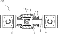
図1は、渦電流式ダンパの軸方向に沿った面での断面図である。図2は、図1の一部拡大図である。図1及び図2を参照して、渦電流式ダンパ1は、磁石保持部材2と、複数の第1永久磁石3と、複数の第2永久磁石4と、導電部材5と、ボールナット6と、ねじ軸7と、断熱部材12(図2参照)とを備える。
First Embodiment
FIG. 1 is a cross-sectional view of the eddy current damper in a plane along the axial direction. FIG. 2 is a partially enlarged view of FIG. Referring to FIGS. 1 and 2, the
[磁石保持部材]
磁石保持部材2は、ねじ軸7を中心軸とする円筒形状である。磁石保持部材2は、ボールナット6及びねじ軸7を収容可能である。磁石保持部材2の材質は、特に限定されない。しかしながら、磁石保持部材2の材質は、透磁率の高い鋼等が好ましい。磁石保持部材2の材質はたとえば、炭素鋼、鋳鉄等の強磁性材である。この場合、磁石保持部材2は、ヨークとしての役割を果たす。すなわち、第1永久磁石3及び第2永久磁石4からの磁束が外部に漏れにくくなり、渦電流式ダンパ1の減衰力が高まる。後述するように、磁石保持部材2は導電部材5に対して回転可能である。
Magnet holding member
The
[第1永久磁石及び第2永久磁石]
図3は、渦電流式ダンパの軸方向に垂直な面での断面図である。図4は、図3の一部拡大図である。図5は、第1永久磁石及び第2永久磁石を示す斜視図である。図3〜図5を参照して、複数の第1永久磁石3及び第2永久磁石4は、磁石保持部材2の外周面に取り付けられる。第1永久磁石3は、ねじ軸の周りに磁石保持部材2の円周方向に沿って配列される。同様に、第2永久磁石4は、ねじ軸の周りに磁石保持部材2の円周方向に沿って配列される。第2永久磁石4は、第1永久磁石3同士の間に配置される。つまり、磁石保持部材2の円周方向に沿って第1永久磁石3と第2永久磁石4は、交互に配置される。
[First Permanent Magnet and Second Permanent Magnet]
FIG. 3 is a cross-sectional view in a plane perpendicular to the axial direction of the eddy current damper. FIG. 4 is a partially enlarged view of FIG. FIG. 5 is a perspective view showing a first permanent magnet and a second permanent magnet. Referring to FIGS. 3 to 5, the plurality of first
第1永久磁石3及び第2永久磁石4の磁極は、磁石保持部材2の径方向に配置される。第2永久磁石4の磁極の配置は第1永久磁石3の磁極の配置と反転している。たとえば図4及び図5を参照して、磁石保持部材2の径方向において、第1永久磁石3のN極は外側に配置され、そのS極は内側に配置される。そのため、第1永久磁石3のS極が磁石保持部材2と接する。一方、磁石保持部材2の径方向において、第2永久磁石4のN極は内側に配置され、そのS極は外側に配置される。そのため、第2永久磁石4のN極が磁石保持部材2と接する。
The magnetic poles of the first
第2永久磁石4のサイズ及び特質は第1永久磁石3のサイズ及び特質と同じである。第1永久磁石3及び第2永久磁石4はたとえば、接着剤により磁石保持部材2に固定される。なお、接着剤に限らず、第1永久磁石3及び第2永久磁石4はネジ等で固定されてもよいことはもちろんである。
The size and the nature of the second
[導電部材]
図1及び図2を参照して、導電部材5は、ねじ軸7を中心軸とする円筒形状である。導電部材5は、磁石保持部材2、第1永久磁石3、第2永久磁石4、ボールナット6及びねじ軸7を収容可能である。つまり、磁石保持部材2が導電部材5の内側に同心状に配置される。導電部材5の内周面が、第1永久磁石3及び第2永久磁石4と隙間を空けて対向する。後述するように、導電部材5の表面(内周面)に渦電流を発生させるため、導電部材5は磁石保持部材2と相対的に回転する。そのため、導電部材5と第1永久磁石3及び第2永久磁石4との間には、隙間が設けられる。導電部材5に取付具8aが接続される。導電部材5と一体の取付具8aは、建物支持面又は建物内に固定される。そのため、導電部材5はねじ軸7周りに回転しない。
[Conductive member]
Referring to FIGS. 1 and 2,
導電部材5は、導電性を有する。導電部材5の材質はたとえば、炭素鋼、鋳鉄等の強磁性材である。その他に、導電部材5の材質は、フェライト系ステンレス鋼等の弱磁性材であってもよいし、アルミニウム合金、オーステナイト系ステンレス鋼、銅合金等の非磁性材であってもよい。
The
導電部材5は磁石保持部材2を回転可能に支持する。たとえば図1を参照して、磁石保持部材2の径方向において、磁石保持部材2と導電部材5との間には、ラジアル軸受9が設けられる。また、磁石保持部材2の軸方向において、磁石保持部材2と導電部材5との間には、スラスト軸受10が設けられる。なお、ラジアル軸受9やスラスト軸受10の種類は、特に限定されることなく、ボール式、ローラー式、滑り式などでもよいことはもちろんである。
The
[ボールナット]
ボールナット6は、磁石保持部材2及び導電部材5の内部に配置される。ボールナット6は、磁石保持部材2に固定される。したがって、ボールナット6が回転すれば、磁石保持部材2も回転する。ボールナット6の種類は、特に限定されない。ボールナット6は、周知のボールナットを用いてよい。ボールナット6の内周面には、ねじ部が形成されている。
[Ball nut]
The
図2を参照して、本実施形態では、ボールナット6はフランジ6aを有する。ボールナット6のフランジ6aの内側端面6bは、磁石保持部材2の1つの端面2aと対向する。ボールナット6のフランジ6aの内側端面6bと磁石保持部材2の端面2aとの間には、環状で板状の断熱部材12が設けられる。断熱部材12がボールナット6のフランジ6aの内側端面6bと磁石保持部材2の端面2aとの間に挟み込まれた状態で、ボールナット6のフランジ6aがボルト(図示省略)によって磁石保持部材2に固定される。つまり、ボールナット6と磁石保持部材2との取付部分に断熱部材12が設けられる。
Referring to FIG. 2, in the present embodiment, the
[ねじ軸]
ねじ軸7は、ボールナット6を貫通し、ボールを介してボールナット6と噛み合う。ねじ軸7の外周面には、ボールナット6のねじ部に対応するねじ部が形成されている。ねじ軸7及びボールナット6は、ボールねじを構成する。ボールねじは、ねじ軸7の軸方向の移動をボールナット6の回転運動に変換する。ねじ軸7に取付具8bが接続される。ねじ軸7と一体の取付具8bは、建物支持面又は建物内に固定される。渦電流式ダンパ1が、たとえば建物内と建物支持面との間の免震層に設置される事例の場合、ねじ軸7と一体の取付具8bが建物内に固定され、導電部材5と一体の取付具8aは建物支持面に固定される。渦電流式ダンパ1が、たとえば建物内の任意の層間に設置される事例の場合は、ねじ軸7と一体の取付具8bが任意の層間の上部梁側に固定され、導電部材5と一体の取付具8aは任意の層間の下部梁側に固定される。そのため、ねじ軸7は軸周りに回転しない。
[Screw shaft]
The
ねじ軸7と一体の取付具8b及び導電部材5と一体の取付具8aの固定は、上述の説明の逆であってもよい。すなわち、ねじ軸7と一体の取付具8bが建物支持面に固定され、導電部材5と一体の取付具8aが建物内に固定されてもよい。
Fixing of the
ねじ軸7は、磁石保持部材2及び導電部材5の内部に軸方向に沿って進退移動可能である。したがって、振動等により、渦電流式ダンパ1に運動エネルギが与えられると、ねじ軸7が軸方向に移動する。ねじ軸7が軸方向に移動すれば、ボールねじの作用によってボールナット6がねじ軸7周りに回転する。ボールナット6の回転に伴い、磁石保持部材2が回転する。これにより、磁石保持部材2と一体の第1永久磁石3及び第2永久磁石4が導電部材5に対して相対回転するため、導電部材5には渦電流が発生する。その結果、渦電流式ダンパ1に減衰力が生じ、振動を減衰させる。
The
本実施形態の渦電流式ダンパ1によれば、ボールナット6と磁石保持部材2との取付部分に設けられた断熱部材12によって、磁石保持部材2からボールナット6への熱伝導が遮断される。つまり、断熱部材12が熱伝導抑制機構として機能する。これにより、ボールナット6の温度上昇が抑制される。したがって、ボールナット6の温度上昇に起因する振動減衰性能の低下及び耐久性の低下を抑制できる。
According to the
続いて、渦電流の発生原理及び渦電流による減衰力の発生原理について説明する。 Subsequently, the generation principle of the eddy current and the generation principle of the damping force by the eddy current will be described.
[渦電流による減衰力]
図6は、渦電流式ダンパの磁気回路を示す模式図である。図6を参照して、第1永久磁石3の磁極の配置は、隣接する第2永久磁石4の磁極の配置と反転している。したがって、第1永久磁石3のN極から出た磁束は、隣接する第2永久磁石4のS極に到達する。第2永久磁石のN極から出た磁束は、隣接する第1永久磁石3のS極に到達する。これにより、第1永久磁石3、第2永久磁石4、導電部材5及び磁石保持部材2の中で、磁気回路が形成される。第1永久磁石3及び第2永久磁石4と、導電部材5との間の隙間は十分に小さいため、導電部材5は磁界の中にある。
[Attenuation force due to eddy current]
FIG. 6 is a schematic view showing a magnetic circuit of the eddy current damper. Referring to FIG. 6, the arrangement of the magnetic poles of the first
磁石保持部材2が回転すると(図6中の矢印参照)、第1永久磁石3及び第2永久磁石4は導電部材5に対して移動する。そのため、導電部材5の表面(図6では第1永久磁石3及び第2永久磁石4が対向する導電部材5の内周面)を通過する磁束が変化する。これにより導電部材5の表面(図6では導電部材5の内周面)に渦電流が発生する。渦電流が発生すると、新たな磁束(反磁界)が発生する。この新たな磁束は、磁石保持部材2(第1永久磁石3及び第2永久磁石4)と導電部材5との相対回転を妨げる。本実施形態の場合、磁石保持部材2の回転が妨げられる。磁石保持部材2の回転が妨げられれば、磁石保持部材2と一体のボールナット6の回転も妨げられる。ボールナット6の回転が妨げられれば、ねじ軸7の軸方向の移動も妨げられる。これが渦電流式ダンパ1の減衰力である。振動等による運動エネルギにより発生する渦電流は、導電部材の温度を上昇させる。すなわち、渦電流式ダンパに与えられた運動エネルギが熱エネルギに変換され、減衰力が得られる。
When the
本実施形態の渦電流式ダンパによれば、第1永久磁石の磁極の配置が、磁石保持部材の円周方向において第1永久磁石と隣接する第2永久磁石の磁極の配置と反転している。そのため、第1永久磁石及び第2永久磁石による磁界が磁石保持部材の円周方向に発生する。また、磁石保持部材の円周方向に第1永久磁石及び第2永久磁石を複数配列することにより、導電部材に到達する磁束の量が増える。これにより、導電部材に発生する渦電流が大きくなり、渦電流式ダンパの減衰力が高まる。 According to the eddy current damper of the present embodiment, the arrangement of the magnetic poles of the first permanent magnet is reversed to the arrangement of the magnetic poles of the second permanent magnet adjacent to the first permanent magnet in the circumferential direction of the magnet holding member . Therefore, a magnetic field due to the first permanent magnet and the second permanent magnet is generated in the circumferential direction of the magnet holding member. Further, by arranging a plurality of first permanent magnets and second permanent magnets in the circumferential direction of the magnet holding member, the amount of magnetic flux reaching the conductive member is increased. As a result, the eddy current generated in the conductive member is increased, and the damping force of the eddy current damper is increased.
[磁極の配置]
上述の説明では、第1永久磁石及び第2永久磁石の磁極の配置は、磁石保持部材の径方向である場合について説明した。しかしながら、第1永久磁石及び第2永久磁石の磁極の配置は、これに限定されない。
[Pole arrangement]
In the above description, the arrangement of the magnetic poles of the first permanent magnet and the second permanent magnet has been described in the case of the radial direction of the magnet holding member. However, the arrangement of the magnetic poles of the first permanent magnet and the second permanent magnet is not limited to this.
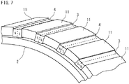
図7は、磁極の配置が円周方向である第1永久磁石及び第2永久磁石を示す斜視図である。図7を参照して、第1永久磁石3及び第2永久磁石4の磁極の配置は、磁石保持部材2の円周方向に沿う。この場合であっても、第1永久磁石3の磁極の配置は、第2永久磁石4の磁極の配置と反転している。第1永久磁石3と第2永久磁石4との間には、強磁性体のポールピース11が設けられる。
FIG. 7 is a perspective view showing a first permanent magnet and a second permanent magnet in which the arrangement of magnetic poles is in the circumferential direction. Referring to FIG. 7, the arrangement of the magnetic poles of the first
図8は、図7の渦電流式ダンパの磁気回路を示す模式図である。図8を参照して、第1永久磁石3のN極から出た磁束は、ポールピース11を通って、第1永久磁石3のS極に到達する。第2永久磁石4についても同様である。これにより、第1永久磁石3、第2永久磁石4、ポールピース11及び導電部材5の中で、磁気回路が形成される。これにより、上述と同様に、渦電流式ダンパ1に減衰力が得られる。
FIG. 8 is a schematic view showing a magnetic circuit of the eddy current damper of FIG. Referring to FIG. 8, the magnetic flux emitted from the N pole of first
[永久磁石の軸方向への配置]
渦電流式ダンパの減衰力をより大きくするには、導電部材に発生する渦電流を大きくすればよい。大きい渦電流を発生させる1つの方法は、第1永久磁石及び第2永久磁石から出る磁束の量を増やせばよい。すなわち、第1永久磁石及び第2永久磁石のサイズを大きくすればよい。しかしながら、サイズの大きい第1永久磁石及び第2永久磁石はコストが高く、磁石保持部材への取り付けも容易ではない。
[Arrangement of permanent magnet in axial direction]
In order to further increase the damping force of the eddy current damper, the eddy current generated in the conductive member may be increased. One way to generate large eddy currents is to increase the amount of magnetic flux exiting the first and second permanent magnets. That is, the sizes of the first permanent magnet and the second permanent magnet may be increased. However, the large-sized first permanent magnet and the second permanent magnet are expensive, and their attachment to the magnet holding member is not easy.
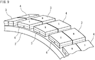
図9は、軸方向に複数個配置された第1永久磁石及び第2永久磁石を示す斜視図である。図9を参照して、第1永久磁石3及び第2永久磁石4は、1つの磁石保持部材2の軸方向に複数個配置されてもよい。これにより、1つの第1永久磁石3及び1つの第2永久磁石4それぞれのサイズは小さくて済む。一方で、磁石保持部材2に取り付けられた複数の第1永久磁石3及び第2永久磁石4の総サイズは大きい。したがって、第1永久磁石3及び第2永久磁石4のコストは安価で済む。また、第1永久磁石3及び第2永久磁石4の磁石保持部材2への取り付けも容易である。
FIG. 9 is a perspective view showing a plurality of first permanent magnets and a plurality of second permanent magnets arranged in the axial direction. Referring to FIG. 9, a plurality of first
軸方向に配置された第1永久磁石3及び第2永久磁石4の、磁石保持部材2の円周方向の配置は、上述と同様である。すなわち、磁石保持部材2の円周方向に沿って第1永久磁石3と第2永久磁石4は交互に配置される。
The circumferential arrangement of the
渦電流式ダンパ1の減衰力を高める観点から、磁石保持部材2の軸方向において、第1永久磁石3は第2永久磁石4と隣接するのが好ましい。この場合、磁気回路が磁石保持部材2の円周方向だけでなく、軸方向においても生じる。したがって、導電部材5に発生する渦電流が大きくなる。その結果、渦電流式ダンパ1の減衰力が大きくなる。
In order to increase the damping force of the
しかしながら、磁石保持部材2の軸方向において、第1永久磁石3及び第2永久磁石4の配置は特に限定されない。すなわち、磁石保持部材2の軸方向において、第1永久磁石3は第1永久磁石3の隣に配置されていてもよいし、第2永久磁石4の隣に配置されていてもよい。
However, the arrangement of the first
上述した第1実施形態では、磁石保持部材が導電部材の内側に配置されて第1永久磁石及び第2永久磁石が磁石保持部材の外周面に取り付けられ、さらに磁石保持部材が回転する場合について説明した。しかしながら、本実施形態の渦電流式ダンパは、これに限定されない。 In the first embodiment described above, the case where the magnet holding member is disposed inside the conductive member, the first permanent magnet and the second permanent magnet are attached to the outer peripheral surface of the magnet holding member, and the magnet holding member rotates further did. However, the eddy current damper of the present embodiment is not limited to this.
[第2実施形態]
第2実施形態の渦電流式ダンパは、磁石保持部材が導電部材の外側に配置され、回転しない。渦電流は、内側の導電部材が回転することで発生する。
Second Embodiment
In the eddy current damper of the second embodiment, the magnet holding member is disposed outside the conductive member and does not rotate. Eddy current is generated by rotation of the inner conductive member.
図10は、第2実施形態の渦電流式ダンパの軸方向に沿った面での断面図である。図11は、第2実施形態の渦電流式ダンパの軸方向に垂直な面での断面図である。図10及び図11を参照して、磁石保持部材2は、導電部材5、ボールナット6及びねじ軸7を収容可能である。第1永久磁石3及び第2永久磁石4は、磁石保持部材2の内周面に取り付けられる。したがって、導電部材5の外周面が、第1永久磁石3及び第2永久磁石4と隙間を空けて対向する。
FIG. 10 is a cross-sectional view in a plane along the axial direction of the eddy current damper of the second embodiment. FIG. 11 is a cross-sectional view in a plane perpendicular to the axial direction of the eddy current damper of the second embodiment. Referring to FIGS. 10 and 11,
図1に示す取付具8aは磁石保持部材2に接続される。そのため、磁石保持部材2はねじ軸7周りに回転しない。一方で、ボールナット6は、導電部材5に接続される。したがって、ボールナット6が回転すれば、導電部材5は回転する。このような構成の場合でも、上述したように、磁石保持部材2と一体の第1永久磁石3及び第2永久磁石4が導電部材5に対して相対回転するため、導電部材5には渦電流が発生する。その結果、渦電流式ダンパ1に減衰力が生じ、振動を減衰させることができる。
The
図10を参照して、本実施形態では、ボールナット6のフランジ6aの内側端面6bは、導電部材5の1つの端面5aと対向する。ボールナット6のフランジ6aの内側端面6bと導電部材5の端面5aとの間に断熱部材12が設けられる。断熱部材12がボールナット6のフランジ6aの内側端面6bと導電部材5の端面5aとの間に挟み込まれた状態で、ボールナット6のフランジ6aがボルト(図示省略)によって導電部材5に固定される。つまり、ボールナット6と導電部材5との取付部分に断熱部材12が設けられる。
Referring to FIG. 10, in the present embodiment, the
本実施形態の渦電流式ダンパ1によれば、ボールナット6と導電部材5との取付部分に設けられた断熱部材12によって、導電部材5からボールナット6への熱伝導が遮断される。つまり、断熱部材12が熱伝導抑制機構として機能する。これにより、ボールナット6の温度上昇が抑制される。したがって、ボールナット6の温度上昇に起因する振動減衰性能の低下及び耐久性の低下を抑制できる。
According to the
[第3実施形態]
第3実施形態の渦電流式ダンパは、磁石保持部材が導電部材の内側に配置され、回転しない。渦電流は、外側の導電部材が回転することで発生する。
Third Embodiment
In the eddy current damper of the third embodiment, the magnet holding member is disposed inside the conductive member and does not rotate. An eddy current is generated by rotation of the outer conductive member.
図12は、第3実施形態の渦電流式ダンパの軸方向に沿った面での断面図である。図13は、図12の一部拡大図である。図12及び図13を参照して、導電部材5は、磁石保持部材2、ボールナット6及びねじ軸7を収容可能である。第1永久磁石3及び第2永久磁石4は、磁石保持部材2の外周面に取り付けられる。したがって、導電部材5の内周面が、第1永久磁石3及び第2永久磁石4と隙間を空けて対向する。
FIG. 12 is a cross-sectional view of a surface of the eddy current damper of the third embodiment along the axial direction. FIG. 13 is a partially enlarged view of FIG. Referring to FIGS. 12 and 13, the
取付具8aは磁石保持部材2に接続される。そのため、磁石保持部材2はねじ軸7周りに回転しない。一方で、ボールナット6は、導電部材5に接続される。したがって、ボールナット6が回転すれば、導電部材5は回転する。このような構成の場合でも、上述したように、磁石保持部材2と一体の第1永久磁石3及び第2永久磁石4が導電部材5に対して相対回転するため、導電部材5には渦電流が発生する。その結果、渦電流式ダンパ1に減衰力が生じ、振動を減衰させることができる。
The
図13を参照して、本実施形態では、上記の第2実施形態と同様に、ボールナット6のフランジ6aの内側端面6bと導電部材5の端面5aとの間に断熱部材12が設けられる。そのため、本実施形態の渦電流式ダンパ1によれば、上記の第2実施形態と同様に、ボールナット6の温度上昇が抑制される。したがって、ボールナット6の温度上昇に起因する振動減衰性能の低下及び耐久性の低下を抑制できる。
Referring to FIG. 13, in the present embodiment, the
[第4実施形態]
第4実施形態の渦電流式ダンパは、導電部材が磁石保持部材の内側に配置され、回転しない。渦電流は、外側の磁石保持部材が回転することで発生する。
Fourth Embodiment
In the eddy current damper of the fourth embodiment, the conductive member is disposed inside the magnet holding member and does not rotate. Eddy current is generated by rotation of the outer magnet holding member.
図14は、第4実施形態の渦電流式ダンパの軸方向に沿った面での断面図である。図14を参照して、磁石保持部材2は、導電部材5、ボールナット6及びねじ軸7を収容可能である。第1永久磁石3及び第2永久磁石4は、磁石保持部材2の内周面に取り付けられる。したがって、導電部材5の外周面が、第1永久磁石3及び第2永久磁石4と隙間を空けて対向する。
FIG. 14 is a cross-sectional view of a surface of the eddy current damper of the fourth embodiment along the axial direction. Referring to FIG. 14,
図1に示す取付具8aは導電部材5に接続される。そのため、導電部材5はねじ軸7周りに回転しない。一方で、ボールナット6は、磁石保持部材2に固定される。したがって、ボールナット6が回転すれば、磁石保持部材2は回転する。このような構成の場合でも、上述したように、磁石保持部材2と一体の第1永久磁石3及び第2永久磁石4が導電部材5に対して相対回転するため、導電部材5には渦電流が発生する。その結果、渦電流式ダンパ1に減衰力が生じ、振動を減衰させることができる。
The
図14を参照して、本実施形態では、上記の第1実施形態と同様に、ボールナット6のフランジ6aの内側端面6bと磁石保持部材2の端面2aとの間に断熱部材12が設けられる。そのため、本実施形態の渦電流式ダンパ1によれば、上記の第1実施形態と同様に、ボールナット6の温度上昇が抑制される。したがって、ボールナット6の温度上昇に起因する振動減衰性能の低下及び耐久性の低下を抑制できる。
Referring to FIG. 14, in the present embodiment, the
上述したように、渦電流式ダンパが減衰力を発生すると、導電部材の温度は上昇する。第1永久磁石及び第2永久磁石は、導電部材と対向する。したがって、第1永久磁石及び第2永久磁石は、導電部材からの輻射熱によって温度が上昇するかもしれない。永久磁石の温度が上昇すれば、磁力が低下するおそれがある。 As described above, when the eddy current damper generates a damping force, the temperature of the conductive member rises. The first permanent magnet and the second permanent magnet face the conductive member. Therefore, the temperatures of the first permanent magnet and the second permanent magnet may increase due to radiant heat from the conductive member. If the temperature of the permanent magnet is increased, the magnetic force may be reduced.
第1実施形態の渦電流式ダンパでは、導電部材5が磁石保持部材2の外側に配置される。つまり、導電部材5が最も外側に配置されて外気と接する。これにより、導電部材5は外気によって冷却される。そのため、導電部材5の温度上昇を抑制できる。その結果、第1永久磁石及び第2永久磁石の温度上昇を抑制できる。
In the eddy current damper of the first embodiment, the
第2実施形態の渦電流式ダンパでは、磁石保持部材2が導電部材5の外側に配置される。つまり、磁石保持部材2が最も外側に配置されて外気と接する。これにより、磁石保持部材2は外気によって冷却される。そのため、磁石保持部材2を通じて第1永久磁石及び第2永久磁石を冷却できる。その結果、第1永久磁石及び第2永久磁石の温度上昇を抑制できる。
In the eddy current damper of the second embodiment, the
第3実施形態の渦電流式ダンパでは、導電部材5が磁石保持部材2の外側に配置される。つまり、導電部材5が最も外側に配置されて外気と接する。また、導電部材5は、ねじ軸7周りに回転する。これにより、回転する導電部材5は外気によって効率良く冷却される。そのため、導電部材5の温度上昇を抑制できる。その結果、第1永久磁石及び第2永久磁石の温度上昇を抑制できる。
In the eddy current damper of the third embodiment, the
第4実施形態の渦電流式ダンパでは、磁石保持部材2が導電部材5の外側に配置される。つまり、磁石保持部材2が最も外側に配置されて外気と接する。また、磁石保持部材2は、ねじ軸7周りに回転する。これにより、回転する磁石保持部材2は外気によって効率良く冷却される。そのため、磁石保持部材2を通じて第1永久磁石及び第2永久磁石を冷却できる。その結果、第1永久磁石3及び第2永久磁石4の温度上昇を抑制できる。
In the eddy current damper of the fourth embodiment, the
[第5実施形態]
第5実施形態の渦電流式ダンパは、上記した第1実施形態の渦電流式ダンパを変形したものである。
Fifth Embodiment
The eddy current damper of the fifth embodiment is a modification of the eddy current damper of the first embodiment described above.
図15は、第5実施形態の渦電流式ダンパの軸方向に沿った面での断面図である。図15を参照して、本実施形態では、ボールナット6のフランジ6aの内側端面6bと対向する磁石保持部材2の端面2aに、凹部13が形成される。凹部13は、ねじ軸7を中心とする円周方向に沿った溝である。一方、ボールナット6のフランジ6aの内側端面6bは凹部のない平坦面である。ボールナット6のフランジ6aの内側端面6bが磁石保持部材2の端面2aに接触した状態で、ボールナット6のフランジ6aがボルト(図示省略)によって磁石保持部材2に固定される。つまり、ボールナット6と磁石保持部材2との取付部分に凹部13が形成される。
FIG. 15 is a cross-sectional view of a surface of the eddy current damper of the fifth embodiment along the axial direction. Referring to FIG. 15, in the present embodiment, a recessed
本実施形態の渦電流式ダンパ1によれば、ボールナット6と磁石保持部材2との取付部分に形成された凹部13によって、磁石保持部材2とボールナット6との接触面積が小さい。そのため、磁石保持部材2からボールナット6への熱伝導が抑制される。つまり、凹部13が熱伝導抑制機構として機能する。これにより、ボールナット6の温度上昇が抑制される。したがって、ボールナット6の温度上昇に起因する振動減衰性能の低下及び耐久性の低下を抑制できる。
According to the
[第6実施形態]
第6実施形態の渦電流式ダンパは、上記した第2実施形態の渦電流式ダンパを変形したものである。
Sixth Embodiment
The eddy current damper of the sixth embodiment is a modification of the above-described eddy current damper of the second embodiment.
図16は、第6実施形態の渦電流式ダンパの軸方向に沿った面での断面図である。図16を参照して、本実施形態では、ボールナット6のフランジ6aの内側端面6bと対向する導電部材5の端面5aに、凹部13が形成される。凹部13は、ねじ軸7を中心とする円周方向に沿った溝である。一方、ボールナット6のフランジ6aの内側端面6bは凹部のない平坦面である。ボールナット6のフランジ6aの内側端面6bが導電部材5の端面5aに接触した状態で、ボールナット6のフランジ6aがボルト(図示省略)によって導電部材5に固定される。つまり、ボールナット6と導電部材5との取付部分に凹部13が形成される。
FIG. 16 is a cross-sectional view of a surface of the eddy current damper of the sixth embodiment along the axial direction. Referring to FIG. 16, in the present embodiment, a
本実施形態の渦電流式ダンパ1によれば、ボールナット6と導電部材5との取付部分に形成された凹部13によって、導電部材5とボールナット6との接触面積が小さい。そのため、導電部材5からボールナット6への熱伝導が抑制される。つまり、凹部13が熱伝導抑制機構として機能する。これにより、ボールナット6の温度上昇が抑制される。したがって、ボールナット6の温度上昇に起因する振動減衰性能の低下及び耐久性の低下を抑制できる。
According to the
[第7実施形態]
第7実施形態の渦電流式ダンパは、上記した第3実施形態の渦電流式ダンパを変形したものである。
Seventh Embodiment
The eddy current damper of the seventh embodiment is a modification of the above-described eddy current damper of the third embodiment.
図17は、第7実施形態の渦電流式ダンパの軸方向に沿った面での断面図である。図17を参照して、本実施形態では、上記の第6実施形態と同様に、ボールナット6のフランジ6aの内側端面6bと対向する導電部材5の端面5aに、凹部13が形成される。そのため、本実施形態の渦電流式ダンパ1によれば、上記の第6実施形態と同様に、ボールナット6の温度上昇が抑制される。したがって、ボールナット6の温度上昇に起因する振動減衰性能の低下及び耐久性の低下を抑制できる。
FIG. 17 is a cross-sectional view of a surface of the eddy current damper of the seventh embodiment taken along the axial direction. Referring to FIG. 17, in the present embodiment, as in the sixth embodiment described above, the
[第8実施形態]
第8実施形態の渦電流式ダンパは、上記した第4実施形態の渦電流式ダンパを変形したものである。
Eighth Embodiment
The eddy current damper of the eighth embodiment is a modification of the above-described eddy current damper of the fourth embodiment.
図18は、第8実施形態の渦電流式ダンパの軸方向に沿った面での断面図である。図18を参照して、本実施形態では、上記の第5実施形態と同様に、ボールナット6のフランジ6aの内側端面6bと対向する磁石保持部材2の端面2aに、凹部13が形成される。そのため、本実施形態の渦電流式ダンパ1によれば、上記の第5実施形態と同様に、ボールナット6の温度上昇が抑制される。したがって、ボールナット6の温度上昇に起因する振動減衰性能の低下及び耐久性の低下を抑制できる。
FIG. 18 is a cross-sectional view of a surface of the eddy current damper of the eighth embodiment taken along the axial direction. Referring to FIG. 18, in the present embodiment, the
[第9実施形態]
第9実施形態の渦電流式ダンパは、上記した第5実施形態の渦電流式ダンパを変形したものである。
[Ninth embodiment]
The eddy current damper of the ninth embodiment is a modification of the above-described eddy current damper of the fifth embodiment.
図19は、第9実施形態の渦電流式ダンパの軸方向に沿った面での断面図である。図19を参照して、本実施形態では、磁石保持部材2の端面2aと対向するボールナット6のフランジ6aの内側端面6bに、凹部14が形成される。凹部14は、ねじ軸7を中心とする円周方向に沿った溝である。一方、磁石保持部材2の端面2aは凹部のない平坦面である。ただし、磁石保持部材2の端面2aに凹部13が形成されてもよい。ボールナット6のフランジ6aの内側端面6bが磁石保持部材2の端面2aに接触した状態で、ボールナット6のフランジ6aがボルト(図示省略)によって磁石保持部材2に固定される。つまり、ボールナット6と磁石保持部材2との取付部分に凹部14が形成される。
FIG. 19 is a cross-sectional view of a surface of the eddy current damper of the ninth embodiment taken along the axial direction. Referring to FIG. 19, in the present embodiment, a
本実施形態の渦電流式ダンパ1によれば、上記した第5実施形態と同様に、ボールナット6と磁石保持部材2との取付部分に形成された凹部14によって、磁石保持部材2とボールナット6との接触面積が小さい。そのため、磁石保持部材2からボールナット6への熱伝導が抑制される。つまり、凹部14が熱伝導抑制機構として機能する。これにより、ボールナット6の温度上昇が抑制される。したがって、ボールナット6の温度上昇に起因する振動減衰性能の低下及び耐久性の低下を抑制できる。
According to the
上記した第6〜第8実施形態の渦電流式ダンパに、第9実施形態の凹部14を適用することもできる。上記した第6及び第7実施形態の渦電流式ダンパに凹部14を適用する場合、導電部材5の端面5aは凹部のない平坦面である。ただし、導電部材5の端面5aに凹部13が形成されてもよい。上記した第8実施形態の渦電流式ダンパに凹部14を適用する場合、磁石保持部材2の端面2aは凹部のない平坦面である。ただし、磁石保持部材2の端面2aに凹部13が形成されてもよい。
The
凹部13及び/又は凹部14を含む第5〜第9実施形態の渦電流式ダンパに、第1〜第4実施形態の断熱部材12を適用することもできる。
The
以上、本実施形態の渦電流式ダンパについて説明した。渦電流は導電部材5を通過する磁束の変化により発生するため、第1永久磁石3及び第2永久磁石4が導電部材5に対して相対回転すればよい。また、導電部材5が第1永久磁石3及び第2永久磁石4による磁界の中に存在する限り、導電部材と磁石保持部材との位置関係は特に限定されない。
The eddy current damper of the present embodiment has been described above. Since the eddy current is generated by the change of the magnetic flux passing through the
その他、本発明は上記の実施形態に限定されず、本発明の趣旨を逸脱しない範囲で、種々の変更が可能であることは言うまでもない。 In addition, it goes without saying that the present invention is not limited to the above embodiment, and various modifications can be made without departing from the scope of the present invention.
本発明の渦電流式ダンパは、建造物の制震装置および免震装置に有用である。 INDUSTRIAL APPLICABILITY The eddy current damper of the present invention is useful as a seismic control device and seismic isolation device for a building.
1:渦電流式ダンパ
2:磁石保持部材
3:第1永久磁石
4:第2永久磁石
5:導電部材
6:ボールナット
7:ねじ軸
8a、8b:取付具
9:ラジアル軸受
10:スラスト軸受
11:ポールピース
12:断熱部材
13、14:凹部
1: Eddy current type damper 2: Magnet holding member 3: First permanent magnet 4: Second permanent magnet 5: Conductive member 6: Ball nut 7:
Claims (3)
前記ねじ軸の周りに円周方向に沿って配列された複数の第1永久磁石と、
前記第1永久磁石同士の間に配置され、前記第1永久磁石と磁極の配置が反転した複数の第2永久磁石と、
前記第1永久磁石及び前記第2永久磁石を保持する円筒形状の磁石保持部材と、
導電性を有し、前記第1永久磁石及び前記第2永久磁石と隙間を空けて対向する円筒形状の導電部材と、
前記磁石保持部材又は前記導電部材に固定され、前記ねじ軸と噛み合うボールナットと、
前記ボールナットが前記磁石保持部材に固定される場合、前記ボールナットと前記磁石保持部材との取付部分に設けられ、前記ボールナットが前記導電部材に固定される場合、前記ボールナットと前記導電部材との取付部分に設けられる、熱伝導抑制機構と、を備える、渦電流式ダンパ。 Screw shaft,
A plurality of first permanent magnets arranged circumferentially around the screw shaft;
A plurality of second permanent magnets disposed between the first permanent magnets, wherein the arrangement of the first permanent magnet and the magnetic pole is reversed;
A cylindrical magnet holding member for holding the first permanent magnet and the second permanent magnet;
A cylindrical conductive member having conductivity and facing the first permanent magnet and the second permanent magnet with a gap in between;
A ball nut fixed to the magnet holding member or the conductive member and engaged with the screw shaft;
When the ball nut is fixed to the magnet holding member, the ball nut and the magnet holding member are provided at the attachment portion, and when the ball nut is fixed to the conductive member, the ball nut and the conductive member An eddy current damper comprising a heat conduction suppressing mechanism provided at a mounting portion of
前記ボールナットが前記磁石保持部材に固定される場合、前記熱伝導抑制機構は、前記ボールナットの取付面と前記磁石保持部材の取付面との間に設けられる断熱部材を含み、
前記ボールナットが前記導電部材に固定される場合、前記熱伝導抑制機構は、前記ボールナットの取付面と前記導電部材の取付面との間に設けられる断熱部材を含む、渦電流式ダンパ。 An eddy current damper according to claim 1, wherein
When the ball nut is fixed to the magnet holding member, the heat conduction suppressing mechanism includes a heat insulating member provided between the mounting surface of the ball nut and the mounting surface of the magnet holding member,
When the said ball nut is fixed to the said electrically conductive member, the said heat conduction suppression mechanism contains the heat insulation member provided between the attachment surface of the said ball nut, and the attached surface of the said electrically conductive member, The eddy current type damper.
前記ボールナットが前記磁石保持部材に固定される場合、前記熱伝導抑制機構は、前記ボールナットの取付面及び前記磁石保持部材の取付面のうちの少なくとも一方に形成された凹部を含み、
前記ボールナットが前記導電部材に固定される場合、前記熱伝導抑制機構は、前記ボールナットの取付面と前記導電部材の取付面のうちの少なくとも一方に形成された凹部を含む、渦電流式ダンパ。 An eddy current damper according to claim 1 or 2, wherein
When the ball nut is fixed to the magnet holding member, the heat conduction suppressing mechanism includes a recess formed on at least one of the mounting surface of the ball nut and the mounting surface of the magnet holding member.
When the ball nut is fixed to the conductive member, the heat conduction suppressing mechanism includes an eddy current damper including a recess formed in at least one of the mounting surface of the ball nut and the mounting surface of the conductive member. .
Priority Applications (1)
| Application Number | Priority Date | Filing Date | Title |
|---|---|---|---|
| JP2017205621A JP2019078331A (en) | 2017-10-24 | 2017-10-24 | Eddy current-type damper |
Applications Claiming Priority (1)
| Application Number | Priority Date | Filing Date | Title |
|---|---|---|---|
| JP2017205621A JP2019078331A (en) | 2017-10-24 | 2017-10-24 | Eddy current-type damper |
Publications (1)
| Publication Number | Publication Date |
|---|---|
| JP2019078331A true JP2019078331A (en) | 2019-05-23 |
Family
ID=66627551
Family Applications (1)
| Application Number | Title | Priority Date | Filing Date |
|---|---|---|---|
| JP2017205621A Pending JP2019078331A (en) | 2017-10-24 | 2017-10-24 | Eddy current-type damper |
Country Status (1)
| Country | Link |
|---|---|
| JP (1) | JP2019078331A (en) |
Cited By (1)
| Publication number | Priority date | Publication date | Assignee | Title |
|---|---|---|---|---|
| CN119821870A (en) * | 2025-02-28 | 2025-04-15 | 同济大学 | Self-resetting semi-underground liquid storage tank with multi-element damping units and damping method thereof |
Citations (5)
| Publication number | Priority date | Publication date | Assignee | Title |
|---|---|---|---|---|
| JPH0469046A (en) * | 1990-06-29 | 1992-03-04 | Isuzu Motors Ltd | Eddy current type reduction gear |
| JPH0629370U (en) * | 1992-09-04 | 1994-04-15 | 株式会社東芝 | Rotating electric machine with eddy current fitting |
| JPH09191634A (en) * | 1995-12-28 | 1997-07-22 | Isuzu Motors Ltd | Permanent magnet type eddy current reducer |
| JP2007211897A (en) * | 2006-02-09 | 2007-08-23 | Nsk Ltd | Ball screw and linear guide device |
| JP2017511867A (en) * | 2014-09-15 | 2017-04-27 | 政清 陳 | Outer cup rotating axial eddy current damper |
-
2017
- 2017-10-24 JP JP2017205621A patent/JP2019078331A/en active Pending
Patent Citations (5)
| Publication number | Priority date | Publication date | Assignee | Title |
|---|---|---|---|---|
| JPH0469046A (en) * | 1990-06-29 | 1992-03-04 | Isuzu Motors Ltd | Eddy current type reduction gear |
| JPH0629370U (en) * | 1992-09-04 | 1994-04-15 | 株式会社東芝 | Rotating electric machine with eddy current fitting |
| JPH09191634A (en) * | 1995-12-28 | 1997-07-22 | Isuzu Motors Ltd | Permanent magnet type eddy current reducer |
| JP2007211897A (en) * | 2006-02-09 | 2007-08-23 | Nsk Ltd | Ball screw and linear guide device |
| JP2017511867A (en) * | 2014-09-15 | 2017-04-27 | 政清 陳 | Outer cup rotating axial eddy current damper |
Cited By (1)
| Publication number | Priority date | Publication date | Assignee | Title |
|---|---|---|---|---|
| CN119821870A (en) * | 2025-02-28 | 2025-04-15 | 同济大学 | Self-resetting semi-underground liquid storage tank with multi-element damping units and damping method thereof |
Similar Documents
| Publication | Publication Date | Title |
|---|---|---|
| TWI674368B (en) | Eddy current damper | |
| JP6104678B2 (en) | Attenuator | |
| JP6863465B2 (en) | Eddy current damper | |
| WO2013151015A1 (en) | Vacuum pump | |
| JP2019100438A (en) | Eddy current damper | |
| JP7185393B2 (en) | Eddy current damper | |
| WO2019107071A1 (en) | Eddy current type damper | |
| JP2019183906A (en) | Mass damper | |
| WO2020116344A1 (en) | Eddy-current type damper | |
| JP7135725B2 (en) | Eddy current damper | |
| JP7781479B2 (en) | Damper for rotating machine and rotating machine equipped with same | |
| JP7040357B2 (en) | Eddy current damper | |
| JP7101556B2 (en) | Eddy current damper | |
| JP7040350B2 (en) | Eddy current damper | |
| JP7050619B2 (en) | Eddy current damper | |
| JP6897525B2 (en) | Eddy current damper | |
| JP6897523B2 (en) | Eddy current damper |
Legal Events
| Date | Code | Title | Description |
|---|---|---|---|
| A621 | Written request for application examination |
Free format text: JAPANESE INTERMEDIATE CODE: A621 Effective date: 20200603 |
|
| A977 | Report on retrieval |
Free format text: JAPANESE INTERMEDIATE CODE: A971007 Effective date: 20210326 |
|
| A131 | Notification of reasons for refusal |
Free format text: JAPANESE INTERMEDIATE CODE: A131 Effective date: 20210406 |
|
| A02 | Decision of refusal |
Free format text: JAPANESE INTERMEDIATE CODE: A02 Effective date: 20211012 |