JP2019081237A - Machine tool - Google Patents
Machine tool Download PDFInfo
- Publication number
- JP2019081237A JP2019081237A JP2017211261A JP2017211261A JP2019081237A JP 2019081237 A JP2019081237 A JP 2019081237A JP 2017211261 A JP2017211261 A JP 2017211261A JP 2017211261 A JP2017211261 A JP 2017211261A JP 2019081237 A JP2019081237 A JP 2019081237A
- Authority
- JP
- Japan
- Prior art keywords
- support
- spindle
- main shaft
- axis
- machine tool
- Prior art date
- Legal status (The legal status is an assumption and is not a legal conclusion. Google has not performed a legal analysis and makes no representation as to the accuracy of the status listed.)
- Granted
Links
- 230000000149 penetrating effect Effects 0.000 claims description 2
- 238000007664 blowing Methods 0.000 claims 1
- 238000001816 cooling Methods 0.000 abstract description 23
- 238000009423 ventilation Methods 0.000 abstract description 11
- 238000006073 displacement reaction Methods 0.000 description 2
- 239000000498 cooling water Substances 0.000 description 1
- 238000003754 machining Methods 0.000 description 1
- 238000000034 method Methods 0.000 description 1
- 238000012986 modification Methods 0.000 description 1
- 230000004048 modification Effects 0.000 description 1
- NJPPVKZQTLUDBO-UHFFFAOYSA-N novaluron Chemical compound C1=C(Cl)C(OC(F)(F)C(OC(F)(F)F)F)=CC=C1NC(=O)NC(=O)C1=C(F)C=CC=C1F NJPPVKZQTLUDBO-UHFFFAOYSA-N 0.000 description 1
- 230000002093 peripheral effect Effects 0.000 description 1
Images

Classifications
-
- B—PERFORMING OPERATIONS; TRANSPORTING
- B23—MACHINE TOOLS; METAL-WORKING NOT OTHERWISE PROVIDED FOR
- B23Q—DETAILS, COMPONENTS, OR ACCESSORIES FOR MACHINE TOOLS, e.g. ARRANGEMENTS FOR COPYING OR CONTROLLING; MACHINE TOOLS IN GENERAL CHARACTERISED BY THE CONSTRUCTION OF PARTICULAR DETAILS OR COMPONENTS; COMBINATIONS OR ASSOCIATIONS OF METAL-WORKING MACHINES, NOT DIRECTED TO A PARTICULAR RESULT
- B23Q11/00—Accessories fitted to machine tools for keeping tools or parts of the machine in good working condition or for cooling work; Safety devices specially combined with or arranged in, or specially adapted for use in connection with, machine tools
- B23Q11/12—Arrangements for cooling or lubricating parts of the machine
- B23Q11/126—Arrangements for cooling or lubricating parts of the machine for cooling only
- B23Q11/127—Arrangements for cooling or lubricating parts of the machine for cooling only for cooling motors or spindles
-
- B—PERFORMING OPERATIONS; TRANSPORTING
- B23—MACHINE TOOLS; METAL-WORKING NOT OTHERWISE PROVIDED FOR
- B23Q—DETAILS, COMPONENTS, OR ACCESSORIES FOR MACHINE TOOLS, e.g. ARRANGEMENTS FOR COPYING OR CONTROLLING; MACHINE TOOLS IN GENERAL CHARACTERISED BY THE CONSTRUCTION OF PARTICULAR DETAILS OR COMPONENTS; COMBINATIONS OR ASSOCIATIONS OF METAL-WORKING MACHINES, NOT DIRECTED TO A PARTICULAR RESULT
- B23Q1/00—Members which are comprised in the general build-up of a form of machine, particularly relatively large fixed members
- B23Q1/01—Frames, beds, pillars or like members; Arrangement of ways
-
- B—PERFORMING OPERATIONS; TRANSPORTING
- B23—MACHINE TOOLS; METAL-WORKING NOT OTHERWISE PROVIDED FOR
- B23Q—DETAILS, COMPONENTS, OR ACCESSORIES FOR MACHINE TOOLS, e.g. ARRANGEMENTS FOR COPYING OR CONTROLLING; MACHINE TOOLS IN GENERAL CHARACTERISED BY THE CONSTRUCTION OF PARTICULAR DETAILS OR COMPONENTS; COMBINATIONS OR ASSOCIATIONS OF METAL-WORKING MACHINES, NOT DIRECTED TO A PARTICULAR RESULT
- B23Q1/00—Members which are comprised in the general build-up of a form of machine, particularly relatively large fixed members
- B23Q1/01—Frames, beds, pillars or like members; Arrangement of ways
- B23Q1/015—Frames, beds, pillars
-
- B—PERFORMING OPERATIONS; TRANSPORTING
- B23—MACHINE TOOLS; METAL-WORKING NOT OTHERWISE PROVIDED FOR
- B23Q—DETAILS, COMPONENTS, OR ACCESSORIES FOR MACHINE TOOLS, e.g. ARRANGEMENTS FOR COPYING OR CONTROLLING; MACHINE TOOLS IN GENERAL CHARACTERISED BY THE CONSTRUCTION OF PARTICULAR DETAILS OR COMPONENTS; COMBINATIONS OR ASSOCIATIONS OF METAL-WORKING MACHINES, NOT DIRECTED TO A PARTICULAR RESULT
- B23Q1/00—Members which are comprised in the general build-up of a form of machine, particularly relatively large fixed members
- B23Q1/25—Movable or adjustable work or tool supports
- B23Q1/44—Movable or adjustable work or tool supports using particular mechanisms
- B23Q1/56—Movable or adjustable work or tool supports using particular mechanisms with sliding pairs only, the sliding pairs being the first two elements of the mechanism
-
- B—PERFORMING OPERATIONS; TRANSPORTING
- B23—MACHINE TOOLS; METAL-WORKING NOT OTHERWISE PROVIDED FOR
- B23Q—DETAILS, COMPONENTS, OR ACCESSORIES FOR MACHINE TOOLS, e.g. ARRANGEMENTS FOR COPYING OR CONTROLLING; MACHINE TOOLS IN GENERAL CHARACTERISED BY THE CONSTRUCTION OF PARTICULAR DETAILS OR COMPONENTS; COMBINATIONS OR ASSOCIATIONS OF METAL-WORKING MACHINES, NOT DIRECTED TO A PARTICULAR RESULT
- B23Q1/00—Members which are comprised in the general build-up of a form of machine, particularly relatively large fixed members
- B23Q1/25—Movable or adjustable work or tool supports
- B23Q1/44—Movable or adjustable work or tool supports using particular mechanisms
- B23Q1/56—Movable or adjustable work or tool supports using particular mechanisms with sliding pairs only, the sliding pairs being the first two elements of the mechanism
- B23Q1/58—Movable or adjustable work or tool supports using particular mechanisms with sliding pairs only, the sliding pairs being the first two elements of the mechanism a single sliding pair
-
- B—PERFORMING OPERATIONS; TRANSPORTING
- B23—MACHINE TOOLS; METAL-WORKING NOT OTHERWISE PROVIDED FOR
- B23Q—DETAILS, COMPONENTS, OR ACCESSORIES FOR MACHINE TOOLS, e.g. ARRANGEMENTS FOR COPYING OR CONTROLLING; MACHINE TOOLS IN GENERAL CHARACTERISED BY THE CONSTRUCTION OF PARTICULAR DETAILS OR COMPONENTS; COMBINATIONS OR ASSOCIATIONS OF METAL-WORKING MACHINES, NOT DIRECTED TO A PARTICULAR RESULT
- B23Q11/00—Accessories fitted to machine tools for keeping tools or parts of the machine in good working condition or for cooling work; Safety devices specially combined with or arranged in, or specially adapted for use in connection with, machine tools
- B23Q11/12—Arrangements for cooling or lubricating parts of the machine
-
- B—PERFORMING OPERATIONS; TRANSPORTING
- B23—MACHINE TOOLS; METAL-WORKING NOT OTHERWISE PROVIDED FOR
- B23Q—DETAILS, COMPONENTS, OR ACCESSORIES FOR MACHINE TOOLS, e.g. ARRANGEMENTS FOR COPYING OR CONTROLLING; MACHINE TOOLS IN GENERAL CHARACTERISED BY THE CONSTRUCTION OF PARTICULAR DETAILS OR COMPONENTS; COMBINATIONS OR ASSOCIATIONS OF METAL-WORKING MACHINES, NOT DIRECTED TO A PARTICULAR RESULT
- B23Q11/00—Accessories fitted to machine tools for keeping tools or parts of the machine in good working condition or for cooling work; Safety devices specially combined with or arranged in, or specially adapted for use in connection with, machine tools
- B23Q11/14—Methods or arrangements for maintaining a constant temperature in parts of machine tools
-
- B—PERFORMING OPERATIONS; TRANSPORTING
- B23—MACHINE TOOLS; METAL-WORKING NOT OTHERWISE PROVIDED FOR
- B23Q—DETAILS, COMPONENTS, OR ACCESSORIES FOR MACHINE TOOLS, e.g. ARRANGEMENTS FOR COPYING OR CONTROLLING; MACHINE TOOLS IN GENERAL CHARACTERISED BY THE CONSTRUCTION OF PARTICULAR DETAILS OR COMPONENTS; COMBINATIONS OR ASSOCIATIONS OF METAL-WORKING MACHINES, NOT DIRECTED TO A PARTICULAR RESULT
- B23Q11/00—Accessories fitted to machine tools for keeping tools or parts of the machine in good working condition or for cooling work; Safety devices specially combined with or arranged in, or specially adapted for use in connection with, machine tools
- B23Q11/14—Methods or arrangements for maintaining a constant temperature in parts of machine tools
- B23Q11/145—Methods or arrangements for maintaining a constant temperature in parts of machine tools using a jet of gas or cutting liquid
-
- Y—GENERAL TAGGING OF NEW TECHNOLOGICAL DEVELOPMENTS; GENERAL TAGGING OF CROSS-SECTIONAL TECHNOLOGIES SPANNING OVER SEVERAL SECTIONS OF THE IPC; TECHNICAL SUBJECTS COVERED BY FORMER USPC CROSS-REFERENCE ART COLLECTIONS [XRACs] AND DIGESTS
- Y10—TECHNICAL SUBJECTS COVERED BY FORMER USPC
- Y10T—TECHNICAL SUBJECTS COVERED BY FORMER US CLASSIFICATION
- Y10T409/00—Gear cutting, milling, or planing
- Y10T409/30—Milling
- Y10T409/303976—Milling with means to control temperature or lubricate
-
- Y—GENERAL TAGGING OF NEW TECHNOLOGICAL DEVELOPMENTS; GENERAL TAGGING OF CROSS-SECTIONAL TECHNOLOGIES SPANNING OVER SEVERAL SECTIONS OF THE IPC; TECHNICAL SUBJECTS COVERED BY FORMER USPC CROSS-REFERENCE ART COLLECTIONS [XRACs] AND DIGESTS
- Y10—TECHNICAL SUBJECTS COVERED BY FORMER USPC
- Y10T—TECHNICAL SUBJECTS COVERED BY FORMER US CLASSIFICATION
- Y10T409/00—Gear cutting, milling, or planing
- Y10T409/30—Milling
- Y10T409/309352—Cutter spindle or spindle support
Landscapes
- Engineering & Computer Science (AREA)
- Mechanical Engineering (AREA)
- Auxiliary Devices For Machine Tools (AREA)
- Machine Tool Units (AREA)
- Finish Polishing, Edge Sharpening, And Grinding By Specific Grinding Devices (AREA)
Abstract
Description
本発明は、例えば旋盤等の工作機械に関する。 The present invention relates to a machine tool such as, for example, a lathe.
従来、旋盤等の工作機械として、主軸に保持されたワークに対して複数種類の加工を行い得るようにするために、主軸を軸方向(Z軸方向)だけでなく上下方向(Y軸方向)にも移動可能とした構成のものが知られている。 Conventionally, as a machine tool such as a lathe, in order to be able to perform a plurality of types of machining on a work held on a spindle, the spindle is not only axially (z-axis direction) but also vertically (Y-axis direction) It is also known to be movable.
例えば特許文献1には、支持体の側面に軸線を水平方向に向けた姿勢で片持ち支持された主軸を支持体の側面に沿って上下方向に移動可能な構成として、主軸に保持されたワークの軸線を含む面以外の面にも各種の加工を行うことができるようにした工作機械が記載されている。 For example, in Patent Document 1, a work held by a main shaft is configured such that a main shaft supported in a cantilever manner in a posture in which the axis is directed horizontally on the side of the support can be vertically moved along the side of the support. A machine tool is described in which various processes can be performed on surfaces other than the surface including the axis line of.
一方、工作機械には、主軸等を冷却する構造ないし装置が設けられるのが一般的である。 On the other hand, a machine tool is generally provided with a structure or device for cooling a spindle or the like.
例えば特許文献2には、支持体の上面に主軸を固定状態で支持した構成において、支持体に、側面と上面との間で支持体を貫通するとともに主軸に向けて開口する通風孔を設け、当該通風孔を通して主軸の下方側から上方側に向けて風を送って主軸を冷却するようにした冷却構造を備える工作機械が記載されている。 For example, in Patent Document 2, in the configuration in which the main shaft is fixedly supported on the upper surface of the support, the support is provided with vent holes penetrating the support between the side surface and the upper surface and opening toward the main shaft. A machine tool having a cooling structure for cooling the main shaft by sending a wind from the lower side to the upper side of the main axis through the air vent is described.
主軸を軸方向だけでなく上下方向にも移動可能とした従来の工作機械では、主軸の周辺に主軸を上下方向に移動させるための移動機構が設けられることになるので、主軸を冷却するための構造ないし装置を設置するためのスペースを確保するのが困難である。そのため、主軸を冷却するための構造ないし装置を設けようとすると工作機械が大型化してしまうという問題があった。 In a conventional machine tool in which the main shaft can be moved not only in the axial direction but also in the vertical direction, a moving mechanism for moving the main shaft in the vertical direction is provided around the main shaft. It is difficult to secure a space for installing a structure or a device. Therefore, there is a problem that the machine tool becomes larger if it is attempted to provide a structure or device for cooling the spindle.
本発明は、上記課題を鑑みて成されたものであり、その目的は、工作機械を大型化させることなく主軸を冷却可能な冷却構造を有する工作機械を提供することにある。 The present invention has been made in view of the above problems, and an object thereof is to provide a machine tool having a cooling structure capable of cooling a main shaft without increasing the size of the machine tool.
本発明の工作機械は、支持体の支持面に該支持面に軸線が沿う姿勢で支持された主軸が、前記支持面に沿うとともに該主軸の軸線に直交する上下方向に移動可能である工作機械であって、前記支持体に、前記支持面と該支持面とは反対側を向く面との間で前記支持体を貫通し、前記主軸に向けて開口する通風孔が設けられていることを特徴とする。 A machine tool according to the present invention is a machine tool in which a main shaft supported on a support surface of a support in a posture in which an axis follows the support surface is movable vertically along the support surface and perpendicular to the axis of the main shaft. The support is provided with a vent hole passing through the support between the support surface and the surface facing away from the support surface and opening toward the main shaft It features.
本発明の工作機械は、上記構成において、前記主軸を前記支持面に対して上下方向に移動可能とする移動機構が、前記支持体の前記支持面の側に設けられているのが好ましい。 In the machine tool according to the present invention, in the above-described configuration, preferably, a moving mechanism that enables the main shaft to move in the vertical direction with respect to the support surface is provided on the support surface side of the support.
本発明の工作機械は、上記構成において、前記通風孔に強制的に風を流す送風機を備えているのが好ましい。 It is preferable that the machine tool of this invention is equipped with the air blower which makes an air flow forcedly through the said ventilating hole in the said structure.
本発明によれば、工作機械を大型化させることなく主軸を冷却可能な冷却構造を有する工作機械を提供することができる。 According to the present invention, it is possible to provide a machine tool having a cooling structure capable of cooling the main shaft without increasing the size of the machine tool.
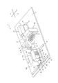
図1に示すように、本発明の一実施の形態の工作機械1は、回転するワークWを工具で切削加工(旋削加工)する旋盤として構成されている。工作機械1は、基台2の上面に、正面主軸ユニット10、ガイドブッシュ20、背面主軸ユニット30及び背面工具台40を有している。
As shown in FIG. 1, a machine tool 1 according to an embodiment of the present invention is configured as a lathe for cutting (turning) a rotating work W with a tool. The machine tool 1 has a
正面主軸ユニット10は、正面主軸台11と、正面主軸台11に回転自在に支持された正面主軸12とを有している。正面主軸12は、軸線が基台2の上面に平行(水平)となる姿勢で配置されている。
The
正面主軸12は、正面主軸台11の後端側から挿入された長尺で棒状のワークWを軸線に沿って送出可能な中空形状に形成されるとともにチャック(不図示)によりワークWを保持可能に構成されている。正面主軸台11には、例えばビルトイン型の電動モータ等の駆動源(不図示)が内蔵されており、正面主軸12は当該駆動源により駆動されてワークWを回転させることができる。
The front
基台2の上面には、正面主軸12の軸線と平行な方向に延びる一対の正面Z軸レール13が設けられている。正面主軸台11は、これらの正面Z軸レール13にスライド自在に支持されている。正面主軸台11は、例えばボールネジ機構等を備えた図示しない駆動装置により駆動されて正面Z軸レール13に沿って移動することができる。正面主軸台11を正面Z軸レール13に沿って移動させることで、正面主軸12を軸線に沿うZ軸方向に移動させることができる。
A pair of front Z-
ガイドブッシュ20は基台2に固定されたブッシュ支持台21に支持され、軸線が正面主軸12の軸線と一致するように配置されている。正面主軸12の先端から突出するワークWの先端側の部分は、ガイドブッシュ20を貫通し、ガイドブッシュ20により支持されてガイドされる。
The
工作機械1は、ガイドブッシュ20を設けない構成とすることも可能である。
The machine tool 1 can also be configured without the
背面主軸ユニット30は、背面主軸台31と、背面主軸台31に回転自在に支持された背面主軸32とを有している。背面主軸32は、軸線が正面主軸12の軸線と平行(水平)となる姿勢で正面主軸12に対向配置されている。
The
背面主軸32は、正面主軸12と軸線を一致させた状態において正面主軸12からワークWを受け取り、当該ワークWをチャック(不図示)により保持可能に構成されている。背面主軸台31には、例えばビルトイン型の電動モータ等の駆動源(不図示)が内蔵されており、背面主軸32は当該駆動源により駆動されてワークWを回転させることができる。
The back
基台2の上面には、背面主軸32の軸線に垂直で且つ水平な方向(X軸方向)に延びる一対の背面X軸レール33が設けられている。背面X軸レール33にはX軸スライドテーブル34がスライド自在に支持されている。X軸スライドテーブル34は、例えばボールネジ機構等を備えた駆動装置D1(図2参照)により駆動されて背面X軸レール33に沿って移動することができる。X軸スライドテーブル34を背面X軸レール33に沿って移動させることで、背面主軸32をX軸方向に移動させることができる。
A pair of
X軸スライドテーブル34の上面には、背面主軸32の軸線と平行なZ軸方向に延びる一対の背面Z軸レール35が設けられている。背面Z軸レール35にはZ軸スライドテーブル36がスライド自在に支持されている。Z軸スライドテーブル36は、例えばボールネジ機構等を備えた駆動装置D2(図2参照)により駆動されて背面Z軸レール35に沿って移動することができる。Z軸スライドテーブル36を背面Z軸レール35に沿って移動させることで、背面主軸32をZ軸方向に移動させることができる。
A pair of rear Z-
Z軸スライドテーブル36の上面には支持体37が固定されている。支持体37は、Z軸方向に沿って延びる壁状に構成され、X軸方向を向く一方の側面は支持面37aとなっている。支持面37aは背面主軸32の軸線に平行である。
A
支持面37aには上下方向(Y軸方向)に延びる一対の背面Y軸レール38が設けられている。背面Y軸レール38には、上記の背面主軸台31がスライド自在に支持されている。背面主軸台31が支持面37aに設けられた背面Y軸レール38に支持されることで、背面主軸32は、支持面37aに軸線が沿う姿勢となって背面主軸台31及び背面Y軸レール38を介して支持体37の支持面37aに支持されている。
A pair of rear Y-
背面主軸台31は、例えばボールネジ機構等を備えた駆動装置D3(図2、図3参照)により駆動されて背面Y軸レール38に沿って移動することができる。背面主軸台31を背面Y軸レール38に沿って移動させることで、背面主軸32を、支持面37aに沿うとともに当該背面主軸32の軸線に直交する上下方向であるY軸方向に移動させることができる。
The
以上の通り、背面主軸32は、X軸方向、Z軸方向に加えてY軸方向にも移動可能となっている。
As described above, the rear
背面主軸台31には正面工具台31cが固定され、正面工具台31cには正面加工用工具39が設置されている。正面加工用工具39は、正面主軸12の側に向けて突出しており、正面主軸12に保持されたワークWの切削加工に用いることができる。正面加工用工具39は、背面主軸32とともに、X軸方向、Y軸方向及びZ軸方向の3方向に移動可能である。
A
正面工具台31cを介して背面主軸台31に設置される正面加工用工具39は、例えば、X軸方向あるいはY軸方向に複数本並べて設けたり、Y軸方向に複数段に並べて設けたりするなど、その本数及び配置は種々変更可能である。
For example, a plurality of
背面工具台40は、正面主軸ユニット10に対してX軸方向に隣接して基台2の上面に固定されている。背面工具台40の背面主軸ユニット30の側を向く面には、複数の背面加工用工具41が設置されている。図1においては便宜上、上段の1本の背面加工用工具41と下段の1本の背面加工用工具41にのみ符号を付している。各背面加工用工具41は、それぞれ背面主軸32の側に向けて突出しており、背面主軸32に保持されたワークWの切削加工に用いることができる。これらの背面加工用工具41は、例えば背面工具台40に内蔵された駆動源により回転駆動される回転工具として構成することもできる。
The
背面工具台40に設置する背面加工用工具41は、その本数及び配置は種々変更可能である。基台2の上面に、さらに他の背面工具台を設けることもできる。
The number and arrangement of back
工作機械1は、正面主軸12を回転駆動する駆動源、背面主軸32を回転駆動する駆動源、正面主軸12をX軸方向へ移動させる駆動装置、それぞれ背面主軸32をX軸方向、Y軸方向、Z軸方向に移動させる3つの駆動装置D1〜D3、ワークWの送り装置などを統合制御して、正面主軸12の回転、背面主軸32の回転、正面主軸12の位置制御、背面主軸32の位置制御等を行うことが可能な図示しない制御部を有する。制御部により上記各装置等を統合制御することにより、ワークWに対して複数種類の切削加工を行うことができる。
The machine tool 1 includes a drive source for driving the front
例えば、背面主軸台31を移動させることで何れかの正面加工用工具39を正面主軸12に保持されたワークWと同軸に配置し、正面主軸12を所定の回転速度で回転させつつZ軸方向に移動させることで、当該ワークWの正面側を切削加工することができる。また、背面主軸台31を移動させることで背面主軸32に保持されたワークWを背面工具台40に設置された何れかの背面加工用工具41と同軸に配置し、背面主軸32を所定の回転速度で回転させつつZ軸方向に移動させることで、当該ワークWの背面側を切削加工することができる。
For example, by moving the
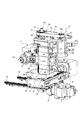
図2、図3に示すように、背面主軸台31に支持された背面主軸32を上下方向に駆動する駆動装置D3は、電動モータ50、ボールネジ機構60及びプーリー機構70を有している。
As shown in FIG. 2 and FIG. 3, the drive device D 3 for driving the rear
電動モータ50は、支持体37の上端に固定されたフレーム51に支持されて、出力軸50aを上方に向けた姿勢で、支持体37の支持面37aとは反対側となる反対面37bに間隔を空けて対向配置されている。
The
ボールネジ機構60は、背面主軸台31の上面に固定されてY軸方向と平行に起立する雄ねじ部61と、一対の軸受62により支持体37に回転自在に支持されるとともに多数のボール63を介して雄ねじ部61にねじ結合するナット部64とを有している。ナット部64は支持体37に支持されて上下方向への移動が規制されている。
The
プーリー機構70は、電動モータ50の出力軸50aに固定されて出力軸50aとともに回転する出力側プーリー71、ナット部64に固定されてナット部64とともに回転する入力側プーリー72及び出力側プーリー71と入力側プーリー72との間に掛け渡されたベルト73を有し、出力軸50aの回転をナット部64に伝達することができる。
The
電動モータ50が作動すると、出力軸50aの回転がプーリー機構70を介してナット部64に伝達され、ナット部64の回転により雄ねじ部61が上下方向に移動する。これにより、駆動装置D3によって背面主軸台31すなわち背面主軸32が上下方向に駆動される。背面主軸台31ないし背面主軸32の移動方向は電動モータ50の回転の正逆を切り替えることで変更される。
When the
本実施の形態においては、支持体37の支持面37aの側に設けられている背面Y軸レール38及びボールネジ機構60が、背面主軸32を支持体37の支持面37aに対して上下方向に移動可能とする移動機構を構成している。
In the present embodiment, the rear Y-
支持体37には、通風孔80が設けられている。通風孔80は、支持面37aと反対面37bとの間で支持体37を略水平方向に沿って貫通している。通風孔80は、支持面37aの側において一対の背面Y軸レール38の間において開口しており、当該開口は背面主軸32側に向けられている。
The
支持体37には、通風孔80に強制的に風を流すために、送風機90が装着されている。送風機90は送風ファンとして構成されており、略円筒状のシュラウド91と、シュラウド91の内部に配置されたファン92とを有している。詳細は図示しないが、ファン92は、軸心に配置された電動モータ等の駆動源により回転駆動される。送風機90は、支持体37の反対面37bに設けられたフランジ部分93にボルト等で固定されることで、通風孔80の反対面37bの側の開口に配置されている。シュラウド91の一部は通風孔80の内部に挿入されている。
A
送風機90が作動すると、支持体37の反対面37bの側から支持面37aの側に向けて通風孔80に強制的に風の流れが生じ、支持体37の反対面37bの側から通風孔80を通して背面主軸台31の内部の背面主軸32に向けて冷却風が流れ、背面主軸32を冷却することができる。
When the
背面主軸台31には背面主軸32の外周を覆う円筒状部分31aが設けられ、円筒状部分31aの外周面には複数のフィン状のヒートシンク(放熱板)31bが一体に設けられている。
The
通風孔80から背面主軸台31の内部に向けて流れる冷却風が、円筒状部分31aないしヒートシンク31bに当たることによって、当該円筒状部分31aないしヒートシンク31bを介して背面主軸台31ないし背面主軸32が冷却される。背面主軸台31ないし背面主軸32が冷却されることで、背面主軸32側の熱による不具合が防止される他、背面主軸台31ないし背面主軸32からの熱による工作機械の熱変位が抑制され、背面主軸32に保持されたワークWの加工精度の低下が防止される。
The cooling air flowing from the
背面主軸台31ないし背面主軸32のY軸方向への移動ストローク及び通風孔80の大きさは、背面主軸台31ないし背面主軸32がY軸方向の移動ストロークの範囲内において何れの位置にあっても、常に冷却風が背面主軸台31の内部に向けて流れるように設定されている。
The movement stroke of the
以上の通り、本実施の形態の工作機械1では、支持体37の支持面37aに支持された背面主軸32が支持面37aに沿って上下方向に移動可能な構成の支持体37に、支持面37aと反対面37bとの間で支持体37を貫通し、背面主軸32に向けて開口する通風孔80を設け、当該通風孔80を流れる冷却風によって背面主軸32を冷却するようにしたので、冷却水ジャケット等の冷却装置や大掛かりな冷却構造などを設けることなく背面主軸32を冷却することができる。したがって、工作機械1を大型化させることなく、背面主軸32を冷却させることが可能な小型の工作機械1を提供することができる。
As described above, in the machine tool 1 of the present embodiment, the support surface of the
本実施の形態の工作機械1では、通風孔80から背面主軸台31の内部に向けて流れる冷却風により、背面主軸台31ないし背面主軸32だけでなく、支持体37の支持面37aの側に配置された移動機構すなわち背面Y軸レール38及びボールネジ機構60をも冷却することができる。すなわち、通風孔80からの冷却風により、背面主軸32と移動機構の両方を冷却することができる。
In the machine tool 1 of the present embodiment, the cooling air flowing from the
例えば、通風口80を冷却風により背面Y軸レール38及びボールネジ機構60を直接的または間接的に冷却することができる構成としたり、背面Y軸レール38及びボールネジ機構60を通風孔80からの冷却風で冷却された支持体37や背面主軸台31を介して間接的に冷却されるように配置することなどができる。
For example, the
通風孔80からの冷却風によって背面Y軸レール38及びボールネジ機構60が冷却されることで、背面Y軸レール38ないしボールネジ機構60の熱変位が抑制され、背面主軸台31ないし背面主軸32の位置制御に誤差が生じることを防止される。したがって、背面主軸32に保持されたワークWの加工精度の低下が防止される。
The rear Y-
本発明は前記実施の形態に限定されるものではなく、その要旨を逸脱しない範囲で種々変更可能である。 The present invention is not limited to the above embodiment, and various modifications can be made without departing from the scope of the invention.
前記実施の形態においては、背面主軸32を上下方向に移動可能に支持する支持体37に通風孔80を設けて背面主軸32を冷却する場合を示しているが、正面主軸12を支持体により上下方向に移動可能な構成とし、当該支持体に通風孔を設けて正面主軸12を冷却する構成としてもよい。
In the embodiment described above, the
前記実施の形態においては、工作機械1は、正面主軸12と背面主軸32とを有する構成とされているが、1つの主軸のみを有する構成のものとしてもよい。この場合、当該1つの主軸が支持体により上下方向に移動可能に支持され、当該支持体に設けられた通風孔により主軸が冷却される構成とされる。
In the embodiment described above, the machine tool 1 is configured to have the front
前記実施の形態においては、送風機90として略円筒状のシュラウド91と、シュラウド91の内部に配置されたファン92とを有する送風ファンを用いるようにしているが、通風孔80に強制的に風を流すことができるものであれば、他の構成の送風機を用いてもよい。
In the embodiment described above, a blower fan having a substantially
前記実施の形態においては、送風機90を通風孔80の反対面37bの側の開口に配置するようにしているが、例えば通風孔80の内部に配置するなど、通風孔80に強制的に風を流すことができれば、その配置場所は種々変更可能である。
In the embodiment described above, the
前記実施の形態においては、通風孔80に反対面37bの側から支持面37aの側に向けて風を流すようにしているが、通風孔80に支持面37aの側から反対面37bの側に向けて風を流すようにしてもよい。この場合、通風孔80に生じる負圧により、背面主軸32の側から通風孔80に風が流れて背面主軸32が冷却される。
In the above embodiment, air is made to flow from the side of the
送風機90を設けることなく、背面主軸32の周りの空気が背面主軸32の熱によって加熱されて生じる対流により通風孔80に風が流れる構成としてもよい。
Instead of providing the
背面主軸32を上下方向に移動させる移動機構ないし駆動装置D3の構成、他の駆動装置D1、D2の構成等も種々変更可能である。
The configuration of the moving mechanism or the drive device D3 for moving the rear
1 工作機械
2 基台
10 正面主軸ユニット
11 正面主軸台
12 正面主軸
13 正面Z軸レール
20 ガイドブッシュ
21 ブッシュ支持台
30 背面主軸ユニット
31 背面主軸台
31a 円筒状部分
31b ヒートシンク
31c 正面工具台32 背面主軸
33 背面X軸レール
34 X軸スライドテーブル
35 背面Z軸レール
36 Z軸スライドテーブル
37 支持体
37a 支持面
37b 反対面
38 背面Y軸レール(移動機構)
39 正面加工用工具
40 背面工具台
41 背面加工用工具
50 電動モータ
50a 出力軸
51 フレーム
60 ボールネジ機構(移動機構)
61 雄ねじ部
62 軸受
63 ボール
64 ナット部
70 プーリー機構
71 出力側プーリー
72 入力側プーリー
73 ベルト
80 通風孔
90 送風機
91 シュラウド
92 ファン
93 フランジ部分
W ワーク
D1 駆動装置
D2 駆動装置
D3 駆動装置
Reference Signs List 1 machine tool 2
39
61
Claims (3)
前記支持体に、前記支持面と該支持面とは反対側を向く面との間で前記支持体を貫通し、前記主軸に向けて開口する通風孔が設けられていることを特徴とする工作機械。 A machine tool, wherein a main shaft supported on a support surface of a support in a posture in which an axis is along the support surface is vertically movable along the support surface and orthogonal to the axis of the main shaft.
A machined body characterized in that the support is provided with a vent hole penetrating the support between the support surface and a surface facing the opposite side of the support surface and opening toward the main shaft. machine.
Priority Applications (8)
| Application Number | Priority Date | Filing Date | Title |
|---|---|---|---|
| JP2017211261A JP6948915B2 (en) | 2017-10-31 | 2017-10-31 | Machine Tools |
| PCT/JP2018/037105 WO2019087667A1 (en) | 2017-10-31 | 2018-10-03 | Machine tool |
| US16/755,882 US11517990B2 (en) | 2017-10-31 | 2018-10-03 | Machine tool |
| EP18873324.0A EP3705228B1 (en) | 2017-10-31 | 2018-10-03 | Machine tool |
| CN201880065994.1A CN111201110B (en) | 2017-10-31 | 2018-10-03 | Machine tool |
| ES18873324T ES2952666T3 (en) | 2017-10-31 | 2018-10-03 | Machine tool |
| KR1020207010721A KR102656414B1 (en) | 2017-10-31 | 2018-10-03 | machine tool |
| TW107135260A TWI761606B (en) | 2017-10-31 | 2018-10-05 | work machinery |
Applications Claiming Priority (1)
| Application Number | Priority Date | Filing Date | Title |
|---|---|---|---|
| JP2017211261A JP6948915B2 (en) | 2017-10-31 | 2017-10-31 | Machine Tools |
Publications (2)
| Publication Number | Publication Date |
|---|---|
| JP2019081237A true JP2019081237A (en) | 2019-05-30 |
| JP6948915B2 JP6948915B2 (en) | 2021-10-13 |
Family
ID=66333076
Family Applications (1)
| Application Number | Title | Priority Date | Filing Date |
|---|---|---|---|
| JP2017211261A Active JP6948915B2 (en) | 2017-10-31 | 2017-10-31 | Machine Tools |
Country Status (8)
| Country | Link |
|---|---|
| US (1) | US11517990B2 (en) |
| EP (1) | EP3705228B1 (en) |
| JP (1) | JP6948915B2 (en) |
| KR (1) | KR102656414B1 (en) |
| CN (1) | CN111201110B (en) |
| ES (1) | ES2952666T3 (en) |
| TW (1) | TWI761606B (en) |
| WO (1) | WO2019087667A1 (en) |
Families Citing this family (3)
| Publication number | Priority date | Publication date | Assignee | Title |
|---|---|---|---|---|
| CN115945968B (en) * | 2023-01-09 | 2023-11-10 | 苏州群志机械设备有限公司 | Double-head vertical machining center |
| JP7681058B2 (en) * | 2023-05-10 | 2025-05-21 | 高松機械工業株式会社 | Air Cooling System |
| JP7702515B1 (en) | 2024-02-28 | 2025-07-03 | 高松機械工業株式会社 | Cooling system using environmental characteristics |
Citations (2)
| Publication number | Priority date | Publication date | Assignee | Title |
|---|---|---|---|---|
| JPH04193454A (en) * | 1990-11-26 | 1992-07-13 | Hitachi Seiko Ltd | Spindle device for belt driving type machine tool |
| JPH10512815A (en) * | 1995-02-03 | 1998-12-08 | ホンスベルク ラム ソンデルベルクツュグマシーネン ジーエムビーエイチ | Machine tool with horizontal spindle |
Family Cites Families (22)
| Publication number | Priority date | Publication date | Assignee | Title |
|---|---|---|---|---|
| CH360262A (en) * | 1958-08-20 | 1962-02-15 | Menziken Ag Maschf | Universal lathe |
| JPS52108588A (en) | 1976-03-10 | 1977-09-12 | Okuma Mach Works Ltd | Value control lathe |
| GB1578268A (en) * | 1976-06-01 | 1980-11-05 | Fujitsu Fanuc Ltd | Machine tool |
| IT1079242B (en) * | 1977-05-27 | 1985-05-08 | Innocenti Santeustacchio Spa | MILLING MACHINE |
| US4178834A (en) * | 1977-06-23 | 1979-12-18 | The Warner & Swasey Company | Machine tool having deflection compensation for tool support arm |
| JPS58201559A (en) * | 1982-05-17 | 1983-11-24 | Fanuc Ltd | Heat insulating device for spindle stock |
| JPS60178535U (en) | 1984-05-02 | 1985-11-27 | 三菱電機株式会社 | Electric discharge machining equipment |
| DE3844337A1 (en) * | 1988-12-30 | 1990-07-05 | Index Werke Kg Hahn & Tessky | MACHINE TOOL WITH COOLED MOTOR SPINDLE |
| US5027527A (en) * | 1989-08-31 | 1991-07-02 | Hughes Aircraft Company | Air-cooling system for precision measuring machines |
| US5213019A (en) * | 1991-07-17 | 1993-05-25 | Hardinge Brothers, Inc. | Headstock cooling system for a machine tool |
| JP3293242B2 (en) | 1993-05-26 | 2002-06-17 | 村田機械株式会社 | Lathe housing |
| ITMI20022077A1 (en) * | 2002-10-02 | 2004-04-03 | Parpas S P A | CONDITIONING SYSTEM FOR AN OPERATING MACHINE, IN PARTICULAR FOR A MACHINE TOOL |
| JP2008540145A (en) * | 2005-05-16 | 2008-11-20 | シュタルラークヘッケルト アーゲー | Machine tool with two clamping points on separate carriages |
| US7172375B2 (en) * | 2005-06-23 | 2007-02-06 | Mori Seiki Co., Ltd. | Machine tool |
| DE102006026184A1 (en) * | 2006-05-30 | 2007-12-06 | Index-Werke Gmbh & Co. Kg Hahn & Tessky | Turning machining center |
| JP5001870B2 (en) * | 2008-02-07 | 2012-08-15 | 三菱重工業株式会社 | Machine Tools |
| WO2011132314A1 (en) | 2010-04-23 | 2011-10-27 | 三菱重工業株式会社 | Structure for suppressing column heat deformation in machine tools |
| CN101885075B (en) * | 2010-07-01 | 2012-05-23 | 东南大学 | Air cooling device for controlling thermal deformation of spindle box of vertical machine tool |
| CN201693189U (en) * | 2010-07-01 | 2011-01-05 | 东南大学 | An air cooling device for controlling the thermal deformation of the spindle box of a vertical machine tool |
| CN201807743U (en) * | 2010-07-02 | 2011-04-27 | 东南大学 | Novel air cooling device used for controlling thermal deformation of main spindle box of vertical processing machine tool |
| CN102744428B (en) | 2012-07-12 | 2015-02-04 | 浙江日发精密机械股份有限公司 | Air cooling electric spindle device for precision numerical control lathe |
| US10259089B2 (en) * | 2017-03-17 | 2019-04-16 | Maxxtron Technology Co., Ltd | Cooling system of machine tool body casting |
-
2017
- 2017-10-31 JP JP2017211261A patent/JP6948915B2/en active Active
-
2018
- 2018-10-03 CN CN201880065994.1A patent/CN111201110B/en active Active
- 2018-10-03 ES ES18873324T patent/ES2952666T3/en active Active
- 2018-10-03 WO PCT/JP2018/037105 patent/WO2019087667A1/en not_active Ceased
- 2018-10-03 US US16/755,882 patent/US11517990B2/en active Active
- 2018-10-03 KR KR1020207010721A patent/KR102656414B1/en active Active
- 2018-10-03 EP EP18873324.0A patent/EP3705228B1/en active Active
- 2018-10-05 TW TW107135260A patent/TWI761606B/en active
Patent Citations (3)
| Publication number | Priority date | Publication date | Assignee | Title |
|---|---|---|---|---|
| JPH04193454A (en) * | 1990-11-26 | 1992-07-13 | Hitachi Seiko Ltd | Spindle device for belt driving type machine tool |
| JPH10512815A (en) * | 1995-02-03 | 1998-12-08 | ホンスベルク ラム ソンデルベルクツュグマシーネン ジーエムビーエイチ | Machine tool with horizontal spindle |
| US5944643A (en) * | 1995-02-03 | 1999-08-31 | Honsberg Lamb Sonderwerkzeugmaschinen Gmbh | Machine tool with horizontal spindles |
Also Published As
| Publication number | Publication date |
|---|---|
| US11517990B2 (en) | 2022-12-06 |
| US20210086320A1 (en) | 2021-03-25 |
| CN111201110B (en) | 2022-09-27 |
| TWI761606B (en) | 2022-04-21 |
| JP6948915B2 (en) | 2021-10-13 |
| EP3705228A4 (en) | 2021-07-28 |
| EP3705228A1 (en) | 2020-09-09 |
| KR102656414B1 (en) | 2024-04-12 |
| TW201918304A (en) | 2019-05-16 |
| KR20200070250A (en) | 2020-06-17 |
| WO2019087667A1 (en) | 2019-05-09 |
| ES2952666T3 (en) | 2023-11-03 |
| EP3705228B1 (en) | 2023-06-28 |
| CN111201110A (en) | 2020-05-26 |
Similar Documents
| Publication | Publication Date | Title |
|---|---|---|
| CN100571977C (en) | Lathe with main body covered with cover | |
| WO2019087667A1 (en) | Machine tool | |
| JP2007000966A (en) | Machine tool | |
| JP2017064867A5 (en) | ||
| JP7195305B2 (en) | Machine Tools | |
| JP2007075995A (en) | Machine tool | |
| JP2015164751A (en) | Gear processing device | |
| CN110052625B (en) | A Rotary Center That Improves Machining Accuracy | |
| CN206732563U (en) | A Highly Cooling and Cleaning Integrated Machining Center | |
| JP2009214187A (en) | Machine tool | |
| KR101970192B1 (en) | Transfer apparatus for machine tool | |
| JPH1148087A (en) | Machine tools with built-in motor headstock | |
| JPH0911157A (en) | Electric tool | |
| CN221088065U (en) | A workpiece clamping mechanism for CNC machine tools | |
| JP6572562B2 (en) | Machine Tools | |
| JPH07237085A (en) | Spindle cooling device for processing machine | |
| KR20120109312A (en) | machine tool | |
| JPH07328889A (en) | Cooling device for spindle unit in PCB processing machine | |
| CN208495780U (en) | A kind of equipment removing knuckle cast gate | |
| JP6990483B2 (en) | Jig grinding machine with upward exhaust / heat exhaust structure | |
| CN224088410U (en) | A vertical single-axis CNC drilling and milling machine | |
| CN223656495U (en) | A high-precision horizontal machining center | |
| KR20180115492A (en) | Cooling device of main spindle for machine tools | |
| JP3120334U (en) | Power tool adapter | |
| CN210849327U (en) | A reciprocating turning tool changer assembly |
Legal Events
| Date | Code | Title | Description |
|---|---|---|---|
| A621 | Written request for application examination |
Free format text: JAPANESE INTERMEDIATE CODE: A621 Effective date: 20200421 |
|
| A131 | Notification of reasons for refusal |
Free format text: JAPANESE INTERMEDIATE CODE: A131 Effective date: 20210511 |
|
| A521 | Request for written amendment filed |
Free format text: JAPANESE INTERMEDIATE CODE: A523 Effective date: 20210706 |
|
| TRDD | Decision of grant or rejection written | ||
| A01 | Written decision to grant a patent or to grant a registration (utility model) |
Free format text: JAPANESE INTERMEDIATE CODE: A01 Effective date: 20210907 |
|
| A61 | First payment of annual fees (during grant procedure) |
Free format text: JAPANESE INTERMEDIATE CODE: A61 Effective date: 20210921 |
|
| R150 | Certificate of patent or registration of utility model |
Ref document number: 6948915 Country of ref document: JP Free format text: JAPANESE INTERMEDIATE CODE: R150 |
|
| R250 | Receipt of annual fees |
Free format text: JAPANESE INTERMEDIATE CODE: R250 |